Abstract
This paper presents an experimental and numerical investigation of the tensile and compressive behaviour of a novel U-connector in the cold-formed steel (CFS) truss-to-column connection. Tensile tests were performed on 12 specimens representing the tension chords of the trusses in the connection. The results were used to validate a finite element model. The validated model was then subjected to both compressive and tensile loads, which revealed low stiffness in both the compressive and tensile components of the proposed connection. An optimisation of the geometry by using one long nut instead of two nuts was carried out to improve the behaviour and stiffness of the connection. The optimised results were compared with both experimental and numerical data, and conclusions were drawn regarding the effectiveness of the components in the proposed connection. The use of long-nut optimisation in the tension and compression components of the proposed connection shows a significant increase in load-bearing capacity, which makes it very promising for future applications in CFS truss-to-column connections. However, further validation through experimental testing is required to confirm the effectiveness and reliability of the connection in full-scale structures.
1. Introduction
The use of cold-formed steel (CFS) elements in wall panel systems has been gradually increasing in recent years both in the field of structural systems and as non-structural architectural components. This is due to their high strength-to-weight ratio, cost-effectiveness, prefabrication and fast assembling on-site, environmental protection and good seismic performance [1,2,3]. The connections between the floor structures and the wall panels remain questionable due to the high level of fabrication of the panels. This uncertainty arises from the complete closure of the panels on all sides when they arrive on site. As it is well known, connections in CFS structures are most critical for design and are largely responsible for the CFS member’s strength and assembly efficiency [4,5]. As a result, researchers are constantly working on the development of new types of joints that will enable the CFS structure to perform better. The main elements of the CFS wall panels are C-profile studs and tracks, while many floor systems consist of truss beams as floor joists [6,7,8,9,10,11]. Bondok and Salim [12] experimentally investigated a type of connection for roof trusses that can resist shear and tension loads. Additionally, they concluded that the truss-end connections are one important component that, if improperly designed, can lead to the premature failure of the structure. Obeydi et al. [13] experimentally and numerically investigated clip angles made from CFS for joining CFS members including CFS trusses. Wang et al. [14,15,16] investigated the structural performance of a light-steel-beam-column connection. The evaluation was carried out on cruciform specimens of square hollow section (SHS) columns and cold-formed tubular steel roof trusses connected with a patented U-connector for truss K-joints. Furthermore, Fan et al. [2] presented a detailed description of a new truss-to-column connection and a suitable structure system for its use. Tankova et al. [17] and da Silva et al. [18] used innovative plug-and-play solutions for connecting CFS trusses to tubular columns. The proposed solution consists of a socket welded to the column and a T-plug bolted to the bottom and top chords of the CFS trusses. It is noted that the solutions briefly presented above are not suitable for the connection of CFS truss beams with a cold-formed C-profile column in a way that will ensure both the continuity of trusses over many spans and submersion between the walls. Floor joists or roof trusses are usually constructed as freely supported beams and placed between walls. However, when they are designed as continuously supported beams, they must be placed on top of the walls, requiring a greater height of the structure. In order to achieve continuity of the trusses over more spans and at the same time keep the trusses submerged between walls, a connection with two innovative connectors for CFS members has been designed (Figure 1).
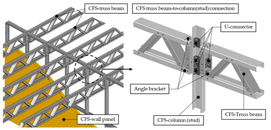
Figure 1.
Double-sided CFS-truss to column connection.
One of these connectors is a novel angle bracket that was presented in a previous study [19]. It can be used to anchor CFS members and panels and to connect truss ends to CFS columns, concrete, steel or other common structures. Due to the low local stiffness of thin-walled C-profiles, it is impossible to achieve continuity of CFS trusses over the flanges of CFS columns by using only angle brackets. Therefore, a new U-connector was developed to increase the local stiffness of the CFS C-profile (Figure 2). The shape of the U-connector is achieved through the cold-pressing of a 3 mm thick DX51D steel plate. This novel U-connector has four stiffening darts, two on each angle, for higher stiffness. The U connector is installed inside the C-profile and is fastened to it with eight M6 class 10.9 self-tapping screws, four on the web and two on each flange. To increase the bearing capacity of the screwed connection and to improve the coupling between the C-profile and the U-connector, dimples were formed on both parts. This is beneficial for coupling because the shear between parts is not only transferred with screws, but with the contact forces on the dimples themselves. The U-connector has pre-drilled holes for self-tapping screws with a diameter of 5.2 mm, while the C-profile has clearance holes with a diameter of 6 mm. The connection to trusses or other elements from CFS is accomplished using M12 bolts through 13 mm holes in the centre of the web and on both flanges. This design allows easy and uncomplicated connection of different elements on site or in the factory.
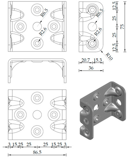
Figure 2.
Dimensions of the U-connector.
The double-sided CFS truss-to-column connection subjected to bending can be divided into three main components: the tension chord, the compression chord and the shear component as shown in Figure 3. The tension chord, positioned at the top of the truss beams, consists of two C-profiles with angle brackets at each end, a C-profile column and an inserted U-connector fastened to the column. The connection between the CFS truss and the column is secured with two M12 bolts of property class 10.9 and nuts of class 8.8. At the lower end of the truss beam, there is also a compression chord, which is symmetrical to the tension chord but identical in composition. This chord consists of the same components as the tension chord. The third component of the connection is a shear component consisting of two vertical studs of a truss beam with two inserted U-connectors, a CFS column with inserted U-connector and two M12 bolts of property class 10.9 with nuts of class 8.8 connecting these three parts.
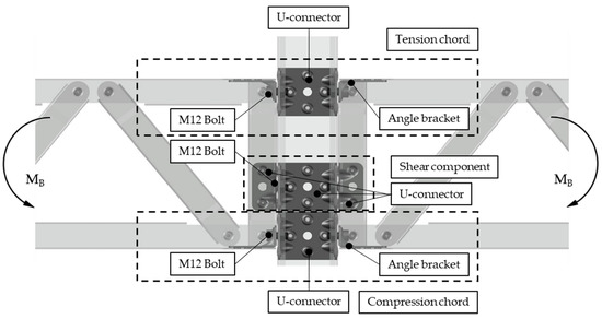
Figure 3.
Three main components of CFS—truss to column connection.
The primary goal of applying innovative connectors is to ensure the continuity of the truss beams. Therefore, it is necessary to determine their load capacity when exposed to different load conditions. In this context, an experimental investigation was conducted to understand the behaviour and to correctly assess the load transfer mechanisms of the tensile component in the proposed connection. After the experimental tests, a validation of the finite element model was carried out in ABAQUS [20]. The validated finite element model was then used to determine the capacity and behaviour of the compression component. In addition, an optimisation of the proposed connection was also carried out.
2. Experimental Study
2.1. Test Specimen
The geometry and dimensions of the test specimen are shown in Figure 4 and listed in Table 1. The test specimen is composed of two 305-millimetre-long C-profiles that have angle brackets installed on the inner ends. They are joined together by a U-connector using two M12 bolts of class 10.9 and property class 8.8 nuts, respectively. The nominal cross-sectional dimensions of C-profiles are 89 × 42 × 12 mm, where 89 mm is the width, 42 mm is the height, and 12 mm is the width of the stiffening lips. C-profiles have a nominal thickness of 1.15 mm. M12 bolts are standardized bolts according to DIN 6921 [21], while the nut dimensions are according to EN 1661 [22], respectively. The specimen’s total length, including all connected parts, is 699 mm. Eight holes each with a diameter of 13 millimetres are predrilled at the ends of the C-profile and are used to hold the specimen on the test tool. A total of 12 specimens were prepared for testing. The specimens are labelled as UT-x, where x is the specimen number, T denotes the tensile test, and U denotes the U-connector.
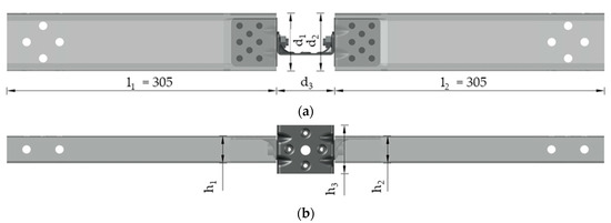
Figure 4.
Details of test specimen (mm): (a) Plan view, (b) Front view.

Table 1.
Dimensions of test specimens.
2.2. Material Properties
The C-profile is manufactured using high-strength steel S550 GD, while the U-connector and angle brackets are made of high-ductility steel DX51D Z275. The M12 bolts are of class 10.9 and the nuts used are of property class 8.8. Uniaxial tensile tests were performed at room temperature to verify the mechanical properties of the steel in accordance with method A of the EN ISO 6892-1:2019 standard for metallic materials [23]. The values of Young’s modulus E, upper yield stresses ReH and tensile strengths Rm are shown in Table 2. Elongations measured with external extensometers on a gauge length of 50 mm are also shown with values of strain at yield point Ae, percentage total extension at maximum force Agt, and at fracture At.
Table 2.
Material properties for steel S550 GD and DX51D Z275 [19].
2.3. Test Setup and Measuring Equipment
The laboratory tests were performed on the universal tension–compression test machine Zwick/Roell Z600. Test management and data registration were carried out using TestXpert II v3.61 software. The test setup is shown in Figure 5a,b. The test specimen was connected to test tools with eight M12 bolts of class 10.9 on each end of the C-profiles (Figure 5c). To ensure a rigid, non-slip joint between the test tools and the test specimen, the M12 bolts are preloaded with a maximum force of 50 kN, corresponding to a tightening torque of 120 Nm. The required tightening torque was calculated according to EN 1993-1-8 [24]. In addition, both sides of the specimen have joints to allow for free rotation. The specimens were tested using hydraulic jaws with a capacity of up to 500 kN. The tension in the specimen is applied using the displacement control of the movable crosshead at a test speed of 5.0 mm/min. During the test, the axial force and displacements in the moving crosshead were recorded. The test was finished when the load value dropped by 30%. The specimen dimensions (Figure 4) were remeasured after the test.
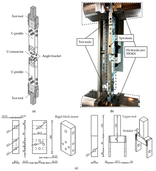
Figure 5.
(a) test specimen with test tools (b) Test setup, (c) Dimension of test tool [mm].
3. Test Results
3.1. Load-Bearing Capacity
Force-displacement curves obtained by tensile testing of twelve specimens are shown in Figure 6. Table 3 shows the values of the maximum force Fmax, displacement at maximum force x, elastic stiffness K, and the relative elongation of the U-connector after the test, Δl. The average value and standard deviation are shown at the bottom of Table 3.
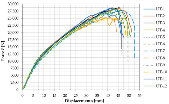
Figure 6.
Force-displacement curves for the test specimens UT-1–UT-12.
Table 3.
Results of the experimental testing.
Furthermore, after the test, the dimensions of the specimens were also measured as shown in Table 4.
Table 4.
Dimensions of the specimens after experimental testing.
The average value of the maximum load was 27,323 N with a corresponding displacement of 43.01 mm. Relative standard deviations for the maximum load value, the corresponding displacement, and the elastic stiffness are 5.16%, 6.73%, and 7.66%, respectively. The average value of elastic stiffness was found to be 1455 N/mm. This is a low value and indicates that the continuity of the tension chords in the trusses may not be achieved. Additionally, the average displacement of the U-connector alone after the test was 36.5 mm. The load value of the elastic part of the connection is estimated to be about 7500 N, which corresponds to about 27% of the average maximum force, as shown by the force-displacement curves.
3.2. Failure Mode
During the tensile test of the double-sided connection of the C-profile with the U-connector and two angle brackets, several characteristic behaviours were observed (Figure 7). Elastic bending of the U-connector and angle brackets occurs first. At an approximate load value of 7500 N and a global displacement of 5 mm, plastic deformation of the connectors begins. The bending of the web of the C-profiles occurs due to the eccentricity of the load on angle brackets and the U-connector. At an average load value of 27,323 N and a displacement of 43 mm, the M12 nut starts to pull through, but the edge of the U-connector’s flange tears at the end. The identical failure mode was observed across all specimens, as shown by the severe plastic deformation of the U-connector, with the M12 nut being pulled through the flange of the U-connector and the M12 bolt shank tearing its end.
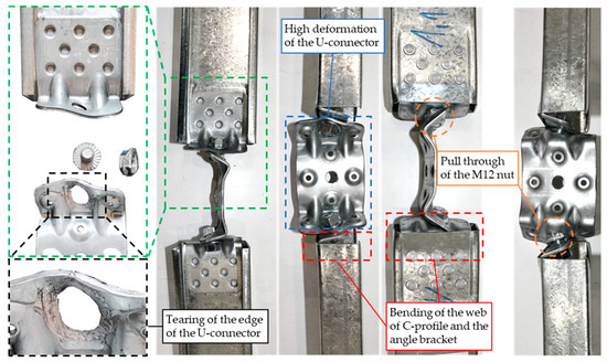
Figure 7.
Failure mode of connection.
4. Numerical Simulation
The numerical simulation of the double-sided connection of the C-profile with the U-connector and two angle brackets was performed using the FEA software ABAQUS [20]. Validation of the numerical model was carried out based on the results of laboratory tests of the connection exposed to tensile load. The validated model was used for the simulation of a double-sided connection of the C-profile with the U-connector and two angle brackets under compression loading. Furthermore, a proposal for optimizing the connection is presented.
4.1. Finite Element Model
4.1.1. Geometry
The numerical model’s geometry was equal to the geometry of the test specimen with nominal dimensions. The model consists of several components, including a C-profile, an angle bracket, a U-connector and an M12 bolt with a nut. Within the assembly module, repeating parts were duplicated to form a complete model.
4.1.2. Interactions and Boundary Conditions
The connection between the angle brackets and the C-profiles was established through eight protrusions, using a tie constraint. Previous research has indicated that there is no relative displacement between the C-profile and the angle bracket [21]. The tie constraint was also used to connect the bolt and nut. The surface-to-surface contacts between the U-connector and the angle brackets were determined with both tangential and normal interaction properties. The tangential behaviour was described using a penalty friction formulation with a friction coefficient of 0.19 according to Quan et al. [25], while hard contact was used for the normal behaviour. The same contact definitions were also used for the surfaces between the angle brackets and C-profiles. The node-to-surface discretization method was used for the contacts between the nuts and the U-connector, the bolt heads and angle brackets, the bolt shanks and the edges of the U-connector and angle brackets, as well as the U-connector and the edge of the C-profile section. The reference point was coupled to the surfaces surrounding the holes at the end of the C-profiles. The reference points were constrained; only the UR2 rotation was allowed to move freely. A load was applied as a displacement to a reference point in the direction of the specimen. The finite element model, including interactions and boundary conditions, is shown in Figure 8.
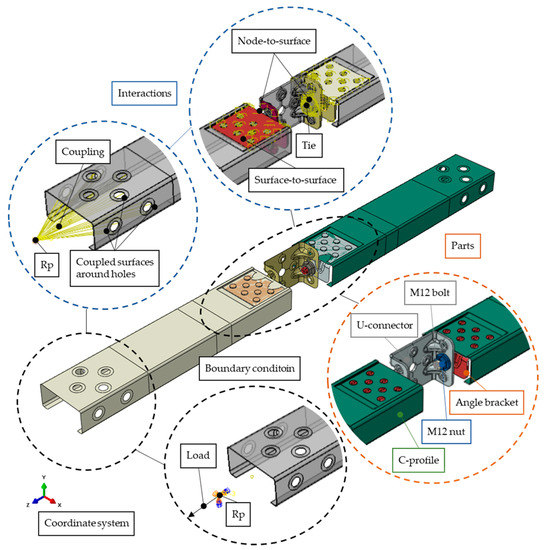
Figure 8.
FE-model with model parts, interactions and boundary conditions.
4.1.3. Material Models
In this study, an elastoplastic material model was used for all materials. The bolts and nuts are of property class 10.9 and 8.8 and were modelled with bilinear materials, using the mechanical properties as outlined in Pang et al. [26]. The plastic properties of the steel were defined in ABAQUS using true stresses and true strains . The steel S550 GD was modelled using a bilinear material model, while a multi-linear model was used for the steel DX51D. The material properties for each material are provided in Table 5.
Table 5.
Material properties for FEM.
4.1.4. Element Type and Mesh Size
The mesh distribution for the FE model and the individual parts are shown in Figure 9.
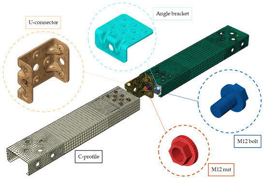
Figure 9.
Mesh distribution on FE model and parts individually.
Linear solid elements with reduced integration (C3D8R) were used to model the bolts and nuts, while quad-dominated linear shell elements (S4R) were used for the C-profiles, U-connector and angle brackets. The mesh size for the C-profile was set to 8 mm, while a finer mesh size of 2 mm was used for the more critical parts of the C-profile, especially around the holes and near the edge. A global seed size of 1.8 mm was chosen for the angle brackets, with a local seed size of 1 mm around the bolt hole with a diameter of 13 mm. The same meshing strategy was applied for the U-connector, with the global seed size set to 2 mm, with local seeds of 1 mm around the holes with a diameter of 13 mm. Since the bolts had master surfaces in contact, their mesh was coarser, with a size of 1.5 mm. The nuts, on the other hand, had slave surfaces, so their mesh was finer, with a size of 1 mm.
4.1.5. Validation of Numerical Model
ABAQUS/Standard was used for the analysis, while a static, general procedure was applied with Nlgeom enabled for high deformations. The load-displacement responses obtained from the experimental results and finite element analysis (FEA) were compared, as presented in Figure 10. An average load-displacement curve was generated for the experimental results. The FEA results were compared with the experimental results by using the average characteristic values from the average load-displacement curve. The change in the height of the C-profile was also compared, using the average value from Table 4. To validate the results of the FE model, areas under the force-displacement curves were compared, while the ratio between the average experimental and numerical values was used, as shown in Table 6.
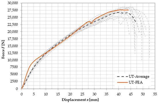
Figure 10.
Force-displacement curve comparison between the average value of experimental results and FEA.
Table 6.
Comparison of the FEA result and results of the experimental testing.
The results obtained from finite element analysis (FEA) show considerable similarity with the experimental data. Initially, the FEA model shows higher stiffness, which is due to the use of ideal test tool joints in the FE model. The onset of plastic deformation is observed at an approximate value of 7500 N, which agrees with the experimental value and can be visually seen on the force-displacement curves in Figure 10. In particular, the maximum load reached in the FEA model is only 4% of the value reached in the average force-displacement curve of the experimental tests. Furthermore, the displacement observed at maximum load in the FEA model has a lower deviation from the experimental data of 1%. To obtain the failure deformation, a definition of the damage parameters is required. For the purposes of this study, the level of accuracy achieved without damage parameters was considered satisfactory. Figure 11 and Figure 12 illustrate the results of the FEA model in terms of von Mises stresses at peak load and at the end of the simulation. The results are compared with the tested specimens, highlighting the similarity between the FEA and experimental data.
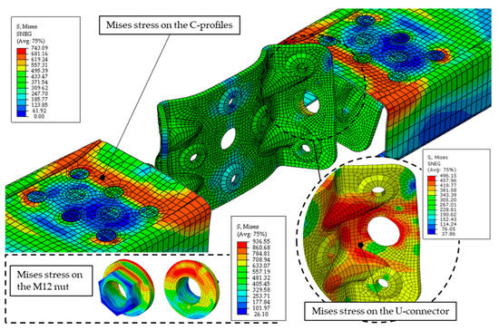
Figure 11.
von Mises stress distribution on the C-profiles and the U-connector at the ultimate load obtained by FEA.
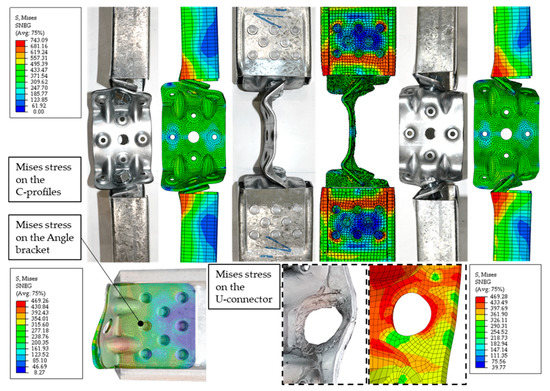
Figure 12.
von Mises stress distribution on the C-profiles, a U-connector and an angle bracket at the end of simulation obtained by FEA.
In order to highlight the stresses on the C-profile and the U-connector, the M12 bolts and nuts were not displayed in the global FE model but were shown separately together with the corresponding von Mises stress. The stress distribution shown in Figure 11 indicates that the upper and stiffer sections of the flanges transmit most of the load. Furthermore, the non-uniform stress distribution on the M12 nut indicates that pull-through failure may start, resulting in a decrease in the ultimate load. Comparing the FEA and experimental results, Figure 12 shows excellent agreement between the deformed shapes and the stress distributions. The deformation of the hole on the flange is clearly visible and is supported by the corresponding stress distribution on the U-connector.
4.2. Numerical Simulation of CFS Connection under Compression Loading
To ensure the convergence of the FE model, the free rotations of the UR2 boundary condition were constrained while the direction of a 20 mm displacement load on the Z-axis was assigned in the opposite direction. In order to introduce imperfections, an eigenvalue buckling analysis was performed in ABAQUS, using compression loading as the basis. The first and third buckling modes were considered. These modes are primarily local buckling eigenmodes, which arise due to the connection between the C-profile and the angle bracket which transfers the load through the web of the C-profile. The first and third eigenmodes were selected because they are identical, but occur on different C-profile members. They were introduced as geometric imperfections with scaling factors of 0.34 t for local buckling modes, as recommended by Schafer and Peköz [27] through experimental and analytical investigations. The amplitudes of these imperfections were selected from the 50% value of the Cumulative Distribution Function (CDF) of the experimentally measured imperfection data in accordance with the modelling suggestions of Schafer and Peköz [27]. The notation UC-FEA refers to the specimen, where U stands for the U-connector, C for the compressive load and FEA for the finite element analysis. The results of the numerical simulation for the compression-loaded specimens are shown in Table 7.
Table 7.
Result comparison of the compression component of the proposed connection.
Specimens subjected to the compressive load experienced a higher initial stiffness. However, the maximum load value achieved was considerably lower. The von Mises stress of the FE model is shown in Figure 13 for the displacements at maximum load and at the end of the simulation.
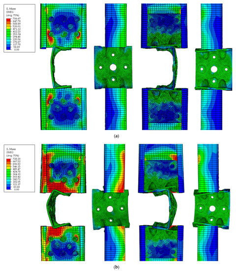
Figure 13.
von Mises stresses of the FE model of the compression component at (a) maximum load value and (b) end of simulation or 20 mm.
Plastic deformation occurred at a load value of about 4700 N with a corresponding displacement of 1.5 mm. The maximum load value of 7696 N is reached at a displacement of 8.25 mm, after which a slight decrease in load value was observed. At a displacement of 13 mm, contact between the U-connector and the edge of the C-profile’s web occurred, resulting in an increase in the load value. The subsequent increase in force due to contact between the C-profile and the U-connector is not considered the maximum load value, as it does not exclusively reflect the behaviour of the U-connector.
4.3. Optimisation of CFS Connection under Compression Loading
Based on the previously presented results, it was found that the proposed connection for truss beams has relatively low stiffness, making it suitable only for light-load applications. In order to address this issue and increase the initial elastic stiffness, an optimization of the proposed connection was carried out. Furthermore, an analysis of the angle bracket alone in the previous work showed that its elastic stiffness was about 7.7 kN/mm [19]. The optimization was designed to maximize the use of the angle brackets in the truss beams while minimizing the load-transmitting role of the U-connector and CFS column in the tension and compression components of the connection. To achieve this, two nuts were replaced with a longer nut connecting two truss beams at the tension and compression chords. This longer nut was produced from a hexagonal steel bar with a circumscribed circle diameter of 19 mm. M12 threaded blind holes 30 mm long were made on both sides of the long nut and the total length of the nut was 80.5 mm. This optimization should result in the connection behaving more like an anchored angle bracket. The optimised connection of truss beams and the CFS column is shown in Figure 14.
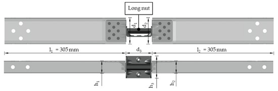
Figure 14.
Proposed tensile or compression component of the proposed connection with long nut optimisation.
Finite Element Modelling
In order to perform a numerical analysis of the optimized connection, a validated finite element model from Section 4.1 was used. The long nut was modelled with linear solid elements with reduced integration (C3D8R). The material properties of the long nut were based on the steel grade C45E, which was modelled as an elastoplastic bilinear material with a minimum yield strength of 430 MPa, tensile strength of 650 MPa and an elongation at fracture of 16% according to EN 10277-5-2008 [28]. For the material model, engineering values of strains and stresses were transformed to true values as described in Section 4.1.3. For the FE model of the compression component, the same steps as described in Section 4.2 were applied.
The nomenclature used for the results is consistent with the previous chapters, with the addition of the letter “O” to indicate optimization. Specifically, the results are labelled “UCO-FEA” and “UTO-FEA,” where “O” stands for optimized. The von Mises stresses of the UTO FE model are shown in Figure 15 for displacements at maximum load.
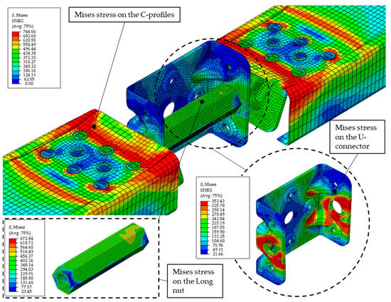
Figure 15.
von Mises stress distribution for the optimised tensile component on the C-profiles, a U-connector and the long nut at the ultimate load obtained by FEA.
The equivalent plastic strains of the angle bracket and the von Mises stress of the M12 bolt are shown in Figure 16 at the end of the simulation.
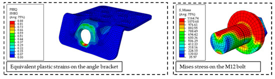
Figure 16.
Equivalent plastic strains on the angle bracket and von Mises stress on the M12 bolt for the case of the tensile component.
Finally, Figure 17 shows the von Mises stress of the entire FE model at the end of the simulation, while the results are shown in Table 8.
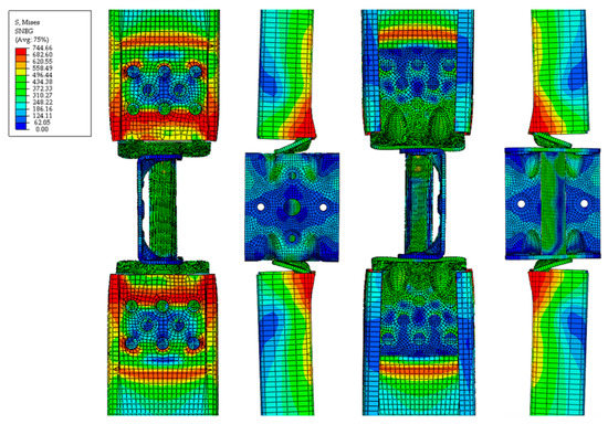
Figure 17.
von Mises stress on the optimised tensile component at the end of simulation obtained by FEA.
Table 8.
Result comparison of the tensile component of the proposed connection.
The optimization of the tensile component revealed that the use of a long nut can increase the initial stiffness and decrease the displacement. The optimised FE model gave an initial stiffness of 7215 N/mm, a maximum load of 39,452 N and a corresponding displacement of 19.79 mm. Plastic deformations started at a load value of about 14,500 N, corresponding to a displacement of about 3 mm, which is a significant improvement. The stresses of the U-connector at the maximum load were lower, with a maximum value slightly higher than the yield stress. This indicates that the tensile load was mainly transmitted through the long nut, which was the main objective of the optimization. Figure 17 illustrates the non-uniform stress distribution on the M12 bolt head and the equivalent plastic strains on the angle bracket, indicating the start of pull-through failure. This type of failure was observed in the previously tested anchored angle bracket connection [19], thus confirming that the capacity of the angle bracket was fully utilised in the optimised connection.
As for the compression component, the von Mises stresses of the UCO FE model are shown in Figure 18 for displacements at maximum load, while the results at the end of the simulation can be seen in Figure 19.
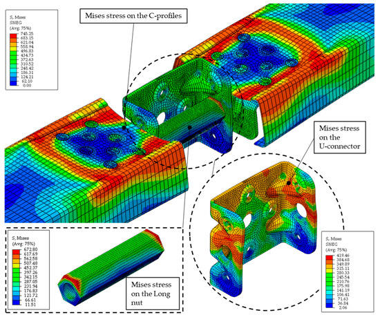
Figure 18.
von Mises stress distribution for the optimised compression component on the C-profiles, a U-connector and the long nut at the ultimate load obtained by FEA.
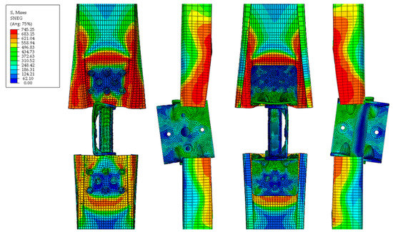
Figure 19.
von Mises stress distribution for the optimised compression component at the end of simulation or 15 mm obtained by FEA.
Optimising the compression component by using a long nut resulted in improved behaviour with an initial stiffness of 7586 N/mm, corresponding to the stiffness of the optimised tension component. The maximum load was 16,456 N at a displacement of 7.03 mm, which is a significant improvement over the previous version. Plastic deformation was observed at about 10,000 N with a corresponding displacement of 1.2 mm. However, due to the eccentricity of the load applied to the angle bracket, a bending moment occurred, causing the flange of the angle bracket to bend. This connection between the angle bracket and the C-profile now transmits a negative moment, causing the web of the C-section to bend, as described earlier with the positive moment [19]. The first row of clinch-pressed connectors now pulls the web of the C-profile downwards, while the outer edge of the angle bracket pushes the web upwards. This leads to high out-of-plane deformations of the flanges of the C-profile, which is visible at a displacement of 15 mm or the end of the simulation. In reality, high deformations of the C-profile’s flanges will be restricted due to the screwed connection between the vertical stud and the bottom chord of the truss beam.
4.4. Comparison of the Optimised Results with the Experimentally Tested and the FEA Obtained Ones
In this section, a comprehensive summary of the results obtained is given and a comparison is made between the optimized tension and compression components. Table 9 and Table 10 show a comparison between the optimized model and the previous version in terms of stiffness, maximum load capacity and the corresponding displacement values. In addition, force-displacement curves for both components are shown in Figure 20. This comparison provides a clear understanding of the behaviour of the optimised components under axial load and their ability to meet the required performance criteria.
Table 9.
Result comparison of the tensile component of the proposed connection.
Table 10.
Result comparison of the compression component of the proposed connection.
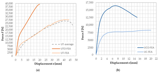
Figure 20.
Force-displacement curve comparison of the optimised connection and previously proposed ones obtained by testing or FEA for (a) tension component and (b) compression component.
The results indicate that the optimization of the proposed connection with the long nut has led to a significant improvement in both the tension and compression components. The load capacity of the FE model of the tension component has increased by 47% compared to the previous design, while the displacement has been reduced by 2.05 times. Furthermore, the initial stiffness of the tension component has improved by 3.6 times. Similar improvements can be observed in the FE model of the compression component: the maximum load capacity was increased by 2.14 times, while the corresponding displacement was reduced by 17% and the initial stiffness was increased by 2.6 times. Additionally, relative elongations of the U-connector had been decreased by 217 times in the tension load scenario and 13.6 times in the compression load scenario. These improvements demonstrate the effectiveness of the long nut optimization in improving the overall performance of the proposed connection.
5. Conclusions
An experimental investigation focused on the behaviour of the U-connector in the tensile component of a proposed connection was conducted. A total of twelve test specimens were tested, all of which exhibited identical behaviour. The connection with the U-connector alone had an average initial stiffness of 1455 N/mm, which was sufficient only for light-load applications. Further investigation of the proposed connection was carried out by numerical analysis. After validating the finite element model with experimental data, a numerical simulation with an assigned compressive load was performed. The numerical model used in this study effectively characterises the behaviour of the tensile component in both the elastic and plastic regions. Although the addition of the failure parameters for the failure region is required, the overall results confirm the high degree of accuracy with which finite element analysis can represent the behaviour of joints in thin-walled sections. The U-connector had a higher initial stiffness, but its load capacity was significantly lower. As a result, the geometry of the proposed connection between the truss beam and the CFS column was further optimised. Based on the results of this study, several conclusions can be drawn regarding the tensile and compressive load components in the proposed connection:
- The results of the experimental tests conducted in this study show that the U-connector exhibits unfavourable behaviour when subjected to loads higher than 7500 N. In particular, the U-connector experienced high plastic deformation, which eventually led to its failure at an average load value of 26,737.56 N with a corresponding displacement of 40.27 mm. The main failure mechanism in the tension component was the tearing of the flange edge of the U-connector, which led to a complete loss of load-bearing capacity.
- By using one longer nut instead of two, a geometric optimisation of the proposed connection was achieved, resulting in significantly more favourable behaviour. The optimised connection design allowed full utilisation of the angle brackets with direct load transfer through the long nut. This behaviour of the optimised connection is similar to that of the previously tested anchored angle bracket.
- Although the numerical simulation carried out in this study gave a slightly higher ultimate load of 39,452.40 N, the load before the start of the pull-through failure, it is recommended to use the ultimate load value that was experimentally obtained in the previous work [19].
- The numerical analysis of the optimised tensile component carried out in this study supports the original assumption that a non-uniform stress distribution occurs under the bolt head. This is due to the greater stiffness of the upper part of the flange of the angle bracket, which leads to a concentration of stresses in this area.
- Numerical analysis of the compression component showed a lower load capacity, with most of the deformation occurring in the U-connector. As the deformation increased, contact occurred between the edge of the C-profile and the U-connector, resulting in damage to the C-section.
- The proposed compression component without the long nut is only suitable for light-load applications involving truss beams with compression forces not exceeding approximately 5000 N.
- The use of a long nut in the compression component significantly reduced the deformations in the U-connector and allowed the angle brackets to be fully utilised with an ultimate load value of 16,456.30 N. However, the bending of the angle brackets was the main failure mechanism leading to high plastic deformation of the C-profile flanges. Future work needs to confirm that this effect is insignificant as the vertical element of the truss beam constrains these flanges.
Author Contributions
Conceptualization, L.L. and P.K.; methodology, L.L. and P.K.; software, L.L.; validation, L.L.; formal analysis, L.L., P.K., A.B. and I.P.; investigation, L.L. and P.K.; resources, L.L. and P.K.; data curation, L.L.; writing—original draft preparation, L.L. and P.K.; writing—review and editing, L.L. and P.K.; visualization, L.L. and A.B.; supervision, P.K. and I.P.; project administration, P.K.; funding acquisition, P.K. All authors have read and agreed to the published version of the manuscript.
Funding
This research was funded by the UNIRI INOVA project “Innovative connector for connecting structural elements made of thin-walled steel C-profiles” with the financial support of the University of Rijeka and industrial project “Prefabricated buildings of almost zero energy produced in an industrial way”, Grant no. KK.01.2.1.02.0046, financed from the European Fund for Regional Development.
Data Availability Statement
The data presented in this study are available on request from the corresponding author.
Acknowledgments
The authors would like to thank the company Tehnoplast profili d.o.o. for production specimens and test tools.
Conflicts of Interest
The authors declare no conflict of interest.
References
- Liang, H.; Roy, K.; Fang, Z.; Lim, J.B.P. A Critical Review on Optimization of Cold-Formed Steel Members for Better Structural and Thermal Performances. Buildings 2022, 12, 34. [Google Scholar] [CrossRef]
- Fan, J.; Li, T.; Sun, P.; Wang, D.; Chen, X. Experimental analysis of the truss-to-column connection in a modularized prefabricated steel structure. J. Build. Eng. 2022, 49, 104115. [Google Scholar] [CrossRef]
- Di Lorenzo, G.; De Martino, A. Earthquake response of cold-formed steel-based building systems: An overview of the current state of the art. Buildings 2019, 9, 228. [Google Scholar] [CrossRef]
- Lennon, R.; Pedreschi, R.; Sinha, B.P. Comparative study of some mechanical connections in cold formed steel. Constr. Build. Mater. 1999, 13, 109–116. [Google Scholar] [CrossRef]
- Davies, J.M. Recent research advances in cold-formed steel structures. J. Constr. Steel Res. 2000, 55, 267–288. [Google Scholar] [CrossRef]
- Usefi, N.; Ronagh, H.; Sharafi, P. Lateral performance of a new hybrid CFS shear wall panel for mid-rise construction. J. Constr. Steel Res. 2020, 168, 106000. [Google Scholar] [CrossRef]
- Ayatollahi, S.R.; Usefi, N.; Ronagh, H.; Izadinia, M.; Javaheri, M.R. Performance of gypsum sheathed CFS panels under combined lateral and gravity loading. J. Constr. Steel Res. 2020, 170, 106125. [Google Scholar] [CrossRef]
- Kyprianou, C.; Kyvelou, P.; Gardner, L.; Nethercot, D.A. Characterisation of Material and Connection Behaviour in Sheathed Cold-Formed SteelWall Systems—Part 2: Analytical Modelling. Structures 2021, 30, 1184–1199. [Google Scholar] [CrossRef]
- Wang, J.; Wang, W.; Xiao, Y.; Guo, L. Cyclic behavior tests and evaluation of CFS truss composite floors. J. Build. Eng. 2021, 35, 101974. [Google Scholar] [CrossRef]
- Dizdar, Ç.; Baran, E.; Topkaya, C. Strength and stiffness of floor trusses fabricated from cold-formed steel lipped channels. Eng. Struct. 2019, 181, 437–457. [Google Scholar] [CrossRef]
- Tian, L.-M.; Kou, Y.-F.; Hao, J.-P.; Zhao, L.-W. Flexural performance of a lightweight composite floor comprising cold-formed steel trusses and a composite mortar slab. Thin-Walled Struct. 2019, 144, 106361. [Google Scholar] [CrossRef]
- Bondok, D.H.; Salim, H.A. Failure Capacities of Cold-Formed Steel Roof Trusses End-Connections. Thin-Walled Struct. 2017, 121, 57–66. [Google Scholar] [CrossRef]
- Obeydi, M.; Daei, M.; Zeynalian, M.; Abbasi, M. Numerical Modeling on Thin-Walled Cold-Formed Steel Clip Angles Subjected to Pull-out Failures. Thin-Walled Struct. 2021, 164, 107716. [Google Scholar] [CrossRef]
- Wang, X.; Yuan, X.; Zeng, H.; Li, T.; Liang, Y.; Gao, X.; Yu, Y. Bearing capacity and failure mode of a light-steel tubular K-joint connected by a novel U-shape connector. Appl. Sci. 2021, 11, 8587. [Google Scholar] [CrossRef]
- Wang, X.; Liu, F.; Li, X.; Li, T.; Xu, X.; Shui, Z.; Wu, H. Static Bearing Capacity Investigation of a Novel Prefabricated Light-Steel Beam–Column Connection. Appl. Sci. 2022, 12, 4387. [Google Scholar] [CrossRef]
- Wang, X.; Wang, J.; Xu, M.; Tang, Y.; Li, D.M.; Wang, Q.; Cai, S.; Hu, S.Y.; Liao, C.Y.; Feng, J.S. Prefabricated tubular light roof truss assembled with screwed novel modular connectors: Full-scale test and FE modelling. Thin-Walled Struct. 2023, 182, 110229. [Google Scholar] [CrossRef]
- Tankova, T.; Craveiro, H.; Silva, L.C.; Ribeiro, F.F.; Simões, R.; Martins, C.; Costa, R.; Simões da Silva, L. Behaviour of plug-and-play joints between RHS columns and CFS trusses. Structures 2022, 41, 1719–1745. [Google Scholar] [CrossRef]
- Da Silva, L.S.; Silva, L.C.; Tankova, T.; Craveiro, H.D.; Simoes, R.; Costa, R.; D’Aniello, M.; Landolfo, R. Performance of modular hybrid cold-formed/tubular structural system. Structures 2021, 30, 1006–1019. [Google Scholar] [CrossRef]
- Lukačcević, L.; Krolo, P.; Bakran, A. Experimental Investigation of Novel Angle Bracket Connection in Cold-Formed Steel Structures. Buildings 2022, 12, 1115. [Google Scholar] [CrossRef]
- Abaqus/CAE User’s Manual, version 6.7; ABAQUS Inc.: Pawtucket, RI, USA, 2007.
- DIN 6921; Hexagon Flange Bolts. International Organization for Standardization: Geneva, Switzerland, 1983.
- EN 1661; Hexagon Nuts with Flange. European Committee for Standardization, CEN: Brussels, Belgium, 1996.
- ISO 6892-1:2019; Metallic Materials—Tensile Testing—Part 1: Method of Test at Room Temperature. The International Organization for Standardization: Geneva, Switzerland, 2019.
- Bolted Joint Analysis. Mechanicalc.com. Available online: https://mechanicalc.com/reference/bolted-joint-analysis (accessed on 8 February 2023).
- Pang, X.-P.; Hu, Y.; Tang, S.-L.; Xiang, Z.; Wu, G.; Xu, T.; Wang, X.-Q. Physical properties of high-strength bolt materials at elevated temperatures. Results Phys. 2019, 13, 102156. [Google Scholar] [CrossRef]
- Quan, G.; Ye, J.; Li, W. Computational modelling of Cold-formed steel lap joints with screw fasteners. Structures 2021, 33, 230–245. [Google Scholar] [CrossRef]
- Schafer, B.W.; Peköz, T. Computational modeling of cold-formed steel: Characterizing geometric imperfections and residual stresses. J. Constr. Steel Res. 1998, 47, 193–210. [Google Scholar] [CrossRef]
- EN 10277:2018; Bright Steel Products—Technical Delivery Conditions. European Committee for Standardization, CEN: Brussels, Belgium, 2018.


Disclaimer/Publisher’s Note: The statements, opinions and data contained in all publications are solely those of the individual author(s) and contributor(s) and not of MDPI and/or the editor(s). MDPI and/or the editor(s) disclaim responsibility for any injury to people or property resulting from any ideas, methods, instructions or products referred to in the content. |
© 2023 by the authors. Licensee MDPI, Basel, Switzerland. This article is an open access article distributed under the terms and conditions of the Creative Commons Attribution (CC BY) license (https://creativecommons.org/licenses/by/4.0/).