Article

A Comparison of Load Distribution Methods at the Node and Internal Force Analysis of the Lattice Beam Based on the Winkler Foundation Model

1
School of Resource Environment and Safety Engineering, University of South China, Hengyang 421001, China
2
School of Civil Engineering, University of South China, Hengyang 421001, China
3
School of Resources and Safety Engineering, Central South University, Changsha 410012, China
*
Author to whom correspondence should be addressed.
Buildings 2023, 13(7), 1731; https://doi.org/10.3390/buildings13071731
Submission received: 17 May 2023 / Revised: 30 June 2023 / Accepted: 5 July 2023 / Published: 7 July 2023
(This article belongs to the Section Building Structures)

Abstract

:
As a new type of retaining structure, lattice beams with tie-back anchor cables have been increasingly used in slope reinforcement and have achieved improved prevention effects. However, the simplified load distribution method (SLDM) at the node, which is the theoretical basis of internal force analysis for lattice beams, is not perfect at present. An alternative new load distribution method (NLDM) at the node based on the force method for the lattice beam was therefore introduced in this paper. Taking into account the loads acting on other nodes of the beams in both directions and according to the static equilibrium condition and deformation compatibility condition at the nodes, NLDM assigns the loads acting on the nodes to the cross beams and vertical beams, respectively, by constructing and solving a system of linear equations. In order to verify the superiority of NLDM, a case of slope reinforced by a lattice beam was introduced in this paper, and the load distribution of the nodes under the design condition was carried out based on both methods. Then, the deflections at the nodes of the lattice beam resting on the Winkler foundation, loaded with the known loads, were analyzed by the superposition method. The results of the deformation analysis showed that the deflections at the same nodes of the beams in both directions based on NLDM were almost equal, thus demonstrating the superiority of NLDM in terms of deformation compatibility. In addition, a comparative analysis of the theoretical bending moments of the lattice beam under the design and the actual working conditions based on both methods was also carried out. The results of the bending moment analysis showed that the bending moments of the cross beam differed significantly in the middle third of the beam length, while the bending moments of the vertical beams differed significantly at the beam sections where the maximum bending moments are located, and the theoretical bending moments under the actual working condition were in relatively good agreement with the measured values. Consequently, NLDM for the lattice beam was self-consistent in terms of the deformation compatibility at the node, and therefore the introduction of this new method provides an important theoretical basis for the accurate internal force analysis of lattice beams.

1. Introduction

The lattice beam (also called frame beam or concrete grillage) with anchor cables is a new type of in-situ retaining structure that has been proposed with the development of retaining structures in the past four decades in China [1,2,3,4,5,6,7]. It is a flexible retaining structure comprising a reinforced concrete lattice beam placed on the slope surface, cables anchored in the stable stratum, and the slope soil behind the wall (see Figure 1). The three components of the lattice beam slope anchoring system can form a self-balancing system that maintains long-term slope stability. After the construction of the lattice beam, sprayed concrete, dry stone, or grass [8,9] is placed on the slope surface between the frame beams to mitigate slope surface erosion and provide local slope stability. In this way, a lattice beam is also a kind of environment-friendly and versatile retaining structure that takes into account both the overall and local stability of the slope. In China, the lattice beam placed on the slope surface is a reinforced concrete frame beam structure, which is mainly made of concrete with a compressive strength of not less than 25 MPa (C25), the cross-sectional area of the beams is not less than b × h = 250 mm × 300 mm, and the distance between the adjacent beams in both directions should be less than 4.0 m [10].
Since the successful application of lattice beams in highway slopes in the 1980s in China, the lattice beam slope anchorage system has been widely used for the reinforcement of various high and steep man-made slopes [11,12,13] or landslides [14,15] due to its light weight, flexibility, and good seismic performance [16,17,18,19,20]. Similar to the design of the traditional slope retaining structure, in addition to obtaining the parameters such as displacement, stress, strain, and FOS of the slope by numerical analysis [21,22,23], the design of the lattice beam slope anchorage system requires accurate calculation of the internal forces such as bending moment and shear force of the lattice beam. Only on this basis, the steel bar configuration in the beams running in both directions can be reasonably determined in advance of the slope construction. Although it is widely used in slope treatment, the analysis of lattice beams, especially the analysis theory for the internal force of lattice beams, is still imperfect at present, so the theoretical analysis of this technique lags behind engineering practice, leading to several cases of structural damage of lattice beam (see Figure 2).
In terms of the slope reinforcement mechanism (see Figure 3), the prestressing forces acting on the nodes are transferred to the slope body by means of the lattice beam placed on the slope surface to change the stress states of the slope and increase the resisting force on the potential sliding surface of the slope, thus achieving the goal of long-term slope stability. In terms of the internal force analysis for the lattice beam (see Figure 3), as a facing structure on the slope surface, the lattice beam can be considered as a spatial frame beam resting on an elastic foundation and subjected to anchoring forces at the nodes. Therefore, in the conventional internal force analysis of a lattice beam, the prestressing force acting on the node of the lattice beam is considered a transverse concentrated load, which can be assigned to the cross beam and vertical beam, respectively, according to the static equilibrium condition and deformation compatibility condition at the node. Once the unknown forces assigned to the vertical beams and cross beams of the lattice beam system are obtained, the lattice beam, as a spatially load-bearing facing structure, can be decomposed into a series of one-dimensional beams resting on an elastic foundation. The internal forces of these one-dimensional beams loaded with the known loads can be easily calculated. Before analyzing the internal forces for these one-dimensional beams disassembled from the whole lattice beam system, the first and foremost problem is how to obtain the loads assigned to the nodes of the beams in both directions, in other words, how to rationally assign the concentrated loads acting on the nodes of lattice beam to the cross beams and vertical beams, respectively.
At present, SLDM is widely used in China for the load distribution at the node of the lattice beam [24,25], and this philosophy is also recommended for use in the Chinese standard [26]. It ignores the torque effects of the beams running in one direction caused by the bending moments of the beams running in the other direction and does not consider the deformation at a node caused by loads acting on other nodes of the beams in both directions, SLDM assumes that the beams passing through the nodes are infinite long beams or semi-infinite long beams supported by Winkler foundation, and then, according to the static equilibrium condition and the deformation compatibility condition at the nodes, the loads acting on the nodes are assigned to the cross beams and vertical beams passing through the nodes, respectively. In fact, SLDM for lattice beams mainly has the following two main shortcomings: (1) the subjective assumption that the cross beam and vertical beam passing through a node are infinite long beams or semi-infinite long beams is inconsistent with the fact that most of the beams in both directions are finite long beams resting on Winkler foundation; (2) it is impossible to consider the influence of the loads acting on other nodes of the cross beam and vertical beam on the deformation at the node to be load-distributed, which may lead to deformation incompatibility at the nodes.
In order to overcome some disadvantages of SLDM based on the above assumptions, an NLDM based on the force method was introduced in this paper. This new method does not make any subjective assumptions about the types of the cross beams and vertical beams resting on the Winkler foundation, Instead, it can take into account the influence of the loads acting on other nodes of the beams running in both directions, and can distinguish the difference in stiffness of the beams in both directions relative to the ground. According to the static equilibrium condition and the deformation compatibility condition at the nodes, by constructing and solving a system of linear equations, NLDM can rationally distribute the loads acting on the nodes to the cross beams and vertical beams, respectively.
The structure of this paper is as follows: First, based on Winkler foundation theory, SLDM, and NLDM were introduced in detail in this paper; then, a case of slope reinforced by a lattice beam with three cross beams and three vertical beams was introduced, and both load distribution methods were used to assign the design loads acting on the nodes of the lattice beam to the cross beams and vertical beams, respectively, and the superiority of NLDM was verified by the deformation compatibility condition at the same nodes; Finally, the theoretical bending moments of the cross beams and vertical beams supported by Winkler foundation and loaded by the known loads obtained by both load distribution methods were analyzed in comparison, and, furthermore, a comparative analysis was also performed between the theoretical bending moments and the measured values under the accrual working condition.

2. Load Distribution Methods at the Node for Lattice Beam

2.1. Simplified Load Distribution Method

The SLDM at the node for the lattice beam is derived from the load distribution method for the interconnected beam in the foundation engineering textbook [27]. In this method [28,29], the nodes are first divided into three basic types: the corner nodes, edge nodes, and internodes according to their positions in the plane of the lattice beam; then, the cross beams and vertical beams through the nodes are considered as infinite long beams or semi-infinite long beams on Winkler foundation, and the prestressing of the anchor cable acting on each node is assigned to the cross beam and vertical beam, respectively, according to the static equilibrium condition and deformation compatibility condition of the node (see Figure 4); finally, the whole lattice beam is decomposed into several one-dimensional beams on Winkler foundation for the internal force analysis.

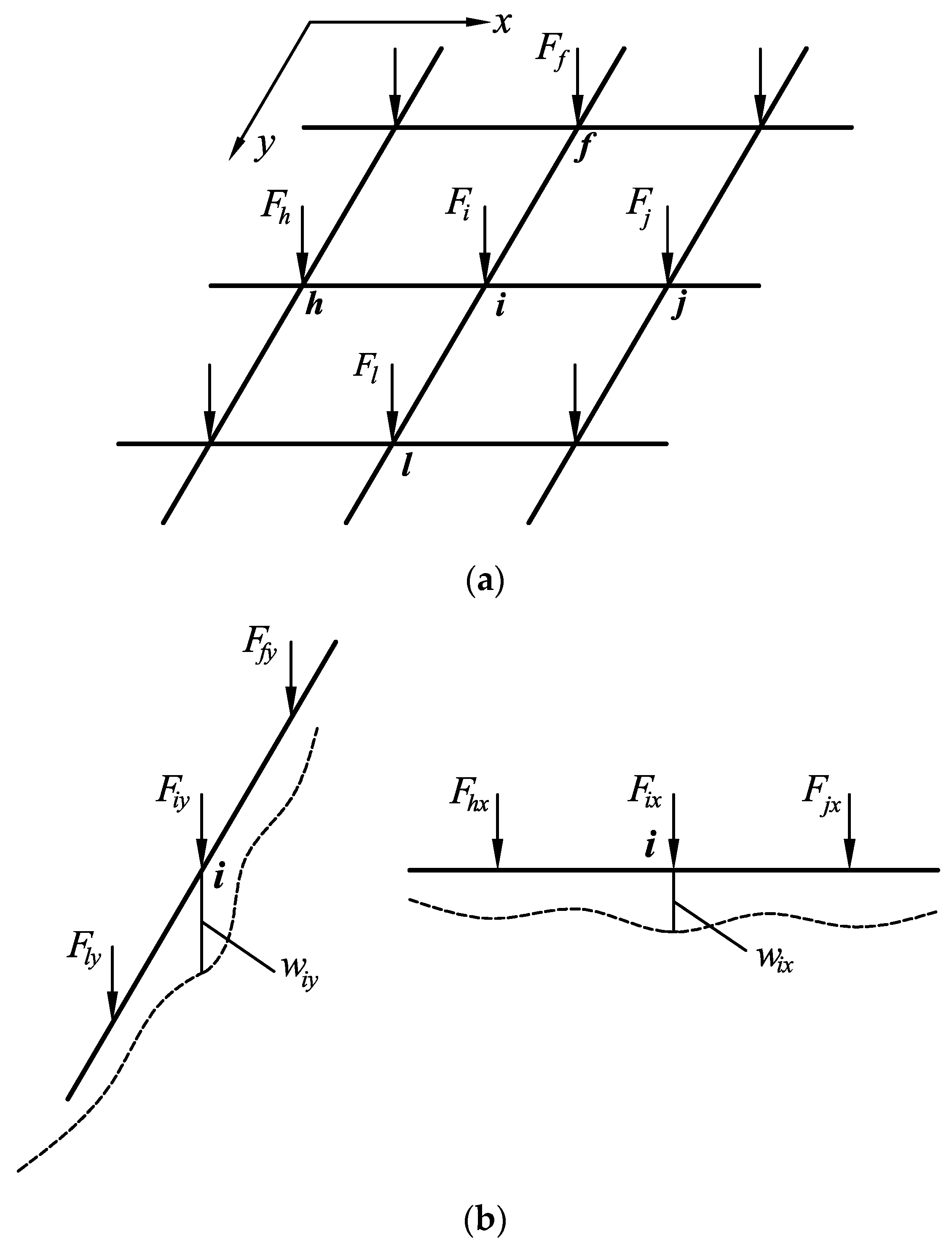
2.1.1. Load Distribution Assumptions

When evaluating the distribution of a concentrated load at each node based on SLDM, the following two conditions below must first be satisfied:
(a)
The static equilibrium condition: the sum of the loads assigned to the cross beam and the vertical beam at a node should be equal to the total load acting on the node;
(b)
The deformation compatibility condition: the deflection of the cross beam at a node should be equal to that of the vertical beam at the same node.
Based on the above basic conditions, as shown in Figure 4b, there is a concentrated load Fi acting on an arbitrary node i of the lattice beam, and the Fi acting on the node i is assigned to the cross beam in the x-direction and the vertical beam in the y-direction as Fix and Fiy at the node i, respectively, according to the static equilibrium condition:
F i = F i x + F i y
For the deformation compatibility condition, the deflection wix induced only by Fix at the node i of the cross beam in the x direction and the deflection wiy induced only by Fiy at the node i of the vertical beam in y direction are required to be equal:
w i x = w i y
To simplify the load distribution model, the cross beams and the vertical beams are assumed to be hinged at the nodes. In this way, the bending moment in one beam is supported by the beam itself, and the bending moments of the beams in one direction do not induce deformation at the nodes of the beams running in the other direction.

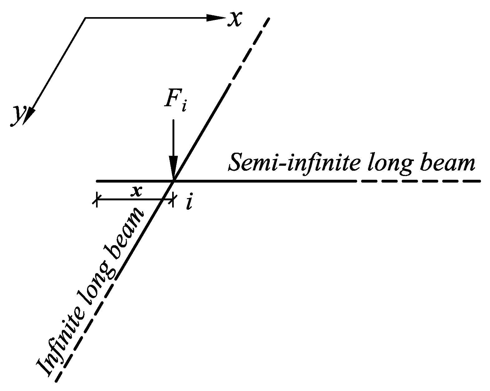
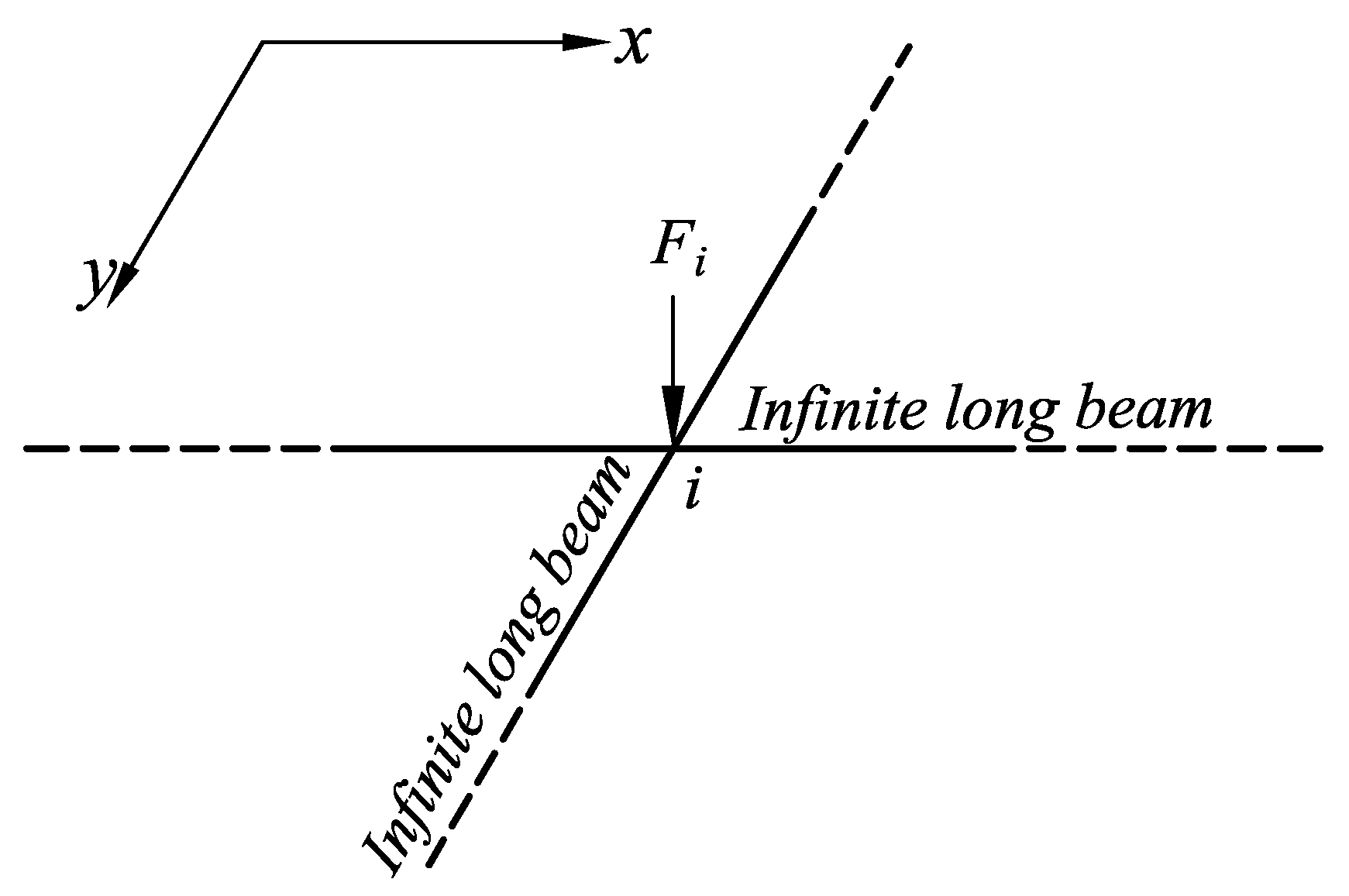
2.1.2. Theoretical Basis of SLDM

In the node deformation analysis, SLDM usually assumes that the cross beam and the vertical beam passing through a node are infinite long beams or semi-infinite long beams supported by the Winkler foundation. This section focuses on the superposition method for deflection analysis of a semi-infinite long beam supported by the Winkler foundation [30].
As shown in Figure 5, there is a concentrated force F0 acting on the section O of the semi-infinite long beam (beam I) with a left extension length of x (x < π/λ, where λ is the flexibility eigenvalue of the beam) from section O and an extension of infinite length in the right direction. The deflection of section O could be calculated according to the method of superposition of the infinite long beam (beam II). The given semi-infinite long beam is extended infinitely in the left direction so that the given beam (beam I) becomes part of an infinitely long beam (beam II). In order to use the superposition method to calculate the deflection at section O of an infinitely long beam supported by the Winkler foundation, an unknown vertical concentrated force FA and an unknown concentrated moment MA should be applied to section A of the infinitely long beam. The purpose of applying end-conditioning forces FA and MA on section A of the infinite long beam is to compensate the shear force and bending moment generated by the given load F0 acting on the infinite long beam, so that the total shear force and the total bending moment at section A of the infinite long beam become zero, which can reflect the actual boundary conditions of the semi-finite long beam.
According to the force boundary conditions at section A of the infinite long beam, there are
F A S 4 + M A 2 + F 0 2 C x = 0 F A 2 M A 2 S + F 0 2 D x = 0
where,
S = 1 / λ = 4 E I / k b 4
C x = e λ x ( cos λ x sin λ x )
D x = e λ x cos λ x
λ—Flexibility eigenvalue of the beam (m−1);
S—Characteristic length (m);
E—Young’s modulus of the beam (kPa);
I—Moment of inertia of the beam section (m4);
k—Modulus of subgrade reaction (kN/m3);
b—Width of the beam (m).
The end-conditioning forces FA and MA can be obtained by solving Equation (3):
F A = F 0 ( C x + 2 D x ) M A = F 0 S ( C x + D x )
Under the combined action of the given load F0 and the end-conditioning forces FA and MA, the deflection at the section O of the semi-infinite long beam (beam I) can be obtained by the method of superposition of the infinite long beam (beam II) supported by the Winkler foundation:
ω o = F 0 2 k b S + F A 2 k b S A x + M A k b S 2 B x = F 0 2 k b S 1 + ( C x + 2 D x ) A x 2 ( C x + D x ) B x = F 0 2 k b S 1 + e 2 λ x ( 1 + 2 cos 2 λ x 2 cos λ x sin λ x ) = F 0 2 k b S Z x
where,
A x = e λ x ( cos λ x + sin λ x )
B x = e λ x sin λ x
Z x = 1 + e 2 λ x ( 1 + 2 cos 2 λ x 2 cos λ x sin λ x ) .
From Equation (5), when the left extension length of x = 0 (a semi-infinite end-loaded beam), then Zx = 4, and thus the deflection at section O of the semi-infinite long beam wo = 2F0/kbS. On the other hand, if the left extension length of x = ∞ (an infinitely long beam), then Zx = 1, and thus the deflection at section O of the infinite long beam wo = F0/2kbS.

2.1.3. Node Classification and Load Distribution Equations

When the distances between the other nodes and the concerned node are more than 1.8/λ, it’s believed that the deflection of the concerned node is only related to the load acting on the concerned node itself and the loads acting on other nodes have little influence on the deflection of the node to be load distributed. Therefore, based on the above assumption, the deflections wix and wiy of the beams passing through the node i can be greatly simplified by ignoring the effect of the loads acting on other nodes of the beams. As a result, depending on the distances between the nodes and the beam ends, the beams passing through a node belong to different types (the finite long beam, the semi-infinite long beam) based on SLDM. To further improve the practicability of SLDM, according to the positions of the nodes in the whole lattice beam system, the nodes of the lattice beam can be divided into three categories: (a) the corner node, (b) the edge node, and (c) the inner node. Based on the type of the nodes, the beams in both directions passing through a node are assumed to be infinite long beams or semi-infinite long beams supported by the Winkler foundation. Then, the load distribution formulas for the lattice beam are derived based on the types of the nodes.

The Corner Node

A typical corner node (see Figure 6) of a lattice beam consists of two beams running in x and y directions, and the lengths of both beams extending outward from the node i are x and y, respectively. The two beams running in x and y directions can be considered as semi-infinite long beams supported by a Winkler foundation, so the deflections of both beams at node i can be obtained according to Equation (5):
ω i x = F i x Z x 2 k b x S x ω i y = F i y Z y 2 k b y S y
where, Fix and Fiy are the loads assigned to the beams in the x and y directions by the total concentrated load Fi acting on the corner node i, respectively, wix induced only by Fix and wiy induced only by Fiy are the deflections at the nodes i of the beams in both directions, respectively.
According to the static equilibrium condition and the deformation compatibility condition at node i, the concentrated load distribution equations at the corner node based on SLDM can be easily obtained:
F i x = Z y b x S x Z y b x S x + Z x b y S y F i F i y = Z x b y S y Z y b x S x + Z x b y S y F i

The Edge Node

Figure 7 shows a typical edge node of a lattice beam and the beam in the x-direction extends outward from node i with a length of x. The beam in the x-direction is assumed to be semi-infinitely long, while the beam in the y-direction is assumed to be infinitely long. From Equation (5), Zy = 1, and therefore the deflections of both beams at the edge node i can be obtained according to Equation (5):
ω i x = F i x Z x 2 k b x S x ω i y = F i y 2 k b y S y
According to the static equilibrium condition and deformation compatibility condition at the edge node i, the concentrated load distribution equations at the edge node can be easily obtained:
F i x = b x S x b x S x + Z x b y S y F i F i y = Z x b y S y b x S x + Z x b y S y F i

The Inner Node

Figure 8 shows a typical inner node of a lattice beam and both beams running in the x and y directions can be regarded as infinite long beams supported by the Winkler foundation, then Zx = Zy = 1, so the deflections for both beams at the inner node i can be obtained according to Equation (5):
ω i x = F i x 2 k b x S x ω i y = F i y 2 k b y S y
According to the static equilibrium condition and the deformation compatibility condition at the inner node i, the concentrated load distribution equations at the inner node can be easily obtained:
F i x = b x S x b x S x + b y S y F i F i y = b y S y b x S x + b y S y F i

2.1.4. Evaluation of the SLDM

In engineering practice, when the slope is reinforced by a lattice beam with prestressing anchor cables, the distances from the nodes to the beam ends are generally less than π/λ, as a result, most of the cross beams and vertical beams are finite long beams. As Hetenyi [31] stated that when the beam length l > π/λ (group III: long beam), the load applied at one end will have a negligible effect on the other end, which is assumed to be infinitely far away, and this assumption can greatly simplify the calculation. Based on the above assumptions, for the classification of the beams on the Winkler foundation, it is important to consider not only the relative stiffness of the beam to the foundation but also whether the location of the load will have a non-negligible effect on the beam ends. Therefore, SLDM at the node of the lattice beam assumes that the beams passing through a node are semi-infinite long beams (see Figure 6 and Figure 7) or infinite long beams (see Figure 7 and Figure 8), which is not consistent with the actual situation. In addition, when assigning the load acting on a node to the cross beam and the vertical beam, the assumption is made that the deflection at the node i of the cross beam caused only by Fix is equal to that of the vertical beam caused only by Fiy is taken into account, which is also inconsistent with the fact that the loads acting on the nodes other than the node i of the beams will also induce deflections at the node i. In fact, there is no infinitely long beam in the real sense, and the loads acting on other nodes of the beam will inevitably affect the deformation at the node to be concerned. Even if both the cross beam and the vertical beam passing through an inter-node are all assumed to be infinite long beams based on SLDM, the loads assigned to the cross beam and the vertical beam at the inter-node cannot be equal due to the difference in stiffness of the beams in both directions relative to the ground.
In summary, SLDM cannot distinguish the difference in stiffness between the beams running in both directions relative to the ground and neglects the contributions of the loads acting on other nodes of the beams running in both directions to the deformation of the concerned node, which can lead to large errors in assigning loads acting on a node to beams in different directions.

2.2. Introduction to the NLDM

2.2.1. The New Load Distribution Model Based on the Force Method

In order to address some of the drawbacks of SLDM, an NLDM, which is also adapted from the load distribution at the node for the interconnected beam in foundation engineering textbooks [32,33], was introduced in this paper for the load distribution at the node of lattice beam.
As shown in Figure 9, a lattice beam resting on an elastic foundation is subjected to concentrated loads at the nodes. A concentrated load Fi acting on any node i is assigned to the cross beam and the vertical beam with Fix and Fiy, respectively. Obviously, if the lattice beam wants to work safely and reliably at node i, just like SLDM, it is necessary to make node i satisfy the static equilibrium condition and the deformation compatibility condition. Specifically, the deflection wix at the node i of the cross beam caused by the loads Fhx, Fix, and Fjx assigned to the cross beam by Fh, Fi, and Fj should be equal to the deflection wiy at the node i of the vertical beam caused by the loads Fly, Fiy and Ffy assigned to the vertical beam by Fl, Fi, and Ff.

2.2.2. Analysis of the Deflection at the Nodes and Formation of a System of Linear Equations
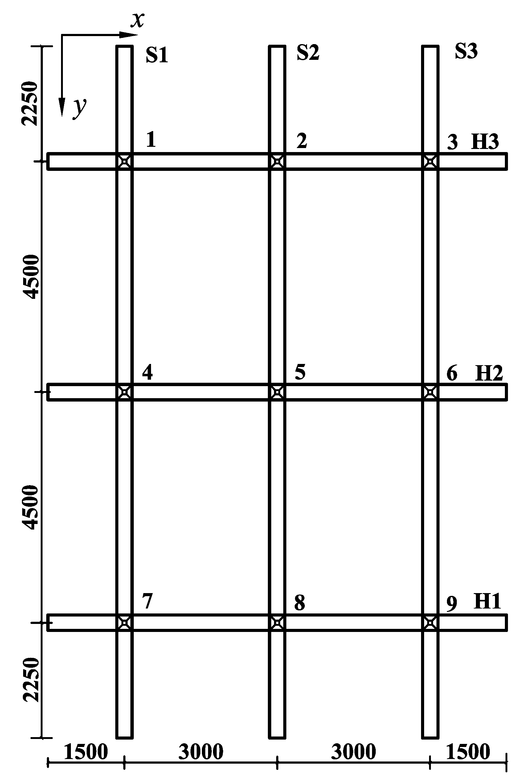
There is a cross beam (see Figure 9b) running in the x-direction disassembled from the lattice beam supported by the Winkler foundation, and this cross beam is subjected to the unknown loads Fhx, Fix, and Fjx. Assuming that only a unit load Fix = 1 kN acts on the node i of the cross beam, the deflection of this cross beam at the node i is δxii (m) while assuming that only a unit load Fjx = 1 kN acts on the node j of this cross beam, the deflection of the cross beam at the node i is δxij (m). Therefore, the total deflection at the node i of the cross beam under the combined action of all the unknown loads Fhx, Fix, and Fjx acting on the nodes h, i, and j of this cross beam is:
w i x = F h x δ i h x + F i x δ i i x + F j x δ i j x
Similarly, for the vertical beam (see Figure 9b) disassembled from the lattice beam passing through node i, the total deflection at node i due to the unknown loads Fly, Fiy, and Ffy is given by
w i y = F l y δ i l y + F i y δ i i y + F f y δ i f y
Similar to SLDM, according to the static equilibrium condition (Fix + Fiy = Fi) and deformation compatibility condition (wix = wiy) at the nodes, NLDM based on the force method requires the construction of a system of linear equations with 2n (n is the total number of nodes of a lattice beam) unknowns, and the 2n unknown loads assigned to the nodes of the beams in both directions can be obtained by solving the system of linear equations.
Unlike the node-by-node load distribution model based on SLDM, considering the interaction between the loads acting on the beams in both directions, by constructing and solving a system of linear equations, NLDM can distribute the loads acting on the nodes of a lattice beam to the cross beams and vertical beams at the same time. By using NLDM, the lattice beam system should first be decoupled and disassembled into a series of one-dimensional beams resting on the Winkler foundation beforehand, then the deflections at the nodes of each beam under the unit loads can be found one by one by using the superposition method, and, finally, a system of linear equations with 2n unknown loads based on the force method can be constructed according to the coupling of the static equilibrium condition and the deformation compatibility condition at the nodes. By solving the system of linear equations, all the loads assigned to the nodes of the cross beams and vertical beams can be obtained, and each beam supported by the Winkler foundation and loaded with the known loads at the nodes can be analyzed separately by the superposition method.
In the slope reinforcement, the lattice beam is usually a symmetrical structure in both x and y directions, and the loads acting on the nodes of the lattice beam are usually equal, so the number of unknown loads can be greatly reduced, which provides convenience for the load distribution at the nodes by using NLDM.

3. A Case Study

In this paper, a slope reinforced by a lattice beam from the literature [34] was presented, and segment AB of the slope was taken for comparative analysis based on both methods. The upper slope of segment AB was reinforced by a lattice beam with nine prestressed anchor cables acting on the nodes. Each lattice beam consists of three cross beams (denoted as H1, H2, and H3 from bottom to top) and three vertical beams (denoted as S1, S2, and S3 from left to right) with rectangular beam sections, 300 mm in width and 300 mm in height. The plane dimensions of the lattice beam to be studied are shown in Figure 10. Under the design condition, the anchoring force acting on each node of the lattice beam is 230 kN.
The physical and mechanical parameters of the lattice beam and the slope soil are used to distribute the loads acting on the nodes of the lattice beam, as shown in Table 1.

4. Results and Discussion

4.1. Results under the Design Condition

4.1.1. Load Distributions under the Design Condition

To obtain the internal forces of the cross beams and vertical beams, it is necessary to allocate the total concentrated forces acting on the nodes to the cross beams and the vertical beams, respectively. Based on the load distribution methods mentioned above, the static equilibrium condition at each node under the design condition can be expressed as follows:
F i = P i cos ( 90 ° α θ ) = F i x + F i y = 229.52 kN
where, Pi = 230 kN and Fi = 229.52 kN are the total anchoring force of the anchor cable acting on the node i of the lattice beam under the design condition and the component of the total anchoring force perpendicular to the slope surface, respectively; α = 41.3° and θ = 45° are the angle of the design slope and the inclination of the anchor cable to the horizontal plane, respectively; Fix and Fiy are the loads assigned by Fi to the cross beams and the vertical beams, respectively.
According to the static equilibrium condition and the deformation compatibility condition at the nodes of the lattice beam system under the design condition, NLDM makes it possible to write the following system of 9 × 2 linear equations as follows:
F 1 x + F 1 y = F 1 F 2 x + F 2 y = F 2 F 9 x + F 9 y = F 9 F 1 x δ 11 x + F 2 x δ 12 x + F 3 x δ 13 x = F 1 y δ 11 y + F 4 y δ 14 y + F 7 y δ 17 y F 1 x δ 21 x + F 2 x δ 22 x + F 3 x δ 23 x = F 2 y δ 22 y + F 5 y δ 25 y + F 2 y δ 28 y F 7 x δ 97 x + F 8 x δ 98 x + F 9 x δ 99 x = F 3 y δ 93 y + F 6 y δ 96 y + F 9 y δ 99 y
There are 18 linear equations and 18 unknown loads in this system, and the unknown loads can be easily obtained by solving the system of the linear Equation (15). In fact, the calculation of the coefficients of the last nine equations of the system is so tedious and time-consuming that they can be obtained using the symbolic computing system Mathematica [35].
Based on both load distribution methods, the load distributions at the nodes of the lattice beam were performed, and the results are shown in Table 2.
It can be seen from Table 2 that the results obtained based on both load distribution methods are quite different. Compared with SLDM, NLDM assigns the total loads acting on the nodes of the lattice beam to the cross beam with smaller values but to the vertical beam with larger values due to the different spans of the cross beams and vertical beams in both directions, and NLDM distributes the total loads at the nodes more evenly to the cross beams and vertical beams. Taking node 5 as an example to illustrate the reasons, intuitively, the cross beam (H2) and the vertical beam (S2) passing through node 5 have different lengths in both directions, so the total load acting on node 5 should be assigned to different values to the cross beams and vertical beams, respectively. However, SLDM assumes that both the cross beam (H2) and the vertical beam (S2) passing through node 5 are all infinite long beams and ignores the influence of the loads acting on other nodes (nodes 4 and 6 of the H2 and the nodes 2 and 8 of the S2, respectively) of the beams in both the x and y directions. Thus, according to the static equilibrium condition and the deformation compatibility condition at node 5, the load acting on node 5 is equally distributed to the cross beam and the vertical beam, respectively, based on SLDM. On the other hand, NLDM does not make any subjective assumptions about the types of beams passing through node 5 and takes into account the effects of the loads acting on node 5 as well as the loads on nodes other than node 5, then the superposition method of is adopted to satisfy the condition of “real deformation compatibility” at the node 5, thus the load acting on the node 5 is assigned to different values to the cross beam (H2) and the vertical beam (S2) at the node 5, receptively. In fact, the distances between node 5 and the adjacent nodes (node 2 and node 8) of the vertical beam S2 are larger than those between node 5 and the adjacent nodes (node 4 and node 6) of the cross beam H2, that is, the contributions of the loads assigned to the node 2 and the node 8 of the vertical beam S2 to the deformation of the node 5 are smaller than those of the loads assigned to the node 4 and the node 6 of the cross beam H2. Therefore, a larger load should be assigned to node 5 of the vertical beam S2, but a smaller load should be assigned to node 5 of the cross beam H2 so that the beams can satisfy the deformation compatibility condition at node 5 in both directions. In summary, SLDM overestimates the loads assigned to the cross beams, but underestimates the loads assigned to the vertical beams due to the different spans (distance between adjacent nodes of a beam) of the beams running in both directions, resulting in large errors in the magnitude of the loads assigned to the cross beams and the vertical beams.

4.1.2. Verification of NLDM

In order to verify the superiority of NLDM over SLDM in terms of the deformation compatibility condition at the nodes, the whole lattice beam system was disassembled into six beams, then each beam loaded with the known loads based on both load distribution methods was analyzed separately and the deflections at the nodes of the beams supported by the Winkler foundation in the x- and y-directions were calculated by the superposition method. Based on both load distribution methods at the nodes, the deflections at different nodes of the beams in the x- and y-directions are shown in Table 3.
As can be seen from Table 3, based on SLDM, the deflections at the same nodes of the cross beams and the vertical beams are not equal, while based on NLDM, the deflections at the same nodes of the cross beams and vertical beams are almost equal. Based on SLDM, the deflections of the beams in the y-direction at the same node are slightly smaller than those of the beams in the x-direction, proving once again that SLDM underestimates the loads assigned to the beams in the y-direction and overestimates the loads assigned to the beams in the x-direction.
In contrast to SLDM, NLDM is a self-consistent method with respect to the deformation compatibility condition, which results from the fact that NLDM does not make any subjective assumptions about the types of the cross beams and vertical beams and considers the effect of the loads acting on other nodes of the beams running in both directions. Thus, the superiority of NLDM at the nodes of the lattice beam is demonstrated by the different behavior of the deflections at the same nodes of the beams running in both directions.

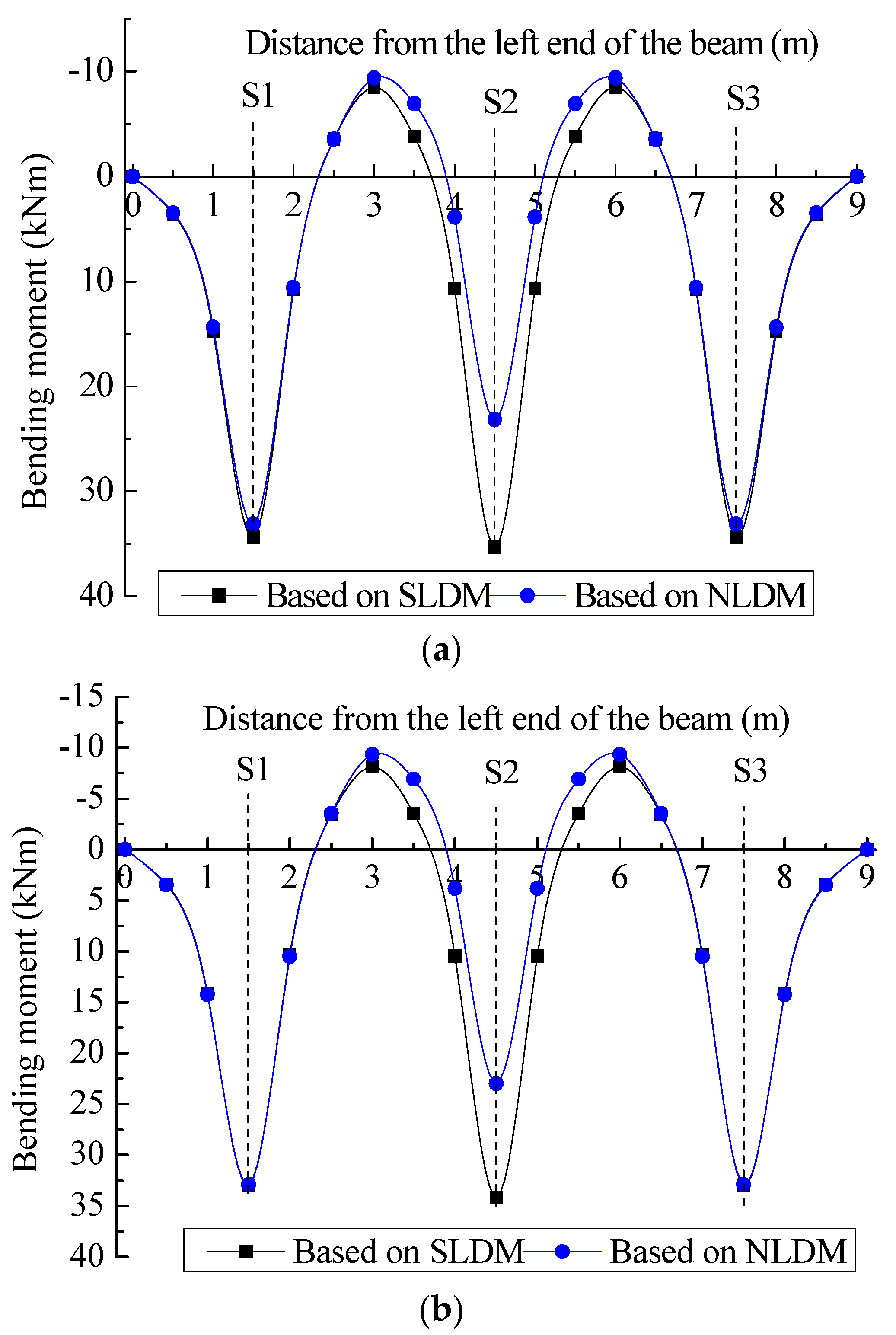
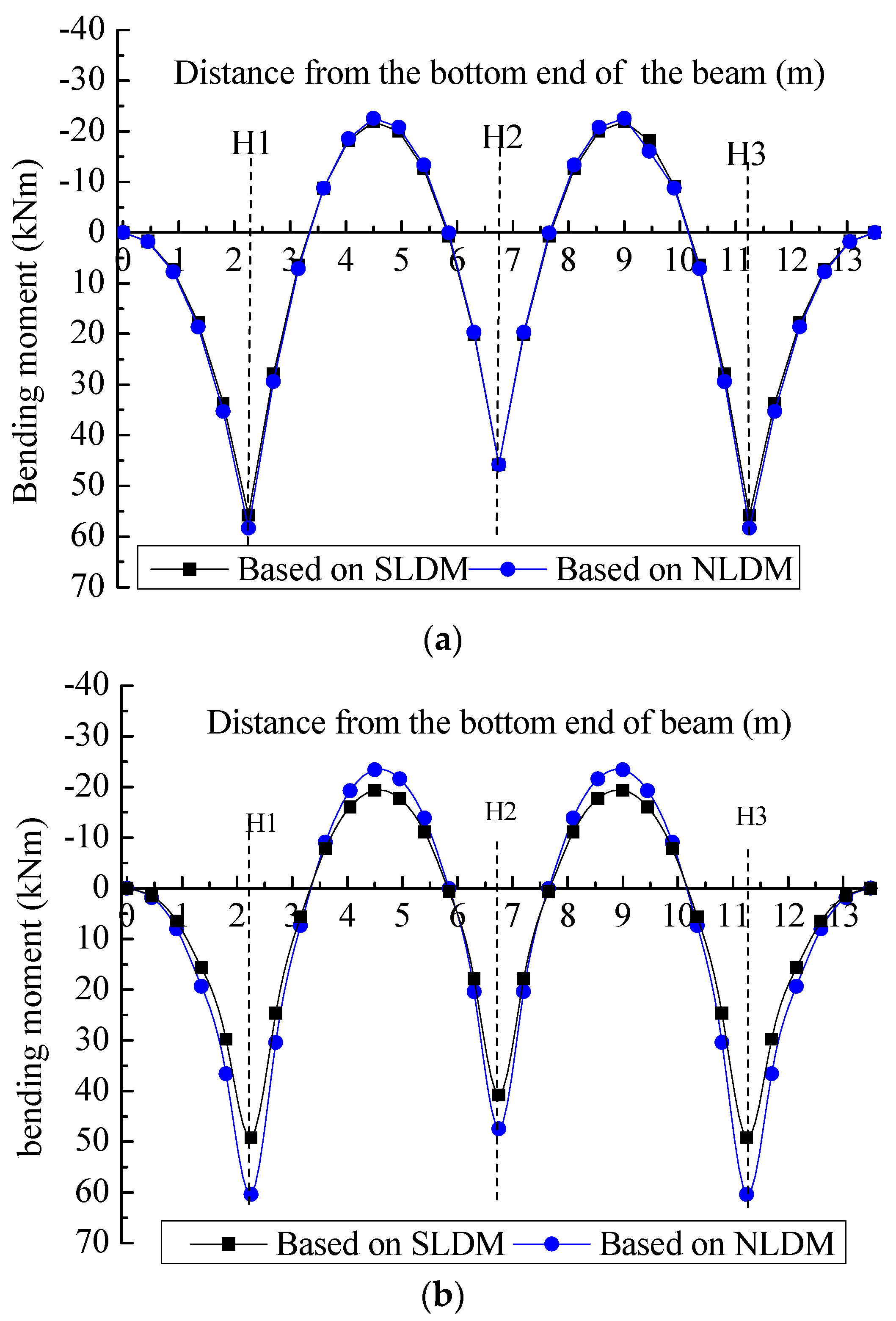
4.1.3. Bending Moment under the Design Condition

According to the known loads after the load distribution in Table 2 based on both load distribution methods, the lattice beam system was disassembled into six one-dimensional beams resting on the Winkler foundation, and the theoretical bending moments of the cross beams and vertical beams were calculated by the superposition method.
The theoretical bending moments of the cross beams H1 and H2 and the vertical beams S1 and S2 from the first lattice beam were calculated and the curves of the theoretical bending moments along the beam length were obtained.
The theoretical bending moments (Figure 11) based on both load distribution methods are in good agreement in the range of (0~3.0) m and (6.0~9.0) m of the cross beams H1 and H2, while the theoretical bending moments based on both load distribution methods are in poor agreement with each other in the range of (3.0~6.0) m. The differences of the maximum positive bending moments are as high as 12.15 kN∙m and 11.20 kN∙m at x = 4.5 m section of the cross beams H1 and H2, respectively. The above results can be interpreted as that the loads assigned by SLDM to the middle nodes (node 2, node 5) of the vertical beams are larger than those assigned to the nodes (nodes 1 and 3 of the cross beam H1, nodes 4 and 6 of the cross beam H2) of the cross beams, while the opposite is true for NLDM.
The theoretical bending moments (Figure 12a) of the vertical beam S1 based on both load distribution methods are well matched with each other along the beam length because the loads assigned to the vertical beam S1 based on both methods are almost the same. While the theoretical bending moments (Figure 12b) of the vertical beam S2 based on both load distribution methods are poorly matched with each other at the beam sections where the maximum bending moments (the maximum positive moment and the maximum negative moment) are located due to the larger and more uniform loads assigned to the vertical beams based on the NLDM, but the theoretical bending moments gradually match with each other far away from the beam sections where the maximum bending moments are located. The difference of the maximum positive bending moments is as high as 11.24 kN∙m at the section of x = 2.25 m of the cross beam S2.
The different distribution characteristics of the cross beams and the vertical beams on the theoretical bending moment are mainly due to the difference in both load distribution assumptions. Compared with SLDM, NLDM assigns the loads acting on the nodes to the cross beam with smaller and more uniform values, but to the vertical beam with larger and more uniform values due to the different spans of the beams running in different directions.

4.2. Results under the Actual Working Condition

4.2.1. Load Distributions under the Actual Working Condition

Influenced by the anchor slack and construction factors, after the anchor cable is tensioned and locked, the anchoring forces first decrease sharply, and then with the stress adjustment in soils after the slope reinforcement, the lattice beam anchoring system finally tends to be the actual working condition. Under the actual working condition, the average anchoring force of the anchor cables measured by the axial force sensor is 174 kN, and the component of the average anchoring force perpendicular to the slope surface is 173.64 kN. Based on both load distribution methods, the component of the average anchoring force perpendicular to the slope surface was assigned to the cross beams and the vertical beams, respectively, and the results are shown in Table 4.

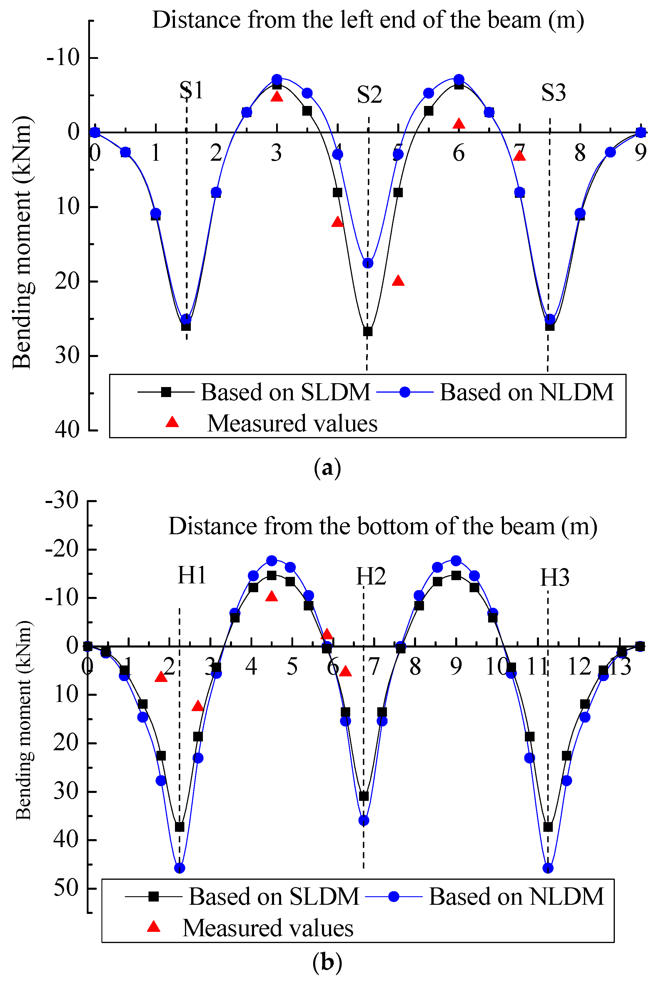
4.2.2. Bending Moment under the Actual Working Condition

According to the known loads after load distribution in Table 4 based on both load distribution methods, the theoretical bending moments of the beams resting on the Winkler foundation under the actual working condition were calculated. The comparisons of the results between the theoretical bending moments and the measured values under the actual working condition are shown in Figure 13 and Figure 14.
As can be seen from Figure 13 and Figure 14, the characteristics of the theoretical bending moments under the actual working condition are similar to those of the theoretical bending moments under the design condition. The theoretical bending moments based on both load distribution methods under the actual working condition are in relatively good agreement with the measured values at the key beam sections. Due to the inaccuracy of the modulus of subgrade reaction k and some errors in the testing process, although the measured values have a similar trend with the theoretical bending moments based on both load distribution methods, it is regrettable that the measured values of bending moments under the actual working condition cannot sufficiently prove the superiority of the new load distribution method.

5. Conclusion and Recommendations

Although it has various shortcomings, SLDM is widely used in China to analyze the internal force of lattice beams. In order to overcome the disadvantages of SLDM, an NLDM based on the force method was introduced in this paper. In order to verify the superiority of NLDM, both of the load distribution methods were used to perform the load distribution at the nodes for a lattice beam under the design and actual working conditions, and then, the theoretical bending moments of the lattice beam based on both load distribution methods were compared with each other and compared with the measured values. The following conclusions were drawn.
(1)
According to the static equilibrium condition and the deformation compatibility condition at the nodes of the lattice beam, the load distribution results under the design condition show that NLDM can distinguish the differences in stiffness of the beams in both directions relative to the ground, and evenly distribute the larger loads to the vertical beams with the larger spans, but evenly distribute the smaller loads to the cross beams with the smaller spans;
(2)
The deflections at the nodes of the lattice beam loaded with the known loads under the design condition are estimated separately, and the results of the deformation analysis show that the deflections of the cross beams and vertical beams are almost the same at the same nodes according to NLDM, thus demonstrating the superiority of the NLDM compared to the SLDM in terms of the deformation compatibility condition;
(3)
The results of the theoretical bending moment analysis based on the two load distribution methods show that the bending moments of the cross beam differ significantly in the middle third of the beam length, while the bending moments of the vertical beams differ significantly at the beam sections where the maximum bending moments are located;
(4)
Under the actual condition, the theoretical bending moments of the lattice beam based on both load distribution methods agree well with the measured values, but the measured values cannot sufficiently prove the superiority of NLDM due to the inaccuracy of the modulus of subgrade reaction k and the errors during the testing process;
(5)
Considering the fact that the deflections at the nodes are sensitive to the modulus of subgrade reaction k, based on NLDM, it is necessary to estimate the modulus of subgrade reaction k reasonably in order to obtain accurate results of the load distribution at the nodes and further accurate internal forces of the lattice beam.

Author Contributions

Methodology, J.F.; Formal analysis, J.F.; Investigation, S.Y.; Resources, B.S.; Data curation, B.S.; Writing—original draft, J.F.; Writing—review & editing, S.Y., B.D. and T.L.; Visualization, T.L.; Supervision, B.D. All authors have read and agreed to the published version of the manuscript.

Funding

This research was supported by the General project of the Hunan Provincial Education Department (Grant Numbers: 20C1608 and 21C0269), Research Foundation of the Department of Natural Resources of Hunan Province (Grant Number: 2023-44), Science Foundation for Youths of Hunan Province of China (Grant Number: 2021JJ40460), Hengyang Science and Technology Innovation Plan Project (Grant Number: 202250045321), which are gratefully acknowledged.

Data Availability Statement

The data used to support the findings of this study are available from the corresponding author upon reasonable request.

Conflicts of Interest

The authors declare that they have no conflict of interest to report regarding the present study.

Abbreviations

The following symbols are used in this paper:
Axthe first function of influence
Bxthe second function of influence
bxthe bottom width of the beam in the x direction
bythe bottom width of the beam in the y direction
Cxthe third function of influence
Dxthe forth function of influence
Eelastic modulus of the reinforced concrete
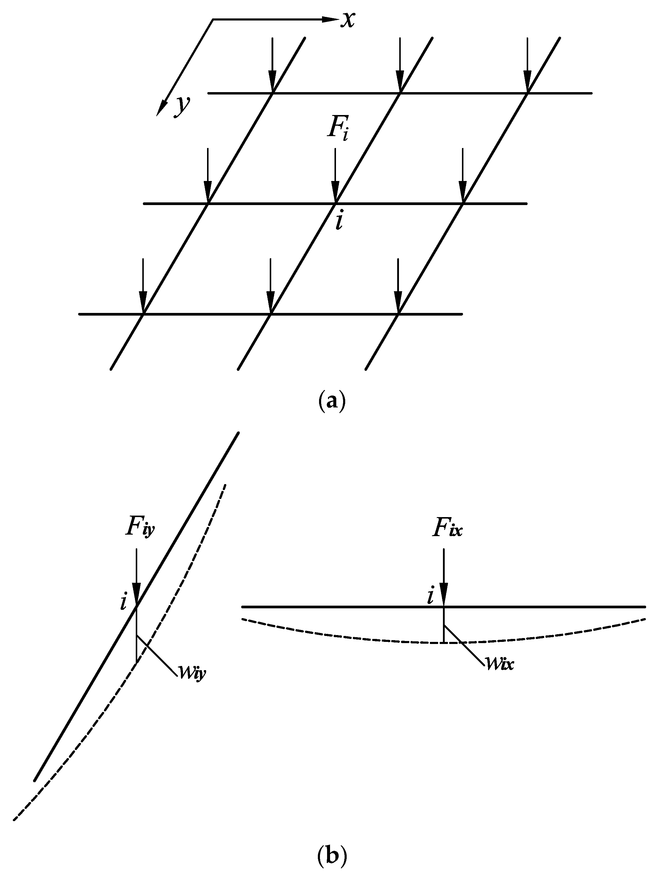
Fithe component of the total anchoring force perpendicular to the slope surface
Fixthe load assigned by Fi acting on the node i to the beam running in x direction
Fiyhe load assigned by Fi acting on the node i to the beam running in y direction
Imoment of inertia of the beam section
kmodulus of subgrade reaction
Pithe total anchoring force of the anchor cable acting on the node i of the lattice beam
Scharacteristic length of the beam on Winkler
Sxcharacteristic length of the beam in x direction
Sycharacteristic length of the beam in y direction
wixthe deflection of the beam in x direction at the node i
wiythe deflection of the beam in y direction at the node i
Zcomprehensive function of influence of the beam
Zxcomprehensive function of influence of the beam in x direction
Zycomprehensive function of influence of the beam in y direction
αthe angle of the design slope
δijdeflection at the node i caused by unit load at the node j of the beam on Winkler foundaton
θthe dip of the anchor cable to the horizontal plane

References

  1. Zhang, H.; Lu, Y.; Cheng, Q. Numerical simulation of reinforcement for rock slope with rock bolt (anchor cable) Frame Beam. J. Highw. Transp. Res. Dev. 2008, 3, 65–71. [Google Scholar] [CrossRef]
  2. Choi, K.; Cheung, R. Landslide disaster prevention and mitigation through works in Hong Kong. J. Rock Mech. Geotech. Eng. 2013, 5, 354–365. [Google Scholar] [CrossRef] [Green Version]
  3. Chen, Z.; Wang, Z.; Xi, H.; Yang, Z.; Zou, L.; Zhou, Z.; Zhou, C. Recent advances in high slope reinforcement in China: Case studies. J. Rock Mech. Geotech. Eng. 2016, 8, 775–788. [Google Scholar] [CrossRef]
  4. Deng, D.; Zhao, L.; Li, L. Limit-Equilibrium Analysis on Stability of a Reinforced Slope with a Grid Beam Anchored by Cables. Int. J. Geomech. 2017, 17, 06017013. [Google Scholar] [CrossRef]
  5. Shi, K.; Wu, X.; Liu, Z.; Dai, S. Coupled calculation model for anchoring force loss in a slope reinforced by a frame beam and anchor cables. Eng. Geol. 2019, 260, 105245. [Google Scholar] [CrossRef]
  6. Ye, S.; Fang, G.; Ma, X. Reliability Analysis of Grillage Flexible Slope Supporting Structure with Anchors Considering Fuzzy Transitional Interval and Fuzzy Randomness of Soil Parameters. Arab. J. Sci. Eng. 2019, 44, 8849–8857. [Google Scholar] [CrossRef]
  7. Zhang, J.J.; Niu, J.Y.; Fu, X.; Cao, L.C.; Yan, S.J. Failure modes of slope stabilized by frame beam with prestressed anchors. Eur. J. Environ. Civ. Eng. 2022, 26, 2120–2142. [Google Scholar] [CrossRef]
  8. Bao, X.; Liao, W.; Dong, Z.; Wang, S.; Tang, W. Development of Vegetation-Pervious Concrete in Grid Beam System for Soil Slope Protection. Materials 2017, 10, 96. [Google Scholar] [CrossRef]
  9. Zhu, X.; Chen, Z.; Ren, Y. The Application of Ecological Treatment Technology of Bolt and Lattice Beam in Highway Mountain Slope Support. Geotech. Geol. Eng. 2019, 37, 1891–1896. [Google Scholar] [CrossRef]
  10. Fan, J.; Yang, S.; Deng, B.; Sun, B.; Liu, T. A New Technique of Lattice Beam Construction with Pre-Anchoring for Strengthening Cut Slope: A Numerical Analysis of Temporary Stability during Excavation. Buildings 2022, 12, 1930. [Google Scholar] [CrossRef]
  11. Lin, Y.; Lu, L.; Yang, G. Seismic behavior of a single-form lattice anchoring structure and a combined retaining structure supporting soil slope: A comparison. Environ. Earth Sci. 2020, 79, 78. [Google Scholar] [CrossRef]
  12. Ai, X.; Sheng, M.; Su, X.; Ai, S.; Jiang, X.; Yang, S.; Huang, Z.; Ai, Y. Effects of frame beam on structural characteristics of artificial soil on railway cut-slopes in southwestern China. Land Degrad. Dev. 2021, 32, 482–493. [Google Scholar] [CrossRef]
  13. Huang, A.; Zhu, Y.; Wang, L.; Ye, S.; Fang, G. Three-Dimensional Stability of Unsaturated Soil Slopes Reinforced by Frame Beam Anchor Plates. Int. J. Geomech. 2023, 23, 04023068. [Google Scholar] [CrossRef]
  14. Luo, G.; Zhong, Y.; Yang, Y. Failure Mechanism and Mitigation Measures of the G1002 Electricity Pylon Landslide at the Jinping I Hydropower Station. Adv. Civ. Eng. 2020, 2020, 8820315. [Google Scholar] [CrossRef]
  15. Tao, H.-C.; Zhang, Y.; Dong, J.-X.; Zhou, Z.-Q.; Gong, X.-Y.; Zhang, S.-W. Study on Deformation Mechanism and Control Measures of Tanziyan Landslide. Geofluids 2022, 2022, 8237954. [Google Scholar] [CrossRef]
  16. Du, C.; Chen, J.; Chen, S.; Peng, M.; Shi, Z. Numerical analysis of a slope stabilized with piles and anchor cable frame beams. Environ. Earth Sci. 2023, 82, 100. [Google Scholar] [CrossRef]
  17. Lin, Y.-L.; Yang, G.-L.; Yang, X.; Zhao, L.-H.; Shen, Q.; Qiu, M.-M. Response of gravity retaining wall with anchoring frame beam supporting a steep rock slope subjected to earthquake loading. Soil Dyn. Earthq. Eng. 2017, 92, 633–649. [Google Scholar] [CrossRef]
  18. Lin, Y.-L.; Li, Y.-X.; Yang, G.-L.; Li, Y. Experimental and numerical study on the seismic behavior of anchoring frame beam supporting soil slope on rock mass. Soil Dyn. Earthq. Eng. 2017, 98, 12–23. [Google Scholar] [CrossRef]
  19. Lei, X.; Wang, B.; Li, N.; Hao, J. Study on Dynamic Response of Pressure Type Anchor and Lattice Beam System Under Seismic Loadings. Geotech. Geol. Eng. 2020, 38, 6057–6067. [Google Scholar] [CrossRef]
  20. Li, N.; Wang, B.; Yuan, L.; Men, Y.; Li, J.; Liu, X. Seismic response of soil slope reinforced by compression anchor and frame beam based on shaking table test. Arab. J. Geosci. 2020, 13, 261. [Google Scholar] [CrossRef]
  21. Maleki, M.; Nabizadeh, A. Seismic performance of deep excavation restrained by guardian truss structures system using quasi-static approach. Sn Appl. Sci. 2021, 3, 417. [Google Scholar] [CrossRef]
  22. Maleki, M.; Mohammad, H. Assessment of the Pseudo-static seismic behavior in the soil nail walls using numerical analysis. Innov. Infrastruct. Solut. 2022, 7, 262. [Google Scholar] [CrossRef]
  23. Maleki, M.; Khezri, A.; Nosrati, M.; Hosseini, S.M.M.M. Seismic amplification factor and dynamic response of soil-nailed walls. Model. Earth Syst. Environ. 2023, 9, 1181–1198. [Google Scholar] [CrossRef]
  24. Tang, H.; Xu, Y.; Cheng, X. Research on design theory of lattice frame anchor structure in landslide control engineering. Rock Soil Mech. 2014, 25, 1683–1687. (In Chinese) [Google Scholar] [CrossRef]
  25. Zhu, D.P.; Xu, Y.Z.; Yan, E.C.; Xiao, W. In-situ test and study of the internal force features of prestress anchor lattice beam. In Boundaries of Rock Mechanics; CRC Press: Boca Raton, FL, USA, 2008; pp. 609–614. [Google Scholar]
  26. GB/T 38509-2020; Code for the Design of Landslide Stabilization. China Geological Environmental Monitoring Institute, China Standard Press: Beijing, China, 2020. (In Chinese)
  27. Wu, X. Building Foundation; South China University of Technology Press: Guangzhou, China, 1997. (In Chinese) [Google Scholar]
  28. Li, Q.; Zhang, G.; Tang, H.; Wang, L. Analysis on internal force of lattice beam and optimization design. Coal Geol. Explor. 2006, 34, 50–53. (In Chinese) [Google Scholar]
  29. Chen, G.; Wang, J.; Lin, Z. Simplified calculation method of slope frame beam on winkler assumption and its engineering application. J. Geomech. 2016, 24, 822–827. (In Chinese) [Google Scholar] [CrossRef]
  30. Arthur, A.; Richard, J. Advanced Mechanics of Materials, 6th ed.; John Wiley & Sons, Inc.: Hoboken, NJ, USA, 2002. [Google Scholar]
  31. Hetenyi, M. Beams on Elastic Foundation; University of Michigan Press: Ann Arbor, MI, USA, 1946. [Google Scholar]
  32. Shen, J. Design Manual of Foundation; Shanghai Science and Technology Press: Shanghai, China, 1988. (In Chinese) [Google Scholar]
  33. Lin, T. Foundation Design; Huazhong University of Science and Technology: Wuhan, China, 1996. (In Chinese) [Google Scholar]
  34. Li, J.; Zhu, Y.; Ye, S.; Ma, X. Internal force analysis and field test of lattice beam based on Winkler theory for elastic foundation beam. Math. Probl. Eng. 2019, 2019, 5130654. [Google Scholar] [CrossRef]
  35. Dinev, D. Analytical solution of beam on elastic foundation by singularity functions. Eng. Mech. 2012, 19, 381–392. [Google Scholar] [CrossRef]
Figure 1. Several applications of lattice beams with tied-back anchor cables. (a) Lattice beams and molded concrete panel. (b) Lattice beam and cast-in-place concrete panel. (c) Lattice beam and shotcrete panel. (d) Lattice beam and plant protection.
Buildings 13 01731 g001
Figure 2. A case of structural damage of lattice beam.
Buildings 13 01731 g002
Figure 3. Mechanical model of lattice beam with tied back anchor cables.
Buildings 13 01731 g003
Figure 4. Mechanical model of SLDM: (a) lattice beam subjected to concentrated loads at the nodes; (b) the deformation analysis at a node.
Buildings 13 01731 g004
Figure 5. Mechanical model for the deflection of a semi-infinite beam with a concentrated load near its end.
Buildings 13 01731 g005
Figure 6. Mechanical model of the corner node.
Buildings 13 01731 g006
Figure 7. Mechanical model of the edge node.
Buildings 13 01731 g007
Figure 8. Mechanical model of the inner node.
Buildings 13 01731 g008
Figure 9. Mechanical model of NLDM: (a) lattice beam subjected to concentrated loads at the nodes; (b) the deformation analysis at node i.
Buildings 13 01731 g009
Figure 10. Plane dimensions of the lattice beam (mm).
Buildings 13 01731 g010
Figure 11. The theoretical bending moments of the cross beam under the design condition (a) the theoretical bending moment of H1; (b) the theoretical bending moment of H2.
Buildings 13 01731 g011
Figure 12. The theoretical bending moments of the vertical beams under the design condition (a) the theoretical bending moment of S1; (b) the theoretical bending moment of S2.
Buildings 13 01731 g012
Figure 13. Comparison of the measured values and the theoretical bending moment of the first lattice beam under the actual working condition (a) the theoretical bending moment of H1; (b) the theoretical bending moment of S2.
Buildings 13 01731 g013
Figure 14. Comparison of the measured values and the theoretical bending moment of the second lattice beam under the actual working condition (a) the theoretical bending moment of H2; (b) the theoretical bending moment of S2.
Buildings 13 01731 g014
Table 1. Parameters required for load distribution at the node.
Parameter TypeElastic Modulus of Reinforced Concrete
E (kPa)
Coefficient of Subgrade Reaction
k (kN/m3)
Values2.8 × 10712,000
Table 2. Results of the load distribution under the design condition.
Node TypeBased on SLDMBased on NLDM
Fix (kN)Fiy (kN)Fix (kN)Fiy (kN)
The corner nodes (1, 3, 7, 9)104.38125.1499.14130.38
The edge nodes (2, 8)119.02110.5094.44135.08
The edge nodes (4, 6)100.17129.3598.46131.06
The inner node (5)114.76114.7693.76135.76
Table 3. Comparison of deflections at the nodes under the design condition.
Node TypeBased on SLDMBased on NLDM
wix (m)wiy (m)wix (m)wiy (m)
The corner nodes (1, 3, 7, 9)0.01000850.008863050.009226440.00922611
The edge nodes (2, 8)0.01142900.007827350.009559230.00955864
The edge nodes (4, 6)0.01040040.009027710.009162670.00916265
The inner node (5)0.01130630.008007150.009491420.00949134
Table 4. Comparison results of load distribution under the actual working condition.
Node TypeBased on SLDMBased on NLDM
Fix (kN)Fiy (kN)Fix (kN)Fiy (kN)
The corner nodes (1, 3, 7, 9)78.9794.6775.0098.64
The edge nodes (2, 8)90.0483.6071.44102.20
The edge nodes (4, 6)75.7897.8674.4999.15
The inner node (5)86.8286.8270.93102.71
Disclaimer/Publisher’s Note: The statements, opinions and data contained in all publications are solely those of the individual author(s) and contributor(s) and not of MDPI and/or the editor(s). MDPI and/or the editor(s) disclaim responsibility for any injury to people or property resulting from any ideas, methods, instructions or products referred to in the content.

