Abstract
Single-column elevated station structures are irregular structures with long-span cantilever beams and individual pier columns in the transverse section. The uneven mass and stiffness in the horizontal and vertical planes necessitate research on the seismic performance of these structures. This study performed a nonlinear response-history analysis (NRHA) of a single-column elevated station structure using the finite element program MSC.MARC and analysed its seismic performance under different seismic intensities. The stress states of the primary components were evaluated, and the effect of vertical earthquake motion on the seismic performance of the structure was considered. The torsional behavior caused by the uneven mass and stiffness in both horizontal and vertical directions should be considered, and energy dissipation measures should be taken to reduce the internal force and deformation of the bottom-pier columns and second-floor columns in the process of designation to improve the seismic performance of the structure. A bidirectional pushover analysis (BPA) was applied. The load amplification factor was adjusted to optimize the BPA results. The results of the modified BPA were similar to those of the NRHA, indicating the computational reliability of the modified BPA. The modified BPA method was accurate, applicative, and efficient. The BPA can improve computational efficiency compared to NRHA and can be widely applied in the structural design process for practical engineering applications.
1. Introduction
A single-column elevated station structure is a structural system in which the upper viaduct bridge and station building are combined as an integrated structure. In this structure, a single-column pier is positioned longitudinally in the middle of the road at the bottom of the structure, and a long-span cantilever beam is placed laterally on both sides of the pier column as the transformer beam to transfer the load of the upper platform floor to the lower pier column [1]. Single-column elevated station structures have gained widespread attention in the continuous development of city construction because they can effectively improve space utilization and minimize the impact of the structures on ground traffic [2]. The single-column structure system with a long-span cantilever beam is primarily characterized by extreme irregularities in which the upper part of the structure is relatively larger than the lower part, and the length in the longitudinal direction of the structure is significantly longer than that in the transverse direction. This irregularity results in a substantial variation in the structure stiffness between the longitudinal and transverse orientations. This necessitates research on the seismic performance of the station.
Many studies have been conducted on single-column elevated station structures. Zhao [3] emphasized that several deficiencies in the response spectrum method cause the adverse effects of uneven mass and stiffness distribution to be underestimated when evaluating the seismic performance of a single-column elevated station. Liu [4] further investigated the stress state of a single-column pier and long-span cantilever beam in a system using a time-history analysis approach. The results demonstrated that in addition to the significant bending moment and shear force in the component design, the single-column pier and cantilever beam are subjected to a greater torsion effect when considering the accidental eccentric effect of the structure. To address the significant self-weight and low ductility of concrete structures and enhance their seismic performance, Xu et al. [5,6,7] introduced composite structure into the structural system to optimize primary components, such as the pier column and cantilever beam. The composite structure system can effectively reduce the component size and realize multiple failure mechanisms in the vertical and horizontal directions, improving the seismic performance of complex station systems. Zhuang et al. [8] applied multiple passive energy dissipation (MPED) devices to the vulnerable parts of the structure to improve its seismic performance. Nonlinear static and time-history analyses of the key substructure and entire structure revealed that the MPED system could effectively enhance the strength, stiffness, and ductility of the structure, reduce the general response significantly, and increase the energy dissipation capacity of the overall structure.
Researchers used nonlinear response-history analysis (NRHA) to analyze the structure’s response under intensive earthquakes. This method has comparable computational precision; however, the calculation process is relatively complex and time-consuming, making it challenging for engineering project applications [9,10]. By contrast, pushover analysis is a nonlinear static procedure used extensively to evaluate the seismic performance of a structure owing to its high computational efficiency [11,12]. This approach is typically used in structures with regular forms because it is typically available for structures vibrating largely in the fundamental mode [13,14]. Recent research expanded pushover analysis to high-rise buildings and two-way asymmetric structures [15,16]. Chopra [17] proposed an enhanced pushover analysis method based on the structural dynamics theory to consider the effects of higher vibration modes. Fajfar [18,19,20] extended the N2 method to plan-asymmetric buildings and applied a correction factor to the results of pushover analysis considering torsion effects. Lin and Tsai [21] developed an approximation approach for the earthquake resistance analysis of plane-asymmetric buildings with uneven mass or stiffness. The seismic performance under two-way ground motions can be accurately assessed using three degrees of freedom (3DOF) modal sticks. Cimellaro [22,23] proposed a bidirectional pushover analysis (BPA) method for evaluating the seismic performance of irregular buildings’ underground vibrations in two horizontal directions. The results of the proposed method were consistent with those of the time-history analysis. Moreover, the load amplification factors in the two horizontal directions were suggested and differed significantly from those of the European code. Ruggieri et al. [24] presented a procedure for low-complexity structural models to predict the global response of asymmetric-plan low-rise buildings. This procedure created an idealized 3D structure with a few degrees of freedom compared with a full-scale multi-degree-of-freedom structural model, and the proposed structure can match the inelastic response of a building. The simplified model can reduce the computational cost within the framework of performance-based earthquake engineering. To this goal, rules and equations are proposed for achieving equivalence among the linear and nonlinear properties of the building analysed and the related 3D reduced-order model. Ruggieri and Uva [25] presented a study of the adjustment of conventional pushover analysis in the latest release of the Italian Building Code. The new pushover analysis modified the load profile and the combination of the spatial effects. The results in terms of global and local performances are processed and critically analyzed. The differences between the traditional and modified approaches were researched, and effective improvements were proposed. Wang et al. [26] evaluated the seismic performance of a representative 35-story steel moment frame building. Nonlinear response history analysis, probabilistic checks, and immediate occupancy were performed based on the provisions, and the results predicted that the case study building failed to meet the recommended performance objectives and that possible retrofits were needed. Mouhine and Hilali [27,28,29] researched the seismic vulnerability of building structures with setback irregularity. The nonlinear pushover analysis was performed, and the results indicated that the setback seriously affected the structure’s performance. It is important to emphasize that the structural performance of mid-rise reinforced concrete buildings is significantly reduced when the vertical geometric irregularity passes from the bottom of the structure to the upper levels. Moreover, these results suggested the necessity of improving the constructive provisions recommended by the current design codes. The zones close to the setback where the stresses were generally concentrated should be reinforced to improve the ductility of the structural components to dissipate the energy brought by the earthquake while keeping the structural integrity of the constructions. Georgiou et al. [30] examined a historical concrete building with high irregularities in both plan and elevation. The irregularity in the plan and elevation of the whole structure caused great differences in the drift demand obtained from time history analysis and nonlinear static analysis; hence the inelastic static analysis based on the pushover curve of the structure must be adjusted accordingly to different load distributions. Das et al. [31] consulted a large amount of the literature and design provisions concerning buildings with asymmetry and irregularity, which became a major cause for collapses of structures during earthquakes. The limitations of the existing code provisions for this type of structure were pointed out, and indications about how the code provisions can be modified were given.
Although pushover analysis is typically performed on different types of structures, it has rarely been used for single-column elevated station structures. This study performed a nonlinear response-history analysis on a single-column elevated station structure to evaluate the seismic performance of the overall structure and its primary components. The mechanical characteristics and failure mechanism are discussed, and recommendations for improving earthquake resistance are provided. Moreover, a bidirectional pushover analysis was performed, and the results of the two methods were compared. The load amplification factor was adjusted based on the disparity between the two methods. Finally, the accuracy and efficiency of the modified BPA were evaluated to simplify the computation process under intensive earthquakes.
2. Investigated Structure
2.1. Building Description
The investigated structure was a single-column elevated station with a side-type platform, as shown in Figure 1. The length, width, and height of the station were 90 m, 23.6 m, and 16.7 m, respectively. In the transverse direction (the X direction), a cantilever beam with a clear span of 10.7 m was supported by a 2.2 m-wide pier column at the bottom. Seven pier columns were placed 15 m apart along the railway in the longitudinal direction (the Y direction). The structure had three floors in the vertical direction (the Z direction), with heights of 8.95 m, 4.45 m, and 3.3 m. Figure 1 shows the configuration of the primary components and load distribution of the structure.
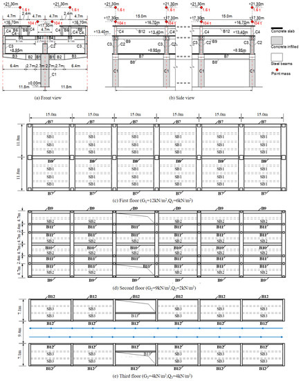
Figure 1.
Configuration of the primary components and load distribution of the structure. (a) Front view; (b) side view; (c) first floor; (d) second floor; (e) third floor.
Table 1 shows the section information of each component. Concrete-filled steel tube columns supported the first and second floors of the structure, and steel tube columns supported the third floor. The transverse cantilever beam comprised three sections (B1–B3). The B1 section was filled with concrete to enhance the bearing capacity, stiffness, and torsion resistance of the section. The B3 section used variable sections to lessen the self-weight of the cantilever beam and reserve more space for road traffic. The B4 segment on the second floor was also filled with concrete to bear the shear force and bending moment caused by the concentrated load of the railway track. In the longitudinal direction of the structure, the primary beams (B7–B12) were rigidly connected to the columns. The secondary beams (SB1–SB3) were hinged with the transverse beam. The thickness of the concrete slab was 150 mm. The internal two-way reinforcement was placed with a 14 mm diameter and 100 mm spacing. The composite action was developed between the concrete slab and steel beam to improve the stiffness of the components and the integrity of the structure.

Table 1.
Parameters of the primary components 1.
2.2. Performance Evaluation
According to the Code for Seismic Design of Buildings (CSDB) [32], the system and component levels are the two primary elements of the seismic performance assessment of the structure. The system level primarily evaluates the inter-storey drift ratio and top-floor displacement of the structure. The component level primarily considers the stress state of the members and the generation of plastic hinges. The evaluation index was normalized during the analysis to better assess the changes in various indicators under different earthquake intensities, allowing for a clearer comparison of the indicators at the system and component levels. Seismic fortification ensures that the structure can quickly restore to its previous state by repairing under fortification intensity and will not collapse when a rare earthquake occurs.
2.3. Numerical Modelling
A high-precision finite element simulation was performed based on the subroutine package COMPONA-MARC developed on MSC.MARC Version 2007rl [33,34]. This subroutine package combines the fiber section model and no-slip beam element with distributed plastic hinges to obtain a fiber beam element for the seismic performance analysis of steel-concrete composite structures [35,36]. The hysteretic law was improved to consider the strength degradation phenomenon during repeated unloading and reloading. The Bauschinger effect can be considered in the adopted steel and reinforcement material model. Therefore, this modified model can precisely simulate the complex nonlinear behavior of composite members under seismic action. It also has the advantages of numerical stability, high efficiency, broad applicability, and convenient preprocessing and post-processing. Table 2 shows the mechanical parameters of the materials in the model.
Table 2.
Mechanical parameters of the materials.
3. Numerical Analysis of the Structure
3.1. Nonlinear Response-History Analysis
3.1.1. Vibration Characteristics of the Structure
Table 3 lists the period and mass participation factor of the first six modes of the single-column elevated station. Figure 2 shows the shapes of the first three modes. The shapes of the first three modes are translation in the X direction, in-plane torsion, and translation in the Y direction. The torsional effect of the single-column elevated station structure is significant. The second mode shows a noteworthy torsion shape resulting from the irregularity of the structure in the plane and vertical direction, indicating that the vibration characteristics of the structures are influenced by higher mode vibrations under earthquake actions. In addition, the ratio of the first natural vibration period dominated by in-plane torsion to the first natural vibration period dominated by translation in the X and Y direction are 0.71 and 1.38, respectively. The latter is more than the limited value of 0.9 according to the provisions in Technical Specifications for the Concrete of Tall Buildings [37] in China. This indicates the torsional effect of the structure is significant due to the influence of vibration coupling, and the torsional stiffness should be enhanced by adjusting the layout of the lateral force-resistant components.
Table 3.
Vibration characteristics of the investigated structure.
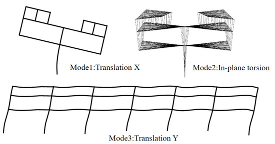
Figure 2.
Shapes of the first three modes.
3.1.2. Ground Motion Selection and Scaling
Ten earthquake accelerograms, including six natural and four artificial accelerograms, were selected for the dynamic nonlinear response-history analysis. The earthquake influence coefficient curve of each accelerogram was modified to match the earthquake influence coefficient curve adopted in the response spectrum method according to the CSDB requirements [38,39]. Figure 3 shows the selected accelerograms using the 8-degree rare earthquake as an example, with a damping ratio of 0.05. The black solid line and red dotted line represent the influence coefficient curve of the design spectrum and the average of the 10 influence coefficient curves, respectively. The two lines were similar, indicating that the selected accelerograms satisfied the CSDB requirements and ensured accurate and stable time-history results. Earthquake waves were applied in three directions simultaneously with a proportional coefficient of 1:0.85:0.65 in the Y, X, and Z directions during the time-history analysis. All earthquake waves had a predetermined duration of 30 s.
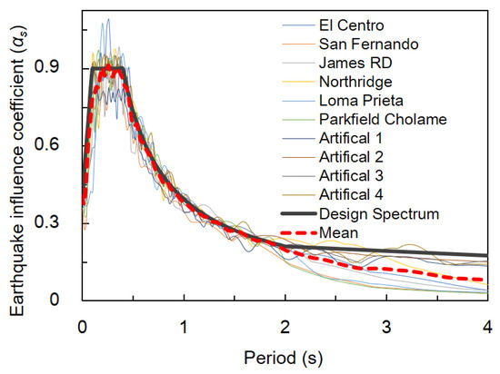
Figure 3.
Earthquake influence coefficient curves of design ground motions under 8-degree rare earthquake [peak ground acceleration (PGA) = 0.4 g].
3.2. Seismic Assessment of the Structure
3.2.1. Global Displacement and Inter-Storey Drift Ratio
Figure 4 shows the global displacement and inter-storey drift ratio under time-history analysis, including a limitation for the elastic-plastic inter-storey drift ratio given in the CSDB. As shown in the figure, the horizontal displacement in the two directions of the structure increased rapidly with increasing seismic intensity. The horizontal displacement also increased from the first floor to the third floor. However, the inter-storey drift ratio of the structure did not increase monotonously. In the X direction of the structure, the interstorey drift ratio decreased from the bottom to the top layer when the PGA increased to 0.6 g. The same phenomenon also occurred in the top layer of the structure at 0.2 g or 0.4 g PGA, contrasting sharply with the rapid monotonous increase of the inter-storey drift ratio in the Y direction and eventually exceeding the specified CSDB limits. This phenomenon indicates that the performance of the single-column elevated structure declines rapidly with an increase in the inter-storey drift ratio of the upper story when the seismic intensity increases. Moreover, the structure cannot satisfy the seismic fortification requirements under rare earthquakes.
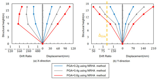
Figure 4.
Global displacement and inter-storey drift ratio at the center of floor mass.
The performance of the structure, particularly the upper story, deteriorated rapidly with an increase in seismic intensity, as illustrated in Figure 5. The proportion of the horizontal displacement was analyzed using Equation (1). Table 4 summarizes the composition of the drift ratio under different seismic intensities. The equation shows that the horizontal displacement comprises two parts: the residual displacement (denoted as ) and effective displacement (denoted as ), corresponding to the displacements caused by the rotation of the pier column and the shear deformation of the column, respectively. The latter is referred to as effective displacement because it causes damage to the primary structure.

Figure 5.
Inter-storey drift ratio composition.
Table 4.
Inter-storey drift ratio composition under different seismic intensities.
Table 4 indicates that when the structure experiences a severe earthquake, the effective displacement makes up less than 50% of the inter-storey drift ratio, indicating that the rotation of the pier column significantly affects the displacement of the upper story. Thus, the pier column deformation is key to controlling the inter-storey drift ratio of the structure and determines the direction for future seismic optimization.
3.2.2. Component Response
To evaluate the internal force at the ends of the columns and cantilever beams, the axial force, bending moment, shear force, and torque of the component were normalized using its ultimate bearing capacity, as shown in Equations (2)–(5). The bearing capacity of the component was calculated according to the provisions in the CSDB, and normalization made the internal force of the components more intuitive. It is worth mentioning that the bending moment at the end of the pier column was calculated in two ways: the index with and without considering the effects of the axial force, denoted by SFMN and SFM, respectively.
Table 5 shows the internal force of the pier column obtained through NRHA under different seismic intensities. The internal force was low, and the structure was in a fairly safe state at 0.2 g PGA. However, the internal force of the component developed rapidly, and the evaluation index SFM exceeded 1 as the PGA increased to 0.4 g or 0.6 g. The index considering the effect of axial force SFMN was lower than SFM, indicating that the axial force positively affected the capacity of the column. This was primarily because a relatively small axial force positively affected the bending capacity of the concrete-filled steel tubular column. This influence was less than 5%, indicating that the axial force had little impact on the index. The shear force and torque were significantly less than the axial force and bending moment of the column, indicating that the internal force of the pier column was dominated by compression and bending. However, SFV increased rapidly to 0.66 when PGA reached 0.6 g.
1 The terms Mx, My, Nc, Vx, Vy, T are the internal forces obtained from the NRHA or BPA. The terms Mu,x, Mu,y, Nu, Vu,x, Vu,y, Tu are the component bearing capacity calculated according to the provisions in Code for Seismic Design of Building.
Table 5.
Evaluation index of the single-column pier under compression and bending states.
Table 5.
Evaluation index of the single-column pier under compression and bending states.
| Index | SFM | SFMN | SFMN/SFM | SFV | SFT | |
|---|---|---|---|---|---|---|
| Seismic Intensity | ||||||
| 8-degree moderate earthquake (PGA = 0.2 g) | 0.75 | 0.71 | 0.95 | 0.28 | 0.05 | |
| 8-degree rare earthquake (PGA = 0.4 g) | 1.37 | 1.30 | 0.95 | 0.44 | 0.11 | |
| 9-degree rare earthquake (PGA = 0.6 g) | 1.46 | 1.42 | 0.97 | 0.66 | 0.16 | |
In addition to the pier column, the cantilever beam is significant for the load transfer mechanism of the structural system. This necessitates an evaluation of the internal force state of the cantilever beam. Table 6 shows the maximum bending moment and shear force of the cantilever beam obtained through the NRHA. The results were normalized by the ultimate bearing capacity. The results show that the increase in seismic intensity had little impact on the bending moment and shear force of the cantilever beam. When the seismic intensity increased from 0.2 g to 0.6 g, the bending moment and shear force increased by 15% and 10%, respectively, maintaining a lower stress state. This indicates that the bending and shear resistance of the cantilever beam sufficiently satisfied the demands of an intense earthquake.
Table 6.
Evaluation index of a cantilever beam under bending moment and shear force.
Table 7 compares the torsion moment at the end of the cantilever beam and pier column. The torsion moment of the cantilever beam was 1.5–1.7 greater than that of the pier column, making the impact of the torsion moment at the end of the cantilever beam non-negligible. Figure 6 shows the torsional mechanism at the end of the cantilever beam. Table 7 lists the torsion moment of these parts. The bending moment generated at the bottom of the column on the second floor was balanced by two parts: the torsion moment at the end of the cantilever beam and the bending moment at the end of beam B7. Under different seismic intensities, the torsion moment at the end of the cantilever beam was approximately 36% of the bending moment at the bottom of the middle column on the second floor. This indicates that the ratio of the torsion moment at the end of the cantilever beam to the bending moment at the bottom of the middle column on the second floor was relatively fixed. The torsion moment at the end of the cantilever beam can be reduced by reducing the bending moment at the bottom of the middle column.
Table 7.
Torsion moment of the pier column and cantilever beam.
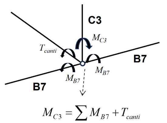
Figure 6.
Torsional mechanism of cantilever transfer beam.
The primary components of a single-column elevated station structure bear a large axial force and bending moment, and the shear force and torsion moment cannot be disregarded. Therefore, the stress states of the members in the combined states of compression, bending, shear, and torsion should be considered. The evaluation index of the primary components is given by Equation (6) according to Han Linhai’s research [40] on the bearing capacity of concrete-filled steel tube columns under a combined stress state. This index comprises compression-bending and shear-torsion parts and combines each internal force and its bearing capacity. Figure 7 summarizes the internal force of primary components under different seismic intensities. The value on the vertical coordinate axis represents the evaluation index of the component derived from Equation (6), and the abscissa axis indicates different components. The results show that among all the components, column C3 has the highest evaluation index, which makes it the most dangerous part of the structure. The evaluation indexes of the components increase rapidly with the increase of seismic intensity, especially columns C1 and C3; the evaluation index is greater than 1.0 at 0.4 g PGA. The evaluation index of the beams and columns on the third floor is relatively low, but the beams in the Y direction on the first and second floors B7–8 and B9–11 are at significant risk when PGA increases to 0.6 g. These high-risk areas should be considered in the design of energy dissipation.
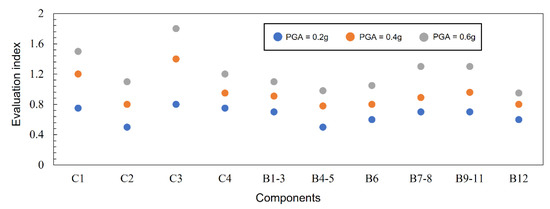
Figure 7.
Evaluation index and its proportion for each component.
3.2.3. Failure Mechanism and Seismic Performance
Figure 8 shows the distribution of the plastic hinge on the single-column elevated station structure at 0.4 g and 0.6 g PGA. The plastic hinge first appeared at the bottom of the pier column at t = 3 s at 0.4 g PGA and then developed at the bottom of the column on the second floor at t = 10 s. When t = 30 s, the plastic hinge was observed at the bottom of each column on the first and second floors and also occurred at the top of the column on the second floor. However, the plastic hinge was observed at the bottom of all the columns on the first floor and already developed to the end of the columns on the second floor at 0.6 g PGA. The plastic hinge extended to the top of the pier column and bottom of the columns on the third floor when t = 10 s and t = 30 s, respectively.
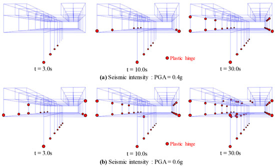
Figure 8.
Distribution of plastic hinge under different seismic intensities. (a) Distribution when PGA is 0.4 g. (b) Distribution when PGA is 0.6 g.
Table 8 shows the statistics on the number of plastic hinges at significant structure locations at 0.4 g and 0.6 g PGA. The plastic hinge only appeared in columns C1 and C3 at 0.4 g PGA. However, at 0.6 g PGA, the number of plastic hinges increased sharply in columns C1 and C3, and plastic hinges appeared in columns C2 and C4 and the structure beams. This indicates that the performance of the single-column elevated station structure degraded rapidly with an increase in the earthquake intensity owing to the irregularity of the structure, failing to meet the requirements of the performance-based seismic design. According to the horizontal displacement and inter-storey drift ratio of each floor shown in Figure 4, the top floor had the largest inter-storey drift ratio; however, the number of plastic hinges was relatively small. Plastic hinges were primarily concentrated on columns C1 and C3, indicating that the damage to the structure was primarily concentrated in the first two layers. This was consistent with the conclusions in Section 3.2.1 that the rotation of the bottom-pier column was primarily responsible for the horizontal displacement of the top floor, and controlling the deformation of the bottom-pier column can effectively improve the performance of structures under severe earthquakes.
Table 8.
Number of plastic hinges at key parts of the structure.
3.2.4. Overall Evaluation
The evaluation index indicates that the structure satisfied the criteria for earthquake fortification at 0.2 g PGA; however, the damage to the structure accumulated as the PGA increased to 0.4 g. A large proportion of the damage was concentrated at the bottom of the pier column, making it impossible to immediately meet the requirements of normal operating conditions. In addition, other structure indicators were close to the limits without redundancy; therefore, the structure did not meet the performance criteria at 0.4 g PGA. The damage to the structure increased severely at 0.6 g, and various indicators indicate that the structural performance was insufficient to prevent the collapse of the structure. Further investigation revealed that strengthening the seismic performance of the bottom column and effectively controlling the torsional effect of the structure are keys to enhancing the structural performance.
3.3. Influence of Vertical Earthquake Motion
Figure 9 and Figure 10 show the influence of vertical earthquake motion on the top floor displacement and base shear under NRHA in different seismic intensities. The value of the vertical acceleration was considered according to the CSDB. According to the results of NRHA, the top floor displacement and base shear in the X and Y direction were relatively consistent whether or not the vertical earthquake motion was considered, indicating that the vertical earthquake motion had little effect on the lateral performance of the structure. Table 9 summarizes the value of the top floor displacement and base shear in the NRHA. The results with and without vertical earthquake motion were recorded as W.EZ and WO.EZ, respectively. The average ratio of the top floor displacement between WO.EZ and W.EZ was 1.04, and the average ratio of the base shear between WO.EZ and W.EZ was 1.03 under different seismic intensities. The results suggest that the vertical earthquake motion was advantageous to the mechanical performance of the structure as the top floor displacement and base shear in W.EZ were slightly lower than that in WO.EZ. This was because the bearing capacity of the concrete-filled steel tubular columns improved when the axial force in the column was relatively low. However, the ratio R.EZ increased by less than 10% under the influence of vertical earthquake motion, demonstrating that the influence of vertical earthquake motion on the NRHA results was minimal.
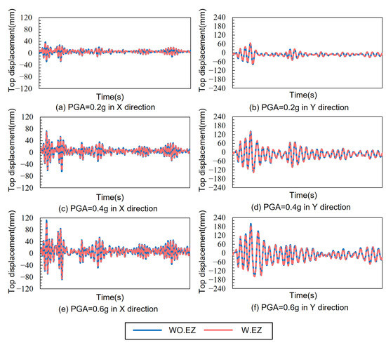
Figure 9.
Influence of vertical earthquake motion on the top floor displacement.
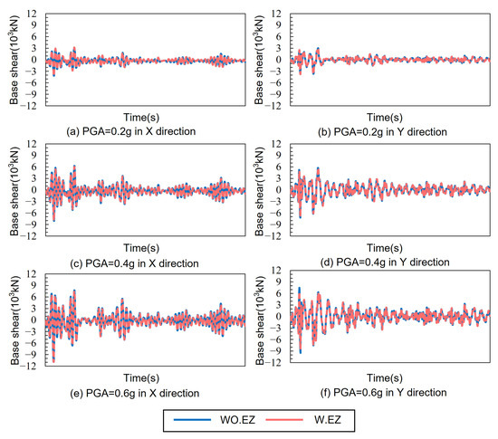
Figure 10.
Influence of vertical earthquake motion on the base shear.
Table 9.
Effect of vertical earthquake motion on the top floor displacement and base shear.
The cantilever beam is an essential component of the single-column elevated structure because it bears the load of the upper structure and transfers it to the pier column. Vertical seismic action significantly affects the cantilever component; therefore, in addition to the influence on the global displacement and base shear, the influence of vertical earthquake motion on the cantilever beam should also be considered. Table 10 shows the impact of vertical earthquake motion on the cantilever beam under NRHA, including the vertical deformation at the free end of the beam and maximum shear force at the root. The results show that the impact of vertical earthquake motion on components sensitive to vertical earthquake motion, such as cantilever beams, was relatively small. The impact of vertical earthquake motion on the cantilever beam was less than 15%, and horizontal earthquake motion controlled the component’s performance. Therefore, the effect of vertical earthquake motion on the structure can be neglected in the following discussion.
Table 10.
Effect of vertical earthquake motion on the cantilever beam.
4. Nonlinear Static Analysis
4.1. Bidirectional Pushover Analysis
NRHA can accurately determine the structure’s response under intensive earthquakes; however, the procedure is sophisticated and time-consuming. Thus, applying this method to practical engineering is unreasonable. The pushover analysis is a nonlinear static analysis method based on the structural response spectrum. This method has significant advantages over NRHA in computational efficiency. Pushover analysis in both the X- and Y-directions was performed using the finite element analysis program MSC.MARC to verify the accuracy of this method. The analysis was performed according to the instructions of the ATC-40 [41]. The capacity spectrum was obtained by applying an inverted triangular lateral load to the structure, represented by the black line in Figure 11. Design response spectra obtained from CSDB for the 8-degree moderate earthquake (PGA = 0.2 g, = 0.05), 8-degree rare earthquake (PGA = 0.4 g, = 0.09), and 9-degree rare earthquake (PGA = 0.6 g, = 0.14) were converted into demand spectra and drawn in the same figure with the capacity spectrum. The horizontal displacement of the structure can be obtained according to the intersection point of the capacity and demand spectra, and the structural performance of a single-column elevated station can be evaluated.
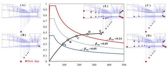
Figure 11.
Bidirectional pushover analysis (BPA) results of the structure. (A) First appearance of plastic hinge. (B) Appearance of plastic hinge on the bottom of the columns on the second floor. (C) Appearance of plastic hinge on the top of the columns on the second floor. (D) Appearance of plastic hinge at the root of cantilever beam. (E) Appearance of plastic hinge on the bottom of the columns on the third floor.
Figure 11 shows the appearance of the plastic hinge at different stages of the pushover analysis. A plastic hinge was first observed at point A, located at the base of the pier column on the first floor, indicating no plastic hinge in the structure at 0.2 g PGA. A plastic hinge appeared at the bottom of the columns on the first and second floors at point B and extended to the top of the columns on the second floor at point C. The single-column elevated station under the 8-degree intensity rare earthquake was in the state between points B and C. Plastic hinge also appeared at the root of the cantilever beam at point D, indicating that the structure had plastic hinges on the primary components on the first and second floors under the 9-degree intensity rare earthquakes; however, the components on the third floor had no plastic hinge. This phenomenon indicates that the pushover analysis had a certain deficiency in that it neglected the plastic hinge in some components compared with the results of the NRHA.
4.2. Global Response
Figure 12 shows the global displacement and inter-storey drift ratio of the structure under different seismic intensities obtained from the BPA of the single-column elevated station compared with the NRHA results. In the Y direction, the global displacement obtained from the BPA was slightly lower than that from the NRHA. However, the BPA and NRHA results were relatively close, with an average difference of less than 10%, indicating that the BPA was accurate in the Y direction. However, a considerable difference between the two methods was observed in the X direction. The BPA results were significantly less than the NRHA results, with an average difference of 30% at 0.4 g or 0.6 g PGA. The relative error increased from the bottom to the top floor. For example, the error was less than 1% on the first floor at 0.2 g PGA and increased sharply to 25% on the third floor. It can be concluded that the BPA and NRHA methods were consistent in the Y direction. By contrast, a significant discrepancy was observed in the X direction and required further adjustment on the BPA method.
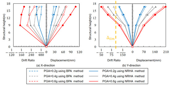
Figure 12.
Global displacement and inter-storey drift ratio at the center of floor mass derived from BPA and NRHA. (a) Results in X direction. (b) Results in Y direction.
4.3. Load Amplification Factor Adjustment
According to Lopez et al. [42,43], the load amplification factor should be considered in the two horizontal directions in the BPA, where should satisfy the condition . The value of the load amplification factor is key to the BPA because the analysis uses the multicomponent combination method to evaluate the structural response induced by the earthquake in the two horizontal directions. An index based on the study by Cimellaro et al. [22] was proposed to assess the difference between the BPA and NRHA under different values of the load amplification factor , as shown in Equation (7). This equation considers the difference between the results derived from the NRHA and BPA methods with a load amplification factor recorded as , , and . The three sub-indices were averaged to obtain the index of the overall structure. The sub-index of the translation in the X direction, , can be calculated using Equation (8), where Xi,BPA/NRHA denotes the displacement in the X direction at the mass center of the ith floor of the structure using the BPA or NRHA method. Similarly, the sub-index of the translation in the Y direction, , can be calculated using Equation (9). The sub-index of the rotation of the structure, , can be calculated using Equation (10), where i,BPA/NRHA denotes the maximum displacement at the edge of the ith floor of the structure using the BPA or NRHA method. The load amplification factor was adjusted in different models. When the index reaches its minimum value, the overall difference between the pushover analysis and time-history analysis in the displacement of each floor reaches its minimum value. In this case, the load amplification factor can be considered the optimal load amplification factor opt, indicating that the pushover analysis results reached the optimal value. Figure 13 shows that the optimal load amplification factor increased with increased seismic intensity. The optimal load amplification factors were 0.72, 0.82, and 0.84 at 0.2 g, 0.4 g, and 0.6 g PGA, respectively. These results were significantly larger than the recommended value of 0.3 for conventional structures in the specification. However, the values were closer to the recommended value of 0.6 by previous research, which performed a BPA on irregular structures. Figure 13 shows the distributions of the three sub-indices , , and . This indicates that made up the majority of the evaluation index, with an average proportion of over 50%. By contrast, and made up a considerably smaller and more evenly distributed portion. This indicates that the BPA and NRHA results differed significantly in the X direction of the structure, consistent with the results of the two methods in the X direction shown in Figure 12.
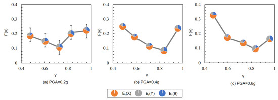
Figure 13.
Distribution of with the variance of under different seismic intensities.
Figure 14 compares the BPA and NRHA results when the load amplification factor value was set to the recommended value of 0.3 [44] and the optimal value opt. The deformation obtained from the BPA was lower than that from the NRHA at 0.2 g, 0.4 g, and 0.6 g PGA. The deformation obtained from the modified BPA increased and was closer to the NRHA results when the load amplification factor increased from 0.3 to opt. This indicates that the modified BPA can accurately reflect the general displacement of a highly irregular structure under bidirectional ground motion. This study suggests a new recommended value of the load amplification factor for two-way bidirectional analysis of highly irregular structures, as shown in Table 11.
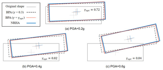
Figure 14.
Deformation of the structure under BPA and NRHA.
Table 11.
Recommended load amplification factor under different seismic intensities.
5. Conclusions
A single-column elevated station structure was analysed through NRHA and BPA to evaluate the seismic performance of highly irregular structures. The conclusions of this study are as follows:
- A composite structure was applied to reduce the component size and realize multiple failure mechanisms in a complex station system. A high-precision finite element simulation was performed based on MSC MARC. NRHA and BPA were performed at 0.2 g, 0.4 g, and 0.6 g PGA. The global displacement, component response, and failure mechanism were analyzed, and the results of the two methods were compared. The effect of vertical earthquake motion was calculated, but the results indicated that it could be neglected;
- The results of NRHA indicated that the single-column elevated station structure satisfied the requirements for earthquake fortification at 0.2 g PGA. However, damage accumulated as the intensity increased, making the structural performance, such as global displacement and internal force of the component, insufficient to meet the performance standards. In terms of the extreme irregularity of the structure, the second mode of the structure showed a noteworthy torsion shape. The torsional behavior caused by the uneven mass and stiffness in both horizontal and vertical directions should be considered in the structural design process. The torsion effect mainly affected the pier column and the cantilever beam, which are in a combined stress state of compression, bending, shear, and torsion. The results indicated that the deformation of the pier column is an important reason for the excessive deformation of the global displacement, and the torsion of the cantilever beam is closely related to the moment of the column on the second floor. Therefore, energy dissipation measures should be taken to reduce the internal force and deformation of the bottom-pier columns and second-floor columns in the process of designation to improve the seismic performance of the structure;
- Nonlinear static analysis was compared with NRHA, and the results of the two methods were consistent in the Y direction. By contrast, a significant variance was observed in the X direction. To eliminate the difference in the transverse direction, the load amplification factor was optimized, and the modified BPA method was proposed. The load amplification factors under different seismic intensities were recommended. The modified BPA is accurate and efficient, making this calculation method significant for practical engineering applications.
Author Contributions
Conceptualization, L.-D.Z.; methodology, Y.-F.L.; validation, Z.-H.W. All authors have read and agreed to the published version of the manuscript.
Funding
This research was funded by the National Natural Science Foundation of China (No. 52208177) and China Postdoctoral Science Foundation (No. 2022T150369).
Data Availability Statement
Some or all data, models, or codes that support the findings of this study are available from the corresponding author upon reasonable request.
Conflicts of Interest
The authors declare no conflict of interest.
References
- Shi, Z.Y.; Huang, X.; Li, X.Y. Structure design of single-column and long cantilever elevated station. Build. Sci. 2018, 34, 130–134. (In Chinese) [Google Scholar] [CrossRef]
- Wei, K.; Xu, Y.Z.; Li, M.T. Study on seismic performance of transverse frame of prefabricated elevated subway station. Structures 2022, 42, 255–267. [Google Scholar] [CrossRef]
- Zhao, J.L. Discussion on the seismic safety of single-column and long cantilever elevated station. Build. Struct. 2012, 42, 79–83. (In Chinese) [Google Scholar]
- Liu, B. Seismic Analysis and Suggestions of Single Pillar and Long Cantilever Elevated Station. Ph.D. Thesis, Chongqing University, Chongquing, China, 2016. [Google Scholar]
- Xu, L.Y.; Nie, J.G.; Ding, R.; Ma, G.; Wang, Y. Design and analysis on composite structural system of single-column elevated station. J. Build. Struct. 2015, 36 (Suppl. S1), 34–41. (In Chinese) [Google Scholar] [CrossRef]
- Xu, L.Y.; Nie, X.; Zhuang, L.D.; Tao, M.X. Seismic performance of composite single-column elevated station with hybrid energy dissipation technique. J. Build. Struct. 2019, 40, 50–62. (In Chinese) [Google Scholar]
- Xu, L.Y.; Nie, X.; Zhuang, L.D. Seismic performance of composite inverted pendulum light railway station. In Proceedings of the IABSE Symposium: Tomorrow’s Megastructures, Nantes, France, 19–21 September 2018; p. S23. [Google Scholar]
- Zhuang, L.D.; Nie, X.; Xu, L.Y. Seismic behavior of highly irregular structures with multiple passive energy dissipation system: Case study of a single-column elevated station. Struct. Des. Tall Spec. Build. 2020, 29, 1713. [Google Scholar] [CrossRef]
- Intekhab, M.S.; Das, S.; Jajnery, M.A.; Akhtar, S.; Sahoo, D.; Saha, P. Analysis Methods of Irregular High-Rise Buildings Subjected to Seismic Loads. J. Vib. Eng. Technol. 2022, 1, 1359–1382. [Google Scholar] [CrossRef]
- Varga, S.; Chiorean, C.G. Refined NSA approach for seismic assessment of regular RC frames. Gradevinar 2017, 69, 1137–1151. [Google Scholar] [CrossRef]
- Fajfar, P. Capacity spectrum method based on inelastic demand spectra. Earthq. Eng. Struct. Dyn. 1999, 28, 979–993. [Google Scholar] [CrossRef]
- Fajfar, P.; Gaspersic, P. The N2 method for the seismic damage analysis of RC buildings. Earthq. Eng. Struct. Dyn. 1996, 25, 31–46. [Google Scholar] [CrossRef]
- Kilar, V.; Fajfar, P. Simple pushover analysis of asymmetric buildings. Earthq. Eng. Struct. Dyn. 1998, 26, 233–249. [Google Scholar] [CrossRef]
- De Stefano, M.; Pintucchi, B. A review of research on seismic behaviour of irregular building structures since 2002. Bull. Earthq. Eng. 2008, 6, 285–308. [Google Scholar] [CrossRef]
- Bhatt, C.; Bento, R. Extension of the CSM-FEMA440 to plan-asymmetric real building structures. Earthq. Eng. Struct. Dyn. 2011, 40, 1263–1282. [Google Scholar] [CrossRef]
- Fajfar, P.; Marusic, D.; Perus, I. Torsional effects in the pushover-based seismic analysis of buildings. J. Earthq. Eng. 2005, 9, 831–854. [Google Scholar] [CrossRef]
- Chopra, A.K.; Goel, R.K. A modal pushover analysis procedure to estimate seismic demands for asymmetric-plan buildings. Earthq. Eng. Struct. Dyn. 2004, 33, 903–927. [Google Scholar] [CrossRef]
- Dolesk, M.; Fajfar, P. Simplified probabilistic seismic performance assessment of plan-asymmetric building. Earthq. Eng. Struct. Dyn. 2007, 36, 2021–2041. [Google Scholar] [CrossRef]
- Kreslin, M.; Fajfar, P. Seismic evaluation of an existing complex RC building. Bull. Earthq. Eng. 2010, 8, 363–385. [Google Scholar] [CrossRef]
- Kreslin, M.; Fajfar, P. The extended N2 method taking into account higher mode effects in elevation. Earthq. Eng. Struct. Dyn. 2011, 40, 1571–1589. [Google Scholar] [CrossRef]
- Lin, J.L.; Tsai, K.C. Seismic analysis of two-way asymmetric building systems under bi-directional seismic ground motions. Earthq. Eng. Struct. Dyn. 2008, 37, 305–328. [Google Scholar] [CrossRef]
- Cimellaro, G.P.; Giovine, T.; Lopez-Garcia, D. Bidirectional Pushover Analysis of Irregular Structures. J. Struct. Eng. 2014, 140, 04014059. [Google Scholar] [CrossRef]
- Cimellaro, G.P. Correlation in spectral accelerations for earthquakes in Europe. Earthq. Eng. Struct. 2013, 42, 623–633. [Google Scholar] [CrossRef]
- Ruggieri, S.; Chatzidaki, A.; Vamvatsikos, D.; Uva, G. Reduced-order models for the seismic assessment of plan-irregular low-rise frame buildings. Earthq. Eng. Struct. Dyn. 2022, 51, 3327–3346. [Google Scholar] [CrossRef]
- Ruggieri, S.; Uva, G. Accounting for the Spatial Variability of Seismic Motion in the Pushover Analysis of Regular and Irregular RC Buildings in the New Italian Building Code. Buildings 2020, 10, 177. [Google Scholar] [CrossRef]
- Wang, S.S.; Lai, J.W.; Schoettler, M.J.; Mahin, S.A. Seismic assessment of existing tall buildings: A case study of a 35-story steel building with pre-northridge connection. Eng. Struct. 2017, 141, 624–633. [Google Scholar] [CrossRef]
- Mouhine, M.; Halali, E. Seismic vulnerability for irregular reinforced concrete buildings with consideration of site effects. Mater. Today Proc. 2022, 58, 1039–1043. [Google Scholar] [CrossRef]
- Mouhine, M.; Hilali, E. Effect of setback irregularity location on the performance of RC building frames under seismic excitation. Arch. Civ. Eng. 2020, 66, 399–412. [Google Scholar] [CrossRef]
- Mouhine, M.; Hilali, E. Seismic vulnerability assessment of RC buildings with setback irregularity. Ain. Shams Eng. J. 2022, 13, 101486. [Google Scholar] [CrossRef]
- Georgiou, A.; Kotakis, S.; Loukidis, D.; Loannou, L. Case Study of Seismic Assessment of a Short Irregular Historic Reinforced Concrete Structure: Time-History Vs. Pushover Nonlinear Methods. J. Earthqu. Eng. 2023, 2023, 2193652. [Google Scholar] [CrossRef]
- Das, P.K.; Dutta, S.C.; Datta, T.K. Seismic Behavior of Plan and Vertically Irregular Structures State of Art and Future Challenges. Nat. Hazards Rev. 2021, 22, 04020062. [Google Scholar] [CrossRef]
- GB 50011-2010; Code for seismic design of buildings. China Architecture and Building Press: Beijing, China, 2010.
- Nie, J.G.; Tao, M.X. Theory of seismic response analysis of steel-concrete composite structures using fiber beam elements. J. Build. Struct. 2011, 32, 1–10. (In Chinese) [Google Scholar]
- Nie, J.G.; Tao, M.X. Application of seismic response analysis of steel-concrete composite structures using fiber beam elements. J. Build. Struct. 2011, 32, 11–20. (In Chinese) [Google Scholar]
- Tao, M.X.; Nie, J.G. Fiber Beam-Column Model Considering Slab Spatial Composite Effect for Non-linear Analysis of Composite Frame Systems. J. Struct. Eng. 2014, 140, 04013039. [Google Scholar] [CrossRef]
- Xu, L.Y.; Nie, X.; Tao, M.X. Rational modeling for cracking behavior of RC slabs in composite beams subjected to a hogging moment. Constr. Build. Mater. 2018, 192, 357–365. [Google Scholar] [CrossRef]
- JGJ 3-2010; Technical Specification for Concrete of Tall Building. China Architecture and Building Press: Beijing, China, 2010.
- Baker, J.W.; Lin, T.; Shahi, S.K.; Jayaram, N. New Ground Motion Selection Procedures and Selected Motions for the PEER Transportation Research Program 2011; PEER Report No. 2011-03; Pacific Earthquake Engineering Research Center, University of California: Berkeley, CA, USA, 2011. [Google Scholar]
- Jayaram, N.; Lin, T.; Baker, J.W. A computationally efficient ground-motionselection algorithm for matching a target response spectrum mean and variance. Earthq. Spectra 2011, 27, 797–815. [Google Scholar] [CrossRef]
- Ye, Y.; Han, L.H.; Tao, Z.; Guo, S.L. Experimental behaviour of concrete-filled steel tubular members under lateral shear loads. J. Constr. Steel Res. 2016, 122, 226–237. [Google Scholar] [CrossRef]
- Applied Technology Council. Seismic Evaluation and Retrofit of Concrete Buildings (ATC-40); California Seismic Safety Commission: West Sacramento, CA, USA, 1996.
- Lopez, O.A.; Chopra, A.K.; Hernandez, J.J. Evaluation of combination rules for maximum response calculation in multicomponent seismic analysis. Earthq. Eng. Struct. Dyn. 2001, 30, 1379–1398. [Google Scholar] [CrossRef]
- Lopez, O.A.; Hernández, J.J.; Bonilla, R.; Fernández, A. Response spectra for multicomponent structural analysis. Earthq. Spectra 2006, 22, 85–113. [Google Scholar] [CrossRef]
- CEN (European Committee for Standardization). Design of Structures for Earthquake Resistance, Part 1: General Rules, Seismic Actions and Rules for Buildings, Eurocode 8; CEN: Brussels, Belgium, 2004. [Google Scholar]


Disclaimer/Publisher’s Note: The statements, opinions and data contained in all publications are solely those of the individual author(s) and contributor(s) and not of MDPI and/or the editor(s). MDPI and/or the editor(s) disclaim responsibility for any injury to people or property resulting from any ideas, methods, instructions or products referred to in the content. |
© 2023 by the authors. Licensee MDPI, Basel, Switzerland. This article is an open access article distributed under the terms and conditions of the Creative Commons Attribution (CC BY) license (https://creativecommons.org/licenses/by/4.0/).