
LOD of a Computational Numerical Model for Evaluating the Mechanical Safety of Steel Structures


Abstract
:1. Introduction
1.1. Review of Works Addressing the Research Problem
1.2. Purpose and Objectives of the Research Addressed in this Article—Scientific Novelty
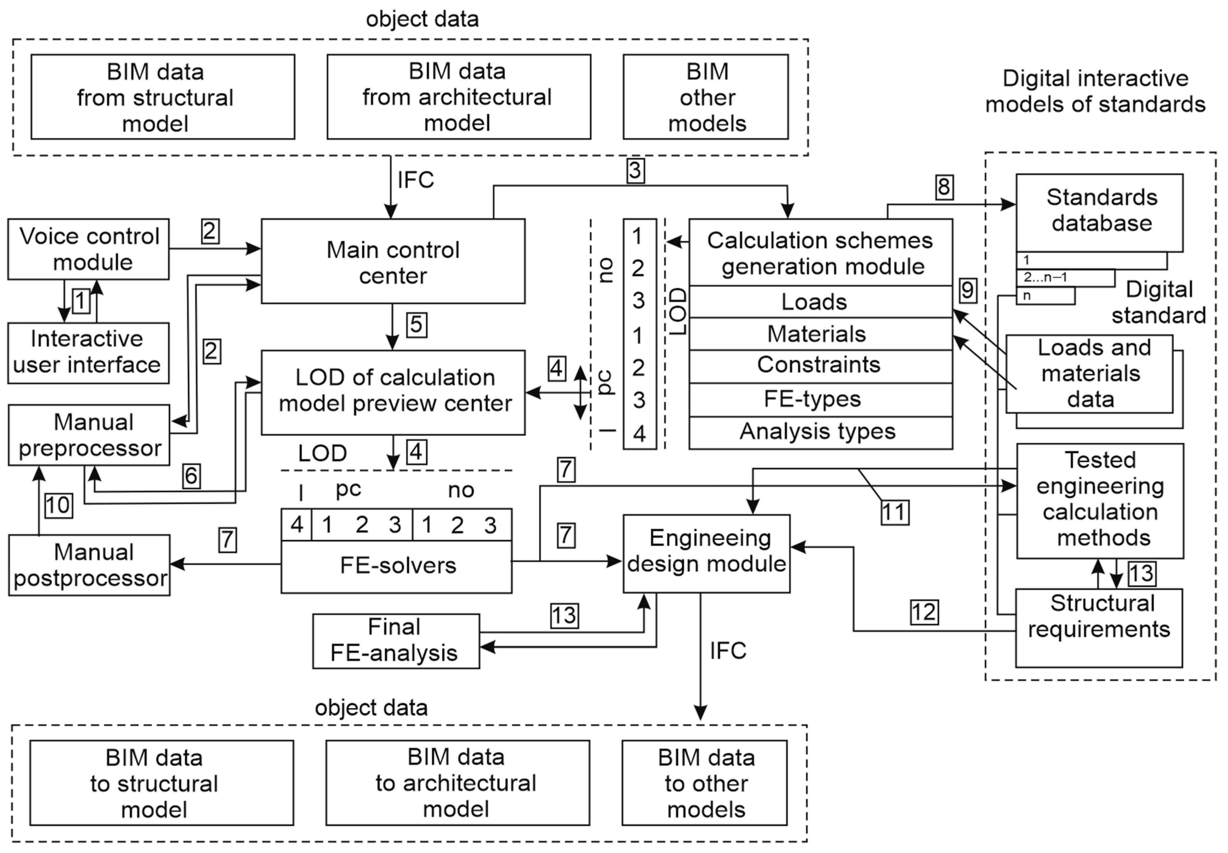
- Using advanced BIM technologies (Section 2.1.1) to develop the concept for an expert system for calculations justifying structural solutions. Emergency situations were considered on top of standard operating conditions. In this connection, three levels of detail were introduced into a calculation model (Section 2.1.2).
- Describing specific principles underlying the implementation of approaches aimed at designing a finite-element model for various levels of detail of beam and beam-plate models (Section 2.2); generating a workspace to ensure the interaction between the expert system and the digital models of regulatory documents.
- Using LODs to validate calculation models by comparing them with the experimental data (Section 3.1.1 and Section 3.1.2); providing a practical example of the calculation of a real building structure and evaluating its mechanical safety.
2. Materials and Methods
2.1. Statement of the Research Problem
2.1.1. General Concept of an Expert System for Calculating Building Structures for Information Modeling Purposes
2.1.2. Levels of Detail of a Calculation Model
- -
- “LODcm-100no”. At this level, static calculations were performed in the linear formulation using simplified schemes based on beam models. On top of finite-element models, automatable methods of manual analytical calculations, based on fundamental provisions of structural mechanics, can be used.
- -
- “LODcm-200no”. Here, static calculations took into account physical geometric, structural non-linearity. At this stage, they were brought to maximum static equivalents in the case of dynamic loading. This was possible due to the application of dynamical ratios and supplementary dynamic loading. At this stage, calculations can take account of sequential supplementary loading that describes the sequential erection of building floors. Calculation models may include plates, beams, and shells.
- -
- “LODcm-300no”. Here, the dynamic analysis, based on the modal analysis or direct integration of equations of motion, was made. All kinds of nonlinearities, damping properties of materials, inertial properties of the medium, primary and secondary imperfections, developed in the course of operation, were taken into account. A change of loads in time was taken into account; contact interactions, erosion, birth and death of elements were also considered. Complex material models were considered, including three-phase soil, packs of layers of mutually perpendicular plywood, shear layers, etc. The possibility of interaction between the soil base and the structure was taken into account. In general, beams, plates, shells, 3D elements, and all other special kinds of elements were applied here to simulate the actual behavior of a structure.
- -
- “LODcm-100pc”. A static or quasi-static calculation was considered here, taking into account the physically nonlinear behavior of the material of a damaged structure. Simplified beam models were used. A single local damage was considered within the framework of one most probable accident scenario. The local damage was considered instantaneous.
- -
- “LODcm-200pc”. The dynamic calculation of a damaged structure with physical, geometric and structural nonlinearity was considered. Several accident development scenarios were taken into account in case of a single damage. The calculation scheme encompassed the soil base modeled using simplified models (Winkler, Pasternak models, etc.) Beams, plates, shells, and their combinations were used.
- -
- “LODcm-300pc”. At this level, all calculations described at the “LODcm-300no” level were employed, but they were applied to a damaged system. Additionally, numerous local damages and their scenarios can be taken into account here. Features of transient dynamic processes, related to (1) the consecutively developing inability of elements to take loads, (2) the contact interaction with other structures or soil in an emergency situation were considered in detail.
- -
- “LODcm -400i”. This level encompassed research as part of the scientific support of projects. Most of calculations were made using 3D finite element schemes. Specific loads and impacts, such as cyclic sign variable loads, repetitive impacts, thermomechanical loads, and other extraordinary natural and man-induced impacts were modeled here.
2.2. Implementation of Numerical Modeling
2.2.1. Beam Calculation Models
- -
- Spatial beam (“Rod”, “Beam”);
- -
- Spatial beam with a cross section whose dimensions vary along its length;
- -
- Curved beam.
- Defining an object (primitive) or a group of objects, which will be replaced by a straight line, on which finite elements will be generated;
- Getting this line to pass through the points of the centers of gravity of the edge sections;
- Determining or selecting the step of the straight line partitioning, geometric characteristics and orientation of the section of a beam finite element.
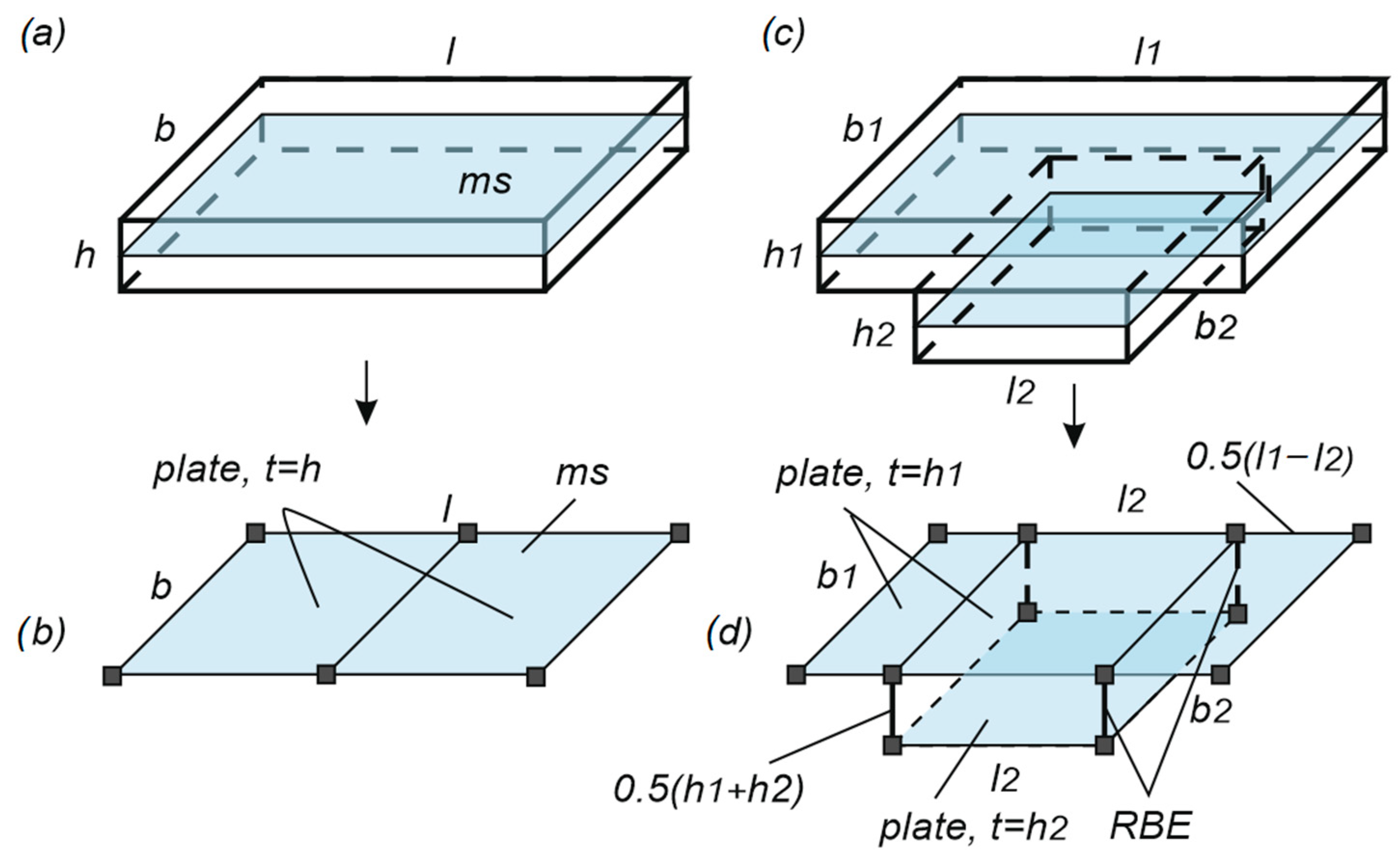
2.2.2. Plate and Plate-Beam Models
2.3. Digital Model of an Interactive Regulatory Document
- -
- Entry of general input data;
- -
- Entry of specialized data for the regulations of a particular type;
- -
- Entry of initial data about structural elements, forces, stresses and deformations inside them;
- -
- Verification of conditions of general and local strength, stiffness, general and local stability;
- -
- Analysis of data about the structural elements entered into the system; correction of non-compliances with the structural requirements;
- -
- Output of the SSS evaluation results and a corrected version of the structural solution.
- -
- Strength characteristics of steel determined taking into account the group of structures, design temperature, impact ductility and chemical composition requirements;
- -
- Welding materials;
- -
- Bolted connection materials;
- -
- Requirements for structures made of profiled or rolled plates;
- -
- Requirements for cables, ties, elements of pre-stressed structures.
2.4. Safety Evaluation of Design Solutions at Different Levels of Detail
2.5. Economic and Other Aspects of Benefits
3. Results
3.1. Experimental Verification of Calculation Models at Different Levels of Detail
3.1.1. The Experiment: Description and Results
- Maximum vertical displacements of the beam at point D (Figure 6);
- Maximum vertical displacements of the beam at the point of the beam support by the middle column;
- Deformations in the characteristic directions for the edge column and the beam.
3.1.2. Comparison of Modeling Results with Experimental Data, Taking into Account the Levels of Detail
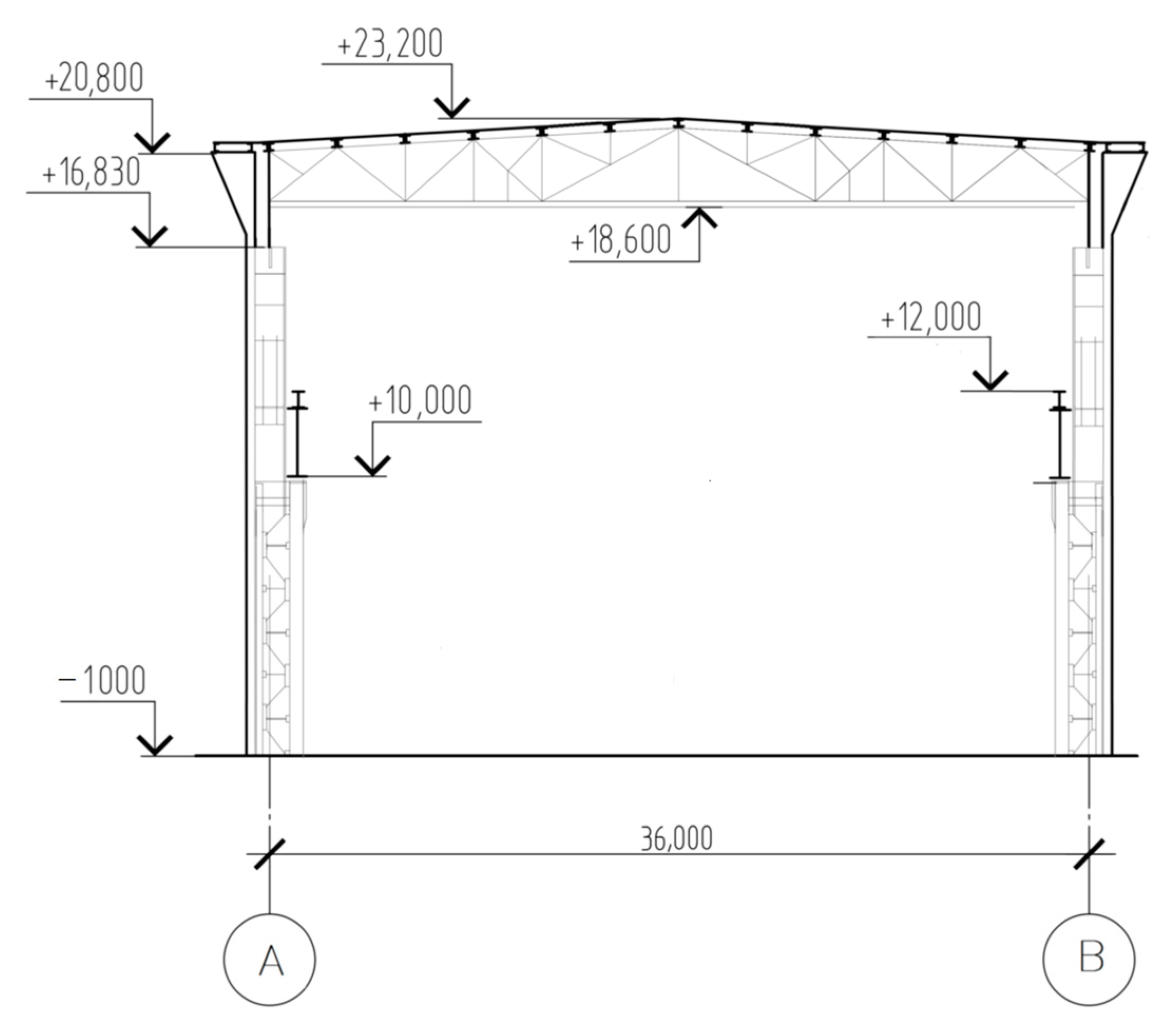
3.2. The Case of Calculation of an Industrial Building Frame
- -
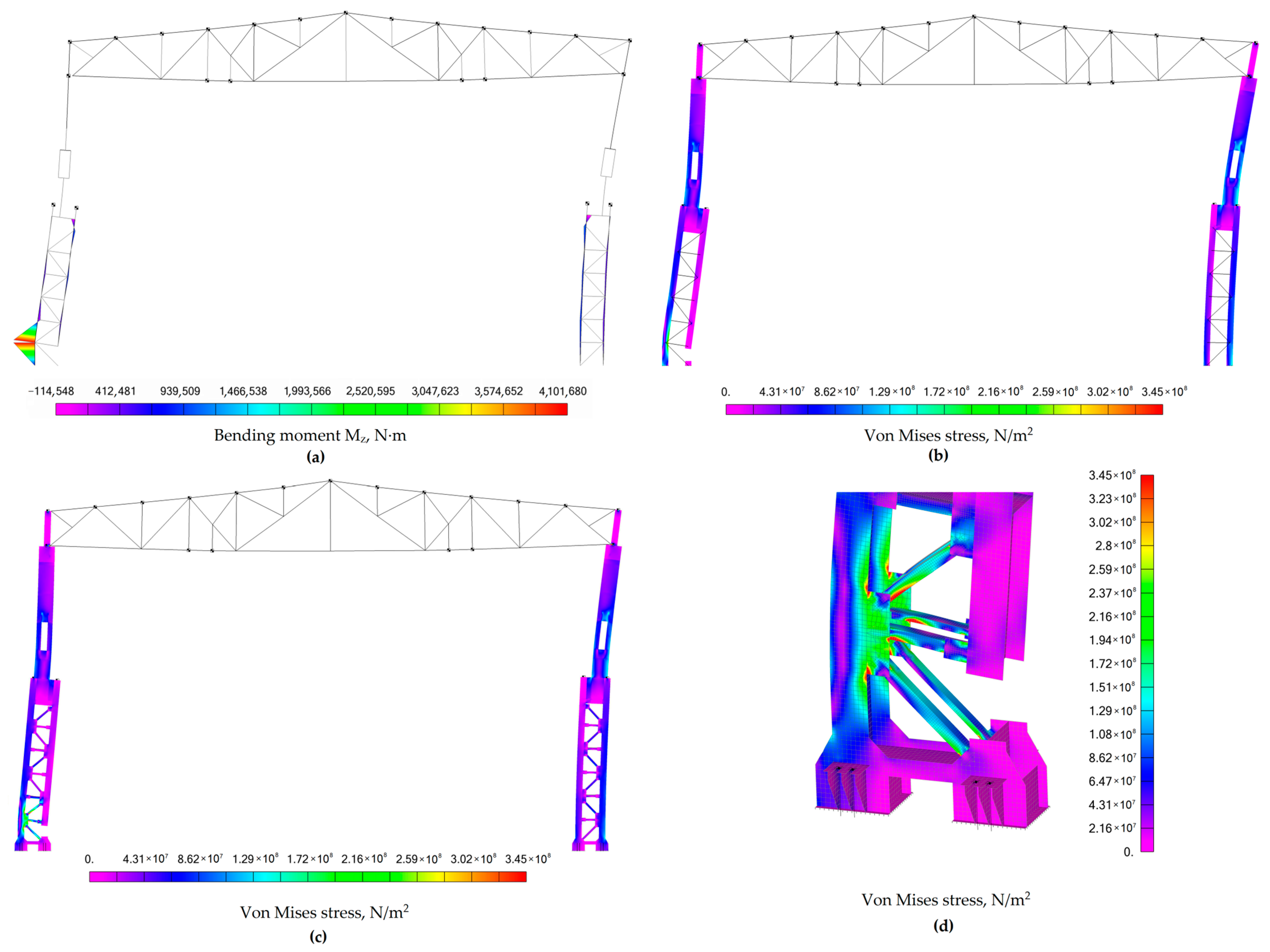
- LODcm-100pc. The frame was modeled using “beam” elements only (see Figure 9a). Joints of structural elements, which do not take substantial bending moments, were idealized as hinges. Supporting connections were assumed to be absolutely rigid.
- -
- LODcm-200pc. Structural elements of the column were modeled using “plate” finite elements, and mesh elements were modeled using “beam” elements, as at the previous level (Figure 9b). Other parameters of the model remained the same as at the previous level of detail.
- -
- LODcm-300pc. The column was modeled using finite elements of the “plate” type only (Figure 9c). The calculation showed actual connection stiffness values of structural elements without any structural simplification.
- -
- Analysis, made in the quasi-static formulation, whereby the column element removal was modeled using the static equivalent of a dynamic reaction, applied to the system in the direction opposite to the actual reaction of the column;
- -
- Analysis in the dynamic formulation, whereby reactions or forces were applied to the removed external or internal links of the system, and they were removed from the calculation scheme after the phase of dynamic relaxation. In this case, the dynamic calculation was preceded by the calculation of natural oscillations of the damaged system. This calculation determined the oscillation frequencies range, in which the shape of oscillations, typical for the emergency removal of an element, was excited.
4. Discussion and Further Investigation Prospects
5. Conclusions
- The BIM-based concept of an expert system for the design of buildings and structures, which takes into account the levels of detail of a digital calculation model and evaluates the safety of bearing systems, was proposed. Three levels of detail of a digital calculation model were introduced for cases of its normal operation (without accidents), and three levels of detail were to be applied at the onset of progressive collapse and its further localizing.
- The use of the suggested levels of detail of a calculation model system will provide more correct and rational implementation of the design process. It will reduce the time and cost of design, reduce the material consumption, and simplify the transportation and installation of structures. The required level of system reliability was provided by the limit state design. The load-bearing capacity security according to the limit state design was not less than 0.999.
- Cases of experimental verification showed that any LOD can be applied to adequately describe the actual behavior of any structure with a sufficient degree of accuracy. If it is necessary to adjust the value of SSS of joints of elements, as in the cases of emergency effects, higher order LOD, or LODcm -400i, is recommended. The case of a transverse frame structure of a building demonstrates the effective application of LOD of a digital calculation model.
Author Contributions
Funding
Institutional Review Board Statement
Informed Consent Statement
Data Availability Statement
Conflicts of Interest
References
- Cao, D.; Wang, G.; Li, H.; Skitmore, M.; Huang, T.; Zhang, W. Practices and Effectiveness of Building Information Modelling in Construction Projects in China. Autom. Constr. 2015, 49, 113–122. [Google Scholar] [CrossRef] [Green Version]
- Abdalla, S.B.; Rashid, M.; Yahia, M.W.; Mushtaha, E.; Opoku, A.; Sukkar, A.; Maksoud, A.; Hamad, R. Comparative Analysis of Building Information Modeling (BIM) Patterns and Trends in the United Arab Emirates (UAE) with Developed Countries. Buildings 2023, 13, 695. [Google Scholar] [CrossRef]
- Bui, N.; Merschbrock, C.; Munkvold, B.E. A Review of Building Information Modelling for Construction in Developing Countries. Procedia Eng. 2016, 164, 487–494. [Google Scholar] [CrossRef]
- Jung, Y.; Joo, M. Building Information Modelling (BIM) Framework for Practical Implementation. Autom. Constr. 2011, 20, 126–133. [Google Scholar] [CrossRef]
- Czmoch, I.; Pękala, A. Traditional Design versus BIM Based Design. Procedia Eng. 2014, 91, 210–215. [Google Scholar] [CrossRef]
- Bryde, D.; Broquetas, M.; Volm, J.M. The Project Benefits of Building Information Modelling (BIM). Int. J. Proj. Manag. 2013, 31, 971–980. [Google Scholar] [CrossRef] [Green Version]
- Chen, B.; Jiang, S.; Qi, L.; Su, Y.; Mao, Y.; Wang, M.; Cha, H.S. Design and Implementation of Quantity Calculation Method Based on BIM Data. Sustainability 2022, 14, 7797. [Google Scholar] [CrossRef]
- Fazli, A.; Fathi, S.; Enferadi, M.H.; Fazli, M.; Fathi, B. Appraising Effectiveness of Building Information Management (BIM) in Project Management. Procedia Technol. 2014, 16, 1116–1125. [Google Scholar] [CrossRef] [Green Version]
- Kolltveit, B.; Grønhaug, K. The Importance of the Early Phase: The Case of Construction and Building Projects. Int. J. Proj. Manag. 2004, 22, 545–551. [Google Scholar] [CrossRef]
- Volk, R.; Stengel, J.; Schultmann, F. Building Information Modeling (BIM) for Existing Buildings—Literature Review and Future Needs. Autom. Constr. 2014, 38, 109–127. [Google Scholar] [CrossRef] [Green Version]
- Pocobelli, D.; Boehm, J.; Bryan, P.; Still, J.; Grau-Bové, J. BIM for Heritage Science: A Review. Herit. Sci. 2018, 6, 30. [Google Scholar] [CrossRef] [Green Version]
- Szelag, R. The Use of BIM Technology in the Process of Analyzing the Increased Effort of Structural Elements. Procedia Eng. 2017, 172, 1073–1076. [Google Scholar] [CrossRef]
- Mahalingam, A.; Kashyap, R.; Mahajan, C. An Evaluation of the Applicability of 4D CAD on Construction Projects. Autom. Constr. 2010, 19, 148–159. [Google Scholar] [CrossRef]
- Wang, T.; Chen, H.M. Integration of Building Information Modeling and Project Management in Construction Project Life Cycle. Autom. Constr. 2023, 150, 104832. [Google Scholar] [CrossRef]
- Staub-French, S.; Khanzode, A. 3D and 4D Modeling for Design and Construction Coordination: Issues and Lessons Learned. J. Inf. Technol. Constr. 2007, 12, 381–407. [Google Scholar]
- Latiffi, A.A.; Brahim, J.; Mohd, S.; Fathi, M.S. Building Information Modeling (BIM): Exploring Level of Development (LOD) in Construction Projects. Appl. Mech. Mater. 2015, 773–774, 933–937. [Google Scholar] [CrossRef] [Green Version]
- Siccardi, S.; Villa, V. Trends in Adopting BIM, IoT and DT for Facility Management: A Scientometric Analysis and Keyword Co-Occurrence Network Review. Buildings 2023, 13, 15. [Google Scholar] [CrossRef]
- Biljecki, F.; Ledoux, H.; Stoter, J. An Improved LOD Specification for 3D Building Models. Comput. Environ. Urban. Syst. 2016, 59, 25–37. [Google Scholar] [CrossRef] [Green Version]
- Bertin, I.; Mesnil, R.; Jaeger, J.M.; Feraille, A.; Le Roy, R. A BIM-Based Framework and Databank for Reusing Load-Bearing Structural Elements. Sustainability 2020, 12, 3147. [Google Scholar] [CrossRef] [Green Version]
- Grytting, I.; Svalestuen, F.; Lohne, J.; Sommerseth, H.; Augdal, S.; Lædre, O. Use of LoD Decision Plan in BIM-Projects. Procedia Eng. 2017, 196, 407–414. [Google Scholar] [CrossRef]
- Abualdenien, J.; Borrmann, A. A Meta-Model Approach for Formal Specification and Consistent Management of Multi-LOD Building Models. Adv. Eng. Inform. 2019, 40, 135. [Google Scholar] [CrossRef] [Green Version]
- Singh, M.M.; Geyer, P. Information Requirements for Multi-Level-of-Development BIM Using Sensitivity Analysis for Energy Performance. Adv. Eng. Inform. 2020, 43, 101026. [Google Scholar] [CrossRef]
- da Inojosa, L.S.P.; de Vilanova, K.A. BIM Interoperability in the Maintenance Planning Process for Existing Buildings. J. Build. Pathol. Rehabil. 2023, 8, 45. [Google Scholar] [CrossRef]
- Chong, O.W.; Baker, C.; Afsari, K.; Zhang, J.; Roach, M. Integration of BIM Processes in Architectural Design, Structural Analysis, and Detailing: Current Status and Limitations. Selected Papers from the Construction Research Congress 2020. In Proceedings of the Construction Research Congress 2020: Computer Applications, Tempe, AZ, USA, 8–10 March 2020; pp. 1203–1212. [Google Scholar] [CrossRef]
- Alekseytsev, A.V. Mechanical safety of reinforced concrete frames under complex emergency actions. Mag. Civ. Eng. 2021, 103, 10306. [Google Scholar] [CrossRef]
- Alekseytsev, A.V.; Kurchenko, N.S. Safety of Reinforced Concrete Columns: Effect of Initial Imperfections and Material Deterioration under Emergency Actions. Buildings 2023, 13, 1054. [Google Scholar] [CrossRef]
- Sheward, H. BIM Based Normative Calculations for Early Stages of Building Design. Am. J. Civ. Eng. Archit. 2021, 9, 181–202. [Google Scholar] [CrossRef]
- Beach, T.H.; Rezgui, Y.; Li, H.; Kasim, T. A Rule-Based Semantic Approach for Automated Regulatory Compliance in the Construction Sector. Expert. Syst. Appl. 2015, 42, 5219–5231. [Google Scholar] [CrossRef] [Green Version]
- Lu, Y.; Li, Q.; Zhou, Z.; Deng, Y. Ontology-Based Knowledge Modeling for Automated Construction Safety Checking. Saf. Sci. 2015, 79, 11–18. [Google Scholar] [CrossRef]
- Eastman, C.; Lee, J.M.; Jeong, Y.S.; Lee, J.K. Automatic Rule-Based Checking of Building Designs. Autom. Constr. 2009, 18, 1011–1033. [Google Scholar] [CrossRef]
- Jiang, L.; Shi, J.; Wang, C. Multi-Ontology Fusion and Rule Development to Facilitate Automated Code Compliance Checking Using BIM and Rule-Based Reasoning. Adv. Eng. Inform. 2022, 51, 101449. [Google Scholar] [CrossRef]
- Choi, J.; Choi, J.; Kim, I. Development of BIM-Based Evacuation Regulation Checking System for High-Rise and Complex Buildings. Autom. Constr. 2014, 46, 38–49. [Google Scholar] [CrossRef]
- Alekseytsev, A.V.; Nadirov, S.H. Scheduling Optimization Using an Adapted Genetic Algorithm with Due Regard for Random Project Interruptions. Buildings 2022, 12, 2051. [Google Scholar] [CrossRef]
- Elsanadedy, H.; Sezen, H.; Abbas, H.; Almusallam, T.; Al-Salloum, Y. Progressive Collapse Risk of Steel Framed Building Considering Column Buckling. Eng. Sci. Technol. Int. J. 2022, 35, 101193. [Google Scholar] [CrossRef]
- Elsanadedy, H.M.; Almusallam, T.H.; Alharbi, Y.R.; Al-Salloum, Y.A.; Abbas, H. Progressive Collapse Potential of a Typical Steel Building Due to Blast Attacks. J. Constr. Steel Res. 2014, 101, 143–157. [Google Scholar] [CrossRef]
- Caredda, G.; Makoond, N.; Buitrago, M.; Sagaseta, J.; Chryssanthopoulos, M.; Adam, J.M. Learning from the Progressive Collapse of Buildings. Dev. Built Environ. 2023, 15, 100194. [Google Scholar] [CrossRef]


| Sensor in Figure 6 | Post-Oscillation Value | |
|---|---|---|
| Sensor Deformation | Stresses , MPa | |
| G1 | 200 | |
| G2 | 203 | |
| G3 | −159 | |
| G4 | −157 | |
| Loading Stage | Maximum Value (Dynamics) | Static Value (Post-Oscillation Value) | |
|---|---|---|---|
| (Refer to Table 1 for D) | |||
| 1 | 2.05 | 1.2 | 13 |
| 2 | 4.5 | 2.3 | 25 |
| 3 | 7.3 | 3.8 | 45 |
| Loading Stage | Maximum Value (Dynamics) | Static Value (Post-Oscillation Value) | Level of Detail | ||||
|---|---|---|---|---|---|---|---|
| LODcm | |||||||
| 1 | 2.75 | −25.45 | 1.90 | −36.84 | 15.10 | −13.90 | 100pc |
| 2.03 | 0.98 | 1.46 | −17.80 | 13.08 | −0.61 | 200pc | |
| 2.09 | −1.91 | 1.49 | −19.46 | 13.22 | −1.66 | 300pc | |
| 2 | 4.48 | 0.44 | 3.10 | −25.80 | 24.60 | 1.62 | 100pc |
| 3.31 | 35.95 | 2.37 | −2.95 | 21.30 | 17.37 | 200pc | |
| 3.41 | 31.96 | 2.42 | −4.95 | 21.53 | 16.11 | 300pc | |
| 3 | 7.86 | −7.12 | 5.44 | −30.14 | 43.15 | 4.28 | 100pc |
| 5.80 | 25.86 | 4.16 | −8.65 | 37.37 | 20.41 | 200pc | |
| 5.98 | 22.07 | 4.25 | −10.58 | 37.77 | 19.14 | 300pc | |
| Sensor | Post-Oscillation Value | |||||
|---|---|---|---|---|---|---|
| LODcm-100pc | LODcm-200pc | LODcm-300pc | ||||
| , MPa | , MPa | , MPa | ||||
| G1 | 194.03 | 2.98 | 155.72 | −22.14 | 155.30 | −22.35 |
| G2 | 194.03 | 4.43 | 155.72 | −23.29 | 155.30 | −23.50 |
| G3 | −164.60 | −3.52 | −172.65 | −8.58 | −172.13 | −8.26 |
| G4 | −164.60 | −4.84 | −172.65 | −9.97 | −172.13 | −9.64 |
| No. | Origin of Loading | Loading Safety Factor, γf,i | Reliability Safety Factor, γn | Type of Loading | Duration Factor, kdur,i |
|---|---|---|---|---|---|
| 1 | Dead load– bearing structures | 1.05 | 1.1 | Constant load | 1 |
| 2 | Dead load–roof | 1.05 | 1.1 | Constant load | 1 |
| 3 | Dead load–walls | 1.3 | 1.1 | Constant load | 1 |
| 4 | Dead load–platforms | 1.05 | 1.1 | Constant load | 1 |
| 5 | Snow load | 1.4 | 1.1 | Short-term load | 0.5 |
| 6 | Wind load | 1.4 | 1.1 | Short-term load | 0 |
| 7 | Vertical crane load | 1.2 | 1.1 | Short-term load | 0.7 |
| 8 | Horizontal crane load | 1.2 | 1.1 | Short-term load | 0 |
| 9 | Payload | 1.3 | 1.1 | Short-term load | 0.35 |
| Structure | Element | Cross-Section | Pos | Dimensions | Stiffness |
|---|---|---|---|---|---|
| 1 | 2 | 3 | 4 | 5 | 6 |
| Under-crane part of the column | Branches and braces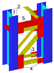 | Branches welded I-section | 1 | web −570 × 20 | t20 |
| 2 | flanges −400 × 30 | t30 | |||
| Braces Single hot rolled angle | 3 | L125 × 10 | t10 | ||
| Gusset | 4 | −12 | t12 | ||
| Diaphragm (3 m each) | 5 | −12 | t12 | ||
Base of column | Traverse | 1 | −800 × 500 × 30 | t30 | |
| Base plate | 2 | −800 × 700 × 50 | t50 | ||
| Transverse ribs | 3 | −500 × 250 × 16 | t16 | ||
| Anchor plate | 4 | −600 × 500 × 30 | t30 | ||
| Reinforcing ribs | 5 | −600 × 450 × 20 | t20 | ||
Under-crane with overhead part connection | Traverse beam | 1 | web −1480 × 25 | t25 | |
| 2 | flanges −570 × 20 | t20 | |||
| Stiffeners of lower flange | 3 | 2–300 × 16 | t16 | ||
| Rib under column flange | 4 | −20 | t20 | ||
| Above column rack | Rack | Welded I-section | 1 | web −380 × 6 | t6 |
| 2 | flanges −300 × 10 | t10 | |||
| Base plate | 3 | −400 × 300 × 30 | t30 | ||
| Overhead part of the column | Column rod | Column rod Welded I-section | 1 | web −980 × 12 | t12 |
| 2 | flanges −500 × 20 | t20 | |||
| Opening for passageway | 3 | web −280 × 12 | t12 | ||
| 4 | flange −400 × 20 | t20 | |||
| Stiffening rib | 5 | −16 | t16 | ||
Column head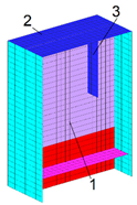 | Web | 1 | −980 × 25 | t25 | |
| End plate | 2 | −1000 × 500 × 30 | t30 | ||
| Support rib on the web | 3 | −600 × 300 × 30 | t30 |
| Calculation | Parameter | Level of Detail | |||||
|---|---|---|---|---|---|---|---|
| LODcm-100pc | LODcm-200pc | LODcm-300pc | |||||
| Max | Stable | Max | Stable | Max | Stable | ||
| Quasi-static approach LODcm-100pc k = 1.539 (6) LODcm-200pc k = 1.547 (6) LODcm-300pc k = 1.506 (6) | Vertical displacement of a collapsed column element, mm | 15.71 | 11.09 | 14.27 | 9.84 | 12.31 | 8.65 |
| Horizontal displacement of the column at the point of the rail-to-column connection, mm | 80.92 | 56.99 | 72.27 | 50.19 | 64.09 | 45.27 | |
| Normal stresses in the pillar, MPa | −426.1 | −313.3 | −300.0 | −219.5 | −291.1 | −217.7 | |
| Normal stresses in the top element of the column above the traverse beam, MPa | −162.7 | −124.8 | −173.6 | −132.4 | −157.6 | −122.8 | |
| Dynamic approach | Vertical displacement of a collapsed column element, mm | 15.13 | 11.09 | 13.23 | 9.69 | 11.52 | 8.43 |
| Horizontal displacement of the column at the point of the rail-to-column connection, mm | 85.34 | 56.98 | 72.96 | 49.54 | 65.55 | 44.26 | |
| Normal stresses in the outer column element, MPa | −402.9 | −313.3 | −301.3 | −237.1 | −294.8 | −233.1 | |
| Normal stresses in the top element of the column above the traverse beam, MPa | −139.6 | −124.8 | −130.3 | −113.1 | −131.9 | −120.7 | |
| Parameter | LODcm-100pc | LODcm-200pc | LODcm-300pc | |||
|---|---|---|---|---|---|---|
| Max | ∆ | Max | ∆ | Max | ∆ | |
| Vertical displacement of a collapsed column element, mm | 15.71 | 3.83% | 14.27 | 7.86% | 12.31 | 6.86% |
| Horizontal displacement of the column at the point of the rail-to-column connection, mm | 80.92 | −5.18% | 72.27 | −0.95% | 64.09 | −2.23% |
| Normal stresses in the outer column element, MPa | −425.1 | 5.75% | −300.0 | −0.44% | −291.1 | −1.27% |
| Normal stresses in the top element of the column above the traverse beam, MPa | −162.7 | 14.20% | −173.6 | 24.92% | −157.6 | 16.32% |
Disclaimer/Publisher’s Note: The statements, opinions and data contained in all publications are solely those of the individual author(s) and contributor(s) and not of MDPI and/or the editor(s). MDPI and/or the editor(s) disclaim responsibility for any injury to people or property resulting from any ideas, methods, instructions or products referred to in the content. |
© 2023 by the authors. Licensee MDPI, Basel, Switzerland. This article is an open access article distributed under the terms and conditions of the Creative Commons Attribution (CC BY) license (https://creativecommons.org/licenses/by/4.0/).
Share and Cite
Tusnina, O.; Alekseytsev, A. LOD of a Computational Numerical Model for Evaluating the Mechanical Safety of Steel Structures. Buildings 2023, 13, 1941. https://doi.org/10.3390/buildings13081941
Tusnina O, Alekseytsev A. LOD of a Computational Numerical Model for Evaluating the Mechanical Safety of Steel Structures. Buildings. 2023; 13(8):1941. https://doi.org/10.3390/buildings13081941
Chicago/Turabian StyleTusnina, Olga, and Anatoly Alekseytsev. 2023. "LOD of a Computational Numerical Model for Evaluating the Mechanical Safety of Steel Structures" Buildings 13, no. 8: 1941. https://doi.org/10.3390/buildings13081941