Abstract
Steel structures have been widely used in large public venues and super-high-rise buildings due to their strong spatial flexibility, good seismic performance, and beautiful appearance. For buildings with high lighting requirements, such as shopping malls, stadiums, and exhibition halls, a super-large day-lighting roof with light-transmitting steel structures is to be designed on top. However, it is impossible to directly hoist large steel structures with cranes in buildings, and the installation of steel structures at uneven roof elevations usually requires full hall scaffolding, which is inefficient and time-consuming. Based on the existing construction methods, this paper proposes a construction technology for column replacement integral accumulation sliding at uneven elevations for steel structures. This technology can improve the construction efficiency and reduce the construction cost of steel structures at uneven elevations.
1. Introduction
In recent years, the use of steel structures in the construction of large public buildings has become increasingly popular due to their excellent seismic performance, lightweight nature, and high strength [1,2,3,4]. To meet the lighting requirements of such buildings, light-transmitting materials like glass are often incorporated into oversized steel structures situated atop them (see Figure 1).

Figure 1.
Oversized light-filled roof (The Parisian Macao Resort Hotel).
However, during the installation of large steel roof trusses, conventional scaffolding methods have proven to be costly, time-consuming, and complex [5]. Moreover, limited construction sites pose challenges for direct crane lifting within the building [6,7]. Nevertheless, technological advancements have led to the development of integral and segmented assembly methods with cumulative sliding [8,9,10,11,12,13]. It is important to note that these methods have limitations when it comes to uneven elevations. To address this issue, a column replacement integral accumulative sliding technology has been proposed, enabling the sliding of trusses with columns at different elevations [14]. Ensuring the safe and efficient construction of large prefabricated steel structures is particularly crucial for countries undergoing extensive development.
The theoretical research in this field focuses on the development of integral pulling and accumulating column replacement sliding construction technology for steel structures at uneven elevations. Its primary goal is to investigate the structural response of large steel structures with unequal heights and analyze the mechanical properties of segmental cumulative assembly, partial column replacement, and integral pulling and sliding for such structures. Additionally, an engineering practice analysis aims to develop construction technologies that utilize integral pulling and cumulating column replacement sliding for uneven-height planes. These technologies can be extended and applied in mountainous areas or locations with uneven ground levels. A technology roadmap depicting the proposed process is illustrated in Figure 2. The key technologies involved the integration of assembled cumulative sliding, hydraulic synchronized sliding, hydraulic crawler propulsion, unloading construction, and computer process monitoring and synchronization control. The main processes of the assembled cumulative sliding technology involve laying sliding tracks, lifting the steel structure onto the roof, and assembling cumulative sliding steel roof frames in sections. The hydraulic synchronized sliding focuses synchronized control on the hydraulic cylinder, position, and land. The hydraulic crawler propulsion technique uses a self-locking hydraulic crawler as driving equipment for a hydraulic sliding system. Unloading construction considers the hydraulic unloading system and the unloading construction process.
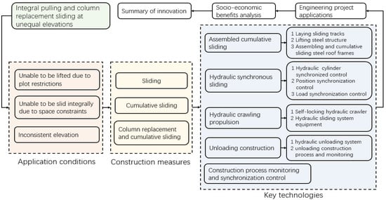
Figure 2.
Technology roadmap.
2. The Construction Technology of Column Replacement Integral Accumulation Sliding at Uneven Elevation for Steel Structures
This study proposes innovative technologies for the assembly, column replacement, accumulation sliding, and overall positioning of large steel structures at uneven plane elevations. The process, as depicted in Figure 3, involves lifting the steel structure onto the roof, laying sliding tracks, sequentially lifting steel components to the rooftop working platform, assembling steel roof frames in sections, sliding the sections along designated tracks, utilizing temporary transition steel columns for areas with elevation differences, elevating the steel roof frames as a whole, dismantling the sliding tracks, and achieving fixation and installation through welding and high-strength bolts. The core technologies in this approach are the column replacement and accumulation sliding technologies, as well as the hydraulic synchronized sliding technique, which play a crucial role in the construction process.
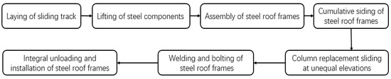
Figure 3.
Complete construction process of integrally pulling and column replacement cumulative sliding at uneven elevation.
The process of constructing steel structures using integral accumulation sliding with column replacement at uneven elevations is meticulous and sequential. The process begins with the elevation of steel components to the roof working platform and the installation of a sliding track. The steel roof frame is then assembled in sections at the end of the roof, comprising two roof frames and steel columns per section. These assembled sections are subsequently lifted onto the sliding track. The process continues as each section is slid to its predetermined position through a fixed point, followed by the assembly and sliding of the subsequent section. This iterative procedure repeats until all roof frames are appropriately positioned. In areas with varying elevations, temporary columns may be established to facilitate the movement of the roof frames. Once all sections are in place, the entire steel roof frame is elevated using a jack and permanently secured after removing the sliding track. Finally, the steel roof structure is reinforced and fastened through welding and bolting techniques. Figure 4 demonstrates the construction process of column replacement and the accumulation sliding technique.
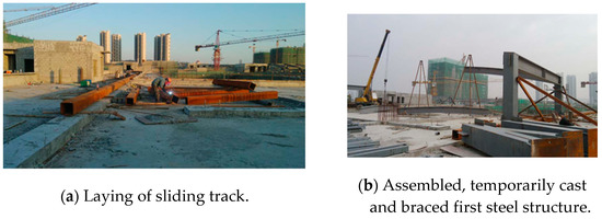
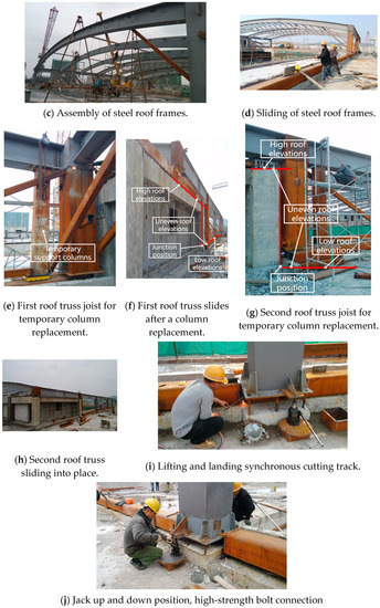
Figure 4.
Illustration of column replacement and accumulation sliding construction process.
The fundamental principle of the integrated tension-cumulative sliding roof construction technology addresses the challenge posed by varying roof elevations, rendering traditional lifting and sliding methods inapplicable to the steel roof truss [15,16]. To overcome this, the truss is initially slid to the junction position between the high and low spans. Subsequently, strategically positioned temporary support columns serve two primary purposes: supporting the top beam and replacing the original sliding columns. With the steel roof truss raised or lowered, sequential sliding operations can smoothly proceed to subsequent steps. Figure 5 illustrates the detailed operations of column replacement for the top beam, which include the following steps:
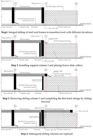
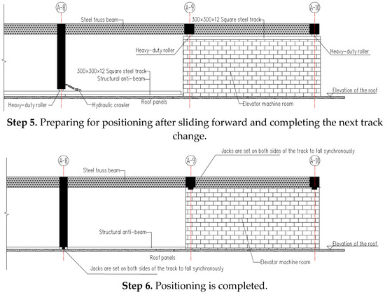
Figure 5.
Illustration of column replacement and accumulation sliding construction process.
- Step 1: The initial step in the construction process involves sliding the entire steel roof truss to the intersection point between the high and low spans of the roof. However, due to variations in roof elevations, the sliding column 1, which provides support to the truss, faces obstacles that prevent it from continuing forward, such as the presence of an elevator machine room.
- Step 2: To address this challenge, a temporary support column (referred to as support column 1) is installed behind sliding column 1. This support column is equipped with heavy-duty rollers at its base and is designed based on considerations such as the load and dimensions of the top beam. It serves as a temporary support structure for the top beam. Additionally, horizontal tie beams or scissor braces are introduced to ensure the overall stability of the steel roof truss and mitigate the risk of overturning.
- Step 3: Once the necessary preparations are in place, sliding column 1 is removed, allowing for the forward sliding of the steel roof truss. Heavy-duty rollers are positioned beneath the beam of the original sliding column 1 to facilitate smooth movement. Hydraulic jacks are utilized to elevate the steel roof truss structure, ensuring the proper installation of the heavy-duty rollers. Subsequently, the load from the hydraulic jacks is released, enabling support column 1 and the truss beam to effectively bear the load, thereby completing the first track change.
- Step 4: The construction process continues with the sliding of the steel roof truss along the upper track. Following the successful transition of the support structure to accommodate the varying elevations, support column 1 is removed, allowing for the continued forward sliding of the truss.
- Step 5: The subsequent columns of the steel roof frames are replaced using the same methodological sequence, ensuring that each frame is appropriately slid into its designated position.
- Step 6: Within the permissible range of rotation for the steel structure, spiral jacks are employed to sequentially lower each steel column into its designated position. Throughout this process, the sliding track is gradually dismantled, ultimately leading to the completion of the positioning phase.
3. Hydraulic Synchronized Sliding Technology
Hydraulic synchronized sliding technology enables the smooth and coordinated movement of large structures using a hydraulic system. It ensures precise positioning and assembly of components, providing an efficient and controlled solution for structural relocation in complex projects [17,18].
The technology employs a self-locking hydraulic crawler as the sliding driving equipment, featuring wedge-shaped clamps that provide a reverse self-locking function for enhanced construction safety [19]. The hydraulic cylinder controls the sliding track’s state by retracting and extending, tightening the clamps during extension to lock the track, and releasing them during retraction to facilitate object sliding. This self-locking hydraulic crawler offers advantages such as synchronized control, time and labor savings, and high positioning accuracy, eliminating the need for a counterforce frame. Compared to conventional hydraulic traction equipment, hydraulic synchronized crawling devices demonstrate superior load-bearing efficiency in confined spaces and elevated heights, eliminate the need for counterforce frames, preserve component and concrete structure integrity, distribute stress through multipoint sliding, ensure safety through self-locking capabilities, and provide convenient operation through high automation. Overall, these devices offer a compact and efficient solution for component movement.
3.1. Synchronized Control of Hydraulic Cylinder Movements
The central master computer system coordinates the hydraulic cylinder movements based on signals from the control ball and hydraulic cylinders. The control system determines the precise position of each cylinder using feedback signals and transmits unified command signals to the cylinder pump stations. This ensures real-time control of the cylinder extension speed and synchronized operation of all hydraulic cylinders. Refer to Figure 6 for a visual representation of the synchronous control of hydraulic cylinder movements.
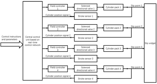
Figure 6.
Synchronized control of hydraulic cylinder movements.
3.2. Position Synchronization Control
To achieve synchronized positioning of the steel roof frame during the sliding process, a precise control mechanism is implemented. A designated main order sliding point is established on the sliding track, while other points are positioned in accordance with this reference. The main order sliding point is configured with constant ratio valve current and opening, as per user specifications, ensuring the consistent and controlled extension speed of the main sliding cylinder. This results in the gradual and steady movement of the main order point at a fixed speed. The remaining points along the sliding track regulate their sliding speed based on the displacement magnitude from the main command point. The primary objective is to maintain a uniform distance between the following points and the command point, as dictated by the main control computer. This is accomplished by comparing the displacement signals transmitted from each sensor to the main control system and subsequently adjusting the current level of the cylinder proportional valve at the corresponding position to achieve the desired displacement difference. In cases where the displacement exceeds a predefined threshold, the system activates an automatic alarm to notify personnel for prompt inspection and potential manual intervention. The position synchronization control is visually represented in Figure 7.
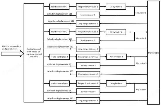
Figure 7.
Position synchronization control.
3.3. Load Synchronization Control
Load synchronization control plays a crucial role in maintaining a minimal deviation between the actual load and the theoretical load at the slip points. To achieve this objective, real-time monitoring of the sliding point’s position is essential, accompanied by the implementation of a load synchronization control scheme. Load synchronization control is implemented to maintain the synchronized position of the steel roof truss during the sliding process. When performing the sliding operation on the sliding track, a master sliding point should be designated, while other points are set as follower points. To ensure that the displacement difference between them is not significant, a speed control valve can be used in the hydraulic system for synchronization. The speed control valve has a load compensation function, which maintains the same pressure drop across the two throttle orifices. However, due to factors such as hydraulic forces and resetting springs, as well as the inherent inability to achieve absolute equality in the throttle orifices, the synchronization error of the speed control valve is generally around 5%. Furthermore, the system must be a constant-pressure system, resulting in both overflow losses and pressure losses. The control box, responsible for executing the load synchronization control strategy, is depicted in Figure 8.
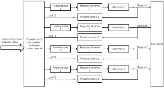
Figure 8.
Load synchronization control strategy.
4. Hydraulic Crawler Propulsion Principle and Unloading
4.1. Hydraulic Crawler Propulsion Principle
The hydraulic synchronized sliding technique employs a self-locking hydraulic crawler as the driving equipment. The self-locking hydraulic crawler is a combination structure with wedge-shaped clamps that provide a one-way self-locking action. The control of the sliding track’s retraction and driving is achieved through the extension and retraction of hydraulic cylinders. When the cylinders extend, the clamps tighten, securing the sliding track. Conversely, when the cylinders retract, the clamps loosen and move in the same direction as the cylinders, facilitating the sliding motion. The advantages of the self-locking hydraulic crawler lie in its ease of synchronous control with the sliding track, time and labor efficiency, elimination of the need for a counterforce frame, and high positioning accuracy. The working diagram of the crawler is illustrated in Figure 9. The crawler operates in the following steps:
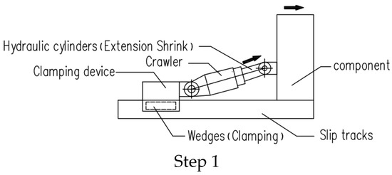
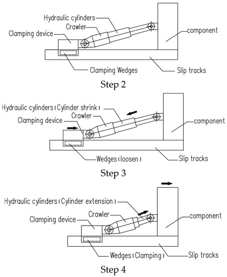
Figure 9.
Working diagram of the crawler.
- Step 1: The wedges clamp onto the sliding track, and the piston rod of the hydraulic cylinder is connected to the sliding component. The sliding component is then driven by extending the hydraulic cylinder.
- Step 2: The hydraulic cylinder extends by a travel distance of 250 mm.
- Step 3: After completing one travel distance, the sliding component remains stationary, and the wedges in the clamping device separate from the sliding track. The clamping device is then dragged forward for sliding.
- Step 4: Once a crawling push is completed, the process returns to Step 1 and repeats sequentially until the desired position is reached.
During the cumulative sliding installation process, the jacking point of the hydraulic crawler is strategically positioned at the lower steel column’s bearing location. To ensure structural stability and safety, steel sliders are installed at the support of the lower steel column along the main joist. However, due to the absence of horizontal force transmission components between adjacent steel columns in the sliding direction, substantial thrust and friction arise during the sliding process, resulting in an undesirable additional moment around the root of the steel column. To address this issue, temporary horizontal links are established between each adjacent pair of steel sliders (i.e., steel column roots) along the track direction. These horizontal links enable the sequential transmission of the hydraulic jacking equipment’s horizontal traction force from the front to the rear steel sliders, thereby ensuring the stability and controlled sliding of the steel roof frame (see Figure 10).
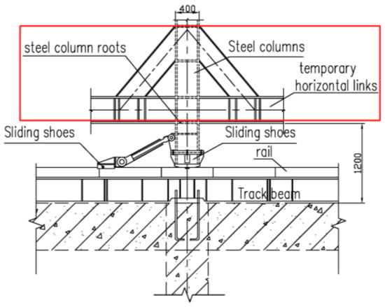
Figure 10.
Diagram of the temporary reinforcement measure.
In the case of the integral sliding of the steel structure, a comprehensive analysis of the steel structure is essential, followed by temporary reinforcement based on the analysis results. This is necessary because sliding induces concentrated stress on the steel structure, particularly in tension, leading to significant deformation if the stress concentration point is small. Therefore, thorough testing of each steel structure component is required. Key considerations include calculating the track beam’s bearing strength, determining the hoist support arrangement, and calculating the required traction force. These measures collectively contribute to the successful implementation of the sliding process and the structural integrity of the steel components.
4.2. Equipment of Hydraulic Sliding System
In order to ensure the safety and reliability of the overall system arrangement, it is imperative to achieve uniform loading of each hydraulic crawler and maintain an approximately equal distribution of hydraulic crawlers driven by each pump station [20]. The sensors employed in the system primarily consist of pressure sensors and cylinder stroke sensors. Each hydraulic cylinder is equipped with these sensors to monitor pressure and stroke measurements. Prior to finalizing the effectiveness of the computer control system arrangement, meticulous verification of sensor installation and network control system functionality is indispensable for ensuring seamless site network operation. The hydraulic sliding system equipment is summarized in Table 1.

Table 1.
The equipment of the hydraulic sliding system.
4.3. Unloading Construction Technology
In order to optimize efficiency and meet the group requirements for unloading the steel structure sliding units, significant attention has been given to achieving uniform loading across each hydraulic unloading cylinder. To accomplish this, a comprehensive unloading system diagram, as depicted in Figure 11, was devised. The unloading system encompasses multiple hydraulic pump stations, each comprising dual hydraulic circuits. These pump stations are collectively governed using a central control computer, enabling synchronous control of the system. Within the unloading system, the hydraulic pump stations are equipped with variable frequency drive motors to regulate the oil pumps. By manipulating the power supply frequency, the motor speed can be adjusted, ensuring a continuous and adjustable oil flow rate. Through the integration of electronic control and feedback detection systems, precise control over the synchronization and load distribution of the jacks during the lifting and lowering processes is achieved.
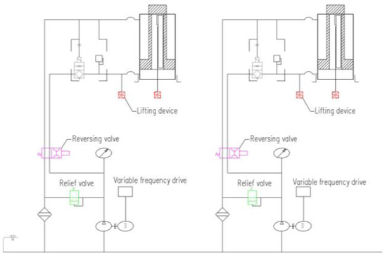
Figure 11.
Diagram of the hydraulic unloading system.
The hydraulic unloading system utilizes frequency-controlled motors to regulate the oil pump, allowing for the continuous adjustment of the oil pump flow. An electronic control and detection feedback system, along with pressure and displacement closed-loop control, ensures the precise and synchronous lifting of the jacks with balanced loads.
Upon sliding the truss structure into position, the graded unloading process commences. The track beams, sliding rails, sliders, and associated equipment are first removed. Hydraulic jacks are then used to internally lift the steel roof, following three main principles: reaction force control, cyclic jacking and dropping control, and displacement control. Figure 12 illustrates the unloading construction process.
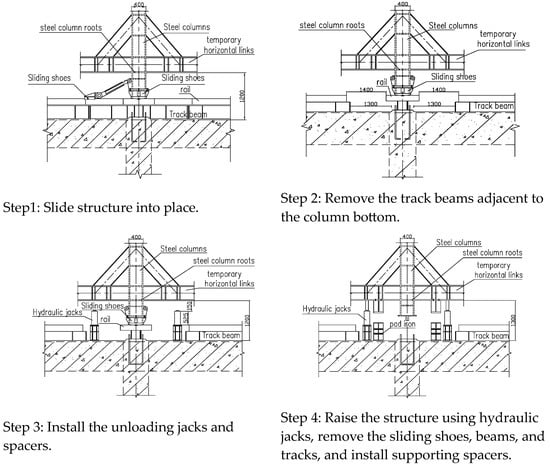
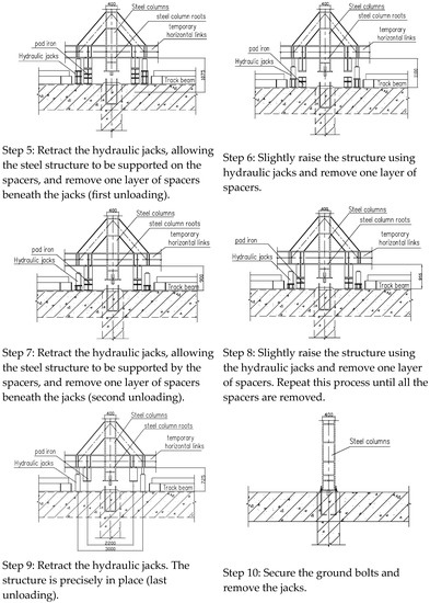
Figure 12.
Diagram of the unloading process.
To ensure compliance with specifications and design requirements regarding deflection and deformation during unloading, an electronic distance measuring device monitors displacement and deformation. Adjustments to unloading steps and volume are made based on displacement changes for operational safety. Monitoring includes the change in elevation of roof trusses, stress monitoring for each step and section, and measurement of elevation along the axial position of the entire roof truss post-unloading.
5. Construction Process Monitoring and Servo Control Technology
5.1. Construction Process Monitoring Technology
The simulation of the structural construction process enables the acquisition of mechanical properties, movement states, change characteristics, and potential failure modes for the entire construction system [21]. Key monitoring parameters, including characteristic parameters, monitoring period, monitoring area and range, and data collection frequency or periodicity, are determined.
During monitoring, focus is placed on displacements at key points and points with the largest displacements in the structural construction system, strain changes in key components or highly stressed components, and the overall displacement and velocity changes of the structure.
5.2. Construction Process Servo Control Technology
Each hydraulic cylinder is equipped with a pressure sensor on the chamber side and a stroke sensor to measure the cylinder stroke and process the cylinder pressure signal.
The sensors are connected to communication modules, and the site is connected to the real-time network control system. A computer control cabinet is installed, facilitating communication lines for proportional valves, solenoid valves, cylinder signals, and power supply. By networking all pump stations through the proportional valve and solenoid valve communication lines, connecting cylinder signal communication modules via the cylinder signal communication line, and establishing power connections for all modules, the computer control system layout is completed.
Sensor monitoring primarily obtains information on hydraulic cylinder stroke, load, and the status of the entire sliding component. This information is transmitted to the main control computer through the on-site real-time network. Based on the current cylinder displacement information, the main control computer determines the next action of the hydraulic cylinder as well as the synchronization adjustment of the entire sliding system based on load and member attitude information from the network.
Through data feedback and control command transmission, various functions such as synchronous action, load balancing, attitude correction, stress control, process display, and fault alarm can be automatically realized.
6. Application of Engineering Projects
The research results of this study have been successfully applied in various projects, including the first phase of the Shishi International Light Textile Centre, Quanzhou Decheng Hospital, Yulin Runjia Commercial Plaza, Xing Yi Square, Tianbo City Plaza, and Fuxin Jinding City. These applications have demonstrated the safety and effectiveness of the research findings, validating their wide applicability.
6.1. Project I: Shishi International Light Textile Logistics Trading Centre
The Shishi International Textile Center Project comprises a large building complex with commercial markets and office towers. The construction technique of cumulative sliding was adopted due to site limitations. The steel roof frame structure in Zone A was successfully lifted and slid into place within a construction period of 19 days, as shown in Figure 13. This method eliminated the need for full scaffolding, saving time and costs. The assembly of the steel structure on the floor ensured operational convenience and maintained project quality.
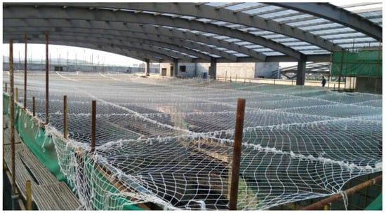
Figure 13.
Construction technology of column replacement and cumulative sliding for the Shishi International Light Textile Logistics Trading Centre (Zone A).
6.2. Project Ⅱ: Quanzhou Decheng Hospital Outpatient and Inpatient Building
The Quanzhou Decheng Hospital Outpatient and Inpatient Building Project is located in Huian County. It consists of one underground level and five above-ground levels, including outpatient medical and technical complex buildings, a hospital supporting building, and an energy center. The construction method of column replacement sliding was adopted for the inner atrium due to site limitations, as shown in Figure 14. The steel structure lifting, sliding, and column replacement were completed within a construction period of 13 days. This approach saved time and costs compared to traditional construction methods while ensuring project quality and safety.
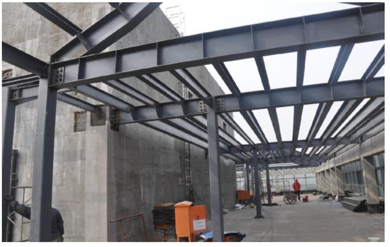
Figure 14.
Construction technology of column replacement and cumulative sliding for the Quanzhou Decheng Hospital Outpatient and Inpatient Building.
6.3. Benefit Analysis
The overall sliding and partial column replacement sliding methods result in reduced construction costs. Unlike the conventional plan that requires full scaffolding, the integral pulling cumulative column replacement sliding only incurs rental and labor fees for temporary support, jacks, and heavy load shifters. Additionally, civil and installation sub-projects can be carried out simultaneously, significantly shortening the construction period. Table 2 presents a list of the economic benefits generated by the main application.
Table 2.
List of economic benefits arising from main application.
The incremental economic benefits lie in the comparison of different construction methods. Conventional construction methods include: overall assembly on the ground followed by overall hoisting and installation and high-altitude scattered hoisting and installation. This paper proposes the method of cumulative sliding with unequal elevation for column replacement. The project objective is to achieve global optimization while adhering to the constraints of project schedule, quality, and cost. Therefore, economic benefits not only encompass costs incurred during the construction phase, such as scaffolding installation costs, manual labor for welding, crane hoisting operations, high-altitude assembly and welding workers, and other expenses, but also involve a comparison of construction durations. A project example is provided to illustrate the calculation method for economic benefit costs in Table 3. It is worth noting that project duration and construction costs are closely related. Generally, if the construction period is extended, the construction cost will increase, which in turn affects the utilization by the project owner.
Table 3.
Comparison of the economic benefits of different construction methods.
According to Table 3, it can be observed that using the method of integrally pulling and column replacement cumulative sliding can save costs by 20.47 (RMB 10,000) compared to using the method of high-altitude scattered hoisting and installation. Additionally, it can also reduce the construction duration by six days. This approach demonstrates superior economic efficiency and time savings.
The innovative construction technology of cumulative sliding for column replacement at different elevation planes has emerged as a significant advancement in the field. This novel approach not only effectively addresses the complex task of replacing columns in steel structures at various elevations, but also yields notable benefits in terms of construction efficiency, cost reduction, and enhanced construction quality. The positive reception and commendation received from supervisors, project owners, and stakeholders demonstrate the practical value and effectiveness of this technique. Furthermore, the adoption of this technology has fostered a culture of quality awareness and scientific research within the enterprise, stimulating further advancements in quality management practices. The collaborative and cooperative spirit among personnel has been nurtured, contributing to elevated levels of management proficiency and technical expertise. The knowledge and experience gained from this project serve as a valuable resource and reference for future endeavors in similar contexts.
7. Conclusions
The key technical characteristics of this construction method include column replacement sliding construction on a large-scale steel structure platform with uneven elevations. A crawler-type heavy-duty transporter and electric hoist are utilized for overall traction and cumulative sliding on a single-layer steel structure when the large-scale steel structure column is slid into the designated position; hydraulic jacks are employed to unload and precisely position the entire steel structure. This method exhibits favorable economic and social benefits.
The adoption of overall sliding and partial column replacement sliding eliminates the need for full scaffolding, thereby reducing construction costs. In conventional methods, the cost of renting and leasing the scaffolding, including labor and material expenses, is incurred. However, the overall traction and cumulative sliding method for column replacement only incurs costs for renting tracks, temporary supports, hydraulic jacks, crawler-type heavy-duty transporters, and labor for sliding. The ability to concurrently carry out civil construction and installation activities significantly shortens the construction period, resulting in substantial savings in labor and financial costs.
The innovative technique of cumulative sliding for column replacement at uneven elevations perfectly solves the construction challenges of steel structure sliding and column replacement on different elevation planes. It improves construction efficiency, reduces construction costs, and enhances construction quality, receiving unanimous praise from supervisors, clients, and the wider community.
The research and implementation of this achievement enhance the quality consciousness and research capabilities of enterprises, promote further development of quality management, foster a spirit of unity and cooperation among personnel, and improve management levels and technical efficiency. Furthermore, it provides valuable references for similar projects.
The application of large-scale steel structure traction and the cumulative sliding method on platforms with uneven elevations has great potential in the field of civil engineering and construction technology. It is particularly suitable for the construction of large-span grid structures with surrounding buildings and interior courtyards. By continuously summarizing and innovating, a series of key supporting construction techniques can be developed, including column replacement sliding and cumulative sliding for different plane configurations, assembly and cumulative sliding, hydraulic synchronous sliding, hydraulic crawler propulsion, unloading construction methods, construction process monitoring, and servo control. These techniques can be further extended for the overall sliding construction of structures on mountainous or uneven terrain. The column replacement sliding technique can also be expanded to facilitate the lateral movement of buildings at different elevations, making it particularly suitable for road widening, urban revitalization, preservation of old buildings in real estate development plots, and other scenarios. It holds significant potential for widespread application and promotion.
Author Contributions
R.R.: conceptualization, methodology, writing—original draft preparation, formal analysis, and project administration; Y.C.: conceptualization, methodology, and writing—original draft preparation; W.L.: methodology, writing—original draft preparation, and formal analysis; L.W.: methodology, writing—original draft preparation, and formal analysis; J.H.: methodology, formal analysis, and project administration. All authors have read and agreed to the published version of the manuscript.
Funding
This research was funded by the Social Science Foundation of Fujian Province (No. FJ2022C038), the Xiamen Federation of Social Science Associations and Xiamen Academy of Social Sciences (No. 2022D08, No. 2023D10), and the ‘First-class’ Discipline Construction Project of Chengyi University College, Jimei University (No. C11709).
Data Availability Statement
No new data were created or analyzed in this study. Data sharing is not applicable to this article.
Conflicts of Interest
The authors declare no conflict of interest.
References
- Shi, Y.J.; Xu, K.L.; Shi, G.; Li, Y.X. Local buckling behavior of high strength steel welded Isection flexural members under uniform moment. Adv. Struct. Eng. 2018, 21, 93–108. [Google Scholar] [CrossRef]
- Zhao, J.Y.; Li, J.; Sun, Y. Experimental and numerical study on overall buckling behavior of Q460 high-strength steel continuous beams with welded singly symmetric I-section. Eng. Struct. 2023, 280, 115678. [Google Scholar] [CrossRef]
- Ran, H.D.; Chen, Z.P.; Ma, Y.M.; Obrien, E.; Sun, Y. Experimental and numerical study of laser-welded stainless steel slender I-section beam-columns. Eng. Struct. 2023, 286, 116128. [Google Scholar] [CrossRef]
- Sun, Y.; Liang, Y.T.; Zhao, O. Testing, numerical modelling and design of S690 high strength steel welded I-section stub columns. J. Constr. Steel Res. 2019, 159, 521–533. [Google Scholar] [CrossRef]
- Yang, W.; Zou, L.; Xi, W. Installation Technology of Truss of Steel Pipe for Gymnasium Roof of Ningxia University. Ind. Constr. 2011, 41, 74–78. (In Chinese) [Google Scholar]
- Ogunseiju, O.R.; Gonsalves, N.; Akanmu, A.A.; Bairaktarova, D.; Bowman, D.A.; Jazizadeh, F. Mixed reality environment for learning sensing technology applications in Construction: A usability study. Adv. Eng. Inform. 2022, 53, 101637. [Google Scholar] [CrossRef]
- Ahn, H.; Lee, C.; Kim, M.; Kim, T.; Lee, D.; Kwon, W.; Cho, H. Applicability of smart construction technology: Prioritization and future research directions. Autom. Constr. 2023, 153, 104953. [Google Scholar] [CrossRef]
- Qin, J.J.; Tan, P. Design method of innovative box connections for modular steel constructions. J. Build. Eng. 2022, 57, 104820. [Google Scholar] [CrossRef]
- Lu, C.T.; Yang, Z.; Li, P.F.; Xu, Q.; Chen, L.; Zhang, C. Integral sliding of a 800 T steel roof truss for a cultural and art center building. Case Stud. Constr. Mater. 2022, 17, e01345. [Google Scholar] [CrossRef]
- Ding, M.M.; Luo, B.; Guan, D.Z.; Wei, Y.; Ding, S.Y.; Huang, L.F. Accumulative traction-hoisting construction technology of a semi-rigid steel batten cable dome. Structures 2021, 31, 159–171. [Google Scholar] [CrossRef]
- He, J.; Li, X.; Li, C.; Correia, J.A.; Xin, H.; Zhou, M. A novel asynchronous-pouring-construction. technology for prestressed concrete box girder bridges with corrugated steel webs. Structures 2020, 27, 1940–1950. [Google Scholar] [CrossRef]
- Li, S.; Gondokusumo, G.S.; Venkateshwaran, A.; Liew, J.R. Structural behaviour of steel fibre-reinforced concrete floor system for modular construction. Eng. Struct. 2023, 291, 116437. [Google Scholar] [CrossRef]
- Batkov, E.; Tarasova, D.; Andreev, K.; Limarenko, I. Technologies, Equipment and Construction Materials for Underground Infrastructure Development: Shear Forces in Bolts of Semi-rigid Joints for Steel Constructions. Procedia Eng. 2016, 165, 1595–1603. [Google Scholar] [CrossRef]
- Valerian, V.T.; Joseph Handibry, M.T.; Fonbeyin Henry, A. Technologies for digital twin applications in construction. Autom. Constr. 2023, 152, 104931. [Google Scholar]
- Dong, H.Y.; Chen, X.P.; Cao, W.L.; Zhao, Y.Z. Bond-slip behavior of large high-strength concrete-filled circular steel tubes with different constructions. J. Constr. Steel Res. 2020, 167, 105951. [Google Scholar] [CrossRef]
- Shen, Y.B.; Luo, Y.Z. Accumulative Sliding Construction Method for Large-Span Latticed Shells. J. Constr. Eng. Manag. 2010, 136, 1154–1157. [Google Scholar] [CrossRef]
- Zhang, M.; Deng, C.; Song, Z. Application of Cumulative Pushing and Sliding Technology in Large Span Steel Truss Construction. Construciton Technol. 2020, 49, 33–36. (In Chinese) [Google Scholar]
- Zhou, Q.; Xiao, L.; Fu, X.; Wang, X.; Xie, Y. Analysis of Synchronous Control on Sliding Construction of Long Span Steel Structure. J. Beijing Univ. Civ. Eng. Archit. 2020, 36, 54–59. (In Chinese) [Google Scholar]
- Babalola, A.; Manu, P.; Cheung, C.; Yunusa-Kaltungo, A.; Bartolo, P. A systematic review of the application of immersive technologies for safety and health management in the construction sector. J. Saf. Res. 2023, 85, 66–85. [Google Scholar] [CrossRef]
- Shayesteh, S.; Ojha, A.; Liu, Y.; Jebelli, H. Human-robot teaming in construction: Evaluative safety training through the integration of immersive technologies and wearable physiological sensing. Saf. Sci. 2023, 159, 106019. [Google Scholar]
- Zheng, Z.; Wang, F.; Gong, G.F.; Yang, H.Y.; Han, D. Intelligent technologies for construction machinery using data-driven methods. Autom. Constr. 2023, 147, 104711. [Google Scholar] [CrossRef]


Disclaimer/Publisher’s Note: The statements, opinions and data contained in all publications are solely those of the individual author(s) and contributor(s) and not of MDPI and/or the editor(s). MDPI and/or the editor(s) disclaim responsibility for any injury to people or property resulting from any ideas, methods, instructions or products referred to in the content. |
© 2023 by the authors. Licensee MDPI, Basel, Switzerland. This article is an open access article distributed under the terms and conditions of the Creative Commons Attribution (CC BY) license (https://creativecommons.org/licenses/by/4.0/).