
Design for Disassembly of Concrete Slabs with Mortar Joints

Department of Civil and Mechanical Engineering, Technical University of Denmark, 2800 Kongens Lyngby, Denmark
Buildings 2023, 13(8), 1957; https://doi.org/10.3390/buildings13081957
Submission received: 30 June 2023
/
Revised: 18 July 2023
/
Accepted: 22 July 2023
/
Published: 31 July 2023
(This article belongs to the Section Building Structures)
Abstract
:A sustainable future is required for precast concrete structures, and the reuse of concrete elements will be an essential part of the solution. Design for disassembly is currently conducted with costly and time-consuming mechanical joints. Now, mortar joints with much weaker mortar types are proposed for new buildings, enabling easier disassembly by new methods: removal by direct pulling and removal by use of a system of flat jacks. Different weak mortar types were tested in the lab to achieve the properties required to check the transfer of wind loads and the level of resistance to separation during disassembly. Using a modelled case study building, the results showed that weak lime cement-based mortars had the required properties to substitute regular cement-based mortar in joints between slabs and a stabilising wall during a critical wind load. Regarding disassembly, pulling concrete slabs out with a mobile crane would be possible if hydro demolition systems could be implemented to remove parts of the mortar joint beforehand. Using a system of flat jacks to push the slab apart showed that the method’s weakness was the punching failure of the thin wall to the hollow cores. Solutions were proposed to overcome the challenge.
1. Introduction
The building sector faces many challenges due to climate change, reduced global biodiversity [1], and a lack of available resources. Cement production alone accounts for 5 to 8% of the worldwide emission of CO2 [2]; for instance, in Norway, 25% of the waste comes from the building sector; of that, 37% is from concrete and masonry [3]. One of the solutions to overcome these challenges is to reuse building materials, elements, and components in new buildings after the end of life.
In the European waste hierarchy [4], see Figure 1, the best solution to reduce waste is to either prevent waste generation or prepare material for reuse. The current practice for precast concrete element buildings is to recycle the concrete as crushed concrete in road filling or as aggregates in new concrete.
Nevertheless, tearing down a building, crushing the concrete, and applying it as aggregates in a new concrete mix is relatively costly and requires additional resources and the emission of CO2. To reduce the use of resources and emission of CO2 further, it will be necessary to reuse precast concrete building elements such as slabs and walls directly in the future [5]. Eberhardt et al. [6] found that reusing an entire precast concrete building reduces the emission of CO2 for the recycled building by 80%. The same number was also found by Naber [7]. Furthermore, they determine that concrete slabs have the most significant potential of all precast concrete elements for reducing future emissions of CO2. Muresan et al. [8] conducted an in-depth investigation of 193 demolished medium to high-rise buildings worldwide. The average life span of the buildings was only 39 years, and functional obsolescence is the reason for demolition in 86% of the cases. This highlights the need for flexible buildings, including easy dismantling methods.
Design for Disassembly (DfD) is a holistic method of designing new buildings with a plan for a way to disassemble already in the project phase. Often, the aim is to achieve building systems being industrialised, flexible, and demountable (IFD) [9]. Currently, precast concrete buildings are rarely designed for disassembly. Instead, they are solely designed to resist loads and provide sufficient robustness by combining the elements with joints of mortar and reinforcement steel—so-called “irreversible joints” or “wet joints”. Typically, this procedure bonds the building, making disassembly impossible without heavy and costly methods such as diamond sawing [3]. Using diamond saws and pneumatic hammers creates dust, noise, and vibrations. Furthermore, it is time-consuming and unhealthy for the workers.
Naber [7] investigated the disassembly of Hollow Core Slabs (HCS) in existing buildings in the Netherlands by diamond saw techniques. For the technique, the main concerns are price, time, and safety. Reusing HCS from office buildings in new residential buildings with the present methods available means a higher cost, more time, and a more unsafe environment for workers compared to typical demolition. Figure 2 shows the expected development of parameters related to disassembly vs. demolition over time with the assumption of improved processes and methods in the future.
1.1. Development of DfD for New Concrete Buildings
In the past, the common way to consider the environment was by thinking of a concrete building from “cradle to grave” [10].
In 1994, Brand [11] proposed a way to subdivide a building into several layers with different lifespans, see Figure 3. The method creates a level of flexibility so that the layers of the building can be replaced individually. That requires DfD.
Crowther [12,13,14] specified the possible reasons for the demolition of buildings and proposed reuse and recycling strategies:
- At the building level: Relocation of the whole building;
- At the component level: Reuse of entire components such as concrete slabs;
- At the material level: Recycling to create a new component or a new material.
Crowther also applied previous research by Kibert [15] to relate the reuse strategies from above with resources (energy, water, materials, and land) and the stages of the life cycle of a building. A Life Cycle Assessment (LCA) method was added to the theory by Graubner and Reiche [16].
Ten DfD fundamental principles were presented by Guy et al. [17]. One of the principles claims that bolted, screwed, and nailed (“dry”) connections must be used, and another says that chemical binders must be eliminated. Nevertheless, the background of the principles is not explained properly, and it is assumed impossible to disassemble elements with wet joints efficiently. Similarly, most subsequent research focuses on dry, mechanical connections as the preferred method.
Several attempts to develop precast concrete buildings with DfD have taken place in the past 20 years, and all the research evolves from the dry joint connections ([2,18,19,20,21,22,23,24,25,26,27,28,29,30,31]).
Only a little research is made specifically regarding the DfD of concrete slabs. Weiss [18] evaluated if demountable joints are possible in concrete slabs with only aluminium foam as load-transferring material.
Dhakal and Aninthaneni [27] studied demountable floor slab connectors made of simple steel plates and bolts, where shear is transferred due to friction.
Bao and Li [22] suggested that concrete slabs can be made with a new dry joint LEGO-inspired system for easier disassembly. However, the system is much different from other slab solutions and seems to require more manpower for the assembly and disassembly procedures.
Another DfD method for precast concrete structures that is less known is to utilise spatial reciprocal frames with dry connections (e.g., [32,33,34]). Like Leonardo da Vinci’s proposal for temporary bridges, the load-carrying building components carry each other in a revolved shape. There are several benefits to utilising the method, but also challenges from the calculations of the complex shapes, lack of robustness, and difficult buildability.
1.2. Wet Joints and DfD
Precast concrete slabs come in different types, and they typically require diaphragm action as wind load is transferred via the slabs to the stabilising system of the building. The transfer of shear and normal force depends on the geometry and the properties of the concrete and the mortar between the components and the steel reinforcement in the interface.
Regarding the transfer of shear and normal force due to diaphragm action in the service design situation, the load is increased to be safe in the relevant load combinations. At the same time, the 5-percentile values of the material strength properties are divided with a safety factor to ensure that the actual strength is higher than the calculated one [35]. This is the traditional method, but in the case of the disassembly of concrete slabs with wet joints, it is necessary to utilise material strength properties that overestimate the strength (e.g., a 95-percentile value and strength based on much longer hardening periods than the usual 28 days). This ensures that the mortar joints are not stronger than anticipated when the dismantling procedure is initiated. The specific mortar strength may be less important for diamond sawing, but it is highly relevant if other wet joint disassembly methods are applied. For instance, if the slabs are forced apart, which is relevant here.
Researchers use tests to specify the transfer of forces in different types of intersections, and a few are highlighted below.
Momayez et al. [36] summarised the available tests to determine the bond in a surface between two types of concrete. A direct shear tests method is developed and tested with two loads applied in line with a support and in line with surfaces between the two concrete types. The bond is tested for different roughness’. The tests do not include reinforcement.
1.3. Scope
Methods for design for the disassembly of precast concrete building elements rely on either dry mechanical joints or costly cutting with a diamond saw.
This paper presents a state-of-the-art proposal to create less expensive, safe, and simple DfD for concrete slabs in future precast concrete buildings. The method can be combined with low-carbon concrete types (e.g., [39,40]) to create an even more sustainable design solution, but the case study building was created using ordinary cement.
The novelty of the proposed DfD method is the use of “wet” joints with reinforcement and mortar, like how joints are made on-site today, but with a significantly weaker mortar of cement and lime. The mortar strength and stiffness are investigated as key parameters, as a decrease in the mortar strength (compared to present design methods) enables the opportunity of:
- (A)
- removing the mortar in the joints by water jet systems (hydro demolition) or;
- (B)
- applying jacking forces to the structural system in specific locations to impose failure in the joints and then be able to release the slab elements.
The building should still be able to transfer relevant forces between, for instance, slabs and walls during its lifetime. Still, as the joint mortar strength is much too large in ordinary buildings, finding a solution with a lower strength and the possibilities mentioned above is reasonable. An optimised mortar was investigated and tested in the laboratory and compared to the requirements of a case study building. This paper only concerns regions without seismic activity as a dominant load case, but the method is applicable to seismic regions.
This paper is limited to the future potential of the method for disassembly with a weaker (optimised) mortar strength. It does not include the disassembly of existing buildings, even though there is a significant issue in preventing additional emissions of CO2 now. Nor have the challenges related to testing the concrete slabs for mechanical properties (e.g., the bending capacity [41]) or harmful chemicals been investigated here. These issues are dealt with elsewhere, and Norway has, for instance, already established guidelines to ensure the quality of HCSs reused from existing buildings [42]. Issues regarding temporary storage and resale of elements are assumed to be possible in the future as the reuse of concrete slabs becomes a better business model. Figure 4 shows an overview of the existing reuse methods and the focus of the present paper.
1.4. Paper Overview
Section 2 shows the types of buildings relevant to the proposed DfD method, including the specific detail types between precast concrete elements, where mortar stresses are critical to investigate. Furthermore, a case study building is introduced.
In Section 3, laboratory shear tests of concrete and mortar interfaces are introduced for different weak mortars, and the results are shown and discussed.
In Section 4, the properties of the tested weak mortars are applied to the case study building. Wind-induced stresses in the mortar are analysed and proposals for disassembly are presented.
2. Building Data and Relevant Configurations for DfD
A precast concrete building type was determined to investigate a relevant solution for DfD with wet joints and a mortar with reduced strength. In many developed countries, precast concrete systems with slabs, beams, and columns are preferred. Five large and recently erected Danish precast concrete buildings were used to evaluate the potential for DfD solutions to reuse concrete slabs. The case buildings had a total floor area of 106,000 m2 and had typical layouts and no odd shapes. A large variety of HCSs was used in the buildings with different configurations of pre-tensioning strands, different lengths and widths, and adaptations (e.g., hammerhead shear joints or holes [43]). Figure 5 highlights some of the most important variations.
Figure 5 (top right) shows that only 22% of the slabs from the case buildings had a typical rectangular shape with no adaptations. Of the slabs, 49% had one or more hammerhead joints (bottom right), and this also poses a challenge for future DfD since the hammerhead shear joints need to be reusable. A solution may be to create a hybrid (“semi-dry”) building with weak mortar joints and mechanical dry joints in the position of the hammerheads or also use weak mortar for the shear joints.
In any case, future DfD should include solutions to reduce slab adaptations. Figure 5 (top left and bottom left) also shows the variation in slab lengths and thicknesses, which should also be limited.
2.1. Buildings Covered by the DfD Method
The required joint mortar strength depends on the specific geometry of the building and should be calculated for each design case. The transfer of forces between precast concrete elements is critical for concrete frame buildings consisting of slabs, beams, and columns, with a stabilising system of few walls. A wind load acting on the façade of a building is distributed to the floor diaphragm of each storey and via the floors to the stabilising walls. The primary concern related to the strength of the mortar during the service of the building is the connection details between floors and stabilising walls, where the in-plane forces from the floors are transferred via the mortar and reinforcement steel to become in-plane forces in the walls. Such typical connection detail with hammerhead joints is seen in Figure 6.
The interface between HCS and mortar, the mortar itself, and the interface from mortar to the wall must be able to transfer the required shear due to the wind load. Traditionally, steel reinforcement is present through both interfaces, and stringer reinforcement is placed longitudinally above the wall inside the mortar. The transfer of shear can occur in combination with a normal force, as considered in the laboratory tests presented later.
2.2. Disassembly Process with Weak Mortar Joints
The assembly process is assumed to be the same as traditional precast concrete buildings with the in-situ pouring of the mortar and steel reinforcement bars in the joints. Nevertheless, from the data output presented previously, it was found that there is a need to reduce special adaptations in future building designs. It should be preferred to position the reinforcement steel in the joints between the precast elements instead of into the elements. Also, very thick layers of screed should be avoided.
The disassembly process relies on an easy separation between slabs and other elements. To have an effective DfD solution for the whole building, the walls, beams, and columns should also be designed for dismantling, though that process is not considered here. The above storeys are assumed to have been removed, including the stabilising walls above the considered floor. The most optimal dismantling process may change depending on the specific mortar strength and building geometry. Edge beams and edge reinforcement should always be removed beforehand to be recycled:
Level 1: The slabs can be removed simply by grabbing and pulling with a mobile crane. The pulling resistance can be reduced by applying hydro demolition water jet systems to remove parts of the mortar;
Level 2: A flat jacking system is required to force the separation of the slabs before pulling them out with a mobile crane. The method is combined with hydro demolition water jets to reduce the necessary jacking force;
Level 3: If none of the above methods is applicable, diamond sawing is still required, like the current practice. This method is not explained further in this study.
In many buildings, it may be necessary to cut the reinforcement at the corners of the slabs. This ensures the steel does not fixate the separation between mortar and precast concrete when a slab is lifted away. Since edge beams are removed beforehand, there is always one free side of the first slab near the edge of the building—and therefore, similarly, there is one side free of all other slabs being removed subsequently.
Level 1 is for the weakest types of mortar, where the vertical force of a mobile crane is sufficient to form cracks along the attached slab sides and then overcome the shear resistance of the joints to free the element. The method requires that the slab and the surrounding elements are strong enough to resist the pull without cracking and that the crane pulling force can be controlled slowly to avoid sudden dangerous movements. In most cases, the longitudinal edge of the slab must be removed by, for instance, controlled hydro demolition to reduce the pulling force significantly. A powerful water jet of up to 3000 bars removes parts of or the whole of the joints. Remote-controlled hydro demolition machines with a predefined area and depth of application exist to ensure precise removal of the mortar without creating excessive damage in the adjacent concrete [44,45,46,47]. A benefit of hydro demolition is that the dust from the removed mortar is contained in the water, which can be cleaned and reused repeatedly. Furthermore, the water jets do not harm the reinforcement. Therefore, cutting the reinforcement at the corners of the slabs can be performed after the hydro demolition process with just an ordinary angle grinder.
Level 2 uses flat jacks inside the joints between slabs to force the slabs apart when applying oil pressure. The method requires space for the flat jacks (at least 40 mm) between the elements [48]. The slab resistance must be calculated to ensure that the local force application does not harm the elements by causing cracking. HCSs have a very thin side between the side of the slab and the first hole, and applying a concentrated force on the side may cause penetration into the hole. It may, therefore, again be necessary to remove parts of the mortar by hydro demolition before applying the jacks or to overcome this problem in another way.
2.3. Case Study Building Description and Modelling
To show the proposed method in a case study, a building was designed with “extreme” geometry to increase the stresses in the joints to a maximum so that the results are applicable to almost any building configuration of the same size or smaller. The structural system of the case study building was like the five case buildings presented earlier in Figure 5. The only difference was that the case study building had a smaller floor area and a more critical geometry, which is elaborated on in the bullet points below. The worst-case scenario was with a large destabilising wind load and only a few stabilising walls positioned far apart. The building had the following characteristics as seen in Figure 7:
- An aim of a minimal stabilising system (critical geometry):
- ○
- Only three stabilising walls to achieve stability. The load-carrying system was designed to resist vertical loads with only slabs, beams, and columns;
- ○
- The stabilising walls were relatively short and thin (5150 mm × 300 mm).
- An aim of applying the most significant wind load on each storey (critical geometry):
- ○
- The storey height was large (5 m);
- ○
- The building was long and narrow (10 m × 42 m).
- Material properties:
- ○
- Concrete in slabs: 55 MPa compressive cylinder strength, 38 GPa Young’s modulus;
- ○
- Concrete in beams, columns, and walls: 30 MPa compressive cylinder strength, 33 GPa Young’s modulus.
The HCSs applied in the building were 180 mm thick and 1.2 m wide, with five 9.3 pre-tensioning strands at the bottom. The slabs also exist with a width of 2.4 m as an alternative. The dead load of the floors, including super-imposed loads, was 3.5 kN/m2. The beams had rectangular cross-sections with six 12.5 pre-tensioning strands at the bottom and two at the top.
The building was assumed to be positioned in Denmark, where the wind load is most relevant to investigate as a horizontal load case. The wind load was found via the Eurocodes [49]. The wind on a façade was distributed as a line load on the floors, and it would then be transferred via the floors to the stabilising walls. The total design wind load was 140 kN on each storey for the specific geometry and location. This force was divided equally with 70 kN into the stabilising walls at each end of the building.
Two models were made with the software Autodesk Robot Structural Analysis (global model) and Autodesk Inventor (local model). The global model was created to visualise the stresses in the walls and slabs with self-weight and the critical wind load applied. Calculations were also performed analytically, which is not shown here since the focus was on the connections and the floor diaphragm. In Figure 8, example stresses in the slabs are visualised for the longitudinal direction of the building, and the stresses in the walls are visualised in the transverse direction. The local model was limited to the critical area of the first two slabs connected to the wall in one of the storeys with the largest wind load applied. For different mortar types, the material properties (e.g., Young’s modulus) of the mortar could be changed, and the new corresponding maximum stresses in the mortar could be found after rerunning the model. The local model was conservatively created without the reinforcement (like the left side of Figure 6) so that all forces were transferred via the mortar from the slabs to the wall.
In the bottom right corner of Figure 8, the 3rd principal stress is applied as the output showing the maximum compression in the mortar alone. Similarly, the largest tension was found as the 1st principal stress in the model. In the example in Figure 8, Young’s modulus was set to 1.4 GPa, and for all mortars with low stiffness, the distribution of stresses would look similar. After the presentation of the results from laboratory tests of different weak mortar types, in the next section, the most appropriate mortar type for the case study building is determined.
3. Laboratory Tests of Weak Mortars
Ordinarily, strong, and purely cement-based mortars are used for joints in precast concrete buildings. Typical compressive strengths after 28 days are at least 35 MPa, and often more than 60 MPa [50].
The laboratory tests aimed to find a much weaker mortar that could transfer loads similar to ordinary mortar types. Some of the investigated mortar types included a content of lime. Lime decreases the strength and stiffness compared to a purely cement-based mortar, and lime cement mortars (LC-mortar) are, for instance, used in many older masonry buildings.
The tests were created to determine the strength, stiffness, and transfer of shear between concrete and mortar (both with and without the presence of reinforcement bars crossing the interface). Furthermore, the shear tests were performed with and without a normal force. Including a compressive normal force in the interface provides a higher shear resistance due to the added friction between the layers [35]. The normal force can be disregarded during disassembly when the building is not loaded and could also, conservatively, be left out in the calculations of force transfer in the joints when design wind loads are applied in service of the building. Nevertheless, the level of influence of an applied normal force was studied and, in this case, it should be necessary to include it to meet the demands for the transfer of shear in some design situations.
3.1. Test Setup and Specimens
The tests of compressive, fcomp, and flexural, fflex, strengths were based on standard tests [51,52], and Young’s modulus, E, was found from the deflection during the compressive tests. The tested mortar types were from Weber Saint-Gobain, and the mean values after 28 days were:
- ○
- Lime 0% − cement 100% (11% water − C100/400 0–2 mm);
- ○
- fcomp = 32.2 MPa, fflex = 5.3 MPa, E = 3.3 GPa;
- ○
- Lime 35% − cement 65%. (16% water − LC35/65/650 0–4 mm);
- ○
- fcomp = 4.6 MPa, fflex = 1.5 MPa, E = 1.4 GPa;
- ○
- Lime 50% − cement 50%. (16% water − LC50/50/700 0–4 mm);
- ○
- fcomp = 1.9 MPa, fflex = 0.7 MPa, E = 0.46 GPa.
Above, the “C100/400 0–2 mm” is a purely cement-based mortar mix with a ratio of 400 kg of dry aggregate of 0–2 mm to 100 kg cement. Similarly, the “LC35/65/650 0–4 mm” means a mix ratio of 35 kg lime, 65 kg cement, and 650 kg dry aggregates of 0–4 mm. Later the mixes are referred to as C100 or LC35/65.
The concrete had an average compressive strength of 44.6 MPa. Further explanations of the tests behind the above-presented parameters can be requested from the author. The hardening of the specimens was conducted indoors with a plastic cover. This would ensure proper hardening of the cement after 28 days. The carbonation of lime is slower and happens over many years. This, of course, ought to be considered in the case of the disassembly of elements using that mortar in practice.
Testing the shear capacity in the interface between the concrete and the mortar was performed with the test setup seen in Figure 9.
Different configurations were tested, and when a normal force was applied, the size was 10 kN coming from a tightening of the nuts to 5 kN each. This was measured using ring-shaped strain gauges between steel plates and nuts. The embedded reinforcement steel was either one or two Y10 bars with a characteristic (5-percentile) yield strength of 550 MPa. This was verified in the lab with two tests where the bars were pulled, showing an average yield stress of 580 MPa. When only one bar was applied, it was positioned centrally in the cross-section of the specimen, and when two bars were used, they were placed with an individual vertical distance c/c of 53 mm in the centre of the cross-section. A photograph of the procedure for casting the specimens is seen in Figure 10. The mortar was vibrated (like on-site practice) in all cases except for a few tests where the effect of the vibration was checked.
Measurements were also performed on the surface deformations of representative specimens by Digital Image Correlation (DIC). The DIC measurements were taken in 2D by an ordinary 24 MP camera: DSLR Canon EOS 850D with a Canon EFS 18–55 mm lens. The software GOM Correlate was used to compute the photographs. The random patterns in Figure 9 were applied with spray paint to increase the grey level contrasts and optimise the precision of the DIC measurements. The timing of photographs captured every five seconds was synchronised with the remaining measurements when data logging.
The vertical loading and displacement were measured as well.
3.2. Results and Discussion
Three or four specimens were tested to failure for each combination of test parameters. Table 1 shows the different combinations, the number of specimens, and the average failure load. Note that some combinations had only three representative tests due to a malfunctioning of the test setup.
As expected, there was a clear tendency towards an increase in shear load at failure for the specimens with an applied normal force and more embedded steel bars. Therefore, a conservative approach to using the result of the found mortar and joint interface properties would be to work with the results of mortars without the normal force and without the reinforcement. As mentioned earlier, the results with a normal force applied and with steel bars applied are included purely to study the behaviour of the joints. They are not expected to be for the design situation of a building except in rare cases.
A typical relationship between deflection and load is seen in Figure 11 for the LC 50/50 mortar with one reinforcement bar and both with and without the applied 10 kN normal force. All specimens with reinforcement bars embedded showed a plastic region of the working curve, which was not the case for the unreinforced specimens where the failure was brittle.
An example of one of the mortars applied without vibration is shown as well at the bottom of Figure 11, where it is seen that Specimen 1 had a 33% higher maximum load than the other three specimens and, at the same time, a lower Young’s modulus in the elastic region. It was checked in the lab whether the density was different for the specimens without the vibration of the mortar, but that was not the case. Nevertheless, vibration is essential when applied in a building; therefore, this unexplained deviation is not investigated further.
There was a tendency for the mortars with a lime content to have less displacement at the location of the maximum force. The biggest deviation was a reduction of 26% for the LC 50/50 mortar compared to the C 100 mortar without a normal force applied. That is estimated to be insignificant, and the mortars with a lime content should be able to act similarly to a purely cement-based mortar in a building joint (only with another stiffness and strength). Furthermore, the mortars should primarily be compared in the elastic region since cracking is not tolerable.
Another tendency was that the deflection at the failure load was approximately twice as large for the specimens with a normal force applied.
Figure 12 shows an example of a DIC-measurement output for an LC 50/50 specimen with two embedded steel bars in the joint interface. The plot on the left side shows the y-direction deflections of the surface after cracking has occurred in the interface. The crack between mortar and concrete is recognised as white areas where the DIC software cannot recognise the grey distributions of the surface due to the changes coming from substantial deformations in the cracking zone.
On the right side of Figure 12, the x- and y-deflections of six points on the specimen surface are tracked to identify whether any rotations occurred in the setup during the shear loading. The rate of upwards deflection in the bottom of the concrete part was constant, and at the beginning of the tests (before cracking occurred), the mortar part of the specimen was pushed up together with the concrete part. After cracking occurred in the interface, the difference in y-direction deflection increased at a constant pace for all surface points. This shows that the vertical movements acted as expected.
Regarding the x-direction deflections of the surface points before cracking, the bottom points moved 0.10 mm to the left, while the top points moved 0.15 mm to the right. This demonstrated an insignificantly small rotation at that time. After cracking, an apparent separation happened between surface points of the same height (e.g., point 3 and point 6). Here, a rotation was more evident, but the difference in x-direction deflection was only 1 mm at the end of the test.
As an extra investigation, the shear resistance of specimens with pure LC-mortar (without the concrete part) was also determined. The results of the average of eight tested specimens of each mortar were:
- LC 50/50: 0.70 MPa;
- LC 35/65: 1.20 MPa;
- C 100: 4.38 MPa.
4. Application to Case Study Building
The found mortar and joint interface properties can be used to determine the potential of these mortars in relation to a specific building with a particular loading configuration. The transfer of wind force from concrete slabs to stabilising walls via the mortar is a required critical investigation (where the weaker mortar is not a benefit) together with the actual disassembly method (where the weaker mortar is a benefit).
The disassembly method for weaker mortars enables the separation of concrete elements using less force, reducing the risk of cracks in the slabs and adjacent elements during removal.
The same case study building as earlier (Figure 8) was studied to find the stresses in the specific mortars from the tests; see Table 2. Then the wind-induced stresses were compared to the mortar strengths. A few other mortar types were also used, coming from Gottfredsen and Nielsen [53].
In Table 2, the Poisson’s ratio is set to 0.2, and the maximum compressive stress in the mortar, σc, and the maximum tensile stress in the mortar, σt, were found from the Inventor model directly from the 3rd and 1st principal stresses. The largest system deflection, dsystem max, was similarly found in the model and was always in the location of the applied load.
It is clear from the table that Young’s modulus of the mortar, E, greatly influences the maximum stress level in the mortar. The three tested mortars had relatively lower Young’s moduli than those from Gottfredsen and Nielsen [53]. The two lime cement mortars from the literature may have problems with cracking since the tensile strengths were close to the maximum tensile stresses. The joint reinforcement is there to resist the tension, but there still are challenges with serviceability requirements. The best-suited mortars exhibit a low stiffness in combination with relatively high strength (but still low enough to be removed), and in Table 2, the tested lime cement mortars are the best preference.
The largest system deflection did not deviate significantly when applying the weaker mortars compared to the ordinary cement-based mortars. That indicates that for the investigated case study building, there is no consequence for the global structural building behaviour if a weaker joint mortar is used.
It should be noted that the material properties are directly applied as a mean value from testing. For an actual design situation, the characteristic value and a safety factor should be applied to the strengths.
4.1. Case Study Building Slab Disassembly: Level 1
Level 1 of the disassembly would be directly pulling the slabs out using a mobile crane. The assumptions are always that any above storeys (walls, columns, etc.) are removed beforehand and that the “stuff”, “space”, “services”, and “skin” is removed, leaving the “structure” to be disassembled. Furthermore, an assumption is that any possible edge beams, e.g., due to robustness requirements, are cut loose and detached before the first slab is lifted out. To ensure that the slab is not “clamped” by the reinforcement in the mortar joints, it may be necessary to cut the reinforcement in the corners of each slab before the lifting procedure. These preparations are the same for the Level 2 approach described later. Figure 13 shows a possible pulling setup, the location of a slab and edge beam, and where to cut the reinforcement.
The resistance the crane pulling force must overcome was calculated based on the shear resistance of the different joint areas (the side and the two ends of the HCS). The following was based on the tested values and does not include safety factors or additional strength gain from time beyond the 28 days. Furthermore, it was assumed that the longitudinal side surface of the HCS was straight, which is sometimes not the case:
- Area along the longitudinal side of the HCS: Aside = 6.3 m × 180 mm:
- a.
- Aside = 6.3 m × 180 mm;
- b.
- Measured shear resistance from tests without normal force and reinforcement (from Table 1):
- i.
- τresist50 = 4.0 kN/Ainterface_test = 0.25 MPa (LC 50/50);
- ii.
- τresist35 = 7.7 kN/Ainterface_test = 0.48 MPa (LC 35/65);
- iii.
- Ainterface_test = 160 mm × 100 mm.
- c.
- Force to overcome shear along the element side:
- i.
- Fside50 = Aside × τresist50 = 383.5 kN (LC 50/50);
- ii.
- Fside35 = Aside × τresist35 = 544.3 kN (LC 35/65).
- Area at the end of the HCS (without holes which were 29% of the end area):
- a.
- Aend1 = (1.2 m × 180 mm) × (1 − 0.29) × 2;
- b.
- Measured shear resistance like above;
- c.
- Force to overcome shear at element ends (not including holes):
- i.
- Fend1_50 = Aend1 × τresist50 = 76.7 kN (LC 50/50);
- ii.
- Fend1_35 = Aend1 × τresist35 = 147.2 kN (LC 35/65).
- Area of holes at the end of the HCS (holes were 29% of the end area):
- a.
- Aend2 = (1.2 m × 180 mm) × (0.29) × 2;
- b.
- Measured shear resistance from tests without normal force and reinforcement:
- i.
- LC 50/50: 0.70 MPa;
- ii.
- LC 35/65: 1.20 MPa.
- c.
- Force to overcome shear of mortar in holes at the element ends:
- i.
- Fend2_50 = Aend2 × 0.70 MPa = 87.7 kN (LC 50/50);
- ii.
- Fend2_35 = Aend2 × 1.20 MPa = 150.3 kN (LC 35/65).
The total lifting force was found by adding the shear resistance contributions from the HCS side and ends, and for the case study building, this became (not including self-weight):
- For LC 50/50: 283.5 kN + 76.7 kN + 87.7 kN = 447.9 kN (≈ 45.6 tonnes);
- For LC 35/65: 544.3 kN + 147.2 kN +150.3 kN = 841.8 kN (≈ 85.7 tonnes).
Even though large mobile cranes can easily lift the required force, the total pulling force seems too high to create a safe environment for the workers during disassembly. Therefore, the only actual use of DfD with weak mortars at all three sides at Level 1 is for thin, short-span slabs and weak mortar types.
Instead, it will be necessary to use hydro demolition, or a similar method, to reduce shear resistance when pulling with a mobile crane. Suppose hydro demolition is used to remove the mortar along the 6.3 m longitudinal side. In that case, the pulling shear resistance is reduced by 63–65% for the HCSs in the case study building when applying the two lime cement mortars. It would be a benefit to remove as much of the weak mortar as possible with hydro demolition. Still, the floor diaphragm must remain stable, and a thorough investigation must be performed of this challenge in the future.
The use of hydro demolition along the longitudinal side would also ease the required cutting of the reinforcement in the corners of the slabs (from Figure 13).
4.2. Case Study Building Slab Disassembly: Level 2
Level 2 disassembly involves using a flat jacking system to push the slabs apart before lifting them away with a mobile crane. This is a method that can be employed if the shear resistance in Level 1 is calculated to be too large. Larger spans, thicker decks, and stronger joint mortars will increase the shear resistance and possibly make the flat-jacking method necessary. An example of horizontal jacking is shown in Figure 14, where four jacks were used to push the first HCS horizontally before a crane lifted it out. The jacks can be manually operated in a series, and a hand pump on site applies the oil pressure.
Breaking the longitudinal edge of an HCS in tension requires a large force from the jacks. Therefore, it is expected that, in most cases, the longitudinal edge of the slabs must be removed by, for instance, hydro demolition before the jacks are applied. In any case, voids for the jacks must be created, and therefore it is reasonable to require that the longitudinal joints between slabs are always removed.
Ordinary HCSs are not designed for the concentrated horizontal loads from jacks, and the critical failure type to investigate is the punching failure of the thin sidewall of the slabs, see Figure 15. If the longitudinal joint is removed by hydro demolition, the shear resistance at the slab ends is like what was found in the Level 1 approach for the case study building. The required level of force can then be distributed to several flat jacks along the longitudinal side of the slab.
The problem with punching failure can be solved by injecting lightweight concrete into the first side holes of the slabs, but this makes the procedure more costly and complicated. Nevertheless, in doing so, the failure moves from punching shear in the slab to a separation in the mortar and concrete interface. Injection of lightweight concrete can be performed by drilling two holes from the top, one at each end of the relevant hollow core. One hole is for pumping in the light concrete, and one is for monitoring the filling process to ensure the hollow core is full. Alternatively, the lightweight concrete can be cast in the factory before the erection of the building.
Another solution is to distribute the concentrated load from the jacks by placing steel plates (5 to 10 mm thick) between the slabs and the jacks. It requires sufficient space between the slabs, which should be considered in the design phase of the building.
A final solution is to implement another type of slab without the holes. SL-decks (also known as T-slabs) are versatile, lightweight, and use light-aggregate concrete blocks at the bottom of the cross-section, stabilising stronger concrete at the top [54]. This ensures that this type of slab can efficiently be designed to transfer concentrated horizontal loads.
To verify the jacking method, full-scale testing is required in the future for both HCSs and SL-decks. Also, further studies must show how large a part of the weak mortar can be removed by hydro demolition before the remaining structure becomes too unstable to work with during the disassembly process.
5. Conclusions
Precast concrete building joints with strong mortars make the precast elements very cumbersome to disassemble at the end-of-life of a building. Design for Disassembly is a method to prepare the disassembly in the design phase. Previous attempts have only used “dry” mechanical joints, but this paper challenges this by investigating typical cast joints with weaker mortar types to ease disassembly.
The following is concluded:
- The lab-tested specimens of an interface between weak mortar and concrete shows that a content of lime in the mortar mix decreases the interface shear capacity while applying steel reinforcement and a normal force increases the capacity;
- Application of the weak mortars does not affect the size of the maximum global deflections of a case study building, and therefore, the weaker mortar can substitute the stronger cement-based mortars if they are strong enough to resist the wind-induced stresses;
- The state-of-the-art shear interface test setup is evaluated to provide useful results by monitoring with Digital Image Correlation;
- Two DfD methods are considered and applied in a case study building:
- ○
- Level 1—Disassembly of the concrete slabs by pulling the slabs directly with a mobile crane. Despite the low mortar strength enabling a pull-out force capable of a mobile crane, the magnitude is high and may create a safety problem for the workers. Therefore, this method is most effective in combination with removing the weak mortar on the longitudinal side, e.g., by using hydro demolition systems;
- ○
- Level 2—Disassembly by applying horizontal forces by flat jacks in several locations between slabs to force a separation. Again, hydro demolition must be used to remove the weak mortar in the longitudinal slab joints. The challenge with the horizontal jacking approach is that the concentrated load is applied to the thin walls on the side of the Hollow Core Slabs, which causes a punching shear failure. To avoid that, it is proposed to fill some holes with light concrete, use stress-distributing steel plates, or use another slab type like the SL-deck.
- For the method to be practical in the future, recent building data from Denmark shows that a change must be made to avoid too many special adaptions to Hollow Core Slabs. Furthermore, it will be a benefit to reduce the number of available element sizes in new slabs and to create a standard for the position of shear joints, such as Hammerhead joints;
- It must become typical for building designers to calculate the mortar joint stresses in the design phase to find the best possible joint mortar for the specific project. Also, standards must be incorporated for the safety of the applied mortars when being used in DfD. For instance, the 0.95-percentile value could be used in combination with a conservative partial coefficient taking into account the strength gain after 28 days;
- To verify the proposed methods, future full-scale tests must be performed, and it must be investigated how much of the weak mortar can be removed by hydro demolition before the floor diaphragm becomes too unstable during disassembly. If more mortar can be removed, the processes described will become easier.
Funding
This research was funded by Ingeniør Kaptajn Aage Nielsens Familiefond, and Wissenberg A/S specifically funded the laboratory tests.
Data Availability Statement
Not applicable. You may contact the author for additional data.
Acknowledgments
The author wishes to thank the four groups of students for helping conduct the experiments. Furthermore, the author thanks the technical staff at the Structural Lab at DTU and greatly appreciates the funding from Ingeniør Kaptajn Aage Nielsens Familiefond and Wissenberg A/S.
Conflicts of Interest
The author declares no conflict of interest.
References
- United Nations Environment ProgrammeUnited Nations Environment Programme, I.R.P. Global Resources Outlook 2019: Natural Resources for the Future We Want. Available online: https://wedocs.unep.org/20.500.11822/27517 (accessed on 21 July 2023).
- Figueira, D.; Ashour, A.; Yıldırım, G.; Aldemir, A.; Şahmaran, M. Demountable Connections of Reinforced Concrete Structures: Review and Future Developments. Structures 2021, 34, 3028–3039. [Google Scholar] [CrossRef]
- Kilvær, L.; Sunde, O.W.; Eid, M.S.; Rydningen, O.; Fjeldheim, H. Forsvarlig Ombruk Av Byggevarer; DiBK; 2019. Available online: https://dibk.no/globalassets/02.-om-oss/rapporter-og-publikasjoner/forsvarlig-ombruk-av-byggevarer_resirqel-2019.pdf (accessed on 21 July 2023).
- European Commission. Available online: https://environment.ec.europa.eu/topics/waste-and-recycling/waste-framework-directive_en#publications (accessed on 22 June 2023).
- Lausselet, C.; Dahlstrøm, O.A.; Thyholt, M.; Eghbali, A.; Schneider-Marin, P. Methods to Account for Design for Disassembly: Status of the Building Sector. Buildings 2023, 13, 1012. [Google Scholar] [CrossRef]
- Eberhardt, L.C.M.; Birgisdottir, H.; Birkved, M. Potential of Circular Economy in Sustainable Buildings. IOP Conf. Ser. Mater. Sci. Eng. 2019, 471, 092051. [Google Scholar] [CrossRef]
- Naber, N.R. Reuse of Hollow Core Slabs from Office Buildings to Residential Buildings; TU Delft: Delft, The Netherlands, 2012. [Google Scholar]
- Muresan, A.; Brütting, J.; Redaelli, D.; Fivet, C. Sustainability through Reuse: A Reconfigurable Structural System for Residential and Office Buildings. IOP Conf. Ser. Earth Environ. Sci. 2020, 588, 42066. [Google Scholar] [CrossRef]
- Jaillon, L.; Poon, C.S. Life Cycle Design and Prefabrication in Buildings: A Review and Case Studies in Hong Kong. Autom. Constr. 2014, 39, 195–202. [Google Scholar] [CrossRef]
- Kjærbye, P.; Mørk, P. Precast Buildings: Design and Implementation of the Precast Method, 1st ed.; Applied Technology Group: Singapore, 1988. [Google Scholar]
- Brand, S. How Buildings Learn: What Happens after They’re Built; Viking: New York, NY, USA, 1994; ISBN 0670835153/9780670835157/0140139966/9780140139969. [Google Scholar]
- Crowther, P. Design for Disassembly: An Architectural Strategy. In Proceedings of the Queensland University of Technology Winter Colloquium, Brisbane, Australia, 1 July 1998; pp. 27–33. [Google Scholar]
- Crowther, P. Design for Disassembly. In BDP Environmental Design Guide; Queensland University of Technology: Brisbane, Australia, 1999. [Google Scholar]
- Crowther, P. Design for Disassembly—Themes and Principles. In Environmental Design Guide; Royal Australian Institute of Architects: Melbourne, Australia, 2005; Volume 2, pp. 1–7. [Google Scholar]
- Kibert, C.J. Establishing Principles and a Model for Sustainable Construction. In Proceedings of the CIB TG 16, Sustainable Construction, Tampa, FL, USA, 6–9 November 1994; pp. 3–12. [Google Scholar]
- Graubner, C.-A.; Reiche, K. Sustainable Development in the Building Industry—An Analysis and Assessment Tool for Design of Disassembly. In Proceedings of the SPIE Environmentally Conscious Manufacturing, Boston, MA, USA, 28–29 October 2011; Gupta, S.M., Ed.; SPIE: Bellingham, WA, USA, 2001; Volume 4193, pp. 372–381. [Google Scholar]
- Guy, B.; Ciarimboli, N. DfD: Design for Disassembly in the Built Environment: A Guide to Closed-Loop Design and Building; Hamer Center: Seattle, WA, USA, 2008. [Google Scholar]
- Weiss, G.C. Demountable Concrete Buildings, Structural Design of Floor Slabs with Concrete Elements and Aluminium Foam; Grosse, C.U., Ed.; Springer: Berlin/Heidelberg, Germany, 2007; pp. 697–709. [Google Scholar]
- Ma, W.; Li, Y.; Ding, K.; Cheng, B.; Liu, J.; Hao, J.; Tam, V.W.Y. Mechanical Properties of New Dry-Type Beam-Column Bolt Connection Joint. Sustainability 2019, 11, 3348. [Google Scholar] [CrossRef] [Green Version]
- Cai, G.; Xiong, F.; Xu, Y.; Larbi, A.S.; Lu, Y.; Yoshizawa, M. A Demountable Connection for Low-Rise Precast Concrete Structures with DfD for Construction Sustainability-A Preliminary Test under Cyclic Loads. Sustainability 2019, 11, 3696. [Google Scholar] [CrossRef] [Green Version]
- Balineni, H.; Jagarapu, D.C.K.; Eluru, A. Analysis of Dry and Wet Connections in Precast Beam-Column Joint Using ABAQUS Software. Mater. Today Proc. 2020, 33, 287–295. [Google Scholar] [CrossRef]
- Bao, Y.; Li, V.C. Feasibility Study of Lego-Inspired Construction with Bendable Concrete. Autom. Constr. 2020, 113, 103161. [Google Scholar] [CrossRef]
- Yrjölä, J.; Bujnak, J. Shear Tests on Demountable Precast Column Connections. Struct. Concr. 2021, 22, 2432–2442. [Google Scholar] [CrossRef]
- Metelli, G.; Riva, P. Behaviour of a Beam to Column “Dry” Joint for Precast Concrete Elements. In Proceedings of the 14th World Conference on Earthquake Engineering, Beijing, China, 12–17 October 2008. [Google Scholar]
- Roger-Bruno, R. “IFD” SYSTEMS = OPEN BUILDING “PLUS”. In Proceedings of the 16th “Open and Sustainable Building”, Bilbao, Spain, 17–19 May 2010; pp. 254–263. [Google Scholar]
- Kang, T.H.-K.; Lee, D.J. Special Precast Beam-Column Connection Using Pure Dry Cast Method. In Proceedings of the 2013 World Congress on Advantages in Structural Engineering and Mechanics—ASEM13, Jeju, Republic of Korea, 8–12 September 2013; pp. 1779–1788. [Google Scholar]
- Aninthaneni, P.K.; Dhakal, R.P. Demountable Precast Concrete Frame–Building System for Seismic Regions: Conceptual Development. J. Archit. Eng. 2017, 23, 4017024. [Google Scholar] [CrossRef]
- Witzany, J.; Zigler, R.; Polák, A. Precast Reinforced Concrete Demountable System of Multi-Storey Buildings. In Implementing Innovative Ideas in Structural Engineering and Project Management; Saha, S., Zhang, Y., Yazdani, S., Singh, A., Eds.; ISEC Press: Fargo, ND, USA, 2015; pp. 219–224. ISBN 978-0-9960437-1-7. [Google Scholar]
- Aninthaneni, P.K. Development of a Demountable Precast Concrete Frame Building. Ph.D. Thesis, University of Canterbury, Christchurch, New Zealand, 2017. [Google Scholar]
- Xiao, J.; Ding, T.; Zhang, Q. Structural Behavior of a New Moment-Resisting DfD Concrete Connection. Eng. Struct. 2017, 132, 1–13. [Google Scholar] [CrossRef]
- Salama, W. Design of Concrete Buildings for Disassembly: An Explorative Review. Int. J. Sustain. Built Environ. 2017, 6, 617–635. [Google Scholar] [CrossRef]
- Larsen, O.P. Reciprocal Frame Architecture; Taylor and Francis: London, UK, 2007; ISBN 0080556000/0750682639/113636966X/113636966x/1138142247/1281096326/9780080556000/9780750682633/9781136369667/9781138142244/9781281096326. [Google Scholar]
- Pizzigoni, A. A. A High Fiber Reinforced Concrete Prototype for Reciprocal Structures of Demountable Building. In Proceedings of the International Association for Shell and Spatial Structures (IASS) Symposium 2009, Valencia, Spain, 28 September–2 October 2009; Domingo, A., Lazaro, C., Eds.; pp. 1895–1906. [Google Scholar]
- Anastas, Y.; Rhode-Barbarigos, L.; Adriaenssens, S. Design-to-Construction Workflow for Cell-Based Pattern Reciprocal Free-Form Structures. J. Int. Assoc. Shell Spat. Struct. 2016, 57, 159–176. [Google Scholar] [CrossRef]
- Européen, C. CEN Eurocode 2: Design of Concrete Structures—Part 1-1: General Rules and Rules for Buildings; British Standard Institution: London, UK, 2008; p. 480. [Google Scholar]
- Momayez, A.; Ramezanianpour, A.A.; Rajaie, H.; Ehsani, M.R. Bi-Surface Shear Test for Evaluating Bond between Existing and New Concrete. Aci Mater. J. 2004, 101, 99–106. [Google Scholar] [CrossRef]
- Sørensen, J.H. Design and Modeling of Structural Joints in Precast Concrete Structures. Ph.D. Thesis, Technical University of Denmark, Department of Civil Engineering, Kongens Lyngby, Denmark, 2018. [Google Scholar]
- Feng, J.; Liang, W.; Jiang, H.; Huang, C.; Zhang, J. Shear Performance of Single-Keyed Dry Joints between Reactive Power Concrete and High Strength Concrete in Push-off Tests. Sci. Prog. 2020, 103. [Google Scholar] [CrossRef]
- Xiao, R.; Huang, B.; Zhou, H.; Ma, Y.; Jiang, X. A State-of-the-Art Review of Crushed Urban Waste Glass Used in OPC and AAMs (Geopolymer): Progress and Challenges. Clean. Mater. 2022, 4, 100083. [Google Scholar] [CrossRef]
- Jiang, X.; Zhang, Y.; Zhang, Y.; Ma, J.; Xiao, R.; Guo, F.; Bai, Y.; Huang, B. Influence of Size Effect on the Properties of Slag and Waste Glass-Based Geopolymer Paste. J. Clean. Prod. 2023, 383, 135428. [Google Scholar] [CrossRef]
- Avak, R.; Schwuchow, R. Tragfähigkeit von Spannbeton-Fertigdecken Aus Plattenbauten Der DDR Und Deren Mögliche Wiederverwendung Als Massivdach. Beton- Und Stahlbetonbau 2007, 102, 163–167. [Google Scholar] [CrossRef]
- NS NS 3682:2022; (No) Hollow Core Slabs for Reuse. Standards Norway: Oslo, Norway, 2022; p. 24.
- Halding, P.S.; Hertz, K.D.; Viebæk, N.E.; Kennedy, B. Assembly and Lifting of Pearl-Chain Arches. In Proceedings of the Concrete—Innovation and Design: Fib Symposium Proceedings, Copenhagen, Denmark, 18–20 May 2015. [Google Scholar]
- Conjet Conjet—Hydro Demolition Company. Available online: https://www.conjet.com/ (accessed on 22 June 2023).
- Liu, J.; Zhu, Y.; Xue, Y.; Sun, H. Fragmentation Pattern and Removal Mechanism of Concrete Subjected to Abrasive Water Jet Impact. Adv. Mater. Sci. Eng. 2021, 2021, 6618386. [Google Scholar] [CrossRef]
- Liu, J.; Sun, H.; Zhu, Y. Fracturing Mechanism and Crack Expansion Rule of Concrete Impacted by High Pressure Water Jet. Mater. Struct. Constr. 2021, 54, 178. [Google Scholar] [CrossRef]
- Yu, R.; Dong, X.; Li, Z.; Du, M.; Zhang, Q. SPH-FEM Simulation of Concrete Breaking Process Due to Impact of High-Speed Water Jet. Aip Adv. 2021, 11, 045226. [Google Scholar] [CrossRef]
- Hydra-Capsule Flat Jacks and Flat Jacking Systems. Available online: https://www.hydra-capsule.com/flat-jacks (accessed on 22 June 2023).
- CEN. CEN Eurocode 1: Actions on Structures—Part 1-4: General Actions—Wind Actions; European Committee for Standardization (CEN): Brussels, Belgium, 2005; p. 296. [Google Scholar]
- Marlon Joint Mortar. Available online: https://marlon.dk/en/pdf/datablad?id=188 (accessed on 22 June 2023).
- CEN. CEN Testing Hardened Concrete—Part 1: Shape, Dimensions and Other Requirements for Specimens and Moulds; European Committee for Standardization (CEN): Brussels, Belgium, 2021; p. 14. [Google Scholar]
- CEN. CEN Methods of Testing Cement—Part 1: Determination of Strength; European Committee for Standardization (CEN): Brussels, Belgium, 2016; p. 35. [Google Scholar]
- Gottfredsen, F.R.; Nielsen, A. Bygningsmaterialer Grundlæggende Egenskaber, 1st ed.; Polyteknisk Forlag: Kongens Lyngby, Denmark, 1997; ISBN 87-502-0788-1. [Google Scholar]
- Hertz, K.D.; Halding, P.S. Sustainable Light Concrete Structures; Springer Nature: Cham, Switzerland, 2022; ISBN 23662603/2366259x. [Google Scholar]
Figure 1.
European waste hierarchy. The lowest level is disposal, and the highest is prevention.
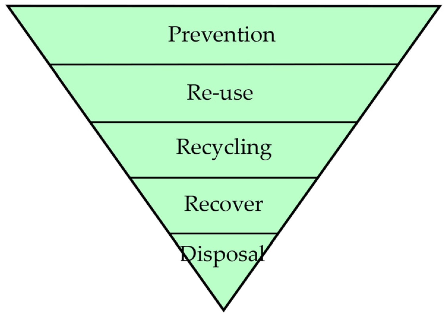
Figure 2.
Expected principal improvement of negative output over time with demolition vs. reuse of HCS. The figure is inspired by Naber [7].
Figure 2.
Expected principal improvement of negative output over time with demolition vs. reuse of HCS. The figure is inspired by Naber [7].

Figure 3.
Building layers with different life spans. The figure is inspired by Brand [11].
Figure 3.
Building layers with different life spans. The figure is inspired by Brand [11].

Figure 4.
Precast concrete reuse potential timeline. The research focus is highlighted with a red box.
Figure 4.
Precast concrete reuse potential timeline. The research focus is highlighted with a red box.

Figure 5.
Data from the five large Danish case buildings showing slab variations.

Figure 6.
HCS to wall connection details. Left: Span of HCS perpendicular to the wall. Right: Span of HCS parallel to the wall.
Figure 6.
HCS to wall connection details. Left: Span of HCS perpendicular to the wall. Right: Span of HCS parallel to the wall.

Figure 7.
Plan- and 3D-drawing of the structural system of the case study building with “extreme” geometry. Letters A to H and numbers 1 to 3 are modular lines.
Figure 7.
Plan- and 3D-drawing of the structural system of the case study building with “extreme” geometry. Letters A to H and numbers 1 to 3 are modular lines.

Figure 8.
Global and local model and stress distribution examples. A 2.4 m wide slab was used in the local model for easier modelling. Letters A to H are modular lines. The largest compression is blue and the smallest compression is red.
Figure 8.
Global and local model and stress distribution examples. A 2.4 m wide slab was used in the local model for easier modelling. Letters A to H are modular lines. The largest compression is blue and the smallest compression is red.

Figure 9.
Test setup without and with normal force applied. The width of the test specimens was 100 mm. The shear load was applied upwards.
Figure 9.
Test setup without and with normal force applied. The width of the test specimens was 100 mm. The shear load was applied upwards.

Figure 10.
Casting procedure: (A) Positioning of reinforcement in the mould; (B) Concrete cast in the bottom; (C) Form was flipped and mortar cast 24 h after the concrete.
Figure 10.
Casting procedure: (A) Positioning of reinforcement in the mould; (B) Concrete cast in the bottom; (C) Form was flipped and mortar cast 24 h after the concrete.

Figure 11.
Example of working curves for test specimens LC 50/50 without (top) and with (bottom) applied normal force of 10 kN.
Figure 11.
Example of working curves for test specimens LC 50/50 without (top) and with (bottom) applied normal force of 10 kN.

Figure 12.
DIC-monitoring output from measurements of surface deformations. The plot is of vertical deflections. On the right are graphs showing x- and y-deflections of specific surface points.
Figure 12.
DIC-monitoring output from measurements of surface deformations. The plot is of vertical deflections. On the right are graphs showing x- and y-deflections of specific surface points.

Figure 13.
Level 1 method for disassembly with direct removal by lifting with a mobile crane.

Figure 14.
(A) Jacks in the joint provide a force to slide an element horizontally. (B) The crane lifts the element.
Figure 14.
(A) Jacks in the joint provide a force to slide an element horizontally. (B) The crane lifts the element.

Figure 15.
(A) Example of 1st principal stresses shown locally at the thin side wall. (B) One possible solution to avoid punching failure of the side walls of HCSs.
Figure 15.
(A) Example of 1st principal stresses shown locally at the thin side wall. (B) One possible solution to avoid punching failure of the side walls of HCSs.


Table 1.
Tested combinations of parameters.
| Mortar Type | Normal Force | 0Y10 | 1Y10 | 2Y10 | Number of Representative Tests/Tests Performed [-] | Avg. Failure Load [kN] |
|---|---|---|---|---|---|---|
| Concrete and C100 | ● | 3/4 | 10.7 | |||
| ● | 3/4 | 32.3 | ||||
| ● | 4/4 | 40.5 | ||||
| ● | ● | 4/4 | 25.6 | |||
| ● | ● | 4/4 | 37.1 | |||
| ● | ● | 4/4 | 51.0 | |||
| Concrete and LC 50/50 | ● | 3/4 | 4.0 | |||
| ● | 3/4 | 6.0 | ||||
| ● | 4/4 | 8.5 | ||||
| ● | ● | 4/4 | 13.1 | |||
| ● | ● | 4/4 | 14.3 | |||
| ● | ● | 4/4 | 18.2 | |||
| Concrete and LC 35/65 | ● | 4/4 | 7.7 | |||
| ● | 4/4 | 9.9 | ||||
| ● | 4/4 | 17.1 | ||||
| ● | ● | 4/4 | 17.7 | |||
| ● | ● | 4/4 | 21.8 | |||
| ● | ● | 4/4 | 26.9 |
Table 2.
Case study building (from Figure 8) results of the largest compression and tension stress in different mortar types based on an Inventor model and critical wind load conditions.
Table 2.
Case study building (from Figure 8) results of the largest compression and tension stress in different mortar types based on an Inventor model and critical wind load conditions.
| Mortar Type | fc [MPa] | ft [MPa] | E [GPa] | G [GPa] 3 | σc Max [MPa] | σt Max [MPa] | dsystem Max [mm] |
|---|---|---|---|---|---|---|---|
| C 100 (tested) | 32 | 3.3 1 | 3.3 | 1.38 | 0.58 | 0.64 | 9.1 |
| LC 35/65 (tested) | 4.6 (2.0) 2 | 0.92 1 | 1.4 | 0.58 | 0.31 | 0.33 | 9.2 |
| LC 50/50 (tested) | 1.9 (0.9) 2 | 0.46 1 | 0.46 | 0.19 | 0.14 | 0.14 | 9.2 |
| C 100 4 | 20 | 2.0 | 30 | 12.5 | 1.7 | 1.71 | 8.9 |
| LC1 4 | 2.0 | 0.2–0.5 5 | 5 | 2.1 | 0.77 | 0.82 | 9.1 |
| LC2 4 | 10 | 1.0–2.5 5 | 10 | 4.2 | 1.11 | 1.13 | 9.0 |
1 Estimated as 62.5% of the flexural strength. 2 From the manufacturer of the mortar. 3 Calculated based on E. 4 From Gottfredsen and Nielsen [53]. 5 Estimated as 1/10 to 1/4 of fc.
Disclaimer/Publisher’s Note: The statements, opinions and data contained in all publications are solely those of the individual author(s) and contributor(s) and not of MDPI and/or the editor(s). MDPI and/or the editor(s) disclaim responsibility for any injury to people or property resulting from any ideas, methods, instructions or products referred to in the content. |
© 2023 by the author. Licensee MDPI, Basel, Switzerland. This article is an open access article distributed under the terms and conditions of the Creative Commons Attribution (CC BY) license (https://creativecommons.org/licenses/by/4.0/).
Share and Cite
MDPI and ACS Style
Halding, P.S. Design for Disassembly of Concrete Slabs with Mortar Joints. Buildings 2023, 13, 1957. https://doi.org/10.3390/buildings13081957
AMA Style
Halding PS. Design for Disassembly of Concrete Slabs with Mortar Joints. Buildings. 2023; 13(8):1957. https://doi.org/10.3390/buildings13081957
Chicago/Turabian StyleHalding, Philip Skov. 2023. "Design for Disassembly of Concrete Slabs with Mortar Joints" Buildings 13, no. 8: 1957. https://doi.org/10.3390/buildings13081957
Note that from the first issue of 2016, this journal uses article numbers instead of page numbers. See further details here.