Article

Numerical Simulation of Severe Damage to a Historical Masonry Building by Soil Settlement

1
Department of Civil Engineering, Karadeniz Technical University, 61080 Trabzon, Turkey
2
Department of Civil Engineering, Yıldız Technical University, 34220 Istanbul, Turkey
*
Author to whom correspondence should be addressed.
Buildings 2023, 13(8), 1973; https://doi.org/10.3390/buildings13081973
Submission received: 9 June 2023 / Revised: 16 June 2023 / Accepted: 26 June 2023 / Published: 2 August 2023
(This article belongs to the Section Building Structures)

Abstract

:
Historical masonry structures, which constitute an important part of the historical heritage, exhibit brittle behavior under tensile stresses due to earthquakes or soil movements/settlements. Therefore, they are sensitive to deformation. The soil–structure interaction problems play an important role in the damage to historical masonry structures. Different settlements, slips, and deformations in foundations causes damage to, and/or partial collapse the load-bearing walls. This study provides a numerical simulation of a historic masonry building on the north coast of Turkey, dating from 19th century, which suffered severe damage due to soil settlement by excavation activity near the building. FE models of the building with and without the soil–structure system were created to identify the damage to the building following soil settlement. The height of the soil domain (bounded as a fixed boundary condition) was accepted in the range of 1.5 m to 15 m. The damage propagation between the numerically obtained damage and the existing damage to the building was detailed and compared. In terms of displacement, the maximum vertical and horizontal displacement values reflecting the existing damage to the building were determined as 22 mm and 85 mm, respectively. The soil depth of 6 m was also considered acceptable for deciding the soil–structure interaction. For this, the sum of the rigid basement and the soil depth can be selected to be equal to the total height of the building participating in free vibration. It was concluded that the numerical procedure employed provided an effective representation of existing damage to a building due to soil settlement. Moreover, the procedure described can be adopted for possible collapse simulation.

1. Introduction

Many historical structures, such as castles, churches, temples, mosques, bridges, and cathedrals, which witness history and carry the traces of different civilizations, have been left to us as of our cultural heritage. Historical structures give identity to cities and provide information about the culture and life of societies. They are also often regarded as symbols of local identity and pride. Therefore, the protection of these masterpieces is an important responsibility. However, this part of our cultural heritage is seriously threatened over time by natural (climatic factors, earthquakes, floods, fires, ground settlement) and man-made (wars, vandalism) factors.
Many historical structures were erected with stone/brick and mortar using masonry methods, which was a common construction method in ancient times. Masonry structures consist of only a few materials, namely stone, brick, timber block, mortar, etc., and their structural behavior is quite complex. Climatic factors (extremely high or low temperatures, windstorms with high wind speeds, significant precipitation) can cause significant damage and deterioration in the integrity of historical structures or their elements. In masonry structures, there are secondary elements (tie beam, beam, etc.), which are built of wooden or metal materials. These parts may expand or shrink due to temperature differences, and this may result in cracks in the masonry elements. Natural stones can erode over time, and they can be seriously damaged due to the freeze–thaw effect. The rise in groundwater in the masonry walls and the capillary effect can also cause efflorescence in the masonry units, and this results in deterioration of the physical and chemical structure (Figure 1a) [1,2]. In addition, moisture has a negative effect on historical structures. It leads to bad smells, wetness on the walls, efflorescence, moss formations, and so on (Figure 1b) [3,4]. Walls close to the soil in a constantly humid environment can be exposed to moss formation with the effect of water rising from the foundation or environmental conditions formation (Figure 1c) [5,6]. Air pollution is another adverse effect for masonry elements. Stone surfaces that are not exposed to rainwater may turn black over time, and their authenticity and integrity may be affected by the crust cover formed (Figure 1d) [6,7]. Moreover, there are significant threats from a wide range of destructive actions such as earthquakes, floods, cyclones, vandalism, and soil settlement [4,8,9,10,11,12,13,14,15]. Some images of damage caused by some of these destructive actions are shown in Figure 2. In particular, one of the most serious threats to historical structures is earthquakes, which have many unknown parameters, such as occurrence location, time, magnitude, and so on.
Soil problems are among the main reasons for damage of historical masonry structures. The low strength or inhomogeneity of the soil domain is mostly caused due to cracks, rotations, and different settlements in these structures. It is known that if there is no very shallow foundation, the probability of settlement of the structure due to its weight is low. The main factors that cause settlement include: (i) the rise and fall in groundwater, (ii) change of the load system in structure or concentrated loading, (iii) excavation closely spaced to the structure, and (iv) dynamic actions. Masonry walls are highly vulnerable to support settlement. This is because of the low tensile strength and brittle behavior of the masonry wall. This leads to cracks, and partial or total collapse due to the soil problems in the masonry structures. The settlements can be categorized as uniform settlement, tilt, and non-uniform settlement. The uniform settlement is a situation where the foundation base of the structure sits parallel to its initial position and remains flat. If the foundation base does not remain parallel to its initial position while maintaining its plane state, this type of settlement is called a tilt. Also, the most problematic settlements are the non-uniform type settlements due to structural distortions [16]. Types of settlements are presented in Figure 3 as a schematic.
The stated factors are the main reasons for damage and/or partial collapse or collapse for the historical masonry structures. It should be noted that the adjacent soil excavation (excavation closely spaced to the structure) is a significant amount of reason for damage and/or partial collapse or collapse particularly of the historical masonry structures, which are quite vulnerable to any external effect. Therefore, the historical masonry structures must be also protected against the effect of human activities such as adjacent soil excavation for the future.
This study focused on the numerical simulation of a historic masonry building dating from the 19th century, on the north coast of Turkey. The soil excavation, which is near the building, caused different settlements, slips, and deformations at the foundation system, and this excavation gave rise to damage to the building. The building was out of use and the local government took the decision to undertake repairing and strengthening. The main goals of this study are developing a Finite Element (FE) model of the historical masonry building with the soil–structure interaction system, developing the soil settlement effect using the FE model, simulating the damage to the building due to soil settlements, and checking the damage level for the building.

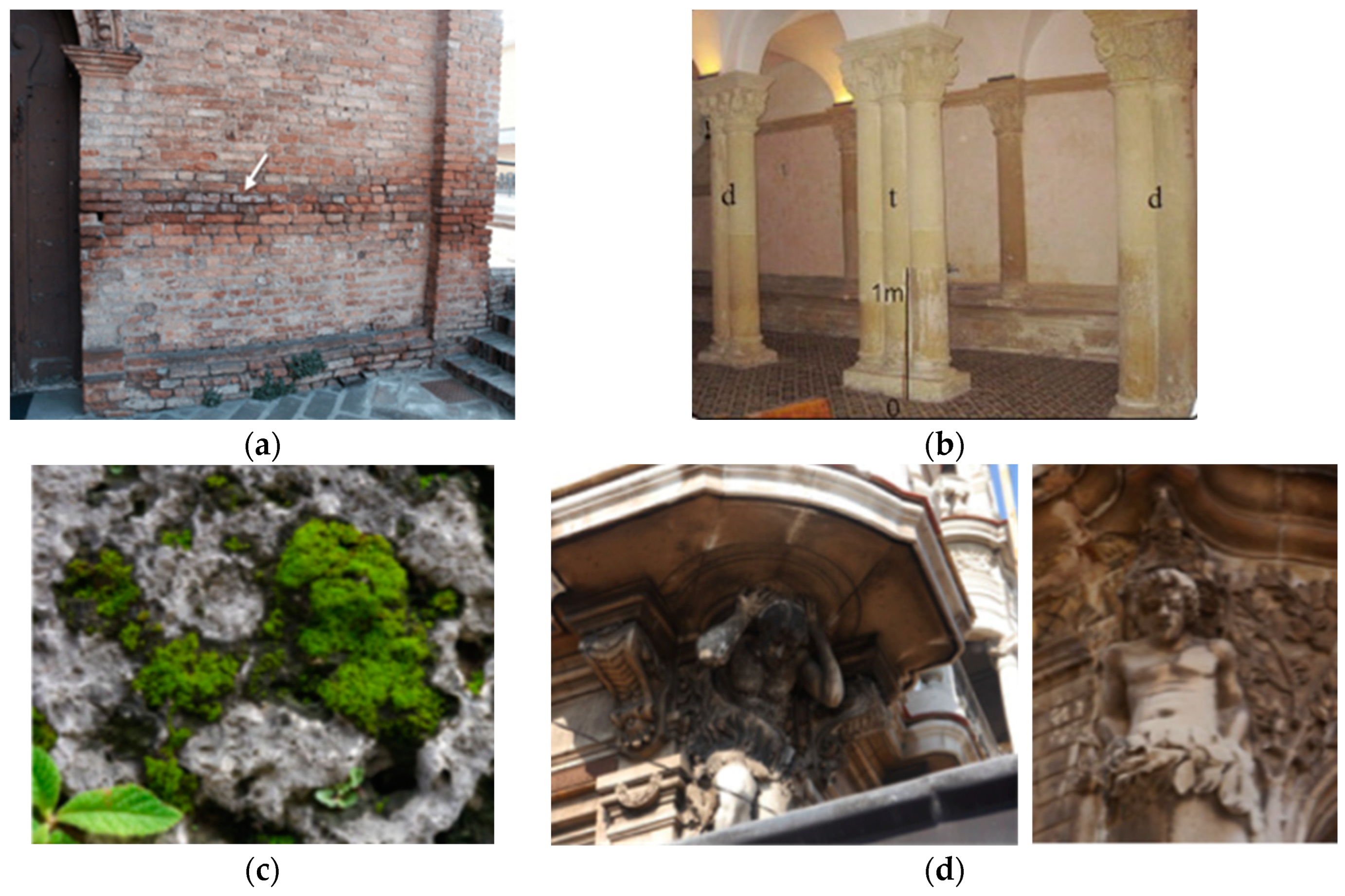
2. Historical Masonry Building

The historical masonry building in the province of Samsun (Figure 4), on the north coast of Turkey, dated back to the 1870s. The building was erected for different purposes. At the beginning of its history, the ground floor was used as an infirmary and the first floor was used as a dormitory. Late in the 20th century, it was being used as a school building. In the 1970s, a fire caused damage to the building, and then the damaged parts were rebuilt. The building has a rectangular plan (Figure 5) and consists of three storeys with a height of 2.64 m for the first, 4.26 m for the second, and 4.59 m for the third. The building was constructed according to the traditional masonry technique, using clay bricks. The inner walls at the third story were built using a timber frame system and plastered with timber laths. Also, the first storey (basement) was constructed by using rubble stone masonry and clay brick masonry walls. The thickness of the wall in the basement is approximately 0.7 m. The masonry walls at the upper parts vary in thickness from 0.45 to 0.60 m. The slab and roof systems were erected using timber elements. In 2020, it was decided to repair and strengthen the building due to damage to the masonry walls. The following were the reasons for the damage: the backyard ground of the building was excavated up to the foundation level for the parking facilities; the additional part at the left facade of the building was removed, and this area was excavated close to foundation level (Figure 6). These excavations caused the different soil settlements, slips, and deformations in the foundation system, and this resulted in damage to the building. Figure 7 shows the schematic views of the damage observed in the building. As can be seen, no damage to the walls at the right facade was propagated. The damage to the building occurred at the front, left, and back facades of the building. Figure 8 shows the cracks that occurred on the load-bearing walls of the building. It is well known that the most common sign of settlement crack is the cracks on the walls appearing in the form of diagonal or incline tension cracks. They are usually found around the edges of buildings and openings (doors and windows). As can be seen in Figure 8, the crack patterns indicate the presence of settlement beneath the building.
The results of settlements may affect the stability of the entire structure. Therefore, before starting any remediation of the structure, a detailed structural performance evaluation must be carried out. This should include in situ tests such as geotechnical exploration and numerical assessment such as FE analyses. FE analysis has a significant role to play in the analysis of possibilities for remediation (repairing and strengthening) and choosing the optimal method of structural behavior remediation. Using the FE analysis, the effects of settlement on structural performance can be obtained and evaluated. The soil–structure interaction should be accurately taken into account in this case to simulate the settlement that occurred.

3. Finite Element Model

The FE method is a practical tool to obtain the structural behavior of structures numerically. It is particularly useful when applied to determine the simulation of any unforeseen situation. This part presents the FE model of the historical building with and without the soil–structure system. The FE model of the building was developed using Abaqus 6.14 software [17]. The macro-modeling method, in which blocks, mortar, and block–mortar interface are smeared out in the continuum, was applied to represent the masonry walls. The blocks and mortar are modeled as a homogeneous and continuum material in the macro-modeling approach, and their mechanical properties are used in nonlinear finite element analysis. This approach is used to model relatively larger and more complicated masonry structures.
The soil–structure interaction can be categorized as the direct soil–structure interaction and the sub-structure approaches. The soil domain is represented using solid elements for the first (Figure 9a) while the soil domain is represented using a series of spring elements for the second (Figure 9b). During the numerical evaluation, the direct soil–structure interaction approach was employed. For this aim, the linear tetrahedron C3D4 finite element with four nodes was used. The dimensions of the soil were selected as 24 × 36 m for the transverse and longitudinal directions. The height of the soil domain (bounded as a fixed boundary condition) was in the range of 1.5 m to 15 m. As a boundary condition, the base/support was assumed as fixed. Figure 10 shows the FE model and soil-structure interaction system of the building.
There is no experimental study relevant to the material properties of the building due to legal protection. The material properties of the brick elements were considered based on a guideline called as Guide to the Management of Earthquake Risks of Historical Structures (GMERHS) [19]. Also, Concrete Damage Plasticity (CDP) model, which can be adapted to masonry structures, was employed to obtain the nonlinear material behavior of masonry units [20,21]. The stress–strain diagrams of the CDP model under uniaxial tension and compression are given in Figure 11.
Under uniaxial tension, the stress–strain response exhibits the linear elastic relationship until the value of the peak stress, σto, is reached. The peak tension stress corresponds to the onset of micro-cracking in the material. After the peak tension stress, the stress–strain response is defined by softening of the material. Under uniaxial compression, the stress–strain response exhibits the linear elastic relationship until the value of the initial yield, σco, is reached. In the plastic regime, the response is characteristically stated by stress hardening and then by strain softening beyond the ultimate stress, σcu. The stress–strain relations under uniaxial tension and compression loading are defined as follows:
σ t = ( 1 d t ) E 0 ( ε t ε t p l )
σ c = ( 1 d c ) E 0 ( ε c ε c p l )
where εc and εt are total strain in compressive and tension conditions, ε c p l and ε t p l are the equivalent plastic strain in compressive and tension conditions, E0 is the initial modulus of elasticity, dc and dt are compressive and tension damage parameters, respectively. Table 1, Table 2 and Table 3 present the linear and nonlinear material properties used in the FE model analyses.
The literature includes limited studies featuring use of a direct soil–structure interaction approach at the damage simulation due to soil settlement on historical structures [23]. There are some studies in the literature that focus on structural behavior of masonry structures taking into account the soil–structure interaction [24,25,26,27,28,29,30,31,32,33,34,35]. On the other hand, there are also studies that take into account the seismic effect and differential settlement effects for historical structures [36,37,38,39,40]. To our best knowledge, the investigation into the simulation of the damage to historical masonry structures due the soil settlement is rare. The contribution of this study may assist in alleviating this situation.

4. Numerical Evaluation

The soil domain was divided into grids to obtain the damage to the building following the soil settlement caused by the excavation activity near the building (Figure 12). The settlement effect was considered by defining weak soil properties for the back and left sides where damage to the building is cumulated. The intention was to capture the potential impact of soil settlement caused by the excavation on the structural integrity of the building. For this aim, the elasticity modulus and densities of soil domains were defined to be different using a trial-and-error procedure. The procedure was employed until the damage propagation on the building was obtained. It should be stated that, wherever possible, the soil properties were gradually increased from weak soil to hard soil to eliminate the settlement effect. The material properties of the soil domains, which are available in the literature, are also shown in Figure 12 [41,42,43]. As can be seen, the elasticity modulus values changed between 1.14 × 10⁹–5.68 × 10⁹ N/m2 while the density values changed between 1667–2064 kg/m3. Also, the Poisson ratio changed between 0.3–0.4.
The nonlinear analyses were employed to determine the soil settlement effect and the following damage to the building. For this aim, the rigid-base condition and soil–structure interaction systems were also employed. During the analyses, the dynamic explicit procedure was taken into account with the self-weight of the building taken as vertical load. At the end of the analyses, the displacement contour in the U2 (Y) and U3 (Z) directions for both conditions were obtained and presented in detail. Figure 13 shows the displacement contour diagram obtained from the rigid-base condition and the soil–structure interaction system. Moreover, Figure 14 presents the deformed and undeformed shapes and the change of displacements along the height of the building (U3 direction) for the soil–structure interaction system. As can be seen, the soil–structure interaction system was detailed under the different soil depths. This provided a determination of soil depth effects on the results obtained. From Figure 13 and Figure 14, it appears that the damage to the building was obtained at the facades where the soil was excavated. Also, the maximum displacement values increased with the increasing soil depth, as can be seen in Figure 14. Table 4 presents the comparison of the maximum displacement values. The maximum displacements were found to be 22 mm in the U1 direction and 85 mm in the U3 direction for the 9.0 m soil depth. Furthermore, it can be concluded that as the height of the weak soil increased, the deformation of the building also increased.
As can be seen in Figure 11, when the specimen is unloaded from any point on the strain softening curve of the stress–strain curves, the unloading response is weakened, and the elastic stiffness of the material can be understood as damaged. The damage of the elastic stiffness is defined by two damage variables, dt and dc. These are assumed to be functions of the plastic strains, temperature, and field variables as defined by following equations [17].
d t = d t ( ε t p l , θ , f i ) ; d c = d c ( ε c p l , θ , f i ) ;         0 d t 1 0 d c 1
The damage variables change in value from 0 to 1. The value of 0 represents the undamaged material, while the value of 1 represents the total loss of strength and complete deterioration of the material [17]. In the study, the tension damage factor, dt, was employed due to the nature of the masonry. Figure 15 shows the tension crack propagation of the building for different conditions. As shown in Figure 15, the building was almost undamaged at the rigid-base conditions. From Figure 15, it can be seen that serious damage was sustained by the masonry walls in the case of the soil–structure interaction system. Table 5 presents the number of damaged masonry elements by all masonry elements. One can see from this table that the highest percentage of damaged elements was obtained for the 6 m soil depth. It should be stated that the crack propagation on the masonry walls was similar where the soil heights were 6 and 9 m. This means that the soil depth of 6 m is acceptable to take into account the soil–structure interaction system. It should be noted that the soil depth employed can be determined in accordance with the total building height. Here the sum of the rigid basement and soil depth can be selected to be equal to the total height of the building participating in free vibration.
The damages to masonry walls cumulated on the front, left, and back facades of the building. This was similar to in situ damages to building (refer to Figure 15). As can be seen, the cracks on the walls appeared in the form of diagonal and incline tension cracks. Also, some cracks occurred along the horizontal bed joints. The damages occurred around the openings. Figure 16 shows a comparison of damage propagation obtained from the numerical model and existing damage propagation. Figure 16 indicated that there are definite similarities between the two.

5. Conclusions

This study presents the numerical simulation of a historical building that suffered severe damage due to the soil settlement by the excavation activity near the building. The intention is to evaluate the potential damage impact of soil settlement caused by the excavation on the structural integrity of the building. For this aim, FE models of the building were constituted with and without the soil domain. The nonlinear analyses were considered in the analyses for the different soil depths, which were accepted in the range of 1.5 m to 15 m. The following conclusions were drawn from the study:
  • The direct soil–structure interaction approach provided an effective representation of existing damage to the building due to the soil settlement. But the rigid-base condition lagged the soil–structure interaction approach in the representation of existing damage to the building.
  • The soil depth was selected as 1.5 m, 6 m, and 9 m. The maximum displacement values increased with the increasing soil depth. The maximum vertical and horizontal displacement values were obtained as 22 mm and 85 mm. These caused the diagonal and incline tension cracks, which are similar to existing damage propagation on the building.
  • The highest damage level was obtained as 4.77% for the soil depth of 6 m. The crack propagation was almost the same for the 6 m and 9 m soil depths. This indicated that the soil depth of 6 m is acceptable to take into consideration the soil–structure interaction. For the effective soil depth, the sum of rigid basement and soil depth can be selected to be equal to total height of the building participating in free vibration.
Historical masonry structures are a significant part of cultural heritage. Due to the nature of them, they are vulnerable to tension forces. It is clearly known that the factor caused by tension forces must be eliminated or limited. The soil settlement is among one of the reasons for such forces. Unfortunately, the soil excavation close to the building frequently causes soil settlement and subsequent damage to building. This results in the deterioration of structural stability. For this reason, before starting any intervention, on-site detailed structural evaluation of buildings must be practiced for the historical masonry buildings. The FE model with the soil–structure interaction system proved effective in simulating soil settlement and subsequent damage to building occurred. Moreover, the FE model obtained can also use a condition evaluation of the building after the proposed intervention such as repairing or strengthening.

Author Contributions

Conceptualization, A.C.A. and E.E.A.; methodology, B.S.; software, E.E.A. and A.F.G.; investigation, A.C.A. and B.S.; writing—original draft preparation, E.E.A. and A.F.G.; writing—review and editing, A.C.A., M.G. and B.S.; visualization, E.E.A. and A.F.G.; supervision, A.C.A. and B.S. All authors have read and agreed to the published version of the manuscript.

Funding

This research received no external funding.

Data Availability Statement

The data presented in this study are available on request from the corresponding author.

Conflicts of Interest

We wish to confirm that there are no known conflict of interest associated with this publication, and there has been no significant financial support for this work that could have influenced its outcome.

References

  1. Giaccone, D.; Santamaria, U.; Corradi, M. An experimental study on the effect of water on historic brickwork masonry. Haritage 2020, 3, 29–46. [Google Scholar] [CrossRef] [Green Version]
  2. Franzoni, E. Rising damp removal from historical masonries: A still open challenge. Constr. Build. Mater. 2014, 54, 123–136. [Google Scholar] [CrossRef]
  3. D’Agostino, D. Moisture dynamics in an historical masonry structure: The Cathedral of Lecce (South Italy). Build. Environ. 2013, 63, 122–133. [Google Scholar] [CrossRef]
  4. Döndüren, M.S.; Şişik, Ö.; Demiröz, A. Types of damage in historical buildings. Selçuk Univ. J. Soc. Tech. Res. 2017, 13, 45–58. (In English) [Google Scholar]
  5. Erkal, A.; D’Ayala, D.; Stephenson, V. Evaluation of environmental impact on historical stone masonry through on-site monitoring appraisal. Q. J. Eng. Geol. Hydrogeol. 2013, 46, 449–458. [Google Scholar] [CrossRef]
  6. Hernández, A. Impact of environmental pollution in the historical buildings of Havana, Cuba. Effect of future climate change. Rev. Ing. Constr. 2018, 33, 219–228. [Google Scholar] [CrossRef] [Green Version]
  7. Gaylarde, C.C. Influence of environment on microbial colonization of historic stone buildings with emphasis on cyanobacteria. Heritage 2020, 3, 1469–1483. [Google Scholar] [CrossRef]
  8. Cancino, C.; Farneth, S.; Garnier, P.; Vargas Neumann, J.; Webster, F. Damage Assessment of Historic Earthen Buildings after the August 15, 2007 Pisco, Peru Earthquake; The Getty Conservation Institute: Los Angeles, CA, USA, 2009. [Google Scholar]
  9. FHB. English Heritage: Flooding and Historic Buildings; English Heritage Publishing: Swindon, UK, 2015. [Google Scholar]
  10. Doğangün, A.; Acar, R.; Livaoğlu, R.; Tuluk, Ö.İ. Performance of masonry minarets against earthquakes and winds in Turkey. In Proceedings of the 1st International Conference on Restoration of Heritage Masonry Structures, Cairo, Egypt, 24–27 April 2006. [Google Scholar]
  11. Brandonisio, G.; Lucibello, G.; Mele, E.; De Luca, A. Damage and performance evaluation of masonry churches in the 2009 L’Aquila earthquake. Eng. Fail. Anal. 2013, 34, 693–714. [Google Scholar] [CrossRef]
  12. Indirli, M.; SKouris, L.A.; Formisano, A.; Borg, R.P.; Mazzolani, F.M. Seismic damage assessment of unreinforced masonry structures after The Abruzzo 2009 earthquake: The case study of the historical centers of L’Aquila and Castelvecchio Subequo. Int. J. Archit. Herit. 2013, 7, 536–578. [Google Scholar] [CrossRef]
  13. Ciocci, M.P.; Sharma, S.; Lourenço, P.B. Engineering simulations of a super-complex cultural heritage building: Ica Cathedral in Peru. Meccanica 2018, 53, 1931–1958. [Google Scholar] [CrossRef] [Green Version]
  14. Mosoarca, M.; Keller, A.L.; Bocan, C. Failure analysis of church towers and roof structures due to high wind velocities. Eng. Fail. Anal. 2019, 100, 76–87. [Google Scholar] [CrossRef]
  15. Penna, A.; Calderini, C.; Sorrentino, L.; Carocci, C.F.; Cescatti, E.; Sisti, R.; Prota, A. Damage to churches in the 2016 central Italy earthquakes. Bull. Earthq. Eng. 2019, 17, 5763–5790. [Google Scholar] [CrossRef]
  16. Al-Taie, E.; Al-Ansari, N.; Knutsson, S. Estimation of settlement under shallow foundation for different regions in Iraq using safe software. Engineering 2015, 7, 379–386. [Google Scholar] [CrossRef]
  17. Abaqus, 6.14; Dassault Systémes Simulia Corp: Providence, RI, USA, 2014.
  18. Li, M.; Lu, X.; Lu, X.; Ye, L. Influence of soil structure interaction on seismic collapse resistance of super-tall buildings. J. Rock Mech. Geotech. Eng. 2014, 6, 477–485. [Google Scholar] [CrossRef]
  19. GMERHS. Guide to the Management of Earthquake Risks of Historical Structures; General Directorate for Foundations: Ankara, Turkey, 2017.
  20. Lubliner, J.; Oliver, J.; Oller, S.; Oñate, E. A plastic-damage model for concrete. Int. J. Solids Struct. 1989, 25, 299–326. [Google Scholar] [CrossRef]
  21. Lee, J.; Fenves, G.L. A plastic-damage concrete model for earthquake analysis of dams. Earthq. Eng. Struct. Dyn. 1998, 27, 937–956. [Google Scholar] [CrossRef]
  22. Tiberti, S.; Acito, M.; Milani, G. Comprehensive FE numerical insight into Finale Emilia Castle behavior under 2012 Emilia Romagna seismic sequence: Damage causes and seismic vulnerability mitigation hypothesis. Eng. Struct. 2016, 117, 397–421. [Google Scholar] [CrossRef]
  23. Kujawa, M.; Lubowiecka, I.; Szymczak, C. Finite element modelling of a historic church structure in the context of a masonry damage analysis. Eng. Fail. Anal. 2020, 107, 104233. [Google Scholar] [CrossRef]
  24. Wolf, J. Dynamic Soil-Structure Interaction; Prentice Hall: Englewood Clif, NJ, USA, 1985. [Google Scholar]
  25. Gazetas, G. Formulas and charts for impedances of surface and embedded foundations. J. Geotech. Eng. 1991, 117, 1363–1381. [Google Scholar] [CrossRef]
  26. Mylonakis, G.; Nikolaou, S.; Gazetas, G. Footings under seismic loading: Analysis and design issues with emphasis on bridge foundations. Soil Dyn. Earthq. Eng. 2006, 26, 824–853. [Google Scholar] [CrossRef]
  27. NEHRP. Soil-Structure Interaction for Building Structures; NIST GCR 12-917-21; U. S. Department of Commerce National Institute of Standards and Technology: Gaithersburg, MD, USA, 2012.
  28. Milani, G.; Valente, M. Failure analysis of seven masonry churches severely damaged during the 2012 Emilia-Romagna (Italy) earthquake: Non-linear dynamic analyses vs conventional static approaches. Eng. Fail. Anal. 2015, 54, 13–56. [Google Scholar] [CrossRef]
  29. Valente, M.; Milani, G. Non-linear dynamic and static analyses on eight historical masonry towers in the North-East of Italy. Eng. Struct. 2016, 114, 241–270. [Google Scholar] [CrossRef]
  30. Llopis-Pulido, V.; Durá, A.A.; Fenollosa, E.; Martínez, A. Analysis of the structural behavior of the historical constructions: Seismic evaluation of the Cathedral of Valencia (Spain). Int. J. Archit. Herit. 2019, 13, 205–214. [Google Scholar] [CrossRef]
  31. Lazizi, A.; Tahghighi, H. Seismic Response Evaluation of Kashan Historical Bazaar Structure Including Soil-Structure Interaction. J. Seismol. Earthq. Eng. 2019, 21, 77–93. [Google Scholar] [CrossRef]
  32. Anastasios, D.; Verstrynge, E.; Szekér, P.; Heirman, G.; Bejarano-Urrego, E.; Giardina, G.; Van Balen, K. Numerical modeling of a church nave wall subjected to differential settlements: Soil-structure interaction, time-dependence and sensitivity analysis. Int. J. Archit. Herit. 2020, 14, 1221–1238. [Google Scholar] [CrossRef]
  33. Altıok, T.Y.; Demir, A. Collapse mechanism estimation of a historical masonry minaret considered soil-structure interaction. Earthq. Struct. 2021, 21, 161–172. [Google Scholar] [CrossRef]
  34. Longo, M.; Sousamli, M.; Korswagen, P.A.; Van Staalduinen, P.; Rots, J.G. Sub-structure-based ‘three-tiered’ finite element approach to soil-masonry-wall interaction for light seismic motion. Eng. Struct. 2021, 245, 112847. [Google Scholar] [CrossRef]
  35. Brunelli, A.; De Silva, F.; Piro, A.; Parisi, F.; Sica, S.; Silvestri, F.; Cattari, S. Numerical simulation of the seismic response and soil–structure interaction for a monitored masonry school building damaged by the 2016 Central Italy earthquake. Bull. Earthq. Eng. 2021, 19, 181–1211. [Google Scholar] [CrossRef]
  36. Mallardo, V.; Malvezzi, R.; Milani, E.; Milani, G. Seismic vulnerability of historical masonry buildings: A case study in Ferrara. Eng. Struct. 2008, 30, 2223–2241. [Google Scholar] [CrossRef]
  37. Casalegno, C.; Cecchi, A.; Reccia, E.; Russo, S. Heterogeneous and contınuous models: Comparatıve analysıs of masonry wall subjected to dıfferentıal settlements. Compos. Mech. Comput. Appl. Int. J. 2013, 4, 187–207. [Google Scholar] [CrossRef]
  38. Shehu, R. Preliminary assessment of the seismic vulnerability of three inclined bell-towers in ferrara, Italy. Int. J. Archit. Herit. 2020, 16, 485–517. [Google Scholar] [CrossRef]
  39. Ou, W.; Chen, X.; Chan, A.; Cheng, Y.; Wang, H. Fdem simulation on the failure behavior of historic masonry heritages subjected to differential settlement. Buildings 2022, 12, 1592. [Google Scholar] [CrossRef]
  40. Angjeliu, G.; Bruggi, M.; Taliercio, A. Implementation of an elastic no-tension material model in a sequentially linear analysis framework. Finite Elem. I Anal. Des. 2023, 216, 103891. [Google Scholar] [CrossRef]
  41. Altıok, T.Y.; Demir, A. Seismic damage assessment of a historical masonry minaret considering soil-structure interaction. J. Struct. Eng. Appl. Mech. 2021, 4, 196–212. [Google Scholar] [CrossRef]
  42. Hökelekli, E.; Al-Helwani, A. Effect of soil properties on the seismic damage assessment of historical masonry minaret-soil interaction systems. Struct. Des. Tall Spec. Build. 2019, 29, e1694. [Google Scholar] [CrossRef]
  43. Kramer, S. Geotechnical Earthquake Engineering; Prentice Hall: Upper Saddle River, NJ, USA, 1996. [Google Scholar]
Figure 1. Views of damage to historical masonry structures due to (a) capillarity [2], (b) moisture [3], (c) moss formation [6], and (d) black crust action [6].
Buildings 13 01973 g001
Figure 2. View of damage to historical structures due to (a) August 15, 2007 Pisco, Peru Earthquake [8], (b) 6 February 2023 Kahramanmaraş Earthquake, and (c) floods [9].
Buildings 13 01973 g002aBuildings 13 01973 g002b
Figure 3. Types of settlements: (a) uniform settlement, (b) tilt, and (c) non-uniform settlement.
Buildings 13 01973 g003
Figure 4. Some views of the building: (a) before damage to the building and (b) restoration and during the repairing and strengthening.
Buildings 13 01973 g004aBuildings 13 01973 g004b
Figure 5. Views of the drawings: (a) plan views, (b) front facade, (c) left facade, (d) right facade, and (e) back facade.
Buildings 13 01973 g005
Figure 6. Views of the excavated areas near the building.
Buildings 13 01973 g006
Figure 7. Schematic views of the damage found in the building investigated: (a) front facade, (b) left facade, (c) right facade, and (d) back facade.
Buildings 13 01973 g007
Figure 8. Views of the damage to the building: (a) front facade, (b) left facade, (c) back facade, and (d) some interior parts of the building (The red and yellow squares were used to show the location of the actual damages on the structure).
Buildings 13 01973 g008aBuildings 13 01973 g008b
Figure 9. Schematic views of soil–structure interaction: (a) direct soil–structure interaction approach, and (b) sub-structure approach [18].
Buildings 13 01973 g009
Figure 10. Views of the FE model of (a) rigid-base condition and (b) soil-structure system of the building.
Buildings 13 01973 g010
Figure 11. Stress–strain diagrams of the CDP model: (a) uniaxial tension and (b) uniaxial compression.
Buildings 13 01973 g011
Figure 12. The soil domain divided into grids and its material properties are included in the FE model.
Buildings 13 01973 g012
Figure 13. Displacements in U2 and U3 directions for rigid-base system and soil–structure interaction systems with different soil depths.
Buildings 13 01973 g013
Figure 14. (a) Deformed and undeformed shapes and (b) the change of displacements along the height of the building at the U3 direction for the soil–structure interaction system for the different soil depths.
Buildings 13 01973 g014
Figure 15. Tension damage level of the rigid-base and soil–structure interaction systems for the different soil depths. (a) left facade, (b) front facade, and (c) back facade.
Buildings 13 01973 g015
Figure 16. A comparison of the damage propagation for the numerical and existing damage (with yellow lines).
Buildings 13 01973 g016
Table 1. The linear elastic material parameters included in the FE model [19].
ElementElasticity Modulus (N/m2)Poisson Ratio (-)Density (kg/m3)
Masonry1.8 × 1090.21800
Table 2. Mechanical parameters of masonry for the CDP model [22].
Dilation AngleEccentricityfb0/fc0KcViscosity Parameter
100.11.160.6660.002
Table 3. Stress–inelastic strain values and damage parameters of the masonry [22].
CompressionTensionTensile Damage Parameters
σ (MPa)εplσ (MPa)εpldt ε t p l
1.2200.04000
0.950.0050.00050.0030.950.003
0.950.0010.00050.100
0.80.100--
Table 4. Comparison of the maximum displacement values.
SystemMaximum Displacement (m)
U1U3
Rigid-base 0.000790.0034
Diff. (%)94.7393.06
Soil–structure system/H = 1.5 m0.0150.049
Diff. (%)21.0540.24
Soil–structure system/H = 6.0 m0.0190.082
Diff. (%)13.643.53
Soil–structure system/H = 9.0 m0.0220.085
diff. were calculated between in each lines for the maximum displacement values obtained in the U1 and U3 directions.
Table 5. The number of damaged elements and corresponding damaged percentage.
SystemNumber of Damaged Elements* Percentage (%)
Rigid-base0.00.00
Soil–structure interactionH = 1.5 m18094.18
H = 6.0 m20674.77
H = 9.0 m19414.48
* Percentage. gives the ratio of damaged elements to total number of elements (43,317).
Disclaimer/Publisher’s Note: The statements, opinions and data contained in all publications are solely those of the individual author(s) and contributor(s) and not of MDPI and/or the editor(s). MDPI and/or the editor(s) disclaim responsibility for any injury to people or property resulting from any ideas, methods, instructions or products referred to in the content.

