
Experimental and Theoretical Analysis of Flexural Properties of Mortar Beam Reinforced with Coated Carbon-Fiber Textile
 ,
,  ,
,
Abstract
:1. Introduction
2. Experiment
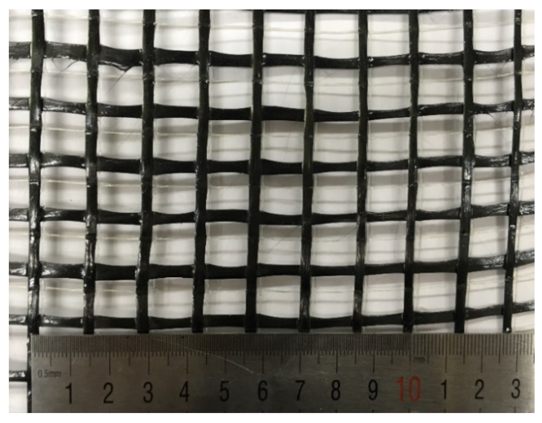
2.1. Materials
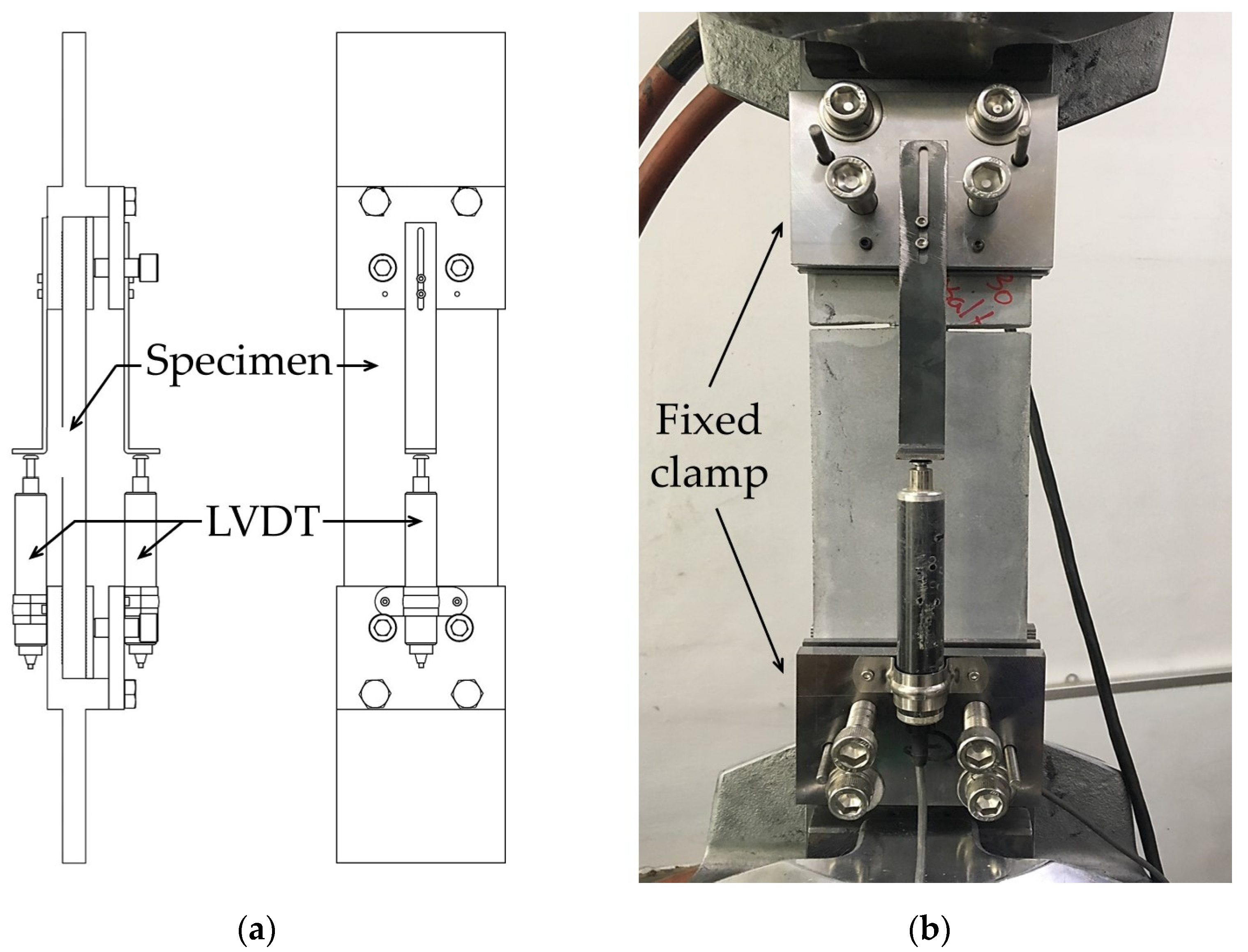
2.2. Direct Pull-Out Test
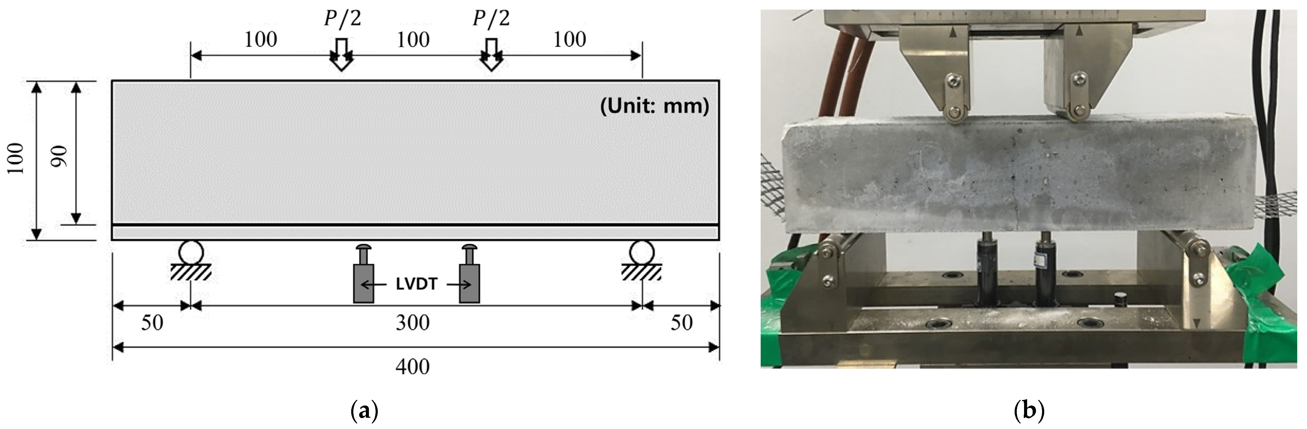
2.3. Four-Point Bending Test
3. Experimental Results and Discussion
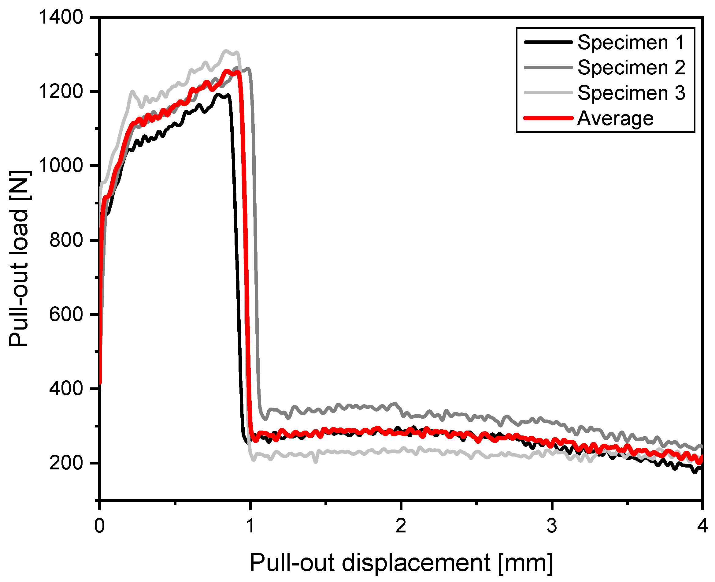
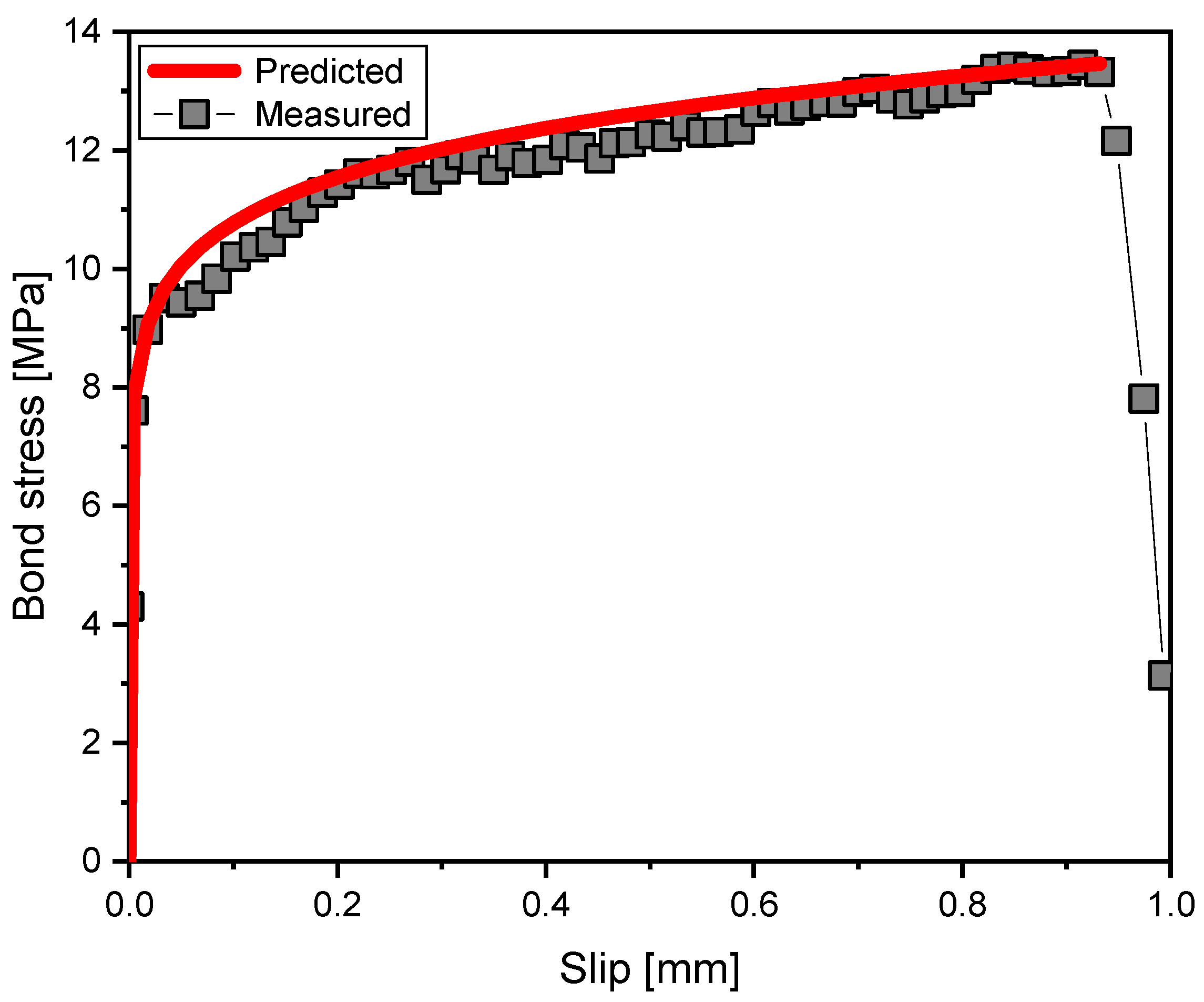
3.1. Pull-Out of Textile Reinforcement in Cement Composites
3.2. Flexural Load–Displacement Response of the TRM
4. Analysis for the Flexural Behavior
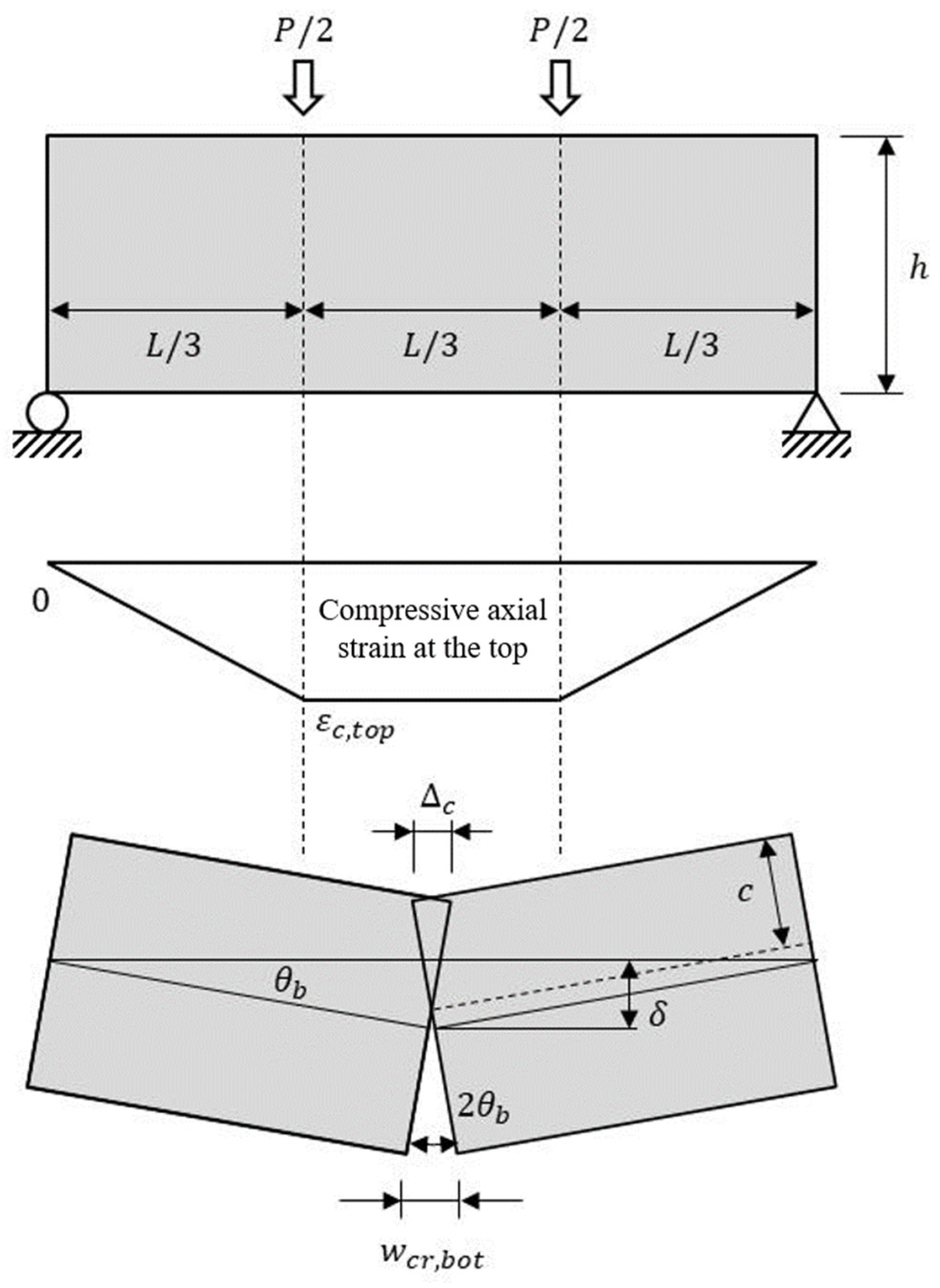
4.1. Idealization of the Flexural Behavior
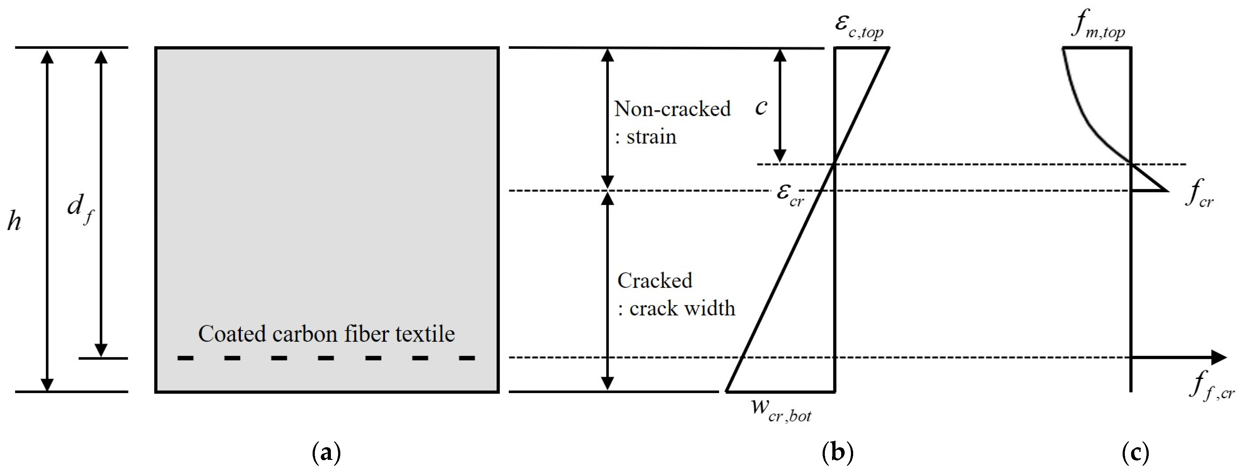
4.2. Stress Distribution and Internal Moment at the Critical Section
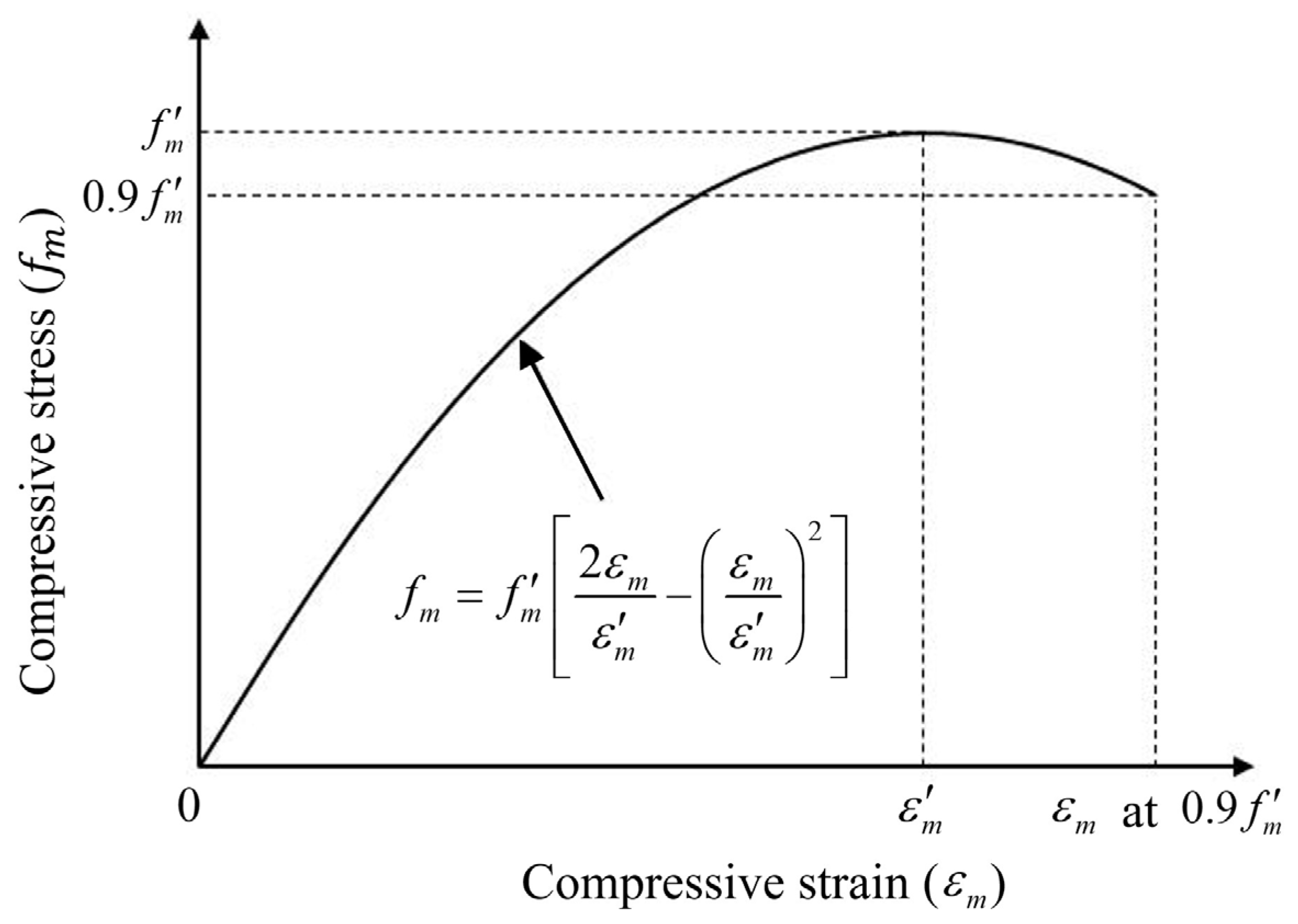
4.3. Constitutive Relations
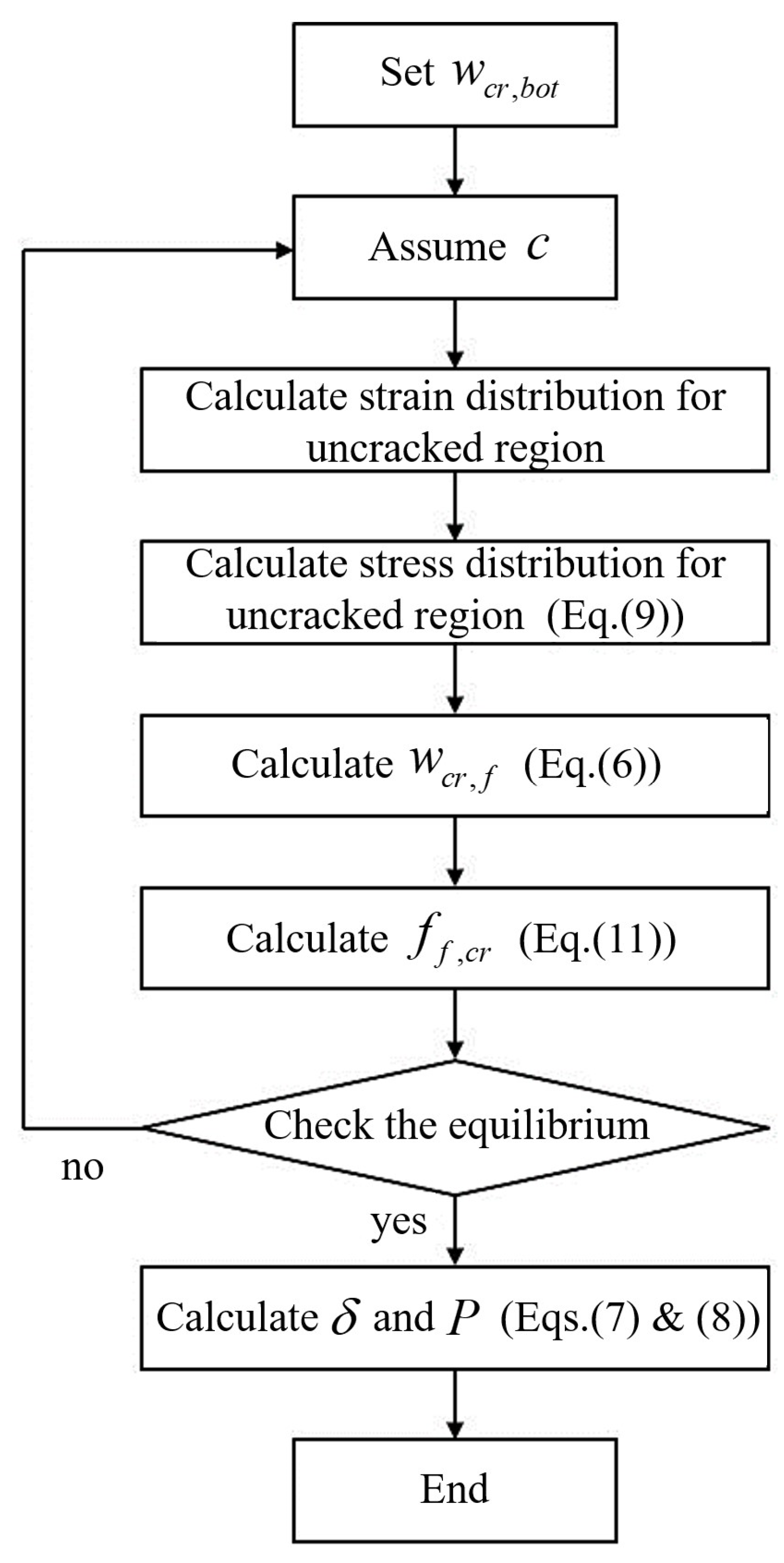
4.4. Analysis Algorithm
4.5. Comparison with the Test Results
5. Conclusions and Discussion
- The bond stress–slip behavior of coated carbon-fiber textile embedded in the cementitious materials was investigated through a double-sided unsymmetrical pull-out test. Test results demonstrated that the adhesion bond in the textile–cement matrix interfacial zone was initially dominant, but the pull-out behavior came to increasingly rely on the bond strength between the textile and the cement matrix as the pull-out displacement increased. The mean maximum bond stress was approximately 13.44 MPa when slip reached approximately 0.92 mm.
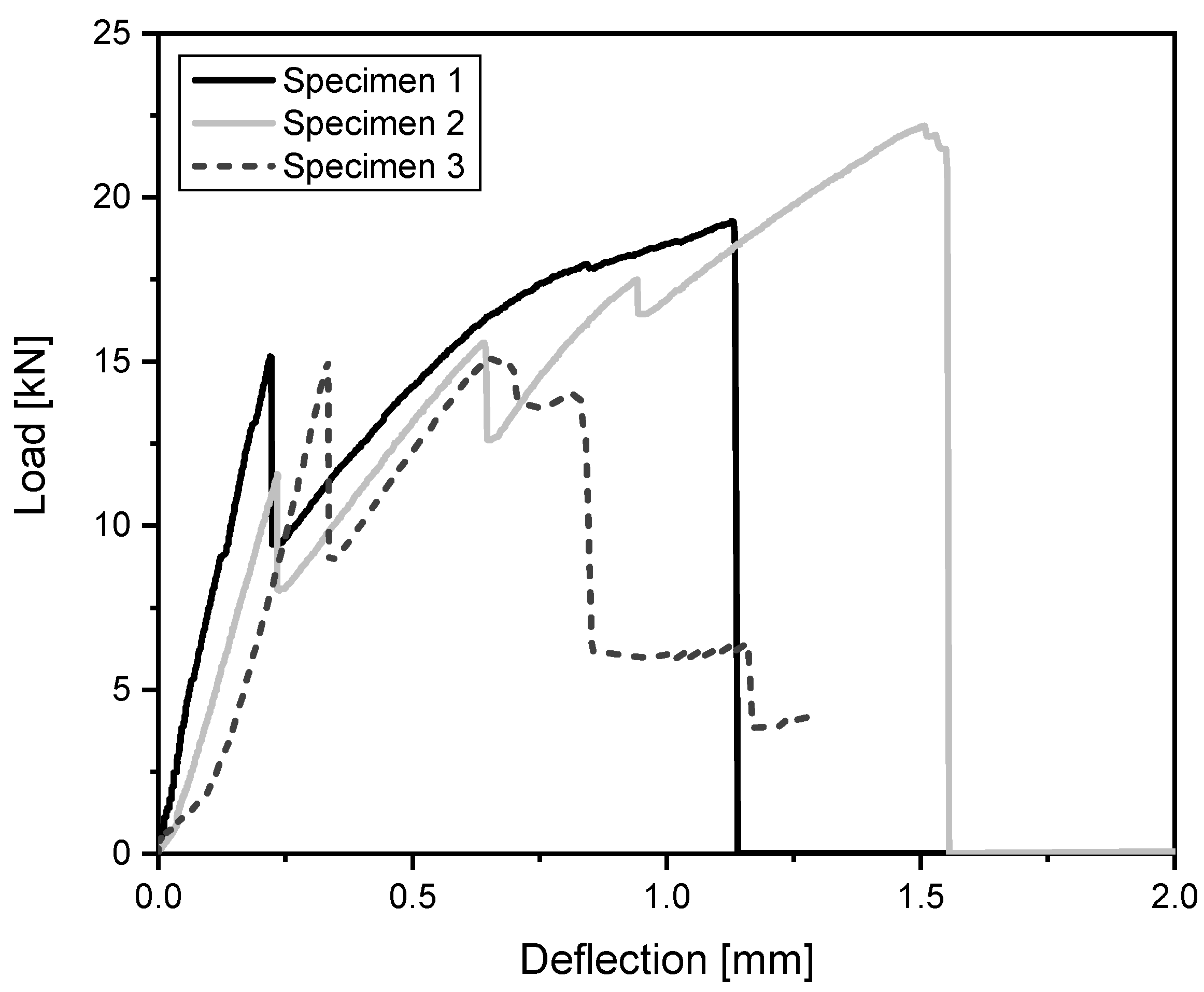
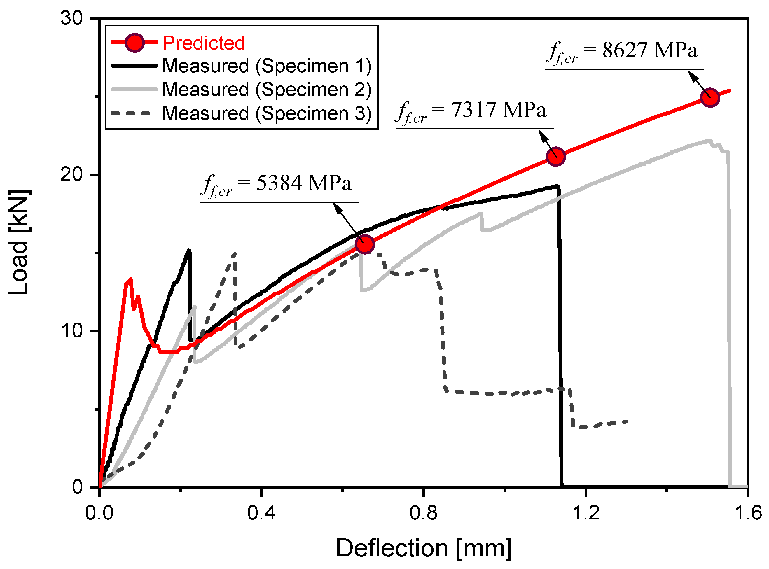
- In the four-point bending test for the TRM beam, as the load increased, the dominant flexural crack gradually developed in the bottom-center of the beam specimen. Finally, brittle fracture occurred due to the rupture of the coated carbon-fiber textile exposed to the crack. The load temporarily decreased immediately after cracking, but the load gradually increased until fracture, because the ductility of the TRM beam was secured by the bond behavior of the textile in the tensile zone. The mean ultimate strength of the TRM beam increased by approximately 36% compared to the mean first-crack strength. This confirmed that the textile used was effective as a reinforcement for improving the tensile performance of cementitious materials after cracking.
- A theoretical analysis method capable of predicting the flexural behavior of the TRM beam was established by idealizing the failure mode based on the actual bond behavior of textile reinforcement in cementitious materials. A comparison of measured and predicted results confirmed that the proposed analysis method can effectively predict the flexural behavior of the cracked TRM beam.
Author Contributions
Funding
Data Availability Statement
Conflicts of Interest
References
- ACI Committee. Building Code Requirements for Structural Concrete (ACI 318-08) and Commentary; American Concrete Institute: Farmington Hills, MI, USA, 2008. [Google Scholar]
- BS EN 1992-1-1:2004; Eurocode 2: Design of Concrete Structures. General Rules and Rules for Buildings. British Standards Institute: London, UK, 2004.
- Duprat, F. Reliability of RC Beams Under Chloride-Ingress. Constr. Build. Mater. 2007, 21, 1605–1616. [Google Scholar] [CrossRef]
- Mehta, P.; Monteiro, P. Concrete: Microstructure, Properties and Materials, 3rd ed.; McGraw Hill: New York, NY, USA, 2006. [Google Scholar]
- Neville, A.M. Properties of Concrete; Wiley: New York, NY, USA, 1996. [Google Scholar]
- Yoon, S.; Wang, K.; Weiss, W.J.; Shah, S.P. Interaction between loading, corrosion, and serviceability of reinforced concrete. ACI Mater. J. 2000, 97, 637–644. [Google Scholar]
- Triantafyllou, G.G.; Rousakis, T.C.; Karabinis, A.I. Analytical assessment of the bearing capacity of RC beams with corroded steel bars beyond concrete cover cracking. Compos. Part B Eng. 2017, 119, 132–140. [Google Scholar] [CrossRef]
- Zollo, R.F. Fiber-reinforced concrete: An overview after 30 years of development. Cem. Conc. Compos. 1997, 19, 107–122. [Google Scholar] [CrossRef]
- Yoo, D.-Y.; Banthia, N. Impact resistance of fiber-reinforced concrete—A review. Cem. Conc. Compos. 2019, 104, 103389. [Google Scholar] [CrossRef]
- Hegger, J.; Voss, S. Investigations on the Bearing Behaviour and Application Potential of Textile Reinforced Concrete. Eng. Struct. 2008, 30, 2050–2056. [Google Scholar] [CrossRef]
- Koutas, L.N.; Tetta, Z.; Bournas, D.A.; Triantafillou, T.C. Strengthening of Concrete Structures with Textile Reinforced Mortars: State-of-the-Art Review. J. Compos. Constr. 2019, 23, 03118001. [Google Scholar] [CrossRef]
- Mercuri, M.; Vailati, M.; Gregori, A. Lime-based mortar reinforced with randomly oriented polyvinyl-alcohol (PVA) fibers for strengthening historical masonry structures. Dev. Built. Environ. 2023, 14, 100152. [Google Scholar] [CrossRef]
- Vailati, M.; Mercuri, M.; Angiolilli, M.; Gregori, A. Natural-fibrous lime-based mortar for the rapid retrofitting of heritage masonry buildings. Fibers 2021, 9, 68. [Google Scholar] [CrossRef]
- Angiolilli, M.; Gregori, A.; Vailati, M. Lime-based mortar reinforced by randomly oriented short fibers for the retrofitting of the historical masonry structure. Materials 2020, 13, 3462. [Google Scholar] [CrossRef]
- Thong, C.C.; Teo, D.C.L.; Ng, C.K. Application of polyvinyl alcohol (PVA) in cement-based composite materials: A review of its engineering properties and microstructure behavior. Constr. Build. Mater. 2016, 107, 172–180. [Google Scholar] [CrossRef]
- Ticoalu, A.; Aravinthan, T.; Cardona, F. A review of current development in natural fiber composites for structural and infrastructure applications. In Proceedings of the Southern Region Engineering Conference (SREC 2010), Toowoomba, Australia, 10–12 November 2010; pp. 113–117. [Google Scholar]
- Shams, A.; Horstmann, M.; Hegger, J. Experimental investigations on Textile-Reinforced Concrete (TRC) sandwich sections. Compos. Struct. 2014, 118, 643–653. [Google Scholar] [CrossRef]
- Portal, N.W.; Flansbjer, M.; Johannesson, P.; Malaga, K.; Lundgren, K. Tensile behaviour of textile reinforcement under accelerated ageing conditions. J. Build. Eng. 2015, 5, 57–66. [Google Scholar] [CrossRef]
- Lee, S.-C.; Oh, J.-H.; Cho, J.-Y. Fiber orientation factor on rectangular cross-section in concrete members. Int. J. Eng. Technol. 2015, 7, 470–473. [Google Scholar]
- Lee, S.-C.; Oh, J.-H.; Cho, J.-Y. Fiber efficiency in SFRC members subjected to uniaxial tension. Constr. Build. Mater. 2016, 113, 479–487. [Google Scholar] [CrossRef]
- Portal, N.W.; Perez, I.F.; Thrane, L.N.; Lundgren, K. Pull-out of textile reinforcement in concrete. Constr. Build. Mater. 2014, 71, 63–71. [Google Scholar] [CrossRef]
- Naser, M.Z.; Hawileh, R.A.; Abdalla, J.A. Fiber-reinforced polymer composites in strengthening reinforced concrete structures: A critical review. Eng. Struct. 2019, 198, 109542. [Google Scholar] [CrossRef]
- Bielak, J.; Li, Y.; Hegger, J.; Chudoba, R. Characterization procedure for bond, anchorage and strain-hardening behavior of textile-reinforced cementitious composites. In Proceedings of the 18th International Conference on Experimental Mechanics (ICEM 2018), Brussels, Belgium, 1–5 July 2018; p. 395. [Google Scholar]
- Goliath, K.B.; Cardoso, D.C.; Silva, F.D.A. Flexural behavior of carbon-textile-reinforced concrete I-section beams. Compos. Struct. 2021, 260, 113540. [Google Scholar] [CrossRef]
- Portal, N.W.; Lundgren, K.; Walter, A.M.; Frederiksen, J.O.; Thrane, L.N. Numerical modelling of textile reinforced concrete. In Proceedings of the 8th Intermational Conference on Fracture Mechanics of Concrete and Concrete Structures (FraMCoS 2013), Toledo, Spain, 11–14 March 2013; pp. 886–897. [Google Scholar]
- Portal, N.W.; Thrane, L.N.; Lundgren, K. Flexural behaviour of textile reinforced concrete composites: Experimental and numerical evaluation. Mater. Struct. Constr. 2017, 50, 4. [Google Scholar] [CrossRef]
- Portal, N.W.; Flansbjer, M.; Zandi, K.; Wlasak, L.; Malaga, K. Bending behaviour of novel textile reinforced concrete-foamed concrete (TRC-FC) sandwich elements. Compos. Struct. 2017, 177, 104–118. [Google Scholar] [CrossRef]
- Yin, S.P.; Xu, S.L.; Wang, F. Investigation on the flexural behavior of concrete members reinforced with epoxy resin-impregnated textiles. Mater. Struct. 2015, 48, 153–166. [Google Scholar] [CrossRef]
- Du, Y.; Zhang, X.; Zhou, F.; Zhu, D.; Zhang, M.; Pan, W. Flexural behavior of basalt textile-reinforced concrete. Constr. Build. Mater. 2018, 183, 7–21. [Google Scholar] [CrossRef]
- ISO 679; Cement-Test Methods-Determination of Strength. International Organization for Standardization (ISO): Geneva, Switzerland, 2009.
- ASTM C873/C873M; Standard Test Method for Compressive Strength of Concrete Cylinders Cast in Place in Cylindrical Molds. American Society for Testing and Materials (ASTM): West Conshohocken, PA, USA, 2015.
- ASTM C469/C469M; Standard Test Method for Static Modulus of Elasticity and Poisson’s Ratio of Concrete in Compression. American Society for Testing and Materials (ASTM): West Conshohocken, PA, USA, 2014.
- Triantafillou, T. Textile Fibre Composites in Civil Engineering, 1st ed.; Woodhead Publishing: Sawston, UK, 2016. [Google Scholar]
- Barhum, R.; Mechtcherine, V. Effect of short, dispersed glass and carbon fibres on the behaviour of textile-reinforced concrete under tensile loading. Eng. Fract. Mech. 2012, 92, 56–71. [Google Scholar] [CrossRef]
- Barhum, R.; Mechtcherine, V. Influence of short dispersed and short integral glass fibres on the mechanical behaviour of textile-reinforced concrete. Mater. Struct. 2013, 46, 557–572. [Google Scholar] [CrossRef]
- Zastrau, B.; Richter, M.; Lepenies, I. On the Analytical Solution of Pullout Phenomena in Textile Reinforced Concrete. J. Eng. Mater. Technol. 2003, 125, 38–43. [Google Scholar] [CrossRef]
- Banholzer, B. Bond of a strand in a cementitious matrix. Mater. Struct. 2006, 39, 1015–1028. [Google Scholar] [CrossRef]
- Lorenz, E.; Ortlepp, R. Bond behavior of textile reinforcements-development of a pull-out test and modeling of the respective bond versus slip relation. In High Performance Fiber Reinforced Cement Composites 6; Parra-Montesinos, G.J., Reinhardt, H.W., Naaman, A.E., Eds.; Springer: Dordrecht, The Netherlands, 2012; Volume 2, pp. 479–486. [Google Scholar]
- Krüger, M. Vorgespannter Textilbewehrter Beton. Ph.D. Thesis, University of Stuttgart, Stuttgart, Germany, 2004. [Google Scholar]
- ASTM C1609/C1609M; Standard Test Method for Flexural Performance of Fiber-Reinforced Concrete(Using Beam with Thrid-Point Loading. American Society for Testing and Materials (ASTM): West Conshohocken, PA, USA, 2012.
- Richter, M.; Lepenies, I.; Zastrau, B.W. On the influence of the bond behaviour between fiber and matrix on the material properties of textile reinforced concrete. In Proceedings of the International Symposium of Anisotropic Behaviour of Damaged Materials, Krakow, Poland, 9–11 September 2002; Volume 1, pp. 1–24. [Google Scholar]
- Tran, M.T.; Vu, X.H.; Ferrier, E. Experimental and numerical investigation of carbon textile/cementitious matrix interfacebehaviourfrom pull-out tests. Constr. Build. Mater. 2021, 282, 122634. [Google Scholar] [CrossRef]
- Peled, A.; Bentur, A. Fabric structure and its reinforcing efficiency in textile reinforced cement composites. Compos. Part A 2003, 34, 107–118. [Google Scholar] [CrossRef]
- Kim, D.J.; Naaman, A.E.; El-Tawil, S. Comparative flexural behavior of four fiber reinforced cementitious composites. Cem. Concr. Compos. 2008, 30, 917–928. [Google Scholar] [CrossRef]
- Oh, B.H.; Park, D.G.; Kim, J.C.; Choi, Y.C. Experimental and theoretical investigation on the postcracking inelstic behavior of synthetic fiber reinforced concrete beams. Cement Concr. Res. 2005, 35, 384–392. [Google Scholar]
- Lee, S.-C.; Cho, J.-Y.; Vecchio, F.J. Simplified diverse embedment model for steel fiber-reinforced concrete elements in tension. ACI Mater. J. 2013, 110, 403–412. [Google Scholar]
- Lee, S.-C. Re-evaluation of fibre-reinforced concrete tension model in CEB-FIP Model Code 2010. Mater. Res. Inno. 2015, 19, S8-107–S8-110. [Google Scholar] [CrossRef]
- Kaushik, H.B.; Rai, D.C.; Jain, S.K. Stress-strain characteristics of clay brick masonry under uniaxial compression. J. Mater. Civ. Eng. 2007, 19, 728–739. [Google Scholar] [CrossRef]
- Balázs, G.L. Cracking analysis based on slip and bond stresses. ACI Mater. J. 1993, 90, 340–348. [Google Scholar]
- Oh, B.H.; Kim, S.H. Advanced crack width analysis of reinforced concrete beams under repeated loads. J. Struct. Eng. 2007, 133, 411–420. [Google Scholar] [CrossRef]


| W/C [%] | Cement [kg/m3] | Water [kg/m3] | Sand [kg/m3] | SP 1 [kg/m3] |
|---|---|---|---|---|
| 47 | 480 | 226 | 1625 | 1 |
| Cross-Sectional Area [mm2] | Perimeter [mm] | Tensile Strength [MPa] | Young’s Modulus [GPa] | Density [g/cm3] |
|---|---|---|---|---|
| 0.85 | 3.88 | 4300 | 240 | 1.7 |
| Specimen | First-Crack Load [kN] | Ultimate Load [kN] | First-Crack Strength [MPa] | Ultimate Strength [MPa] | Ultimate Deflection [mm] | Flexural Toughness [MPa] |
|---|---|---|---|---|---|---|
| 1 | 15.16 | 19.28 | 4.55 | 5.79 | 1.128 | 2.42 |
| 2 | 11.57 | 22.18 | 3.47 | 6.66 | 1.508 | 3.40 |
| 3 | 15.02 | 15.13 | 4.49 | 4.54 | 0.657 | 1.66 |
Disclaimer/Publisher’s Note: The statements, opinions and data contained in all publications are solely those of the individual author(s) and contributor(s) and not of MDPI and/or the editor(s). MDPI and/or the editor(s) disclaim responsibility for any injury to people or property resulting from any ideas, methods, instructions or products referred to in the content. |
© 2023 by the authors. Licensee MDPI, Basel, Switzerland. This article is an open access article distributed under the terms and conditions of the Creative Commons Attribution (CC BY) license (https://creativecommons.org/licenses/by/4.0/).
Share and Cite
Hong, G.; Park, J.; Lee, S.-C.; Cha, S.W.; Ryu, J.; Choi, S. Experimental and Theoretical Analysis of Flexural Properties of Mortar Beam Reinforced with Coated Carbon-Fiber Textile. Buildings 2023, 13, 2157. https://doi.org/10.3390/buildings13092157
Hong G, Park J, Lee S-C, Cha SW, Ryu J, Choi S. Experimental and Theoretical Analysis of Flexural Properties of Mortar Beam Reinforced with Coated Carbon-Fiber Textile. Buildings. 2023; 13(9):2157. https://doi.org/10.3390/buildings13092157
Chicago/Turabian StyleHong, Geuntae, Jangsoon Park, Seong-Cheol Lee, Soo Won Cha, Jaewoo Ryu, and Seongcheol Choi. 2023. "Experimental and Theoretical Analysis of Flexural Properties of Mortar Beam Reinforced with Coated Carbon-Fiber Textile" Buildings 13, no. 9: 2157. https://doi.org/10.3390/buildings13092157