Article

Investigation of Uniaxial Compression Stress–Strain Relationship of Early Age Manufactured Sand Concrete and Its Application

1
Civil Engineering School, Xi’an University of Architecture and Technology, Xi’an 710055, China
2
Engineering Research Center of Green Construction &Smart Maintenance of Urban Infrastructure, Universities of Shaanxi Province, Xi’an 710055, China
*
Author to whom correspondence should be addressed.
Buildings 2023, 13(9), 2187; https://doi.org/10.3390/buildings13092187
Submission received: 4 August 2023 / Revised: 23 August 2023 / Accepted: 24 August 2023 / Published: 28 August 2023
(This article belongs to the Section Building Materials, and Repair & Renovation)

Abstract

:
To improve the construction efficiency of the manufactured sand concrete engineering at an early age, the uniaxial compressive stress–strain relationship of C50 manufactured sand concrete is investigated starting at 2 days to 28 days. With the characteristics of the stress–strain relationship, the uniaxial compression constitutive model is determined for the C50 manufactured sand concrete at early age. The influence of age, water-to-binder ratio, and fly ash admixture on the peak stress and peak strain of manufactured sand concrete is analyzed for the parameters of the constitutive model. Results show that the stress–strain curve of manufactured sand concrete is essentially similar to that of ordinary concrete. Via six typical constitutive models, the Sargin model produced the best fitting: its R2 mean is 0.9775, MAE mean is 0.1335, and MSE mean is 0.0175. Considering the influence of different factors, the early age uniaxial compressive constitutive models of manufactured sand concrete were proposed based on the Sargin model. Combined with the on-site construction process of the high pier formwork climb, the finite element analysis was carried out using the proposed early age uniaxial compressive constitutive model. Compared with the measured results of strain near the climbing cone, the error was less than 10% from the simulated value. The findings confirm that the proposed early age uniaxial compressive constitutive model presents great reasonableness for the manufactured sand concrete construction at an early age.

1. Introduction

Manufactured sand, obtained through mining, mechanical crushing, and processing of rocks has particle sizes less than 4.75 mm. Due to the increasing scarcity of natural sand, there is a growing trend in the industry to replace natural sand with manufactured sand [1,2,3]. This has led to the widespread use of green manufactured sand concrete in transportation, construction, and other fields. Additionally, the need for rapid and efficient construction has placed higher demands on the construction period. Key projects, such as super-high-rise building construction and the tensioning of prefabricated beams, require crucial processes to be carried out as early as possible under favorable conditions to improve construction progress and efficiency. Understanding the mechanical properties of concrete, especially its stress–strain characteristics during the early ages, is essential for construction engineering and force analysis. Therefore, conducting experimental research on manufactured sand is a key exploration direction in the field of concrete, as it has significant guiding implications for practical engineering applications [4,5].
Green concrete is a big trend in today’s society, so many scholars study the cementitious materials that can replace cement, such as fly ash, silica fume, and ground granulated blast furnace slag and other materials, or use construction waste to create recycled materials. Some academics have found that concrete performs best when the replacement rate of fly ash is between 10% and 30% [6,7]. Juang [8] found that fly ash and ground-granulated blast furnace slag displacing 60% of cement increased the initial setting time by 40–70 min in terms of workability. Cement-substitutable cementitious materials such as waste concrete fines (WCF) and waste brick fines (WBF) produced from construction refuse were also used. Wu [9] found that the addition of WCF/WBF has some volcanic ash activity, while the addition of appropriate amount of WCF to replace cement refines the pore structure of the paste; moreover, substituting part of the sand with WCF/WBF improves the pore structure of the paste. Zhang [10] found that the addition of an appropriate quantity of stone powder significantly improves the ease of use and durability of the sand-made concrete. However, too much stone powder results in reduced strength and durability of sand-made concrete. It is recommended that the optimum stone powder admixture for concrete with a water–cement ratio of 0.32 should be 10%, and the stone powder admixture for concrete with a water–cement ratio of 0.45 should be less than 20%. Ma [11] found that with the increase in the replacement rate of recycled sand in lieu of natural sand, the mechanical strength first increases and then decreases, with mortar with a recycled sand content of 50% having the best mechanical strength.
The concrete constitutive relationship serves as the foundation for studying concrete structures, and researchers worldwide have conducted numerous experimental studies on the constitutive relationship of concrete with different materials. For instance, Gao [12] proposed a new constitutive model that characterizes the uniaxial compression constitutive curves of different degraded forms of concrete. They conducted fitting and analysis of the uniaxial compression constitutive curves and compared them with traditional constitutive models, allowing for quantitative analysis and prediction of the stress–strain curve of concrete in different degradation periods. Li [13] and Ju [14] found that the stress–strain curve of desert sand concrete is relatively similar to that of ordinary concrete, going through three stages of elasticity, elastoplasticity, and yield damage. They established the constitutive equation of desert sand concrete. In the study of the manufactured sand concrete constitutive relationship, Gao [15] discovered that when manufactured sand is mixed into plastic concrete and additional water is added, it slows down the rising and falling sections of the concrete stress–strain curve. Chen [16] highlighted the nonlinear characterization of the stress–strain relationship in manufactured sand concrete and introduced a temperature coefficient based on the Jones–Nelson–Morgan model to establish the stress–strain equations of desert sand concrete. They also developed a uniaxial compression constitutive model for manufactured sand concrete based on the introduction of temperature coefficients. Xie [17,18] found that the stress–strain curves of manufactured sand concrete and ordinary concrete were relatively similar and established a uniaxial compression constitutive model for manufactured sand concrete based on Sargin’s model. However, there is currently limited research on the intrinsic structure relationship in the early age of manufactured sand concrete
Therefore, this study is aimed at the uniaxial compression constitutive relationship of manufactured sand concrete at an early age, through the use of fitting comparison and model modification method to put forward the constitutive model of manufactured sand concrete at an early age, and analyze the effect of water–binder ratio and fly ash mixing on the characteristics of the stress–strain curve of manufactured sand concrete at an early age, so as to accurately master the influence law of different factors on the constitutive relationship of manufactured sand concrete at an early age. The effect of different factors on the constitutive relationship of sand concrete at an early age can be accurately understood. Combined with the construction of super-high pier climbing construction in Chongqing, the finite element method is used to analyze the distribution characteristics of stress and strain of sand concrete at different ages when the formwork climbs, and provide construction suggestions when climbing.

2. Materials and Test Methods

2.1. Materials

2.1.1. Cement

The used cement was P-O 52.5 grade ordinary silicate cement, which was produced by Chongqing Xinjanan Building Material Company (Chongqing, China). The technical indicators of P-O 52.5 are shown in Table 1. The used super-plasticizer was HPWR-R type with a 27% water reduction rate, developed by Ke-Zhi-Jie New Material Company (Xiamen, China). Two types of crushed stone (5 mm to 10 mm and 10 mm to 20 mm) were selected as the gravel shipped from Chongqing Kaiser Building Materials Company (Chongqing, China). The physical characteristics of the material grade described above comply with all applicable specifications. The fine aggregate uses the manufactured sand produced by the East Resort Material Processing Plant of the 18th Bureau of China Railway, with a fineness modulus of 2.9. The fly ash adopts Class F Grade I fly ash with a 2.54 g/cm3 density.

2.1.2. Composition of Concrete

This study designed the strength grade of manufactured sand concrete at C50. With the slump at 220 mm and slump flow at 600 mm, the component composition of the concrete was calculated according to the specification JGJ 55-2011 [19]. The water consumption was 165 kg per cubic meter of concrete. The sand ratio was 42% and the dosage of super-plasticizer was 1.2% for the mass of the binder. To obtain the maximum density of the coarse aggregate skeleton structure, the proportion of the two coarse gravels (10~20 mm:5~10 mm) was 6:4. The water-to-binder ratio and the fly ash admixture were taken as the influence factors with three levels. The water-to-binder ratio took 0.32, 0.34, and 0.36. The fly ash admixture was 15%, 20%, and 25%. Then, there were 9 groups of concrete that were applied for this study. The specific composition of manufactured sand concrete is shown in Table 2.

2.2. Test Method

2.2.1. Specimen Preparation

According to the composition in Table 2, the prismatic specimens were prepared with dimensions of 100 mm × 100 mm × 300 mm. For the early age tests, the curing period of specimens was 2d, 3d, 4d, 5d, 6d, 7d, 14d, and 28d. There were 72 sets of tests for the uniaxial compression tests and each test had three duplications.

2.2.2. Loading Equipment and Process

The uniaxial compression test was carried out by YAW-2000D-type pressure testing equipment. Using the displacement control method, the loading rate was 0.03 mm/min. The high-precision linear variable displacement transducers (LVDT) were used to continuously obtain the deformation of the specimen during loading with the accuracy of 1 µm. The data acquisition frequency was 8 Hz. The transducer was set at the position of 1/3~2/3 of the specimen, as shown in Figure 1. To prevent the stress concentration during loading due to the unevenness surface of the specimen, precompression and alignment were performed before formal loading, and the preloading value was 30% of the peak load. Then, the formal loading was applied continuously until the deformation reached 3 mm.

2.3. Characteristics of the Stress–Strain Curve

Based on the uniaxial compression test, the stress–strain curve of the manufactured sand concrete is shown in Figure 2. The uniaxial compression stress–strain curve of manufactured sand concrete can be divided into four stages: elastic stage, nonlinear deformation stage, peak stage, and strain softening stage. They presented the same characteristics as the natural sand concrete [20]. As illustrated in Figure 2, it was the elastic stage before point A, and the nonlinear deformation stage ranged from A–B. The peak stage from B–C, where the strain increases but the stress grows slowly until the peak stress point (point C), was attained. The peak strain was the strain corresponding to the peak stress. The strain softening stage followed the peak stage, where the strain continued as there was a diminishing of the bearing capacity.
With different curing ages, the stress–strain curve of manufactured sand concrete showed some common features during the loading process. At the initial loading stage, no evident cracks appeared on the specimen surface. When the load gradually approached the peak stress, tiny cracks appeared in the direction parallel to the force near the edges. As the load increased continually, the cracks expanded to both ends and progressively became wider and deeper. After that, the through cracks were formed, leading to damage of the specimen. At different ages, the failure phenomena are shown in Figure 3. On the other hand, the specimen exhibited some unique characteristics in the damage process due to the varied hydration reaction degrees of concrete at different ages. At 2 days, the concrete had a strong hydration reaction so that the surface of the specimen was obviously wet and easily broken. In this condition, the crack distributed scattered and the bulging deformation was evident during the loading process, but there was no skinning phenomenon. In contrast, skinning developed on the surface at 3 days, the cracks were reduced, and the expansion was smaller. The degree of hydration reaction tended to level off between the ages of 7 days and 14 days, and the specimens were damaged with a strong crumbling sound, and the through cracks progressively increased and expanded, and the damage process showed greater brittleness as the age of the concrete increased [21].

3. Influence of Different Factors on Peak Stresses and Peak Strains

3.1. Effects of Age

At the age of 2d, 3d, 4d, 5d, 6d, 7d, 14d, and 28d, the peak stress and peak strain of manufactured sand concrete was obtained with the variation of water–binder ratio and fly ash admixture, as shown in Figure 4. Along with the increase in age, peak stress grew up with two obvious stages. In the first stage, the peak stress increased at a quick pace from 2 days to 7 days. The average increment of peak strain was about 20 MPa. After that, the growth of peak stress was relatively slow from 7 days to 28 days, and the average increment was only 8 MPa. As for the peak strain, it decreased with the increase in age. The peak strain changes most dramatically between 2 and 7 days. After 7 days, the variation in peak strain tended to level off from 7 days to 28 days. This indicates that the peak stress and peak strain are dramatically influenced by age, especially the early age period. The cement gel’s creation and hardening reaction eventually finish, increasing the concrete strength. Before 7 days, the hydration reaction is stronger so that the peak stresses increase quickly. After 7 days, the concrete is more likely to crack under high load because the cracks’ expansion rates are faster, leading to a more rapid failure process.

3.2. Effects of Water-Binder Ratio

When the water-binder ratio ranges from 0.32 to 0.36 with 20% fly ash, Figure 5 shows the variation in peak stress and peak strain of manufactured sand concrete at various ages. As the water–binder ratio increases, the peak stress decreases by about 7 MPa at the age of 2 to 3 days. However, it was about 3 MPa at the age of 28 days. This is coincident with the previous findings that the peak stress decreases as the water–-binder ratio increases and the amount of change becomes smaller along with the increase in curing age. The peak strain increases linearly with the increase in the water–binder ratio. It shows that the peak strain is more obviously influenced by the water–binder ratio at the early age, especially at the age of 2 and 4 days. The variation in peak strain is relatively moderate from 7 to 28 days. This indicates that the effect of the water-binder ratio on the peak stress and strain is also related to the curing age. Moreover, the influence is more significant at the early age.

3.3. Effects of Fly Ash Admixture

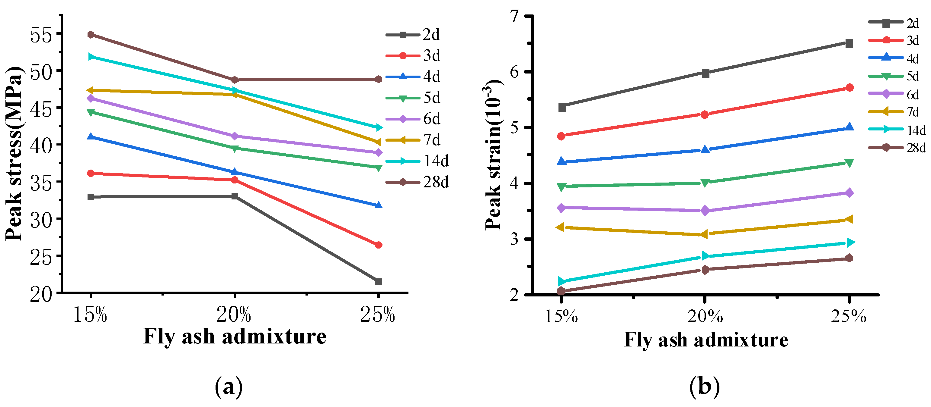
When the fly ash admixture increases from 15% to 25%, the variation in peak stress and strain of manufactured sand concrete is shown in Figure 6. The peak stress decreases with the increase in fly ash admixture. With different curing ages, the variation in peak stress presented some differences with the increase in fly ash admixture. At the age of 2d to 3d, it is small when the fly ash admixture increases from 15% to 20%, but it changes greatly (a decrease at about 10 MPa) when the fly ash admixture increases from 20% to 25%. Along with the increase in curing age, the peak stress changes less from 15% to 20% than that from 20% to 25%. As for the peak strain, it increases linearly with the increase in fly ash. Similar to the tendency of water–binder ratio, the peak strain changes obviously at the early age. When the fly ash admixture increases from 15% to 25%, the change in peak strain is about 1 × 10⁻³ at the ages of 2d to 4d, while it is about 0.5 × 10⁻³ at the ages of 5d to 28d. This finding shows that the relationship between peak stress and strain and fly ash admixture is limited by the curing age, especially the early age. The effect of fly ash on concrete properties is mainly expressed in two aspects. First, the appropriate amount of fly ash improves the fluidity of fresh concrete, reduces the phenomenon of water bleeding, and improves the compactness of concrete by optimizing the pore structure distribution of hardened cementitious paste [22]. Second, excessive fly ash can adversely affect the construction properties of fresh concrete and the pore structure of hardened concrete, which can lead to a decrease in mechanical properties and durability.

4. Modeling of the Constitutive of Early Age Manufactured Sand Concrete

4.1. Fitting Analysis with the Existing Models

To grasp the uniaxial compressive stress and strain relationship of concrete, researchers have developed various constitutive models. Among them, the most typically and commonly used constitutive models are Carreira model [23], Wee model [24], Yang model [25], Sargin model [26], GB 50010-2010 model [27], and Guo model [28], etc. Some brief descriptions of these models follow.
With the analyses of numerous groups of ordinary concrete (the axial compressive strength ranged from 7.6 MPa to 140 MPa), Carreira established a relatively simple model to express the rising and falling sections of stress–strain, as shown in the following formula:
y = β x β 1 + x β
where y = f / f c , f represents the axial stress, f c represents the peak stress, x = ε / ε c , ε represents the axial strain (10−6), ε c represents the peak strain (10−6), β is the model parameter, β = 1 / 1 ( f c / ε c E c ) , and E c represents the elastic modulus of concrete, E c = 10,200 ( f c ) 1 / 3 . The same symbol indicates the same meaning in the following parts, and the same introduction is omitted.
Based on the Carreira model, Wee established the uniaxial compression constitutive model that considered high-strength concrete with strength from 50 MPa to 120 MPa, as shown in the following formula:
y = k 1 β x k 1 β 1 + x k 2 β
where when the compression strength fc is small than 50 MPa, the value of k1 and k2 both take 1. When the compression strength fc ranges from 50 MPa to 120 MPa, the value of k1 and k2 is calculated by the following equations.
k 1 = ( 50 / f c ) 3
k 2 = ( 50 / f c ) 1.3
Keun-Hyeok Yang established a single equation to express the rising and descending sections based on the study of the stress–strain relationship of concrete, as shown in the following formula:
y = ( β 1 + 1 ) x β 1 + x β 1 + 1
The constitutive model expression proposed by Sargin is as follows:
y = c 1 x + ( c 2 1 ) x 2 1 + ( c 1 2 ) c 2 x 2
c 1 = E c ε c / f c  
  c 2 = 0.65 7.25 f c × 10 3
The constitutive model established by Guo adopts segmented equations, and the ascending and descending sections are:
y = a x + ( 3 2 a ) x 2 + ( a 2 ) x 3 x b ( x 1 ) 2 + x
where parameter a represents the ratio of the initial elastic modulus of concrete to the elastic modulus under peak load; the value of parameter b is related to the concrete strength class and constraint method.
The constitutive model used in China’s concrete structure design code is detailed in Equations (8) and (9).
σ = ( 1 - d c ) E c ε
d c = 1 ρ c n n 1 + x n     x 1 1 ρ c α c ( x 1 ) 2 + x       x > 1
ρ c = f c E c ε c
n = E c ε c E c ε c f c
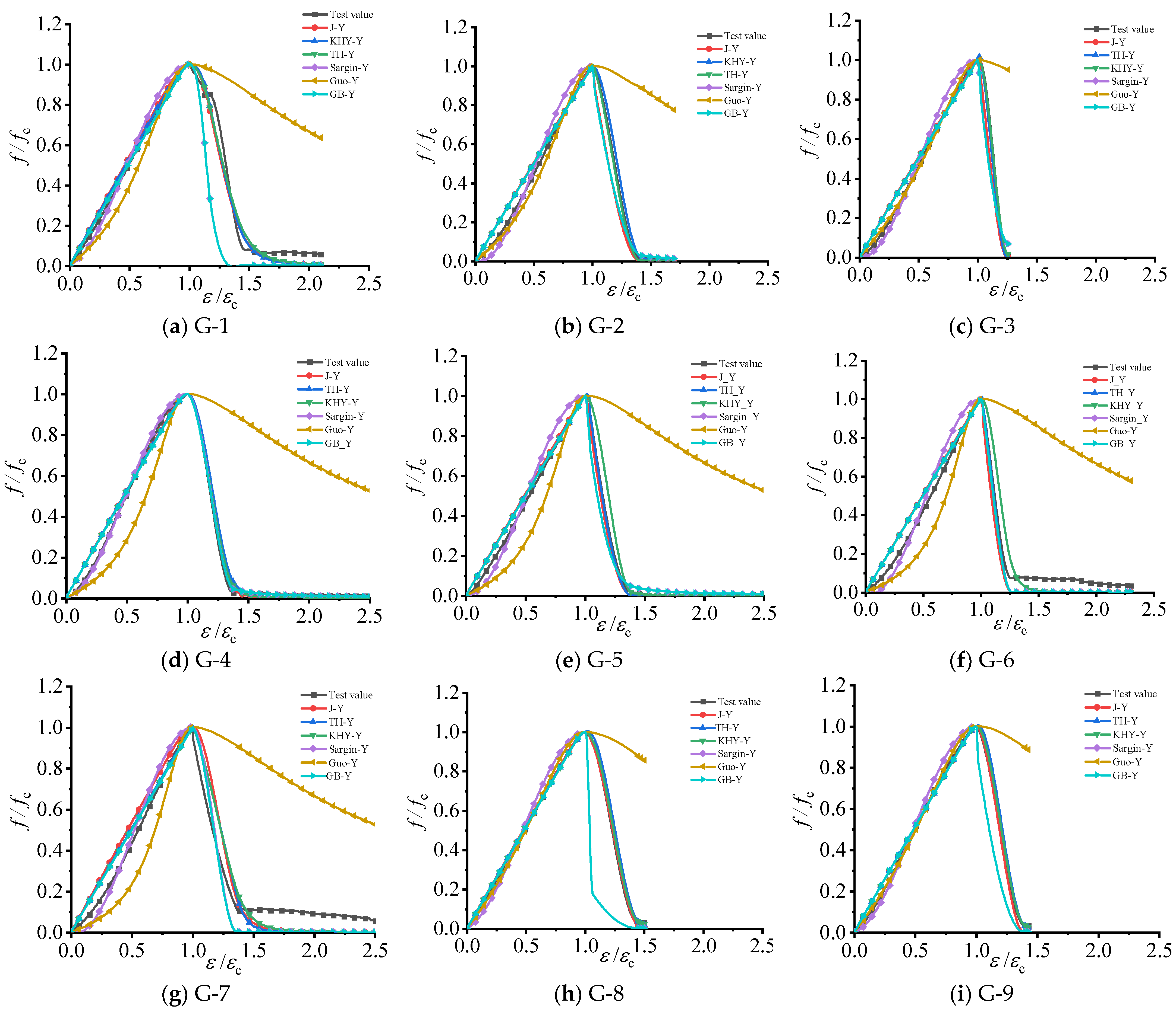
To establish the early age uniaxial compressive constitutive model of manufactured sand concrete, the stress–strain curves of manufactured sand concrete with different water–binder ratios and fly ash admixtures at the age of 5 days were fitted by using six component models. The fitting results for the remaining ages are similar to this age, and the fitting results are shown in Figure 7.
Figure 7 shows that the Guo model has poor fitting results, while the GB 50010-2010 model presents better fitting results in the ascending section but is poor in the descending section. As for the other models, the Carreira model, Wee model, Yang model, and Sargin model can well fit the variation tendency of the test results, but there were still some gaps in accuracy. To select the appropriate model for the early age manufactured sand concrete, the correlation coefficient (R2), mean squared error (MSE), and mean absolute error (MAE) were used to evaluate the fitting performance [29]. The expression of R2, MSE, and MAE are shown as follows.
R 2 = 1 i = 1 n ( y i y ^ i ) 2 i = 1 n ( y i y ¯ ) 2
M S E = 1 n i = 1 n ( y i ^ y i ) 2
M A E = 1 n i = 1 n y i ^ y i
where y ¯ represents the average value, y i represents the true value, and y ^ i the predicted value of the model. The closer the R2 is to 1, the smaller the MSE and MAE are, indicating a better fit and accuracy of the model.
Table 3 reveals that the Carreira model exhibits the highest average value of R2, while the Sargin model demonstrates the lowest average value of MAE, and the Wee model has the smallest average value of MSE. This indicates that all three models can serve as the basis for the intrinsic model. However, due to its simplicity in practical applications, the Sargin model can be employed as the foundation for the stress–strain curve model of manufactured sand concrete. While there are other available models, the Sargin model was selected as the base model considering factors such as prediction accuracy and computational complexity.
It is important to note that although the Sargin model performs well in predicting the rising section of the stress–strain curve for manufactured sand concrete, the prediction results for the falling section are not satisfactory and may not completely reflect the trend. To accurately depict the stress–strain relationship of manufactured sand concrete at different ages, the parameters are modified based on the Sargin model to obtain a stress–strain model that is relevant to manufactured sand concrete at various ages.

4.2. Stress–Strain Curve Parameters Concerning Different Variables

The stress–strain curve is influenced by three main factors: peak stress, peak strain, and modulus of elasticity. These factors affect the damage pattern, deformation behavior, shape of the complete curve, slope of the falling section, and residual strength. It is essential to explore the relationship between each variable and characteristics such as the peak stress in the stress–strain curve. Additionally, the parameters of the Sargin model are adjusted to examine the effects of factors such as age, water–binder ratio, and fly ash admixture on the Sargin model.

4.2.1. Elastic Modulus

Based on the analysis of previous test results, it can be concluded that an increase in the peak stress of the concrete specimen corresponds to an increase in the modulus of elasticity. The experimental research conducted in the previous chapter reveals that the water–binder ratio, fly ash content, and age have significant effects on the elastic modulus. Consequently, the following mathematical formula models can be derived:
(1)
t → ∞, Ec tends to a certain value;
(2)
t → 0, Ec → 0;
(3)
dE/dt decreases as the age t changes;
(4)
Ec = c × e^(−d/t), d > 0, c is generally the modulus of elasticity at age 28d.
The relationship equation between peak stress and modulus of elasticity appropriate to manufactured sand concrete was derived in Equation (10) after regression analysis of 72 sets of test data.
f co = 6.82 E c 1.64
where fco represents peak stress (MPa), and Ec represents modulus of elasticity (104 MPa).

4.2.2. Peak Stress

Peak stress plays a crucial role in the stress–strain model, and the different effects of water–binder ratio, fly ash content, and age on peak stress can be found through the experimental studies in the previous chapters. The following mathematical formula models can be derived:
(1)
When t tends to 0, the peak stress also tends to 0;
(2)
When the age t tends to infinity, the peak stress should gradually converge to a certain value;
(3)
The growth rate of the function decreases with age, that is, t tends to infinity, and the derivative of y tends to 0;
(4)
t → 0, y → 0.
Therefore, the functional model of Equation (11) is used for regression analysis in this paper.
f co = ( a × W / B + b × F + c ) × ( d + e × e x p ( f / t ) )
where W/B represents the water–binder ratio of concrete; F represents the content of fly ash admixture; t represents the age (d); fco represents peak stress (Mpa); and a, b, c, d, and g are the parameters of the model. With the 72 sets of test results, the fitting parameters were obtained and the model of peak strain fco was characterized as follows:
f co = ( 16.586 × W / B 17.939 × F + 14.658 ) × ( 2.78 + 5.867 × e x p ( 2.579 / t ) )

4.2.3. Peak Strain

The magnitude of the peak strain εc is influenced by various factors, such as the concrete strength, test loading rate, specimen size, confinement method, and inherent discreteness of the concrete material itself. In the case of unconstrained concrete under uniaxial loading, the peak strain is primarily determined by the concrete strength, which is correlated with factors such as water–binder ratio, age, and fly ash content [30]. Other factors that can affect the peak strain include concrete age, humidity, temperature, and stiffness of the testing apparatus. Therefore, establishing an accurate model for peak strain is of great significance for a comprehensive understanding of the stress–strain relationship of manufactured sand concrete.
According to the experimental data, the peak strain of concrete is regressed in this study. Three regression types are considered: exponential, power function, and linear, as follows:
a.
The linear regression form assumes a directly proportional relationship between peak strain and strength, ε c = a × f c + b ;
b.
The power function regression form assumes a non-linear relationship between peak strain and strength, where the trend is influenced by power, ε c = a × ( f c ) b ;
c.
The exponential regression form considers a complex exponential function between peak strain and strength, ε c = a × e ( b f c ) .
The data were fitted using MATLAB software, and 72 data sets were substituted for the calculation. The fitting results are shown in Table 4; all three regression forms fit the data well, but the power function regression form fits the data best, followed by the exponential regression form and finally the linear regression form.
Table 4 shows that the exponential model has the best fit, but as age and other variable factors must be taken into account, the compound model is utilized, and the fitting method is given in Equation (20).
ε co = ( a + b × W / B + c × F ) × ( d + g × f t )
where W/B represents the water–binder ratio of concrete; F represents the content of fly ash admixture; t represents the age (d); ε co represents the peak strain (10−3); a, b, c, d, and g are the parameters of the model. With the 72 sets of test results, the fitting parameters were obtained and the model of peak strain ε co was characterized as follows:
ε co = ( 2.995 + 11.954 × W / B + 3.939 × F ) × ( 1.301 + 3.388 × 0.75 t )

4.3. Constitutive Model of Early Age Manufactured Sand Concrete

According to Equation (19), the prediction model of peak stress can be derived, which reflects the influence of test variables such as fly ash admixture, age, and water–binder ratio on the concrete, because the prediction models of modulus of elasticity and peak strain are both functions of peak stress. The influence of the variables on the model under different fitting ratios and ages can be expressed more comprehensively.
The correction factor k was introduced based on the Sargin model parameters to express the effects of age, water–binder ratio, fly ash admixture, and other factors on the concrete stress–strain curve’s characteristics, and the equation’s functional model expressions (22) and (23) were obtained.
When k = 1, Equation (21) has the same form as the Sargin model. The introduction of the correction factor more accurately reflects the deformation characteristics of the manufactured sand concrete at different ages, thus, improving the accuracy of the model.
f = f co c 1 k ε / ε co + ( c 2 1 ) ε / ε co 2 1 + ( c 1 k 2 ) c 2 ε / ε co 2
k = 1                     ( ε ε c ) 0.1033 [ ( f / f c , 28 ) 0.682 + 5.5 ]       ( ε > ε c )
c 1 = E c ε co / f co   ,   c 2 = 0.65 7.25 f co × 10 3
where f represents axial stress (MPa), ε represents axial strain (10−3), ε co represents peak strain (10−3), fco represents peak stress (MPa); Ec represents modulus of elasticity (104 MPa) and fc,28 represents peak stress of concrete specimens of the same ratio at 28 days of age (MPa).
When Xie [17] studied the constitutive model of manufactured sand concrete, it was also based on Sargin’s model, and his experimental variables were concrete strength and stone dust content, etc., so the constitutive model he derived was changed into a segmental equation on the premise of Sargin’s model. In this paper, the test variables are age, water–cement ratio, and fly ash admixture, etc., so the constitutive model of this paper is different from that of Xie’s study, which is predominantly manifested in the increase in the influence factor k.
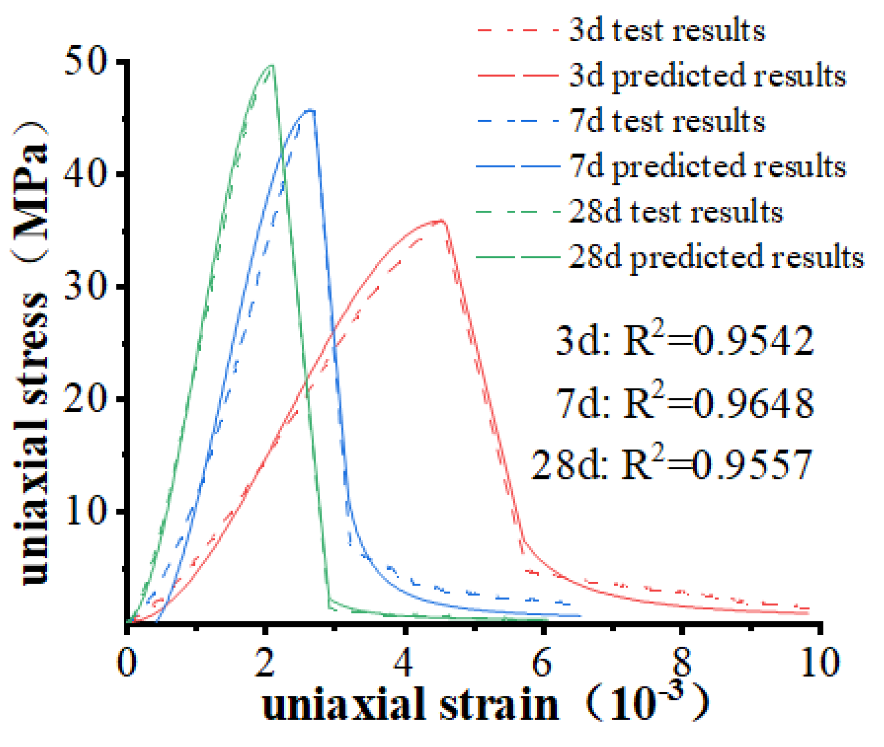
To test the predictive efficacy of Equation (22), three additional sets of tests (G-1, t-3d, 7d, and 28d) were selected to validate the effect of the modified stress–strain model, and the results are plotted in Figure 8.
According to Figure 8, the modified model shows high accuracy in predicting the findings for each group of specimens, which could reflect the measured curves more realistically. Among them, the fit R2 of the modified model for 3 days, 7 days, and 28 days ages all reach above 0.95. Therefore, the prediction effect is significantly improved and exhibits good prediction performance.
Therefore, the stress–strain curve at the corresponding age can be predicted by the constitutive model, and the peak stress and peak strain data of concrete at that age can be obtained to judge whether the next stage of construction can be carried out.

5. Application of the Constitutive Model

Building upon the initial research conducted on the axial compression behavior of early age manufactured sand concrete, the aforementioned constitutive model is employed for the calculation of real-world projects. This involves combining measured data with theoretical analysis results and utilizing the ABAQUS finite element software to analyze and discuss the weaknesses identified. By comparing actual measurements and model simulations, the weak points of the bridge pier climbing cone are analyzed. Based on this analysis, optimization suggestions and measures are provided to address these weaknesses.

5.1. Build Finite Element Model

5.1.1. Basic Assumptions

In the calculation of the stress field, concrete is initially treated as a homogeneous isotropic material, considering its properties as an elastic–plastic material. The deformation of formwork during concrete placement is not taken into account, but uniform shrinkage deformation within the concrete is assumed. Additionally, simplified modeling is employed by utilizing the principle of elastic modulus equivalence for reinforced concrete. Furthermore, a locally refined finite element model is established based on the Saint-Venant principle.
During the finite element modeling process, it is often challenging to unify the fundamental properties of materials, making it difficult to achieve a monolithic modeling approach. While separated modeling can address this issue, it may impact the overall simulation and analysis effectiveness. To overcome this, scholars such as Zhang [31] and Xu [32] have effectively modeled the modulus of reinforcement and concrete through the modulus equivalence principle. This approach enables fast and efficient finite element modeling, enhancing the accuracy and stability of the modeling process and providing reliable support for practical engineering applications.

5.1.2. Finite Element Model

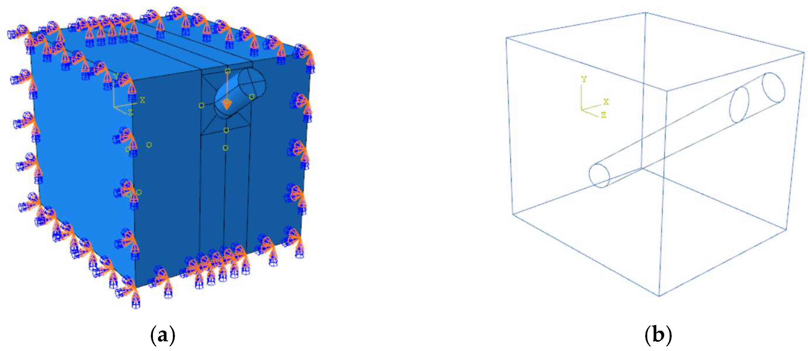
The local refined finite element model of the bridge abutment’s pier body was established using ABAQUS. The pre-buried steel bar material was selected as 40Cr steel, with corresponding material properties. The pier concrete material grade is C50, and the stress–strain relationship described in the previous Section 4.3 is combined with Saint-Venant’s principle to further establish the local refined finite element model of the bridge pier, as shown in Figure 9.
The model’s dimensions are 4 m in the Z-direction and 3.5 m × 3.5 m in the X–Y section. Figure 9a depicts the coupling effect between the crawling cone and the midpoint of the concrete’s X–Y face. The loading method employed in the model is displacement loading, which allows for control of the external force applied to the model. This method effectively simulates the actual loading conditions. By considering the coupling effect, the accuracy of the simulation results is significantly improved.
Regarding the boundary conditions of the model, the primary consideration is to restrict the degrees of freedom at the upper loading end of the specimen (U1, U2, U3) and at the bottom (U1, U2, U3) in two and three directions, respectively. By coupling the action point of the crawling cone with the upper part point of the contact surface, the external force is indirectly applied to the crawling cone.
In terms of contact interaction, the crawling cone body and the concrete are modeled separately to account for their distinct material properties. Additionally, separate plastic damage models are employed for each component. For the crawling cone component, a plastic damage model for concrete with an age of 10 days is utilized, while the corresponding plastic damage model for concrete is employed based on its different ages. Consequently, normal and tangential friction coefficients are employed to define the contact behavior between these two parts. Specifically, a hard contact is set in the normal direction, while a friction coefficient of 0.3 is chosen for the tangential direction based on several trial calculations to achieve results that align more closely with the actual deformation.

5.2. On-Site Monitoring Program

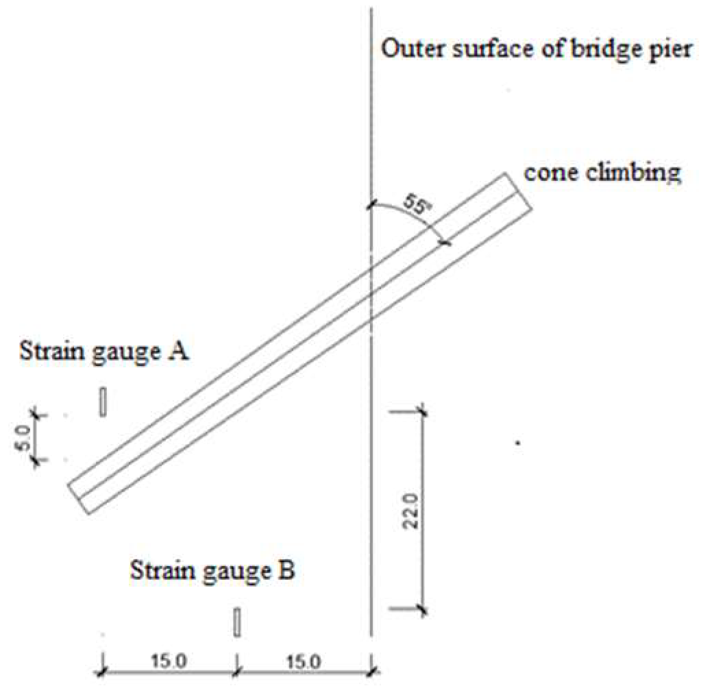
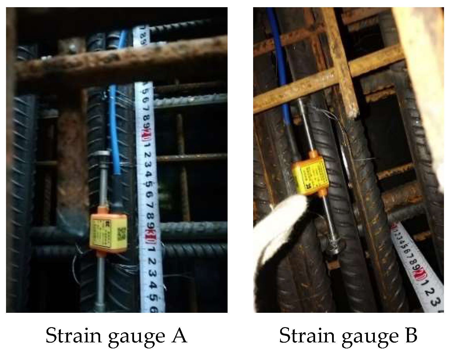
Due to the complexities involved in the crawling formwork and reinforcement tying on the construction site, it was not feasible to place strain gauges directly on the concrete surface near the crawling cone. To address this challenge, pre-buried strain gauges were employed in the concrete near the crawling cone. Specifically, strain gauges A and strain gauges B were buried in the end part of the crawling cone, as illustrated in Figure 10. The pre-buried strain gauges utilized were intelligent string strain gauges manufactured by Changsha Golden Code Company (Changsha, China) (Figure 11). The measurement apparatus used was a comprehensive tester also provided by Changsha Golden Code Company. This approach allowed for effective strain measurement while minimizing disruption to the construction process.

5.3. Analysis of Finite Element Model Results

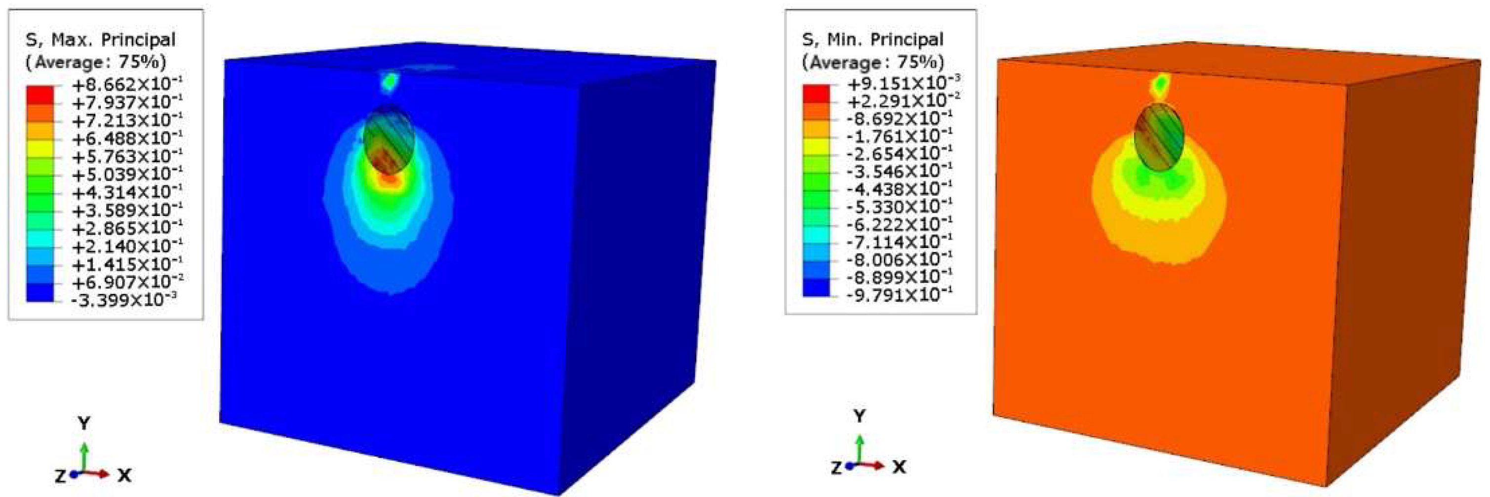
Simulation calculations and analysis have been conducted for the construction process of the critical sections of the pier. The stress analysis results are presented in Figure 12, while the strain analysis results are summarized in Table 5.
The stress field clouds depicted in Figure 12 at different ages illustrate a significant increase in stress at the contact point between the crawling cone and the concrete at the age of 3d. This can be attributed to the intense hydration reaction of the concrete at earlier ages, which means that the concrete’s strength does not increase instantaneously. Consequently, the resistance of the concrete is relatively weak at this stage. As the concrete reaches the ages of 4d and 5d, the hydration reaction becomes more stable, leading to a substantial increase in overall strength. Consequently, the concrete’s ability to withstand external forces is enhanced. Furthermore, variations in stress distribution within the concrete can also be observed at different ages, which influences the performance of the concrete.
From Table 5, it can be observed that the concrete at strain gauge B experiences tension. This can be attributed to the positioning of the buried strain gauges. Specifically, the concrete strain gauge at strain gauge B is located closer to the end of the crawling cone in the tensile section, resulting in a positive strain value. The difference between the measured and simulated strain values near the crawling cone is within 10%, indicating that the simulation results obtained from the established finite element model are accurate and consistent with the actual force conditions during construction. This also serves as validation for the rationality of the ontological model of early age manufactured sand concrete established in the previous study.

6. Conclusions

In this paper, the effects of age, water–cement ratio, and fly ash dosage on the stress–strain curve of uniaxial compression of mechanized sand concrete were investigated through experiments. Based on the experimental data, the constitutive model of early age mechanized sand concrete was established, and the key sections of bridge piers were simulated and analyzed by using ABAQUS software, and the reasonableness of the constitutive model was verified. The primary conclusions are as follows:
(1) Based on the test data, after comparing and analyzing six models, the average value of R2 of Sargin model is 0.9775, the average value of MAE is 0.1335, and the average value of MSE is 0.0024. The Sargin model is corrected, and the early age manufactured sand concrete constitutive model is proposed;
(2) The peak tension of concrete is positively correlated with the change in age; the peak strain of concrete is negatively correlated with the change in age;
(3) With the growth in age, the growth in peak stress of concrete can be divided into two phases, the first stage is from 2 to 7 days, and the average increment in peak stress is 20 MPa; the second stage is from 7 to 28 days, and the average increment is 8 MP;
(4) The peak stress of concrete is negatively correlated with the change in water–cement ratio; the peak strain of concrete is positively correlated with the change in water–cement ratio;
(5) The peak tension of concrete is negatively correlated with the change in fly ash admixture; the peak strain of concrete is positively correlated with the change in fly ash admixture;
(6) Based on the early age manufactured sand concrete constitutive model proposed in this paper, ABAQUS finite element software is used to simulate and analyze the key parts of the bridge abutment, and the difference between its simulated value and the measured value is within 10%, which indicates the reasonableness of the modified model in this paper.

Author Contributions

Conceptualization, G.P.; methodology, N.L.; software, B.L. and H.X.; investigation, H.X. and B.L., writing—original draft, H.X.; writing—review and editing, N.L. All authors have read and agreed to the published version of the manuscript.

Funding

The support from Natural Science Basic Research Program of Shaanxi (Program No. 2022JQ-560) is greatly appreciated.

Data Availability Statement

The data presented in this study are available on request from the corresponding author. The data are not publicly available as they form part of an ongoing study.

Conflicts of Interest

The authors declare no conflict of interest.

References

  1. Wang, X.; Liu, M.; Liu, X. Study on mechanical properties and carbon emission of desert sand and manufactured sand concrete. J. Civ. Eng. 2022, 55, 23–30. [Google Scholar]
  2. Xiao, C.; Guo, Y.; Li, B.; Zhou, M.; Li, B.; Liu, Z.; Zhou, J. Coupled effects of the content and methylene blue value (MBV)of microfines on the performance of manufactured sand concrete. Constr. Build. Mater. 2020, 240, 17953. [Google Scholar]
  3. Shen, W.; Liu, Y.; Wang, Z.; Cao, L.; Wu, D.; Wang, Y.; Ji, X. Influence of manufactured sand’s characteristics on its concrete performance, Constr. Build. Mater. 2018, 172, 574–583. [Google Scholar] [CrossRef]
  4. Shen, W.; Yang, Z.; Cao, L. Characterization of manufactured sand: Particle shape, surface texture and behavior in concrete. Constr. Build. Mater. 2016, 114, 595–601. [Google Scholar] [CrossRef]
  5. Deng, C.; Yan, J.; Ye, X. Research on the effect of manufactured sand admixture on mechanical properties and volume stability of concrete. New Build. Mater. 2018, 45, 42–46. [Google Scholar]
  6. Zhang, M.H. Microstructure, crack propagation, and mechanical properties of cement pastes containing high volumes of fly ashes. Cem. Concr. Res. 1995, 25, 165–1178. [Google Scholar] [CrossRef]
  7. De la Varga, I.; Spragg, R.P.; Di Bella, C.; Castro, J.; Bentz, D.P.; Weiss, J. Fluid transport in high volume fly ash mixtures with and without internal curing. Cem. Concr. Compos. 2014, 45, 102–110. [Google Scholar] [CrossRef]
  8. Juang, C.; Kuo, W. Properties and Mechanical Strength Analysis of Concrete Using Fly Ash, Ground Granulated Blast Furnace Slag and Various Superplasticizers. Buildings 2023, 13, 1644. [Google Scholar] [CrossRef]
  9. Wu, H.; Hu, R.; Yang, D.; Ma, Z. Micro-macro characterizations of mortar containing construction waste fines as replacement of cement and sand: A comparative study. Constr. Build. Mater. 2023, 383, 131328. [Google Scholar] [CrossRef]
  10. Zhang, M.; Xu, J.; Li, M.; Yuan, X. Influence of Stone Powder Content from Manufactured Sand Concrete on Shrinkage, Cracking, Compressive Strength, and Penetration. Buildings 2023, 13, 1833. [Google Scholar] [CrossRef]
  11. Ma, Z.; Shen, J.; Wang, C.; Wu, H. Characterization of sustainable mortar containing high-quality recycled manufactured sand crushed from recycled coarse aggregate. Cem. Concr. Compos. 2022, 132, 104629. [Google Scholar] [CrossRef]
  12. Gao, Y.; Ren, X.; Zhang, J. Proposed constitutive law of uniaxial compression for concrete under deterioration effects. Bull. Chin. Ceram. Soc. 2020, 13, 2048. [Google Scholar] [CrossRef] [PubMed]
  13. Li, Z.; Wang, G.; Yang, S. Experimental study on mechanical properties and stress-strain principal relationship of desert sand concrete. J. Appl. Mech. 2019, 36, 1131–1137+1261. [Google Scholar]
  14. Ju, G.; Li, Z.; Wang, W. Experimental study on axial compression performance of sand concrete in Gurbantunggut desert. Concrete 2019, 4, 33–36. [Google Scholar]
  15. Gao, Y.; He, Z.; Song, L. Influence of manufactured sand mixing rate on mechanical properties of plastic concrete. People’s Yellow River 2019, 41, 148–151+157. [Google Scholar]
  16. Chen, Z.; Qin, Y.; Liu, G. Experimental study on the principal relationship of manufactured sand concrete after high temperature. Concrete 2013, 12, 72–74+86. [Google Scholar]
  17. Xie, K.; Liu, Z.; Gai, B.; Zhu, M.; Xin, Y. Experimental study on stress-strain of manufactured sand concrete. Silic. Bull. 2020, 39, 3823–3831. [Google Scholar]
  18. Xie, K.; Liu, Z.; Gai, B.; Xin, Y.; Zhu, M. Ontogenetic relationships and mechanical properties of concrete with manufactured sand of different lithologies. J. Archit. Civ. Eng. 2021, 38, 99–106. [Google Scholar]
  19. JGJ 55-2011; Design of Ordinary Concrete Proportions. Ministry of Housing and Urban Rural Development of the People’s Republic of China: Beijing, China, 2011. Available online: https//www.doc88.com/p-1166129088978.html (accessed on 3 August 2023).
  20. Guo, Z.; Shi, X. Principles and Analysis of Reinforced Concrete; Tsinghua University Press: Beijing, China, 2003. [Google Scholar]
  21. Xu, Z.; Yuan, Q.; Yang, Z. Mechanical properties of early-age concrete and its uniaxial principal structure model. J. SUT 2015, 5, 92–96. [Google Scholar]
  22. Liu, S.; Yan, P. Effect of limestone powder on the filling effect of cement slurry and pore structure of mortar. J. Chin. Ceram. Soc. 2008, 36, 5. [Google Scholar]
  23. Carreira, D.J.; Chu, K. Stress-strain relationship for plain concrete in compression. J. Am. Concr. Inst. 1985, 82, 797–804. [Google Scholar]
  24. Wee, T.; Chin, M.; Mansur, M. Stress-Strain Relationship of High-Strength Concrete in Compression. J. Mater. Civ. Eng. 1996, 8, 70–76. [Google Scholar] [CrossRef]
  25. Yang, K.; Mun, J.; Cho, M. Stress-Strain Model for Various Unconfined Concretes in Compression. ACI Struct. J. 2014, 111, 819–826. [Google Scholar] [CrossRef]
  26. Sargin, M. Stress-Strain Relationship for Concrete and the Analysis of Structural Concrete Sections. Master’s Thesis, University of Waterloo, Waterloo, ON, Canada, 1971. [Google Scholar]
  27. GB 50010-2010; Code for the Design of Concrete Structures. China Architecture & Building Press: Beijing, China, 2015.
  28. Guo, Z.; Zhang, X.; Zhang, D. Experimental study of the full stress-strain curve of concrete. J. Build. Struct. 1982, 3, 1–12. [Google Scholar]
  29. Zhang, W.; Ye, J.; Bai, Z.; Li, X. Intersection queue length estimation method based on networked vehicle trajectory data. Chin. J. Highw. 2022, 35, 216–225. [Google Scholar]
  30. Samani, A.; Attard, M. A stress–strain model for uniaxial and confined concrete under compression. Eng. Struct. 2012, 41, 335–349. [Google Scholar] [CrossRef]
  31. Zhang, Y. Experimental Study on the Macroscopic Constitutive Relationship of Reinforced Concrete in Axial Compression. Master’s Thesis, Chongqing Jiaotong University, Chongqing, China, 2013. [Google Scholar]
  32. Xu, J. Research on the Whole-Process Analysis Method of Hollow Slab Beams Based on the Unified Constitutive of Steel Reinforcement. Master’s Thesis, Chongqing Jiaotong University, Chongqing, China, 2014. [Google Scholar]
Figure 1. Test device.
Buildings 13 02187 g001
Figure 2. Axial compressive stress–strain curve of classical manufactured sand concrete specimens. Point A is the elastic limit point, point B is the plastic limit point, and point C is the peak stress point.
Buildings 13 02187 g002
Figure 3. Damage pattern of specimens at different ages, (a) 2d, (b) 3d, (c) 7d, (d) 14d.
Buildings 13 02187 g003
Figure 4. Variation in peak stress and peak strain with age in each test group; (a) peak stress; (b) peak strain.
Buildings 13 02187 g004
Figure 5. Variation in peak stress and peak strain with water–binder ratio in each test group; (a) peak stress; (b) peak strain.
Buildings 13 02187 g005
Figure 6. Variation in peak stress and peak strain with fly ash admixture in each test group; (a) peak stress; (b) peak strain.
Buildings 13 02187 g006
Figure 7. The test curve is compared with the curve of each model. In the figure, J-Y represents the Carreira model, TH-Y represents the Wee model, KHY-Y represents the Yang model, Sargin-Y represents the Sargin model, Guo-Y represents the Guo model, and GB-Y represents the GB 50010-2010 model.
Buildings 13 02187 g007
Figure 8. Comparison of measured data and predicted results.
Buildings 13 02187 g008
Figure 9. Finite element model. (a) Refined finite element model; (b) finite element model perspective view.
Buildings 13 02187 g009
Figure 10. Embedded strain gage solutions.
Buildings 13 02187 g010
Figure 11. Actual embedded strain gage diagram.
Buildings 13 02187 g011
Figure 12. Stress clouds from refined finite element model analysis.
Buildings 13 02187 g012
Table 1. Physical properties of cement.
ProjectDensity (g·cm−3)Specific Surface Area (cm2·g−1)Setting Time
(min)
Flexural Strength
(MPa)
Compressive Strength
(MPa)
Initial Setting TimeFinal Setting Time3d3d
Technical indicators3.134502042726.533.4
Table 2. Manufactured sand concrete mix ratio design.
GroupWater-to-Binder RatioFly Ash AdmixtureSand RateCoarse Aggregate
Proportioning
10~20 mm:5~10 mm
Water Consumption (kg)Super-Plasticizer Amount (%)
G-10.3215%42%6:41651.2
G-20.3220%42%6:41651.2
G-30.3225%42%6:41651.2
G-40.3415%42%6:41651.2
G-50.3420%42%6:41651.2
G-60.3425%42%6:41651.2
G-70.3615%42%6:41651.2
G-80.3620%42%6:41651.2
G-90.3625%42%6:41651.2
Table 3. Six models fit performance evaluation results.
Work ConditionsEvaluation IndicatorsJ-YTH-YKHY-YSargin-YGuo-YGB-Y
G-1R20.98840.96920.98240.91620.67710.8750
MAE0.10760.09730.09730.12092.00900.8584
MSE0.00040.00040.00040.00051.19550.4010
G-2R20.98170.98310.98330.95480.76080.9182
MAE0.62950.21100.39150.30662.34950.7706
MSE0.05860.00820.02430.01751.61180.0872
G-3R20.98190.98360.98380.99730.61970.8810
MAE0.12780.12520.13580.12113.12580.8574
MSE0.00060.00060.0060.00052.04520.4007
G-4R20.99070.99070.89080.99170.69870.8916
MAE0.10310.10140.09980.09863.88320.6899
MSE0.00040.00040.0040.00042.25080.0247
G-5R20.99250.99430.99440.99540.68170.9213
MAE0.11640.13590.12360.09983.85630.2754
MSE0.00050.00060.00060.00042.24870.0091
G-6R20.95800.95960.86350.95910.67420.9046
MAE0.13080.14120.23560.13393.79810.8962
MSE0.00060.00060.00830.00062.15850.0844
G-7R20.93140.94100.84650.94860.67580.8740
MAE0.24020.21850.23970.12253.65960.9698
MSE0.00860.00810.00840.00062.09830.4088
G-8R20.99790.99860.99870.99360.88130.8958
MAE0.09850.09980.09560.10031.18751.1981
MSE0.00040.00040.00040.00040.63520.6392
G-9R20.99300.99250.99130.99620.88980.8917
MAE0.10050.09720.10820.09751.12751.1382
MSE0.00040.00040.00040.00040.61630.6197
Average valueR20.97950.97920.94830.97750.72880.8948
MAE0.18320.13640.17010.13352.78640.8348
MSE0.00780.00220.00490.00241.65110.2972
Table 4. Fit the model results.
Fitting the Model ε c = a × f c + b ε c = a × ( f c ) b ε c = a × e ( b f c )
Parametersababab
0.23590.00621.639−1.107814.3530.0338
Goodness-of-fit R20.80190.84790.9056
Table 5. Measured and simulated data table of strain near the climbing cone.
Relative LocationData3d4d5d
(Strain gauge A)Measured value (με)−28.4−33.6−46.4
Simulated values (με)−30.6−35.8−42.4
Difference values (%)7.66.59.4
(Strain gauge B)Measured value (με)8.59.727.6
Simulated values (με)9.310.629.3
Difference values (%)9.49.26.2
Disclaimer/Publisher’s Note: The statements, opinions and data contained in all publications are solely those of the individual author(s) and contributor(s) and not of MDPI and/or the editor(s). MDPI and/or the editor(s) disclaim responsibility for any injury to people or property resulting from any ideas, methods, instructions or products referred to in the content.