Abstract
The stability of underground diaphragm walls is crucial for ensuring the safety and integrity of trench excavations in geotechnical engineering. This study addresses this critical issue by proposing a novel destabilization mechanism based on a sliding body model specifically designed for diaphragm wall trenching operations. The research employs an analytical framework rooted in soil mechanics and plasticity theory, utilizing limit equilibrium analysis to develop a method for calculating the minimum required slurry density and corresponding safety factor for trench stability. The study compares two distinct approaches to slurry density computation, analyzing their sensitivity to various influencing factors. Theoretical findings are validated through multiple real-world engineering case studies. Comparative analysis demonstrates the superiority of the proposed method, particularly in assessing trench stability within clay layers. Key variables influencing the safety factor are identified, including trench length, slurry density, soil friction angle, and the relative height difference between slurry and groundwater levels. Results indicate that actual slurry densities observed in practice consistently fall within the bounds predicted by the theoretical calculations. This research contributes a valuable theoretical framework to the field of diaphragm wall construction, offering improved accuracy in stability assessments and potentially enhancing safety in geotechnical engineering projects.
1. Introduction
In the complex interplay of construction, geotechnics, and structural integrity, diaphragm walls emerge as a fundamental component in modern trench excavation. Their role in maintaining subterranean stability is crucial, especially in urban environments where deep excavations are integral to infrastructure development [,,,]. This research is driven by the critical need to safeguard the integrity of trench excavations, where stability against subsoil pressures relies on the precision of diaphragm wall construction techniques [,,]. At its core, this study explores a novel destabilization mechanism governing the stability of these walls during the trenching process, aiming to revolutionize construction practices and enhance onsite safety [,].
The following Table 1 summarizes key research contributions in the field of diaphragm wall trenching, listed in chronological order.

Table 1.
Summary of key contributions to the study of diaphragm wall trenching construction.
Trench stability analysis in diaphragm wall construction, while extensively studied, still presents opportunities for enhancement. Traditional approaches have primarily relied on static models, which oversimplify the dynamic conditions present at construction sites. Existing studies outline various methods for assessing stability, focusing on parameters such as slurry density and hydrostatic equilibrium. Chen et al. [] addressed the inclusion of green technologies in diaphragm wall construction, proposing a novel framework but grappling with its adaptability to varying earth conditions. Lim et al. [] employed finite element analysis to manage excavation-induced deformations, acknowledging uncertainties due to soil behavior inconsistencies. Zhong et al. [] and Makasis and Narsilio [] investigated the thermal performance of energy walls, providing crucial insights for geothermal applications despite limitations related to thermal dynamics and long-term viability. Yao et al. [] presented a structural adjustment approach for diaphragm walls’ seismic resilience, which shows promise but requires validation against diverse seismic conditions. Dai et al. [] explored the prolonged behavior of stiff clays, informative yet narrow in scope. Wang and Huang [] scrutinized trench stability in stratified soil constructs, enriching understanding but still pending field verification.
While these contributions advance sustainable building techniques, they highlight the need for continued exploration to improve both versatility and foresight in subsurface construction models. Notably, existing strategies often fail to account for the evolving timescale of trenching operations—a critical aspect considering the temporal variability of soil characteristics and construction phases. Thus, adopting a time-sensitive analysis is not merely an academic exercise but a practical imperative, underscoring the importance of expanding our research to rigorously evaluate established theories and incorporate the dimension of time into stability assessments.
Recent scholarly contributions have further advanced our understanding of trench excavation stability. Qin’s study [] provided significant insights through a meticulous kinematic analysis of slurry wall construction. Pan et al. [] explored the properties of self-hardening slurry, yielding crucial findings on material strength and permeability for effective containment. Yang et al. [] investigated modifications to calcium bentonite backfills, revealing substantial improvements in soil contaminant retention and environmental safety. Kmeid et al. [] delved into the lesser-studied issue of shadowing pathology in diaphragm walls, which has considerable implications for maintaining construction standards. Castaldo et al. [] developed a reliability-based assessment framework for detecting leaks in retaining walls, representing a significant stride towards safeguarding urban excavation endeavors. Pan’s methodology [] for predicting groundwater flow rates via diaphragm walls, while less comprehensive, integrates into the broader context of managing subsurface hydrologic challenges. Tu et al. [] and Zizka et al. [] shed light on managing slurry-supported tunnel faces and stress transfer nuances, further underscoring the complexities in modern tunneling operations.
Collectively, these studies form a multifaceted framework of research focusing on slurry consistency and trench stability. However, the pursuit of novel, flexible, and responsive strategies remains undiminished. The integration of sophisticated modeling techniques with real-time field data stands at the forefront of advancing operational safety and efficiency in trench excavation practices.
This study introduces a paradigm shift in diaphragm wall trench stability analysis by proposing a methodology sensitive to temporal variation. It presents a sliding body model, rooted in the principles of soil mechanics and plasticity theory, specifically tailored for diaphragm wall trenching operations. This innovative model enables accurate determination of the minimum slurry density required to maintain trench stability at each excavation phase. Moreover, it addresses the deficiencies of past models that overlooked the time-dependent nature of trenching and its effects on the safety factor.
The paper is structured as follows: Chapter Two presents the methodologies, combining the mechanisms of trench instability and the sensitivity analysis of key parameters affecting trench wall stability. Chapter Three applies the theoretical model to a practical engineering case study, comparing calculated and observed values. Finally, Chapter Four synthesizes the findings, presents conclusions, and suggests future research directions to improve diaphragm wall construction practices.
2. Methodology
2.1. Overall Instability Mechanism
During the excavation phase of diaphragm walls, the soil at the specified depth for the wall is methodically extracted, paving the way for the formation of the trench. The trench maintains its stability when the pressure exerted by the supporting slurry is sufficient to counteract the surrounding groundwater pressure. However, issues may arise when this slurry pressure is inadequate to balance the inherent static water pressure of the soil, which can result in a gradual inward shift of soil from both sides towards the trench. This movement continues until the force upon the slurry surface reaches equilibrium with the active groundwater pressure. Should the slurry pressure fail to equilibrate with the active groundwater pressure, the soil on the trench walls may persist in its movement toward the trench, eventually creating a slip surface that can lead to a comprehensive loss of stability.
Figure 1 illustrates the key elements influencing the overall stability of the diaphragm wall trench, which include the trench’s dimensions and contour, the stratification and consistency of the soil, the level of groundwater, any additional loads from surface construction, as well as the density and the level of the slurry within the trench. Among these factors, the properties of the soil and the weight of the slurry stand out as the most significant determinants, as referenced in source []. The interplay of these varying factors can lead to distinct patterns of global failure within the trench, each requiring a unique analytical approach to adequately understand and address the different potential failure mechanisms.
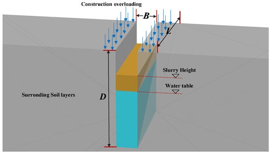
Figure 1.
Cross-sectional schematic of the diaphragm wall trench.
2.2. Theoretical Model of Global Instability
2.2.1. Basic Assumptions and Simplifications
In contrast to the limit equilibrium approach grounded in Rankine’s earth pressure theory, the sliding mass model based on the Coulomb theory is more prevalently utilized for assessing the global stability of diaphragm walls in contemporary engineering practices, as cited in []. Coulomb’s methodology is predicated on two primary assumptions: firstly, the sliding mass is treated as a solid, un-distortable entity, and secondly, the failure plane is assumed to be a predetermined and simplistic plane or surface. For practical purposes, the sliding surface is commonly approximated as planar to ease computational complexity. Field evidence supports that when both the angle of incline at the wall’s rear side is less than 15 degrees and the friction angle between the wall’s back and the adjacent soil also falls below 15 degrees, it is reasonable to model the slide surface of the soil as planar. This approach keeps the calculation of active earth pressure within a tolerable error margin, ranging from 2% to 10%, as referenced in []. In this context, the slurry-saturated trench can be analogously represented as a vertical and sleek retaining structure, with the soil plane behind this simulated wall lying horizontally, thus complying with the presupposition of a plane sliding surface condition. To expedite the modeling and theoretical deduction, the subsequent assumptions and simplifications are proposed in light of the aforementioned criteria:
- (1)
- The entire sliding body is conceptualized as a rigid block, discounting any internal deformation during the analytical processes.
- (2)
- The potential failure plane is designated as an inclined planar surface.
- (3)
- A weighted average method is applied to assimilate multilayer soil strata into a uniform composite material.
2.2.2. Sliding Body Modeling for Overall Destruction of Trench Wall
Building upon the aforementioned presumptions and simplifications, a sliding mass model has been developed to analyze the overall sidewall instability of the trench, as depicted in Figure 2. The model bifurcates into scenario (a) and scenario (b), based on the relationship between the groundwater table and the height of the tension crack zone (Zc). Within the confines of Figure 2, L denotes the length of an individual diaphragm wall panel; H and B symbolize the depth and width of the sliding mass, in that order; while θ represents the angle of inclination of the sliding surface relative to the horizontal.
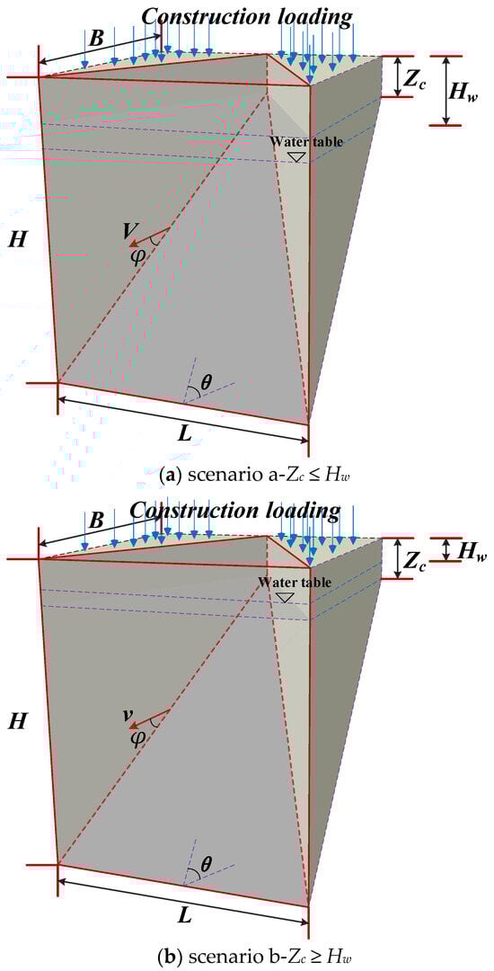
Figure 2.
Model of sliding mass for total failure analysis of the trench.
Guided by the principles of plastic limit state failure, the value of θ has been adopted as 45° plus φ/2, where φ symbolizes the average soil internal friction angle. Hs signifies the vertical span from the slurry’s surface to the earth’s surface, and Hw measures the vertical distance from the water table to the ground surface. The vector v defines the velocity of the entire sliding mass. It is assumed that the soil adheres to an associative flow rule, meaning that the angle between vector v and the sliding plane is equal to φ, the aforementioned average internal friction angle of the soil.
2.2.3. Derivation of Calculation Equation for Mud Weight during Trenching Construction
Considering scenario (a) depicted in Figure 2, a mechanical analysis can be constructed by projecting the sliding mass along the longitudinal axis of the trench. Figure 3 presents this analysis, articulating the actual forces exerted on the trench walls and the principles of static equilibrium. In Figure 3:
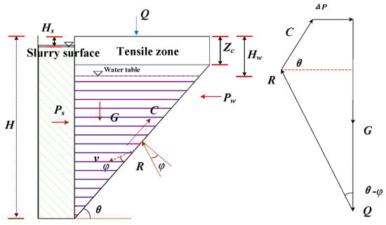
Figure 3.
Schematic of limit equilibrium analysis for the sliding body model in overall failure of the trench.
G represents the self-weight of the sliding mass.
Q is the cumulative force resultant from a uniformly distributed load q around the trench wall.
R stands for the reaction force exerted by the soil on the sliding plane.
Pw is the net force of hydrostatic pressure acting upon the trench wall.
Ps denotes the lateral force resultant generated by the pressure of the slurry within the trench acting against the sliding wall.
ΔP indicates the differential between Ps and Pw.
C is the cohesive force resultant along the two vertical extremities of the sliding mass.
The detailed derivation begins with the following:
- (1)
- Determine , the power generated by the dead weight of sliding body G.
The detailed derivation begins with the following: Given groundwater’s presence, the gravitational mass of the slide body must be calculated by distinguishing between the segments above and below the water table line. Consequently, the total weight of the sliding mass G can be delineated as:
where γ is the average weight of soil above the water table, γ′ is the average effective weight of soil below the water table, V1 is the volume of sliding body above the water table, and V2 is the volume of sliding body below the water table. V1 and V2 are calculated according to Equation (2).
G = γV1 + γ′V2
In Equation (2), , where c is the average cohesion of the soil layer and Ka is the active earth pressure coefficient, which equals tan2 (45° − φ/2).
Finally, the power generated from the dead weight of a sliding body can be calculated as follows:
- (2)
- Determine , the power generated by resultant of the uniform load around the trench wall. The resultant of the uniform load around the trench wall, denoted as “Q”, can be calculated as follows:
Q = 12qL(H − Zc)cotθ
Therefore, was obtained as:
- (3)
- Determine the dissipative power generated by the pressure difference between the slurry and groundwater. The pressure difference between slurry and groundwater (ΔP) on the side wall is:where γs is the weight of the slurry in the trench and γw is the weight of the groundwater. The dissipative power generated by the pressure difference ΔP can then be calculated as:
WΔP = ΔPvcos(θ − φ)
- (4)
- Determine the power generated by the reaction force of soil acting on the sliding surface. Using the force vector polygon calculation shown in Figure 3, the power generated by the soil’s reaction force on the sliding surface can be calculated as:
Meanwhile, the dissipative power of R can be calculated as:
From Equations (8) and (9), it can be inferred that the power and the dissipative power produced by the soil reaction force on the sliding surface are equal in magnitude. Consequently, in terms of power acting upon the system, the effects of the soil reaction force on the sliding surface can be considered to cancel each other out.
- (5)
- Determine the dissipative power generated by the resultant cohesive force on the two vertical sides of the sliding body (denoted as C). Firstly, calculate the resultant cohesive force on the two vertical sides of the sliding body as follows:
C = 2cSside
Then, the dissipative power produced by the resultant caused by cohesion on two vertical sides of the sliding body can be obtained:
- (6)
- The slurry weight is calculated by employing the principle of virtual work and the theory of limit equilibrium, whereby the mechanical equation of the sliding body in a state of limit equilibrium can be formulated as = , where and are calculated according to Equation (13).
Through theoretical derivation, the formula for calculating the minimum required slurry weight for diaphragm wall trenching operations can be established as follows:
According to Equation (14), the slurry weight, denoted by γs, is contingent upon various factors: the length of excavation section L, sliding body depth H, distance from groundwater level to the ground surface height Hw, slurry surface to the ground surface height Hs, the angle (θ) between the inclined sliding surface and horizontal plane, and soil shear strength parameters (c and φ). In a specific engineering project, these physical parameters can be ascertained from the geological survey and the corresponding design documents, enabling the straightforward calculation of the requisite slurry weight γs to guarantee the trench wall’s overall stability. For scenario (b), depicted in Figure 2, changes in the water table may alter the weight of the sliding body and the underground hydrostatic pressure. Nonetheless, the derivation process above remains applicable and is not reiterated here for brevity.
- (7)
- To determine the overall safety factor of the trench wall, it is common practice to incorporate safety margins to ensure the security of trench construction operations. Derived from the limit equilibrium equations previously discussed, the safety factor can be expressed as the ratio of the dissipative power that resists the overall sliding failure of the trench wall to the power of the external forces that promote the overall sliding failure of the trench wall. This ratio is detailed in Equation (15).
To ensure adequate safety, the design value for the slurry weight, denoted by the symbol γs, should include the safety factor, Fs. This adjusted slurry weight is calculated and referred to as the mud weight for engineering purposes.
In conclusion, the factor of safety (Fs) for trench wall stability can be computed with Equation (15) once the slurry weight (γs) is provided. This allows for an evaluation of the trench wall’s stability. Alternatively, the required slurry weight (γs) can be determined by applying Equation (16) with a predefined factor of safety (Fs), ensuring adherence to safety criteria.
2.3. Parameter Sensitivity Analysis of the Overall Stability of the Trench Wall
The factor of safety (Fs) serves as a critical metric for assessing the stability of trench walls. Under typical conditions, a value for Fs greater than 1 indicates stability, while a value less than 1 signifies instability and a value equal to 1 points to a state of incipient failure or limit equilibrium. This paper focuses on the prevalent computational approach for determining Fs, particularly regarding the three-dimensional global stability of trench walls, and compares it to established standards in engineering design. This method was selected for its widespread recognition and usage, providing a baseline for professional discourse while maintaining clarity and simplicity in its grammatical construction.
Fs = (Ps − Pw)/P
The fundamental parameters for the calculation were as follows: γ = 18 kN/m3, γ′ = 9 kN/m3, γw = 9.8 kN/m3, γs = 11 kN/m3, q = 0 kPa, c = 0 kPa, φ = 20°, L = 5 m, H = 20 m, Hs = 0 m, Hw = 2 m. Subsequently, the impact on the safety factor, Fs, was determined by varying each parameter independently, maintaining the constancy of the others. The outcomes of this analysis are depicted in Figure 4, Figure 5, Figure 6 and Figure 7.
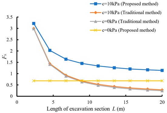
Figure 4.
Curves of the relationship between safety factor and trench length.
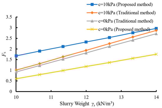
Figure 5.
Curves of the relationship between safety factor and mud weight.
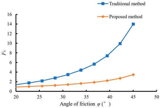
Figure 6.
Curves of the relationship between safety factor and internal friction angle of soil.
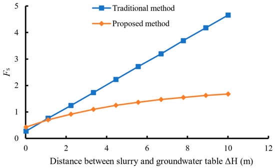
Figure 7.
Curves of the relationship between safety factor and the relative height difference between the mud and water level.
As illustrated by Figure 4, the curve reveals the impact of trench section length (L) on the Fs across different soil types. In the case of cohesive soil with a cohesion (c) of 10 kPa, both methods yielded similar outcomes: Fs decreases nonlinearly as L increases, which is evidently illogical. Conversely, with the suggested method, Fs appropriately decreases nonlinearly with increasing L, aligning with theoretical expectations. Figure 5 depicts the correlation between Fs and γs for both methods, where Fs is shown to increase linearly with γs under all conditions. An analysis of the patterns in Figure 4 and Figure 5 allows for the conclusion that the method put forth in this study presents increased sensitivity to soil cohesion. The conventional method, by applying an equivalent internal friction angle, translates cohesive soil conditions to those analogous to cohesionless soils, thus diminishing the influence of cohesive forces on the vertical sliding body boundary. This is substantiated by literature [], which has confirmed that the values of Fs calculated with full consideration of the cohesive forces on the vertical sliding plane are significantly higher, confirming the superiority of the method proposed in this research for the stability assessment of trench walls in clay layers over traditional approaches. Further discussions in this section indicate that for cohesionless soils, such as saturated sandy soils, extensive trench sections necessitate stability assurance measures, including the augmentation of slurry weight, construction of tall guide walls, raising of the slurry level, and reinforcement of the trench wall’s soil body.
As depicted in Figure 6, the safety factor (Fs) generated via both evaluated methods exhibits a nonlinear increment as the internal friction angle (φ) of the soil layer increases. The outcomes derived from the traditional method are consistently higher than those from the proposed method across various values of φ. Consequently, applying the traditional method to soils with a high internal friction angle results in the calculation of a larger necessary slurry weight, leading to a more conservative design approach in construction.
Figure 7 reveals that the Fs values calculated by the two methods follow different trajectories of growth as the relative height difference (ΔH) between the slurry level and the water table increases. However, both methods yield an Fs value of less than 1 when the slurry level is equivalent to the water table, suggesting an inherent instability of the trench wall. For practical construction applications, the slurry level is generally maintained 0.5 m above the water table; nevertheless, the exact height difference should be tailored to the specific conditions of the construction environment.
3. Engineering Case Study
3.1. Overview of the Project
The Baiyun Comprehensive Transportation Hub Station foundation pit project is located in Guangzhou, China, positioned adjacent to the east side of the existing Beijing–Guangzhou Railway and the west side of Tangxin Road in Xinshi Street. This station’s central section intersects with the Changsheng International Business Park, serving as a pivotal interchange hub for five subway lines, which include two east–west and three north–south lines. Given the multifaceted construction environment and the considerable operational complexity, the implementation of diaphragm walls has been chosen as the primary method for foundation support. This strategic decision aims to mitigate risks of uneven surface settlement that could inflict damage on adjacent structures, especially crucial during the construction of the extensive subway network. The surrounding ongoing construction projects and the restricted spatial allowance at the site further accentuate the complexity by exerting a concentrated load on the ground. Such conditions heighten the risk of sidewall collapse and other construction-related hazards during the trench excavation for the diaphragm wall system.
Moreover, the enclosing urban infrastructure and the high-density traffic environment necessitate meticulous planning to prevent any adverse impacts on the existing railway and road networks. This setting requires an adept integration of geotechnical engineering principles to manage the soil–structure interaction effectively. To compound the challenge, the substantial scale of this construction project exerts a profound influence on the overall engineering costs through the design and execution of trenching operations. Therefore, determining an optimal trenching slurry weight becomes instrumental. Appropriate slurry density not only fortifies the trench walls against collapse and excessive deformation, but also ensures minimal disruption to the existing infrastructural framework. Careful consideration and selection of the slurry properties are paramount to preserving construction safety and stability. Additionally, optimizing slurry characteristics contributes significantly to the efficient management of construction expenses. These parameters are meticulously governed through thorough soil analysis and iterative design adjustments, ensuring both safety and cost-efficiency are upheld through the construction process.
By harnessing advanced engineering methodologies and adhering to rigorous safety standards, the Baiyun Comprehensive Transportation Hub Station project exemplifies the critical balance between innovative engineering solutions and practical financial considerations, underscoring the importance of detailed planning and precise execution in complex urban construction environments.
3.2. Values of Relevant Parameters
The following relevant design parameters have been rigorously determined through an extensive engineering geological investigation and detailed design documentation, forming the basis for a comprehensive stability analysis of the diaphragm wall trenching construction project:
Diaphragm wall segment length (L): Each segment of the diaphragm wall is designed with a length of 6 m. This dimension is critical as it influences the overall stability and flexibility of the wall under various loading conditions.
Distance from ground surface to groundwater level (Hw): The groundwater level is situated 8 m below the ground surface. This parameter is significant in determining the hydrostatic pressure exerted on the trench walls, which affects the wall’s stability and the necessary construction precautions.
Average density of groundwater (γw): The groundwater density is calculated to be 9.8 kN/m3. This average density is used to estimate the buoyant forces and potential uplift pressures against the wall structure.
Depth from trench’s slurry surface to ground surface (Hs): The depth from the slurry-filled trench surface to the ground surface is 2 m. This depth is a crucial factor in assessing the trench stability during the construction phase, as it influences the lateral earth pressures and potential for trench collapse.
Average density of soil layer (γ): Soil density is averaged at 18.58 kN/m3. This parameter is critical for calculating the earth pressures acting on the diaphragm wall, contributing to the overall forces that need to be countered during construction.
Average cohesion (c) of soil layer: Soil cohesion is averaged at 20.46 kPa. This measure of soil shear strength is key in understanding the soil’s ability to resist shearing stresses, which impacts the stability and design of the diaphragm wall.
Angle of internal friction (φ): The internal friction angle for the soil layer is averaged at 20.47°. This angle is crucial in evaluating the soil shear strength and the stability of the wall against sliding or rotational failure.
Uniform construction overload (q): A uniform construction overload of 40 kPa is considered around the trench wall. This overload represents the additional load from construction equipment and materials, which needs to be factored into the stability analysis to ensure an adequate safety margin.
These meticulously gathered and calculated parameters provide a solid technical foundation for the subsequent analytical discourse in the paper, underpinning the entire stability analysis and justifying the engineering solutions proposed for the project’s successful execution.
3.3. Comparative Analysis of the Theoretical Calculation Range and Measured Value of Slurry Weight
In practical engineering applications, consideration of safety stock is paramount, particularly in relation to slurry weight during the construction of diaphragm walls. The safety factor (Fs) may vary depending on whether the length of the trench section and the cohesive strength acting on the vertical face of the potential sliding mass are factored into the calculations. According to established literature, an Fs greater than 1.5 is recommended when these two factors are not taken into account. However, when the length of the trench section is considered, some studies propose that an Fs value of 1.6 may still be conservative, potentially overlooking other critical aspects of trench stability.
In this study, both the trench length and cohesive strength are incorporated into the computational model, setting the safety factor between 1.8 and 2.0. This heightened safety factor aims to provide a buffer against unforeseen conditions and variations in soil properties, offering greater assurance of trench stability. The slurry weight is a vital parameter in ensuring the trench wall’s stability against sliding. To this end, the slurry weight range corresponding to the overall trench wall sliding instability model developed in this study is calculated using Equation (16). This approach contrasts with traditional methodologies, which have yielded somewhat different slurry weight ranges. Specifically, the newly proposed method indicates a slurry weight range between 9.91 and 10.84 kN/m3, whereas the traditional approach suggests a range between 10.18 and 11.43 kN/m3.
The slightly lower slurry weight range in the newly proposed method may indicate increased efficiency and potentially lower material costs, without compromising safety. Moreover, this optimized range helps minimize risks associated with overburden pressure and lateral movements in the trench walls.
To further substantiate the findings, five representative trench segments were meticulously selected for assessment. These segments were chosen based on depth and structural complexity, ensuring a comprehensive evaluation across various conditions. The variations in slurry weight and its implications on trench stability were meticulously analyzed, revealing key insights into the interplay between trench depth, construction difficulty, and slurry consistency.
The detailed findings from these assessments are visually represented in Figure 8 and Figure 9, highlighting the practical applicability and effectiveness of the proposed method over traditional techniques. These figures underscore the importance of adapting slurry weight based on specific geotechnical conditions and reinforce the study’s contributions to advancing safer and more efficient diaphragm wall construction practices.

Figure 8.
Engineering rendering.
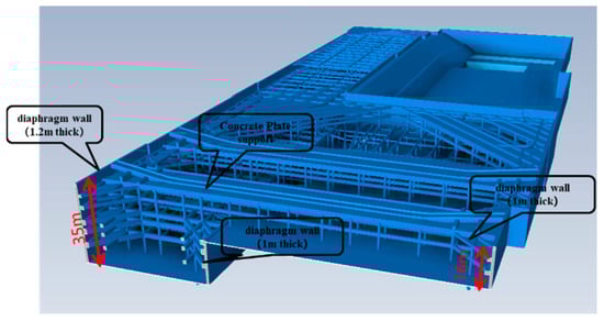
Figure 9.
Diaphragm wall support design.
Upon analyzing results depicted in Figure 8 and Figure 10, it has been observed that the minimum slurry weights for the five assessed segments fall within the calculated ranges predicted by both the proposed and traditional methods. This consistency indicates that both methods are viable under various conditions. However, a closer look at the average values reveals a notable difference: the proposed method yields an average slurry weight of 10.38 kN/m3, whereas the traditional method gives an average of 10.8 kN/m3. The slurry weight derived from the proposed method aligns more closely with the actual measured slurry weight.
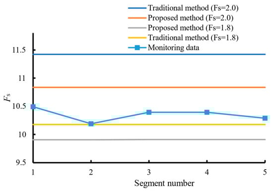
Figure 10.
Comparison between theoretical calculation values and measured values of mud weight.
This closer alignment suggests that the proposed method offers improved precision in estimating slurry weights, which is critical for maintaining the stability of diaphragm wall trenching construction. A more accurate slurry weight calculation directly impacts the balance of pressures within the trench, reducing the risk of trench collapse and improving overall safety. Furthermore, the proposed method’s ability to predict slurry weights more precisely can lead to optimized material usage, which not only enhances safety margins but also contributes to cost-effectiveness in construction projects. Therefore, the findings support the adoption of the proposed method for more reliable and safer diaphragm wall trenching practices.
4. Conclusions and Limitations
The research established a sliding body model to analyze trench wall failures for underground diaphragm walls, integrating soil mass flow correlation law and plastic limit damage theory. This model employed a limit equilibrium approach to derive a calculation formula for mud weight and the safety coefficient of trench wall stability.
Key findings include:
The proposed method for calculating the trench wall’s overall stability safety factor is theoretically plausible and correlates well with increases in mud weight, soil internal friction angle, and elevation difference between the mud surface and the water table, enhancing the safety factor.
The approach effectively accounts for soil cohesion, making it particularly suitable for trench wall stability analysis in clay strata.
Recommendations based on the findings are:
Minimize the interval between trenching operations and ensure prompt lifting of reinforcement cages and concrete pouring to maintain stability.
Prioritize increasing slurry levels over mud weight to significantly improve the stability of shallow soil layers, especially in complex environments.
Focus reinforcement efforts on the trench wall’s shallow central soil zone, identified as more prone to destabilization.
Warnings to avoid work disturbances during trenching include:
Avoid stacking loads and heavy vehicle movements around the excavated section to reduce deformation and slow the rate of stability reduction.
However, the study acknowledges limitations:
Neglect of soil creep and its long-term impacts on soil properties and internal forces.
Assumptions about inclined linear failure planes and uniform soil strata, which may not accurately reflect real-world conditions.
These insights offer valuable theoretical guidance for designing mud weight in diaphragm wall trenches and emphasize the need to consider temporal soil changes and non-uniform soil composition in future research.
Author Contributions
Conceptualization, Z.L.; Methodology, J.L.; Software, M.L.; Validation, W.M.; Investigation, R.W.; Writing—original draft, Y.M.; Supervision, D.Z.; Funding acquisition, W.L. All authors have read and agreed to the published version of the manuscript.
Funding
This research was funded by the National Natural Science Foundation of China (Grant No. 52178302), Research and Development Project of the Ministry of Housing and Urban–Rural Development (Grant No. 2022-K-044), and the Natural Science Basic Research Program of Shaanxi [grant number 2022JQ-375].
Data Availability Statement
The original contributions presented in the study are included in the article, further inquiries can be directed to the corresponding author.
Conflicts of Interest
Author Zhicheng Liu was employed by the company Guangzhou Metro Group Co., Ltd. Authors Jianmei Liu, Muyu Li, Wufeng Mao and Ran Wang were employed by the company Guangzhou Metro Design and Research Institute Co., Ltd. Author Wenzhan Liu was employed by the company China Construction Second Engineering Bureau Co., Ltd. The remaining authors declare that the research was conducted in the absence of any commercial or financial relationships that could be construed as a potential conflict of interest.
References
- Saadi, R.; Baheddi, M.; Ferhoune, N. Analytical Approach of the Arching Dual Effect Describing the Stability of Slurry-Wall Trenches in Cohesionless Soil. Int. J. Geomech. 2017, 17, 04017081. [Google Scholar] [CrossRef]
- Jin, Y.-B. A method for determination of reinforcement width and depth of trench face of diaphragm wall. Yantu Lixue/Rock Soil Mech. 2017, 38, 273–278. [Google Scholar]
- Huang, F.; Wang, Z.; Luo, Y.; Zhou, H. Stability analysis of slurry trench based on nonlinear failure criterion and energy consumption analysis method. J. Railw. Sci. Eng. 2022, 19, 491–499. [Google Scholar]
- Castaldo, P.; Jalayer, F.; Palazzo, B. Probabilistic Assessment of Groundwater Leakage in Diaphragm Wall Joints for Deep Excavations. Tunn. Undergr. Space Technol. 2018, 71, 531–543. [Google Scholar] [CrossRef]
- Jin, Y.-B. Study of stability calculation method of trench face reinforcement of diaphragm wall. Yantu Lixue/Rock Soil Mech. 2017, 38, 305–312,350. [Google Scholar]
- Mingfeng, L.; Yao, L.; Chengyong, C. Design Method of Slurry Volume–Weight in Trenching Construction of Underground Diaphragm Wall in Soft Stratum. Geotech. Geol. Eng. 2017, 35, 2697–2704. [Google Scholar] [CrossRef]
- Qiu, M.; Yang, G.; Shen, Q.; Duan, J.; Zhang, P. Study on characteristics and influence factors of slurry trench stability of diaphragm wall in deep sandy stratum. J. Railw. Sci. Eng. 2020, 17, 1129–1139. [Google Scholar]
- Tong, L.; Guo, Q.; Che, H.; Zhang, M.; Pan, H.; Li, H. Investigation of Rebar Exposure Issues of Diaphragm Wall and Influencing Factors Analysis. KSCE J. Civ. Eng. 2019, 23, 1522–1536. [Google Scholar] [CrossRef]
- Solsky, S.V.; Sobkalov, F.P. Improvement of the Work Technology in the Construction of Impervious Barriers Using the Diaphragm Wall Method. Power Technol. Eng. 2022, 56, 358–362. [Google Scholar] [CrossRef]
- Chen, K.; Qiu, T.; Chen, X.; Wang, L.; Huang, J.; Su, D.; Lai, Y.; Li, A.; Zhang, J. Evaluating the GHG Reduction Efficiency of Underground Construction Technology: Application of a Novel Prefabricated Diaphragm Wall Technology. J. Clean. Prod. 2024, 450, 141926. [Google Scholar] [CrossRef]
- Lim, A.; Ou, C.-Y.; Hsieh, P.-G. An Innovative Earth Retaining Supported System for Deep Excavation. Comput. Geotech. 2019, 114, 103135. [Google Scholar] [CrossRef]
- Dai, Q.; Li, Z. Long-Term Mechanical Performance of Geothermal Diaphragm Walls in Stiff Clay. Tunn. Undergr. Space Technol. 2019, 94, 103113. [Google Scholar] [CrossRef]
- Wang, H.; Huang, M. Upper Bound Stability Analysis of Slurry-Supported Trenches in Layered Soils. Comput. Geotech. 2020, 122, 103554. [Google Scholar] [CrossRef]
- Qin, C. Determination of Slurry Density Required for Stability of Slurry-Supported Trenches Excavated in Partially Submerged Soils. Comput. Geotech. 2019, 116, 103212. [Google Scholar] [CrossRef]
- Huang, X.; Li, J.; Xue, Q.; Chen, Z.; Du, Y.; Wan, Y.; Liu, L.; Poon, C.S. Use of Self-Hardening Slurry for Trench Cutoff Wall: A Review. Constr. Build. Mater. 2021, 286, 122959. [Google Scholar] [CrossRef]
- Kmeid, M.; Casaux-Ginestet, G.; Escadeillas, G.; Armengaud, J.; Robit, P. Shadowing Pathology on Diaphragm Walls Investigation. Constr. Build. Mater. 2023, 408, 133719. [Google Scholar] [CrossRef]
- Pan, Y.; Fu, Y. Effect of Random Geometric Imperfections on the Water-Tightness of Diaphragm Wall. J. Hydrol. 2020, 580, 124252. [Google Scholar] [CrossRef]
- Tu, S.; Li, W.; Zhang, C.; Wang, L.; Wang, S.; Zhao, Y.; Wu, J. Face Stability Analysis of Tunnels in Saturated Soil Considering Soil-Fluid Coupling Effect via Material Point Method. Comput. Geotech. 2023, 161, 105592. [Google Scholar] [CrossRef]
- Zizka, Z.; Schoesser, B.; Thewes, M. Investigations on the Transient Support Pressure Transfer at the Tunnel Face during Slurry Shield Drive Part 2: Case B—Deep Slurry Penetration Exceeds Tool Cutting Depth. Tunn. Undergr. Space Technol. 2021, 118, 104169. [Google Scholar] [CrossRef]
- Zhong, Y.; Bidarmaghz, A.; Narsilio, G.A.; Makasis, N. Thermo-Hydraulic Analysis in Geothermal Energy Walls. Tunn. Undergr. Space Technol. 2023, 132, 104862. [Google Scholar] [CrossRef]
- Makasis, N.; Narsilio, G.A. Energy Diaphragm Wall Thermal Design: The Effects of Pipe Configuration and Spacing. Renew. Energy 2020, 154, 476–487. [Google Scholar] [CrossRef]
- Yao, C.; Yan, Q.; Sun, M.; Dong, W.; Guo, D. Rigid Diaphragm Wall with a Relief Shelf to Mitigate the Deformations of Soil and Shallow Foundations Subjected to Normal Faulting. Soil Dyn. Earthq. Eng. 2020, 137, 106264. [Google Scholar] [CrossRef]
- Yang, Y.-L.; Reddy, K.R.; Zhang, T.; Fan, R.-D.; Fu, X.-L.; Du, Y.-J. Enhanced Contaminant Retardation by Novel Modified Calcium Bentonite Backfill in Slurry Trench Cutoff Walls. Constr. Build. Mater. 2022, 320, 126285. [Google Scholar] [CrossRef]
Disclaimer/Publisher’s Note: The statements, opinions and data contained in all publications are solely those of the individual author(s) and contributor(s) and not of MDPI and/or the editor(s). MDPI and/or the editor(s) disclaim responsibility for any injury to people or property resulting from any ideas, methods, instructions or products referred to in the content. |
© 2024 by the authors. Licensee MDPI, Basel, Switzerland. This article is an open access article distributed under the terms and conditions of the Creative Commons Attribution (CC BY) license (https://creativecommons.org/licenses/by/4.0/).