Article

Numerical Simulation Study on Evolution Process of Carrying-Soil Effect of Rectangular Pipe Jacking

Faculty of Engineering, China University of Geosciences (Wuhan), No. 388 Lumo Road, Wuhan 430079, China
*
Author to whom correspondence should be addressed.
Buildings 2024, 14(10), 3057; https://doi.org/10.3390/buildings14103057
Submission received: 4 August 2024 / Revised: 19 September 2024 / Accepted: 22 September 2024 / Published: 25 September 2024
(This article belongs to the Section Building Energy, Physics, Environment, and Systems)

Abstract

:
The carrying-soil effect is an important factor affecting the success or failure of rectangular pipe jacking construction. Because it is difficult to explore the dynamic evolution process of the carrying-soil effect in the field test, this paper relies on the pipe jacking project of a comprehensive pipe gallery in Suzhou City, and uses ABAQUS 2021 finite element software to simulate the jacking process of rectangular pipe jacking. Based on the theory of plastic mechanics of rock and soil and the related research and application status, the equivalent plastic strain index is introduced as the basis for judging the failure boundary of soil in the numerical simulation results, and the boundary between the carrying-soil area and the surrounding soil is determined, that is, the shear fracture surface. According to the principle of plastic potential energy, the development direction of the fracture surface is consistent with the direction of plastic flow, so as to predict the development direction of the boundary of the carrying-soil area. According to the change in the equivalent plastic strain cloud map with the jacking mileage, the evolution process of the carrying-soil effect is clarified, and the dynamic evolution law of the carrying-soil area is revealed, which is of great significance for predicting the disturbance of the surrounding soil during the construction of rectangular pipe jacking and accurately evaluating the environmental effect of the construction.

1. Introduction

With the acceleration of urbanization in China, the demand for urban underground space development has gradually increased. Rectangular pipe jacking construction technology, as a kind of trenchless technology, has gradually become one of the widely used technologies in urban underground engineering with its technical and economic advantages such as less disturbance, high efficiency, and high utilization rate [1]. At present, domestic and foreign scholars [2,3,4,5,6] have conducted in-depth research on rectangular pipe jacking, accumulated many effective research methods, and formed rich research results. However, in the construction of rectangular pipe jacking, it is inevitable to disturb the surrounding strata; especially in rectangular pipe jacking projects under certain conditions such as large sections, long distances, and shallow overburden, the carrying-soil effect can easily appear, causing surface deformation, destroying ground structures and underground pipelines, and even leading to ground collapse, endangering the safety of life and property. Therefore, determining the evolution process of the carrying-soil effect is of great significance for predicting the disturbance of the surrounding soil during the construction of rectangular pipe jacking and accurately evaluating the environmental effect of pipe jacking construction.
To date, domestic and foreign scholars have conducted comprehensive and in-depth studies on the carrying-soil effect of rectangular pipe jacking, accumulated many effective research methods, and obtained rich research results. Peng Limin [7] and Yu Binquan [8] defined the carrying-soil effect as follows: in the process of pipe jacking, the soil above the tunnel is disturbed and collapses on the top of the microtunnel boring machine so that the contact friction resistance increases, which hinders the smooth jacking of the pipe, and its reaction force will compress and deform the soil and carry it forward. Gao Yi et al. [9] defined the concept of overall carrying soil based on the previous overview of the carrying-soil effect. Based on the concept of the early carrying-soil effect, Ma Peng et al. [10] proposed that the carrying-soil effect is a phenomenon in which under the action of multiple factors, the surrounding soil locally or wholly collapses at the top or side of the pipe and migrates along with it, and finally produces a sudden increase in the jacking force and a sudden rise and fall of the surface. Based on the theory of the overall carrying-soil effect, Dou et al. [11] analyzed the causes of the overall carrying-soil effect in combination with their actual project, and proposed several specific measures to treat the overall carrying-soil effect. Based on the measured data of a shallow-buried rectangular pipe jacking project, Zhen Liang [12] et al. considered the friction difference between the microtunnel boring machine and the subsequent pipe and the soil, proposed a method for judging the overall carrying-soil effect, and calculated the critical friction coefficient between the pipe and soil as well as the lateral range and vertical uplift range of the carrying-soil effect. Gao [13] et al. used a numerical method to explore the inhibitory effect of setting isolation on the carrying-soil effect, and found that the greater the number of isolation wall groups set, the stronger the inhibition of the carrying-soil effect.
The existing literature on the dynamic evolution process of the carrying-soil effect is not in-depth enough, and the assumptions of the existing prediction models are too simplified. The relevant literature does not accurately define the area affected by the carrying-soil effect, and the influence range of the carrying-soil effect is still unclear, which makes the treatment measures after the carrying-soil phenomenon less effective. Because it is difficult to explore the dynamic evolution process of the carrying-soil effect in field tests, ABAQUS, as a finite element software for engineering simulation, can solve relatively simple linear problems and many complex nonlinear problems. Therefore, based on the pipe jacking project of the utility tunnel in Suzhou City, this paper uses ABAQUS finite element software to explore and analyze the evolution process of the carrying-soil effect of rectangular pipe jacking, and reveals the dynamic evolution law of the carrying-soil effect.

2. Establishment of Numerical Model

There are great differences in the construction technology between pipe jacking projects and conventional tunnel projects. The numerical method of conventional tunnel projects is no longer applicable in the numerical simulation of the pipe jacking project, and the pile sinking (mainly the static pressure pile and the driven pile) in the pile foundation project has many similarities with the characteristics of pipe jacking construction, so we can refer to the relevant numerical methods of the pile sinking foundation for research. The arbitrary Lagrangian–Eulerian method (ALE method) [14] commonly used in the simulation analysis of the pile driving process by ABAQUS finite element software is selected to study the related problems.

2.1. Project Profile

The pipe jacking project of an underground comprehensive pipe gallery in Suzhou City has a total length of 233.6 m. A reinforced concrete rectangular pipe with a length of 2.5 m, a width of 9.1 m, a height of 5.5 m, and a thickness of 0.65 m is used. The average thickness of the pipe gallery is 9 m. The situation of pipe jacking through the stratum is shown in Figure 1.
Before pipe jacking, multiple vibrating wire pressure sensors are arranged on the prefabricated reinforced concrete rectangular pipe to monitor the load around the pipe. The layout points are shown in Figure 2. Among them, T1 and T5 are symmetrically arranged top measuring points with T4 as the axis; T2 and T3 are arranged adjacent to the top grouting hole to monitor the injection mud pressure; the L1~L3 measuring points are on the left wall; the measuring point R2 is at the same horizontal height as measuring point L2 on the right wall; and B1 and B2 are the bottom measuring points.

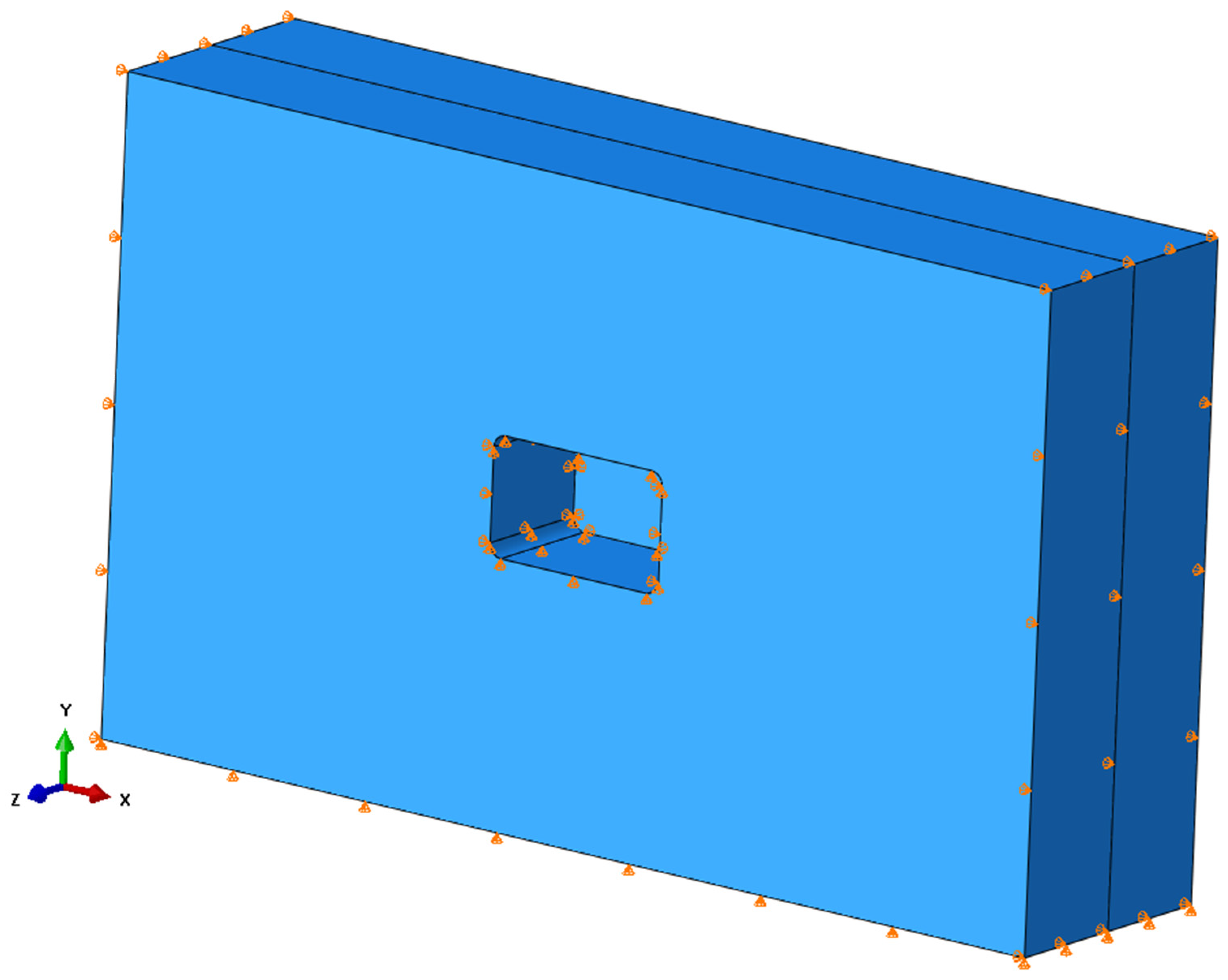
2.2. Basic Assumptions

When modeling the soil, the soil is assumed to be isotropic material and simplified as an ideal elastic–plastic material. We ignore the initial ground stress of the soil, regardless of groundwater disturbance to the soil, soil drainage consolidation, slurry seepage consolidation, and other factors.
The construction process of rectangular pipe jacking is regarded as continuous straight jacking, ignoring the dynamic effect of nonlinear changes in incremental step length on soil deformation, and ignoring the time effect of the jacking process.
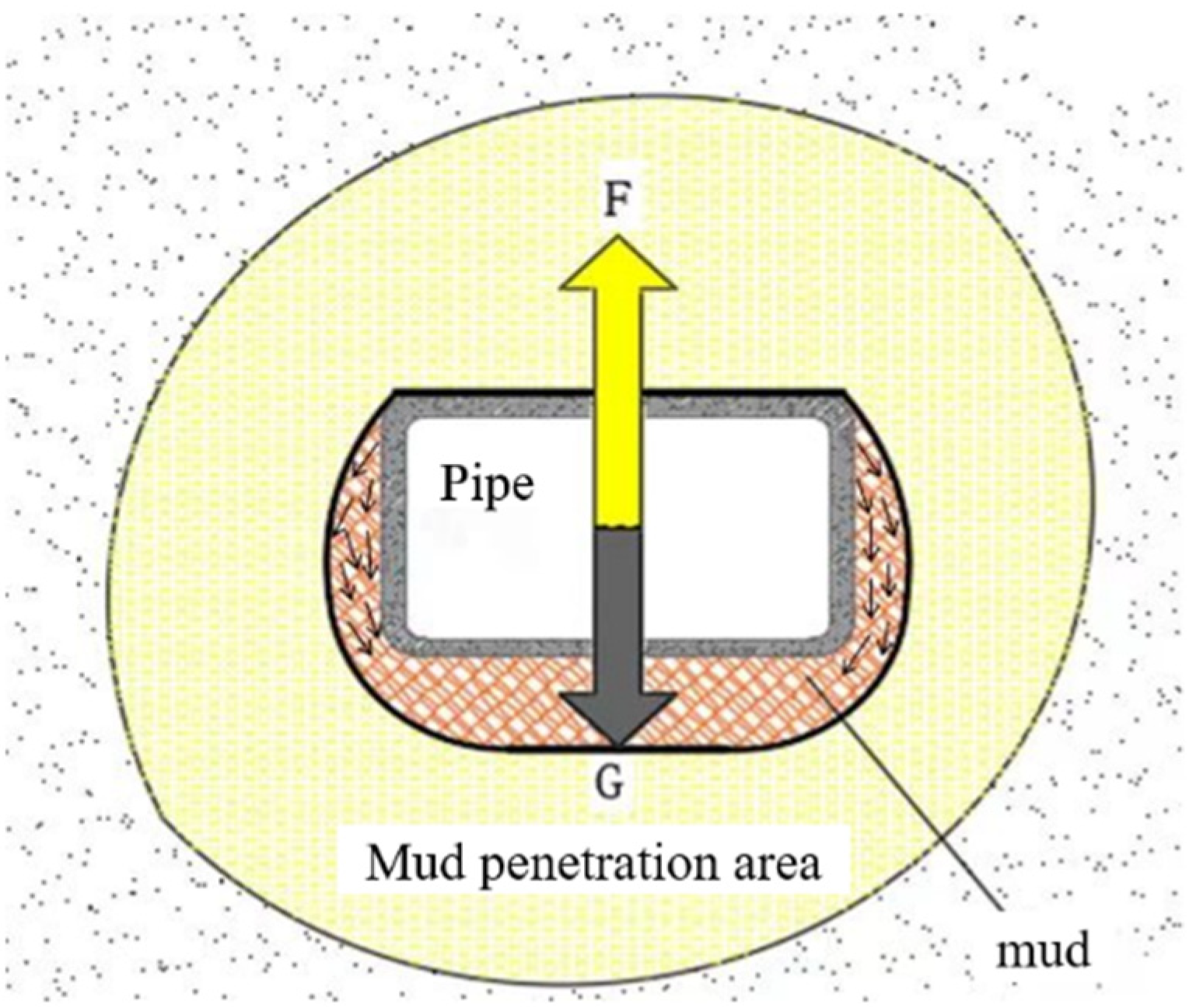
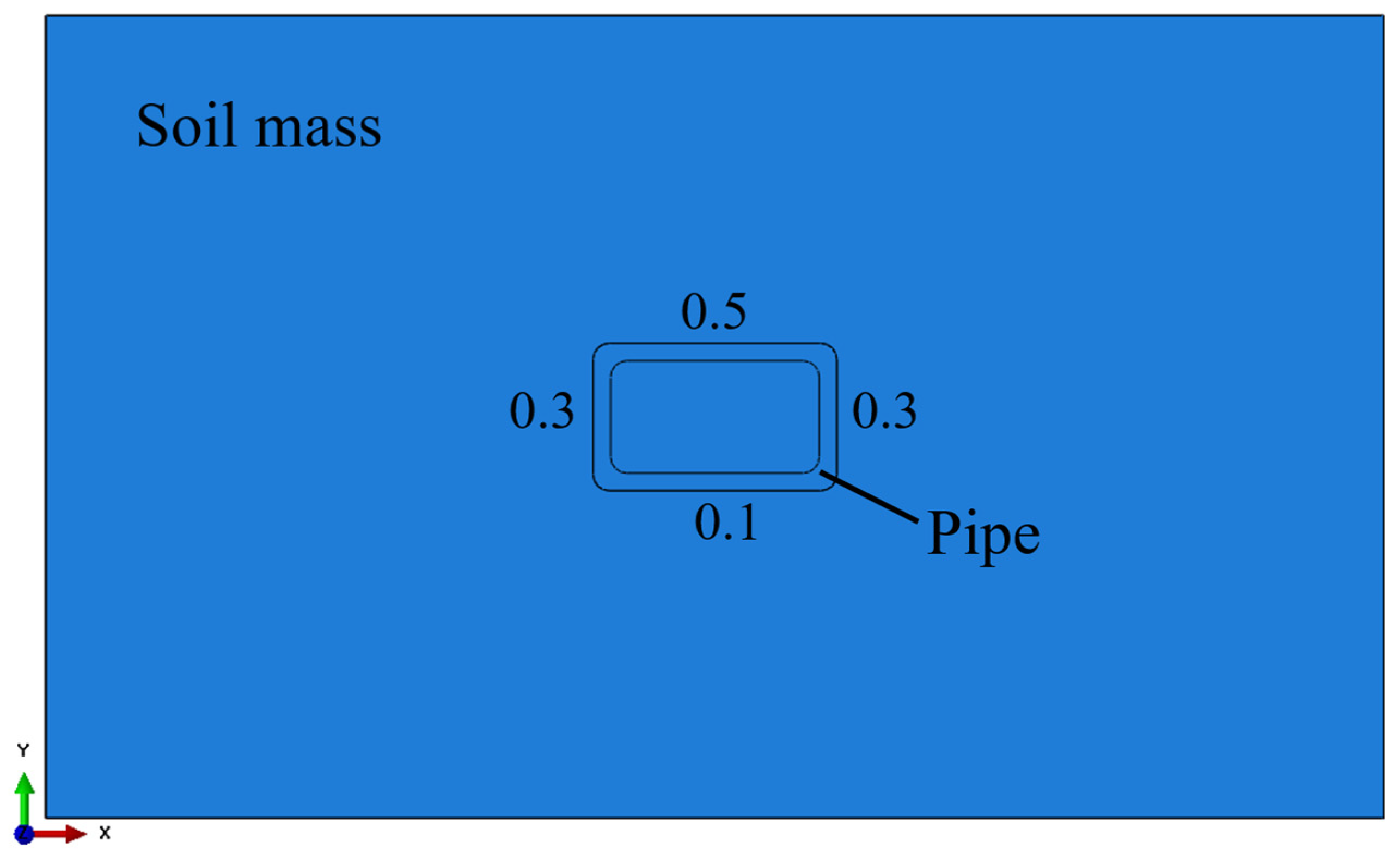
The contact state between the pipe and the borehole wall is as follows: the top of the pipe is in contact with the soil, the other three side walls are in contact with the mud, and the mud sleeve is in the shape of ‘U’, as shown in Figure 3. Assuming that the contact state of each pipe–soil contact surface is continuous, the top of the pipe is fully in contact with the soil, and the friction coefficient is 0.5. The bottom is pipe slurry contact, and the friction coefficient is 0.1. The contact state of the pipe and soil on the left and right sides gradually transitions from top to bottom, and the friction coefficient is 0.3.
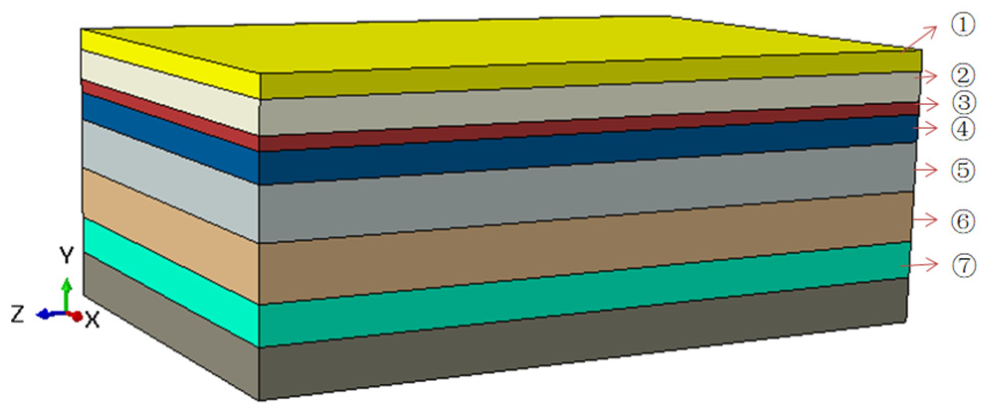
Ignoring the interbedded strata, the thickness of each layer of soil is taken as the average thickness. Reinforced concrete pipe is regarded as homogeneous elastic material.

2.3. Model Parameter Setting

Based on the above assumptions, the selection of model parameters is further specified. In order to ensure that the disturbance of the surrounding soil caused by the rectangular pipe jacking construction is fully reflected and the calculation time cost is the lowest, according to the actual size of the pipe jacking project of the utility tunnel in Suzhou, the size of the model stratum is determined to be 80 m long, 50 m wide and 30 m high. As shown in Figure 4, the material parameters of each layer of soil are attached according to Table 1.
The structure of the pipe and the size parameters of the microtunnel boring machine are input according to the actual size listed in Table 2. The modeling parts are shown in Figure 5, which stipulates that the jacking direction in the model is the negative direction of the coordinate axis z, and the same applies below.
The weight of reinforced concrete pipe is 25 KN/m3, the elastic modulus is 3.0 Gpa, and the Poisson’s ratio is 0.2. Based on the applicability of different constitutive models, the constitutive relation of reinforced concrete pipe is selected as isotropic linear elasticity. The soil is regarded as an ideal elastic–plastic material, and the linear elastic and Mohr–Coulomb models are selected for the elastic and plastic parts, respectively.
In order to simulate the semi-infinite space ground stress field of the pipe jacking construction stratum more realistically, the upper surface of the soil is set in two directions: free boundary and constrained bottom surface. The overall situation of the model boundary condition settings is shown in Figure 6.
In the process of mesh element division, the mesh elements of the soil around the pipe are encrypted, as shown in Figure 7. After meshing, the soil is divided into 57,876 units and the number of nodes is 61,692. The pipe and microtunnel boring machine are divided into 2388 units, and the number of nodes is 5642.

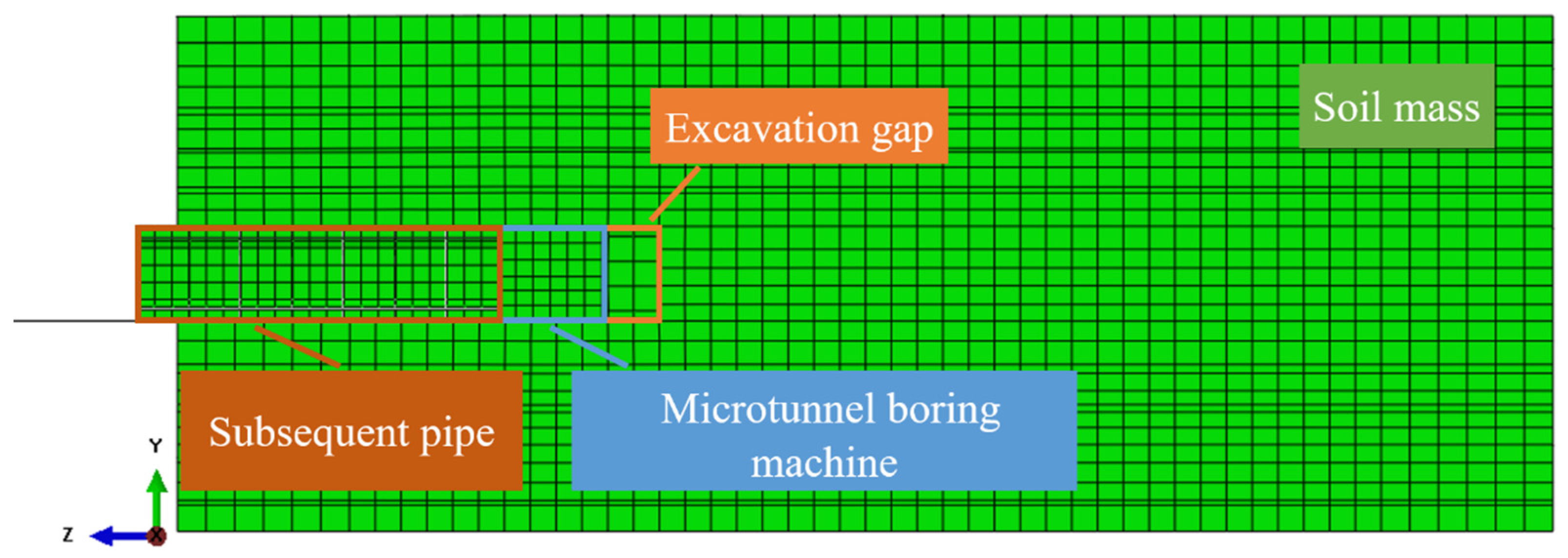
2.4. Simulation of Jacking Process

(1)
Construction Jacking Simulation
In this paper, the displacement control method is used to realize the overall forward jacking of the pipe and the microtunnel boring machine. The “killing” function of the “life and death unit method” is used to realize the working conditions of the cutter head cutting the soil in front of the well and discharging the well, and the “activation” function is used to realize the shutdown and pipe change working conditions. Considering various factors, the single jacking distance is set to be 2.5 m of the length of a pipe, that is, the single excavation length is 2.5 m. The analysis steps of the construction jacking simulation process are shown in Table 3.
(2)
Pipe–Slurry–Soil Contact Simulation
When modeling, the ‘normal behavior’ in the ‘interaction’ function of the software is set to ‘hard contact’, and different ‘penalty’ values are set in the ‘tangential behavior’, so as to realize the simulation of the contact condition of pipe–slurry–soil. As shown in Figure 8, the contact friction coefficients of each side between the pipe and the soil are set to 0.5, 0.3 and 0.1, respectively.
(3)
Supplementary Measures of Process Simulation
In theory, before the cutterhead is jacked into the new excavation face, as shown in Figure 9, the soil around the excavation gap will squeeze into the excavated space, and then change the stress and strain state of the surrounding soil, which is inconsistent with the actual situation. Therefore, this paper creates displacement boundary conditions to constrain the displacement of each side inside the excavation gap. As shown in Figure 10, the upper and lower parts of the internal space of the soil excavation only limit the displacement in the upper Y direction (gravity direction, the same below), the left and right sides only limit the displacement in the X direction (horizontal direction, the same below), and the newly formed excavation surface only limits the displacement in the Z direction (vertical horizontal direction, the same below), so as to realize the constraint on the displacement of the soil around the excavation gap.

2.5. Comparison and Verification of Measured Values and Simulated Values

In order to verify the rationality of the above assumptions, and the accuracy of theoretical derivation and numerical simulation, the measured value is compared with the normal load around the pipe obtained by numerical simulation.
The monitoring data of pipe pressure with little change in overburden depth and jacking direction mileage of K100 m~K130 m were selected. The average grouting pressure of two adjacent grouting intervals was taken as the grouting pressure value, and the average grouting pressure and the average soil pressure of multiple grouting cycles were used as the pipe pressure value of the monitoring section. The pressure values at the top and bottom of the pipe were 144.75 kPa and 136.4 kPa, respectively, and the pressures at the three measuring points on the side were 183.1 kPa, 145.4 kPa and 128.6 kPa, respectively.
The pressure value obtained by monitoring is regarded as the normal load around the pipe, and the numerical simulation results of the normal load around the pipe are extracted by the ‘Path’ data extraction method. The distribution of the normal load around the pipe obtained by the monitoring value, and the numerical simulation is shown in Figure 11.
It can be seen from Figure 11 that the comparison between the simulated and measured values of the normal load around the pipe is as follows: (1) At the top of the pipe, the normal load of the pipe obtained by the simulated calculation is almost equal to the measured value. (2) At the left side of the pipe, the normal load of the pipe obtained by the simulation calculation of the measuring point is consistent with the measured value. It is worth noting that the normal load obtained by the numerical simulation calculation shows a ‘wavy’ distribution, i.e., the normal load is small in the side wall of the pipe near the round chamfer, but it is larger in the middle of the side wall. It is speculated that the round chamfer of the pipe circumference will have a reaction force on the nearby soil, and the side soil is regarded as an ‘elastic–plastic simply supported beam’, as shown in Figure 12. Under the action of lateral horizontal earth pressure, the two ends (soil near the round chamfer) are ‘propped up’ to reduce the contact stress, and the middle soil is ‘squeezed’ to the side wall of the pipe, which increases the contact stress, so that the normal load on the side of the pipe presents a ‘wavy’ distribution. (3) At the bottom of the pipe, the simulated value is slightly larger than the measured value. Because the numerical model is a finite element model, there will be no soil loss in the actual construction during the jacking process. In the actual jacking process, the mud and the soil at the bottom may accumulate too thick at the bottom, form a large area of mud block, and attach to the bottom of the pipe so that the pressure at the bottom of the pipe measured by the earth pressure gauge is smaller than the actual value, so that the measured value of the normal load at the bottom of the pipe is less than the simulated value.
By comparing the normal load around the pipe obtained by numerical simulation with the measured value, it is found that the distribution law and change trend of the two are in good agreement, which proves the accuracy of the numerical model, and then the dynamic evolution law of the carrying-soil effect can be explored through the numerical model.

3. The Definition and Evolution Law of the Carrying-Soil Effect Area

3.1. The Definition of the Back-Soil Effect

Because the soil of this model is a Lagrangian solid, the soil element mesh cannot be split, and the numerical calculation has been interrupted due to non-convergence before the soil is destroyed, so it cannot directly reflect the shear slip surface between the soil in the carrying-soil area and the surrounding soil when the carrying-soil effect occurs. At this time, the definition basis is determined in the numerical simulation results by means of the plastic mechanics theory of rock and soil.
(1)
Theory of Plastic Mechanics of Rock and Soil Mass
Rock and soil mass is a kind of elastic–plastic solid. According to the theory of plastic mechanics, the plastic constitutive relationship is essentially an incremental relationship, that is, incremental theory or flow theory [15]. The theory holds that the ideal elastic–plastic material has the following relationship:
d λ = d ε x P S x = d ε y P S y = d ε z P S z = d ε x y P τ x y = d ε y z P τ y z = d ε z x P τ z x
In Formula (1), d λ is a scalar non-negative proportional constant, d ε i j P is the plastic strain increment in a certain direction of the stress space, and S i j and τ i j are the spatial stress deviator and shear stress deviator, respectively. The above formula shows that the plastic strain increment is only related to the stress deviation. The plastic flow rule can be obtained by relating the above relation to the yield condition.
In order to further study the development direction of plastic strain increment, plastic theory puts forward the theory and function of plastic potential energy. On the basis of the Drucker hypothesis (material stability hypothesis), it is proposed that the gradient direction of yield function in the direction of plastic strain increment vector is consistent:
g r a d ( f ) = 𝜕 f 𝜕 σ i j n
In Formula (2), f is the yield function of the yield surface, and n is the unit vector in the direction of the outer normal and the orthogonality between the plastic strain increment d ε i j P and the yield function f ; then,
d ε i j P = 𝜕 f 𝜕 σ i j d λ
It can be seen from Formula (3) that the plastic potential energy function can be expressed by the yield function, and the plastic potential energy surface can be summarized as follows: the plastic potential surface is a unique equipotential surface of the outer normal.
(2)
Introducing Equivalent Plastic Strain
Equivalent plastic strain refers to the plastic strain generated after the material reaches the yield strength. It is an important evaluation index of plastic deformation of rock and soil in the field of geotechnical engineering, which can fully reflect the accumulation and change process of plastic deformation of rock and soil under load [16].
In the field of geotechnical engineering, relevant scholars have introduced equivalent plastic strain into the study of slope stability and explored the method of slope stability determination. For example, Zhang Jiangwei et al. [17] proposed the concept of equivalent plastic strain zone penetration rate, and believed that as the penetration rate of equivalent plastic strain zone increases, the slope evolves to an unstable state, and the equivalent plastic strain zone continues to develop to the top of the slope. The development direction is consistent with the convex direction of the contour of the equivalent plastic strain cloud map and gradually develops into a slip surface. Liu Miao et al. [18] combined the equivalent plastic strain with the information entropy theory, and proposed using the equivalent plastic strain cloud map and the change law of the equivalent plastic strain entropy to distinguish the various stages of the slope evolution process. The convex direction of the contour of the equivalent plastic strain cloud map is regarded as the sliding surface expansion direction.
Based on the existing theory and research, this paper introduces the equivalent plastic strain into the soil area where the carrying-soil effect occurs, and determines the boundary between the carrying-soil area and the surrounding soil by smoothly connecting the convex cusps of the equivalent plastic strain contours, that is, the shear fracture surface. The development direction of the fracture surface is consistent with the direction of plastic flow, as shown in the black line in Figure 13. The ‘PEEQ’ in the figure represents the equivalent plastic strain, the same as below.

3.2. The Evolution Law of the Carrying-Soil Effect Area

It can be seen from the previous section that the extension direction of the equivalent plastic strain development line is the development direction of the fracture surface. However, with the increase in the jacking mileage, the extension direction of the equivalent plastic strain development line changes continuously, which changes the boundary line of the carrying-soil area, and finally changes the range and shape of the carrying-soil area. Therefore, based on the theory and criterion of the back area definition in the previous section, this section further explores the evolution law of the carrying-soil effect area in the process of rectangular pipe jacking construction.
(1)
Analysis of Initial Shape of Carrying-Soil Area
As shown in Figure 14a,b, before the jacking is started, only the soil around the microtunnel boring machine (mainly the bottom) and the soil in front of the excavation face have a plastic zone, which is due to the gravity of the microtunnel boring machine and the pipe assembly. The bottom soil produces a small plastic strain, and the initial excavation will also reduce the supporting force of the soil in front of the excavation to produce plastic strain.
(2)
Morphological Analysis of the Carrying-Soil Area in the Initial Formation Stage
As shown in Figure 15, in the early stage of jacking, the equivalent plastic strain of the cross-section of the stratum began to occur at the round chamfer of the rectangular pipe jacking, and gradually developed outward. In the vertical direction of the formation, the soil near the hole and the microtunnel boring machine begin to produce equivalent plastic strain. The former is because the boundary conditions must be set during the modeling process to limit the displacement of one side of the soil unit, and the other side is plastically deformed under the ‘tension’ of the frictional resistance, while the latter is because the additional stress of the excavation surface and the friction between the machine and the soil cause the plastic deformation of the soil.
(3)
Morphological Analysis of the Carrying-Soil Area in the Development Stage
In the early stage of development, as shown in Figure 16a, with the increase in jacking mileage, the area of soil with equivalent plastic strain continues to expand, and the plastic deformation shear zone of soil extending to the surface begins to form. This is because under the action of frictional resistance, the plastic deformation of the rear soil continues to accumulate, so that the front soil is squeezed, and then the plastic deformation of the front soil itself increases sharply, and the volume of the front soil expands outward, thus forming a plastic deformation shear zone between it and the surrounding soil with no obvious plastic deformation. This uncoordinated deformation is also one of the reasons for the local uplift of the surface in the early stage of rectangular pipe jacking construction.
In the later development stage, as shown in Figure 16b, the equivalent plastic strain zone extends to the surface, and the plastic shear zone developed from the left and right round chamfers at the top of the pipe penetrates near the surface. At this time, the conditions for the overall forward displacement of the soil in the carrying-soil area are basically formed. Continuing to push forward, the distribution of the equivalent plastic zone of the cross-section remains basically unchanged, which indicates that the ‘overall carrying soil effect’ phenomenon of overall forward displacement has appeared in the carrying-soil area.
(4)
Morphological Analysis of Carrying-Soil Area in Stable Stage
By using the slice viewing function of software post-processing and the analysis of the step progress strip jump function, it is found that before the formation of the ‘overall carrying-soil effect’, the distribution law of the equivalent plastic zone of the soil close to the hole is in the same state as shown in Figure 17a. It can be seen from the analysis of the reasons that there is sliding friction between the pipe and the soil. When the work done on the soil reaches a certain value, the friction resistance around the pipe will decrease, and it is similar to that of the static pressure pile [19,20], so the plastic deformation at this place remains unchanged. Moreover, as shown in Figure 17b, with an increase in jacking mileage, the plastic strain distribution of some strata that the microtunnel boring machine has crossed gradually becomes stable, which reflects the process of continuous forward extension of the overall carrying-soil effect. However, part of the soil near the microtunnel boring machine is in the plastic development stage, which is caused by insufficient accumulation of plastic deformation, and will subsequently evolve into a part of the overall carrying-soil area, which will eventually maintain the stable plastic strain state shown in Figure 17c.

4. Conclusions

Based on the pipe jacking project of an underground comprehensive pipe gallery in Suzhou City, this paper uses ABAQUS finite element software to explore the dynamic evolution law of the carrying-soil effect, and introduces the equivalent plastic strain to distinguish the soil area where the carrying-soil effect occurs. In detail, the boundary between the carrying-soil area and the surrounding soil is determined by smoothly connecting the convex cusps of the equivalent plastic strain isolines. The main conclusions are as follows:
(1)
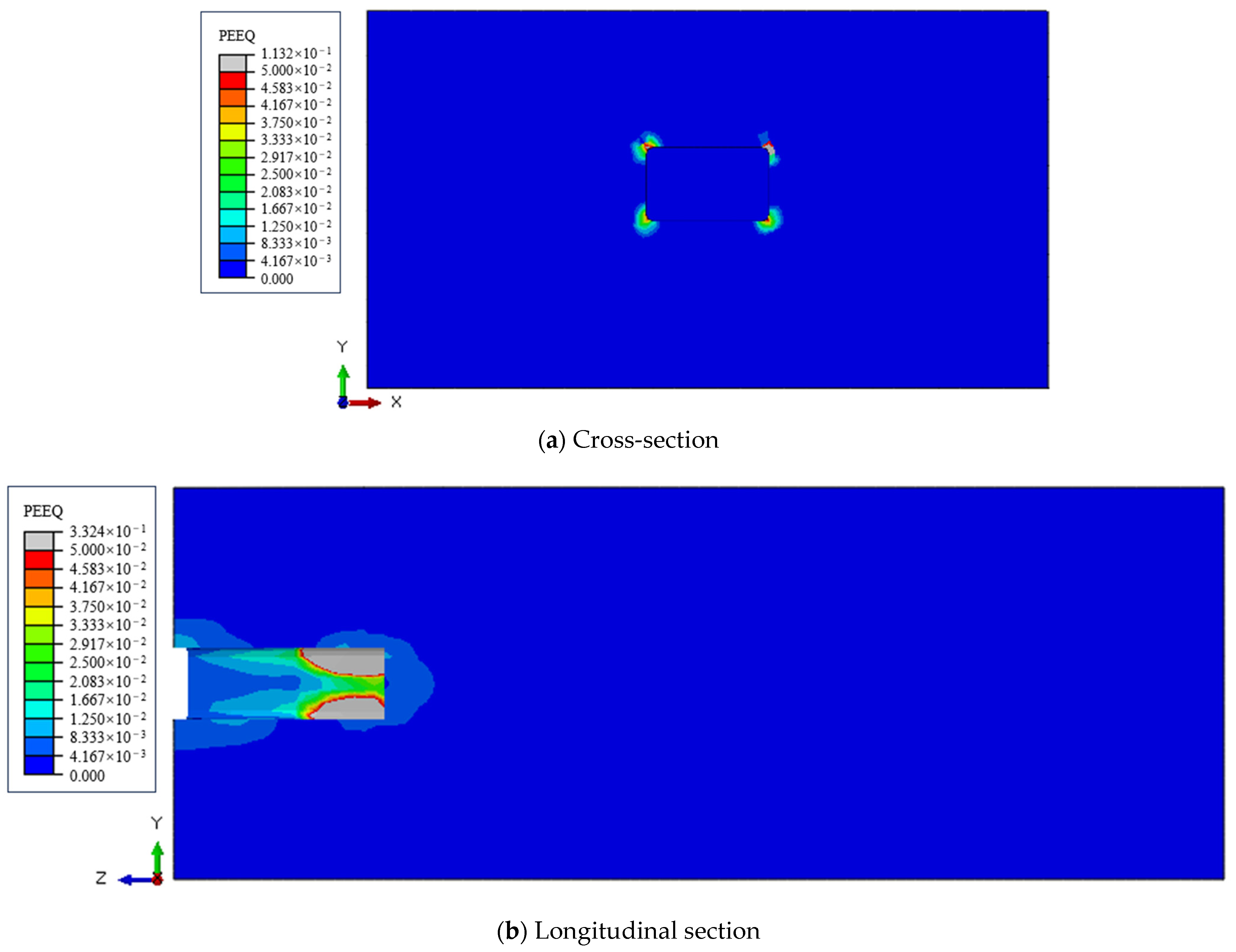
In the early stage of jacking, the equivalent plastic strain begins to occur at the round chamfer of the rectangular pipe jacking, and the equivalent plastic strain of the soil near the hole and the microtunnel boring machine is obvious.
(2)
In the early development stage of the carrying-soil effect, due to the uncoordinated internal deformation of the soil, the range of the equivalent plastic strain area is continuously expanding, gradually extending to the surface and forming a plastic deformation shear zone between the soil and the soil with no obvious plastic deformation. This uncoordinated internal deformation of the soil is also one of the reasons for the local uplift of the surface.
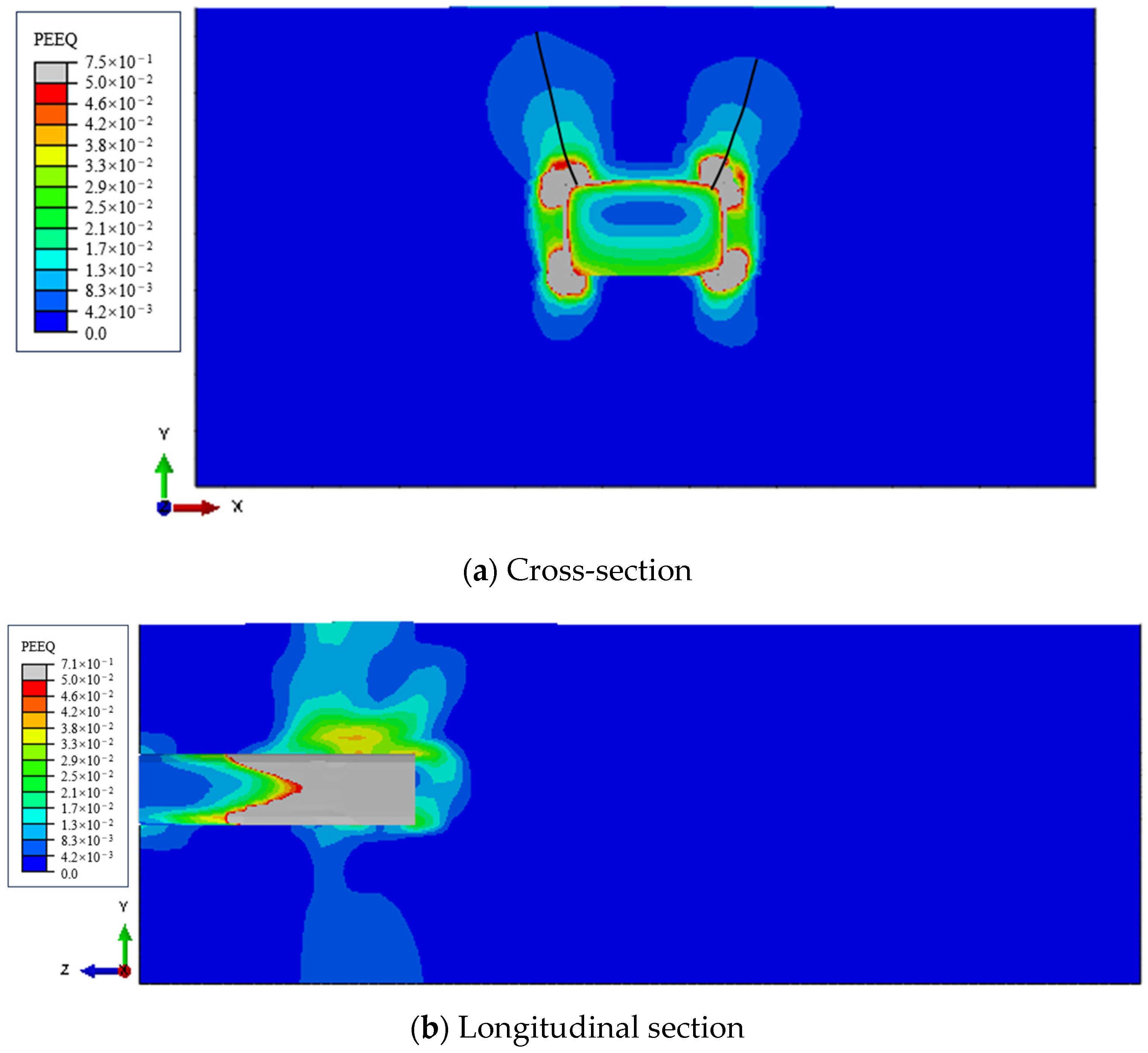
(3)
In the later development stage of the carrying-soil effect, the plastic deformation shear zone extending to the surface gradually increases. When the distribution of the equivalent plastic zone of the soil in the cross-section of the forward jacking carrying-soil area no longer changes, the soil will move forward as a whole, and the overall carrying-soil effect phenomenon appears.
(4)
After the carrying-soil effect occurs in the stable stage, the plastic strain distribution of the stratum that the microtunnel boring machine has passed through tends to be stable, and the stable state extends forward with the jacking process, which also reflects the process of the continuous extension of the whole carrying-soil area.

Author Contributions

Writing—original draft, P.Y., B.L., P.Z., C.Z., Y.X. and R.W.; Writing—review & editing, T.X. All authors have read and agreed to the published version of the manuscript.

Funding

This research received no external funding.

Data Availability Statement

Data are contained within the article.

Conflicts of Interest

The authors declare no conflict of interest.

References

  1. Baosong, M. Trenchless Engineering; People’s Transportation Publishing House: Beijing, China, 2008. [Google Scholar]
  2. Sun, Y.; Wu, F.; Sun, W. Two underground pedestrian passages using pipe jacking: Case study. J. Geotech. Geoenviron. Eng. 2019, 145, 05018004. [Google Scholar] [CrossRef]
  3. Wen, K.; Shimada, H.; Zeng, W.; Sasaoka, T.; Qian, D. Frictional analysis of pipe-slurry-soil interaction and jacking force prediction of rectangular pipe jacking. Eur. J. Environ. Civ. Eng. 2018, 24, 814–832. [Google Scholar] [CrossRef]
  4. Ma, P.; Shimada, H.; Sasaoka, T.; Hamanaka, A.; Moses, D.N.; Dintwe, T.K.; Huang, S. A new method for predicting the friction resistance in rectangular pipe-jacking. Tunn. Undergr. Space Technol. 2022, 123, 104338. [Google Scholar] [CrossRef]
  5. Wang, L.; Chen, X.; Su, D.; Zhou, W.; Sun, B.; Pan, J.; Feng, M. Construction of a super-large prefabricated rectangular tunnel beneath a box culvert using pipe jacking: A case study. Tunn. Undergr. Space Technol. 2024, 152, 105913. [Google Scholar] [CrossRef]
  6. Deng, C.M.; Peng, J.M.; Shen, G.H. Discussion on control methods of ground surface settlement caused by rectangular pipe jacking construction in soft soils. Chin. J. Undergr. Space Eng. 2016, 12, 1002–1007. [Google Scholar]
  7. Limin, P.; Zhe, W.; Yichao, Y.E. Technological development and research status of rectangular pipe jacking method. Tunn. Constr. 2015, 35, 1–8. [Google Scholar]
  8. Binquan, Y.; Chuancan, C. Pipe Jacking Construction Technology; People’s Transportation Publishing House: Beijing, China, 2003. [Google Scholar]
  9. Gao, Y.; Feng, C.-Y.; Peng, C. Overall-carrying-soil effect of shallow buried rectangular pipe jacking. Chin. J. Geotech. Eng. 2018, 40, 1936–1942. [Google Scholar]
  10. Ma, P.; Shimada, H.; Ma, B.S. Research status and development trends of key technologies of rectangular pipe jacking. Tunn. Constr. 2022, 42, 1677. [Google Scholar]
  11. Dou, X.T.; Wang, H.P.; Cao, W.M. Cause Analysis and treatment measures for overall-carrying-soil effect of shallow-buried rectangular pipe jacking. Tunn. Constr. 2019, 3, 145–151. [Google Scholar]
  12. Zhen, L.; Zhang, X.Y.; Li, X.J. On Discrimination Method and Treatment Measures for Overall Soil-carrying Effect of Shallow-buried Rectangular Pipe Jacking Projects. Mod. Tunn. Technol. 2022, 59, 167–171. [Google Scholar]
  13. Gao, H.; Wu, J.; Yang, W.S. Study on Restraining Effect of Separation Wall on Carrying-soil Effect of Pipe Jacking. Mod. Tunn. Technol. 2022, 59, 1120–1126. [Google Scholar]
  14. Fei, K.; Peng, J. Explanation of Geotechnical Engineering Examples in ABAQUS; People’s Post and Telecommunications Publishing House: Beijing, China, 2017. [Google Scholar]
  15. Li, T.L. Elastoplastic Mechanics; China University of Geosciences Press: Wuhan, China, 2006. [Google Scholar]
  16. Zhao, C.G.; Bai, B.; Wang, Y.X. Principles of Soil Mechanis; Tsinghua University Press: Beijing, China, 2017. [Google Scholar]
  17. Zhang, J.; Li, X.; Wang, X. Method for judging seismic stability state of soil slopes. Chin. J. Geotech. Eng. 2018, 40, 2096–2102. [Google Scholar]
  18. Liu, M.; Zhiyin, W.; Han, B. Equivalent Plastic Strain Entropy Method of Slope Stability Assessment and its Application. Sci. Technol. Eng. 2013, 13, 9109–9113. [Google Scholar]
  19. Hu, Y.Q.; Tang, L.S.; Li, Z.Y. Mechanism of sliding friction at pile-soilinterface of jacked pile. J. Rock Soil Mech. 2015, 36, 1288–1294. [Google Scholar]
  20. Wang, Y.H.; Zhang, M.Y.; Li, C.H. Skin Friction of Jacked Pipe Pile and Mechanism Study on Sliding Friction of Pile-soil Interface. J. Basic Sci. Eng. 2021, 29, 1535–1549. [Google Scholar]
Figure 1. Section of rectangular pipe jacking crossing stratum.
Buildings 14 03057 g001
Figure 2. Distribution diagram of monitoring points around the pipe.
Buildings 14 03057 g002
Figure 3. Schematic diagram of mud sleeve shape.
Buildings 14 03057 g003
Figure 4. Simulation of stratigraphic stratification.
Buildings 14 03057 g004
Figure 5. Pipe and microtunnel boring machine parts.
Buildings 14 03057 g005
Figure 6. The setting of the overall boundary conditions of the model.
Buildings 14 03057 g006
Figure 7. Model grid division.
Buildings 14 03057 g007
Figure 8. Distribution of pipe–soil contact friction coefficient.
Buildings 14 03057 g008
Figure 9. Relative position relationship of each component in jacking process.
Buildings 14 03057 g009
Figure 10. The setting of boundary conditions in the internal space of soil excavation.
Buildings 14 03057 g010
Figure 11. Comparison diagram of normal load around the pipe.
Buildings 14 03057 g011
Figure 12. ‘Elastic–plastic simply supported beam’ schematic diagram.
Buildings 14 03057 g012
Figure 13. Discrimination method of development direction of boundary fracture surface in carrying-soil area.
Buildings 14 03057 g013
Figure 14. The initial shape of the carrying-soil area of the cross and longitudinal sections.
Buildings 14 03057 g014
Figure 15. The shape of the carrying-soil area of the cross and longitudinal sections at the initial stage of jacking.
Buildings 14 03057 g015
Figure 16. The development stage form of the carrying-soil area of the cross- and longitudinal sections.
Buildings 14 03057 g016
Figure 17. The shape of the carrying-soil area of the cross and longitudinal sections in the stable stage.
Buildings 14 03057 g017
Table 1. Calculation parameters of strata.
Stratum NumberStratum NameStrata Thickness (m)Natural Density (kN/m3)Compression Coefficient
(MPa−1)
Compression Modulus (MPa)Cohesion Force
(kPa)
Internal Friction Angle (°)
Plain fill2.319.20.336.127.916.8
Clay3.319.90.247.441.415.7
Silty clay mixed with silt1.419.20.296.516.822.7
Silty sand mixed with silt319.10.209.44.631.4
Silty sand5.419.40.199.73.833.4
Silty clay5.619.30.306.325.717.7
Clay419.80.227.843.815.9
Table 2. Size parameters.
Dimension Parameter NameLength/mWidth/mHeight/mThickness/mChamfering Radius of Outer Circle/mChamfering Radius of Inner Circle/m
Size parameters of pipe2.59.15.50.651.250.75
Size parameters of microtunnel boring machine39.145.54-1.270.77
Table 3. Jacking construction simulation process analysis steps.
Analysis Step NameThe Step Analysis ProcessThe Jacking Mileage after the Analysis Step Is Completed/m
In situ stress balance analysis stepApply the initial ground stress and balance the initial ground stress0
Assembly analysis stepExcavation of assembly space position, microtunnel boring machine and initial assembly of some subsequent pipe0
Soil excavation 1Excavation of the soil in front of the first segment (2.5 m, the same as below)0
Overall jacking 1The microtunnel boring machine and the subsequent pipe are jacked forward as a whole (2.5 m, the same below)2.5
Soil excavation 2Complete the excavation of the soil in front of the second section2.5
………………
Soil excavation 24Complete the excavation of the soil in front of the final section57.5
Overall jacking 24Complete the last section of the microtunnel boring machine and the subsequent pipe jacking forward as a whole60
Disclaimer/Publisher’s Note: The statements, opinions and data contained in all publications are solely those of the individual author(s) and contributor(s) and not of MDPI and/or the editor(s). MDPI and/or the editor(s) disclaim responsibility for any injury to people or property resulting from any ideas, methods, instructions or products referred to in the content.

