Abstract
This technical study on strengthening a five-story building in Bucharest, a city known for its high seismic activity in Europe, required implementing a base-isolation system as part of the rehabilitation solution. The main challenge was assembling the elastomeric equipment system at the base of the building and the structural system, which was considered a rigid solid with six degrees of dynamic freedom. This required defining and solving differential equations of motion for earthquake action. It was determined that switching from a six-DoF system to a three-DoF system and then customizing the results for one DoF was justified. The analysis involved designing an isolation system with elastomeric anti-seismic devices and using a dynamic model with degrees of freedom to calculate the response for the first mode (fundamental) of seismic action from the spectral composition of an earthquake. The variation in amplitudes in the three zones—pre-resonance, at resonance and after resonance—is of great interest from a practical and design perspective. Also, the support solution was optimized in terms of the isolators’ location and the stiffness and damping parameters so that the degree of dynamic isolation could be achieved at the highest possible values (I ≥ 60%).
1. Introduction
In the context of extensive areas affected by severe earthquakes, including the case of Romania affected by the Vrancea seismogenic source, steps have been taken over time to limit the effects of seismic disasters and improve the behavior of buildings through the development of technical solutions, intelligent materials and high-performance equipment, isolation systems at the base, etc. [1,2,3,4,5,6,7,8,9].
Some aspects are worth briefly mentioning as they represent current approaches regarding the following: anti-seismic and anti-vibrating isolators depending on the significant physical–mechanical properties of the mechanism of hysteretic dissipation for internal energy [3]; various dissipative mechanisms to protect structures from pulse-type and near-source ground motions [4]; seismic isolation and response control methods of buildings [5]; types of dissipative bracing systems, passive devices with variable friction and semi-active devices with magnetorheological fluids [8]; the influence of isolation damping on the seismic response of heavily damped base-isolated buildings [9]; the extent to which seismic isolation devices allow large displacements, which have unfavorable implications, and these devices can assure the same vertical level during the motion of the base of the building superstructure [10]; the energy dissipation level based on the linear viscous damping elements [11,12]; the isolation systems that assure a compromise between contact with the soil in order to resist gravitation and separation from the soil to withstand earthquakes [13,14,15]; the method of reducing the amplitude of the vibrations at the base due to vibrations produced by inertial forces in the case of mechanical equipment with adaptive systems feedback on adaptive algorithms [16,17]; certain categories of materials with Maxwell rheological behavior [18]; functioning in the vicinity of the resonance of the mechanic equipment and/or devices [19]; a complex mechanical system, with elastic elements, subject to periodic excitations [20]; a rigid body motion between the ground–structure interface and random spatial motion [21]; the efficiency of seismic isolation as the flexibility of a soft story [22]; examples of the use of isolation systems in the case of some buildings [23,24]; the development of complex mechanical systems with elastic elements that can function as a dynamic filter for some frequencies [25]; modeling of the behavior of some elastomeric vibration-isolating elements using the finite element method [26]; and some measures to limit the increase in the lateral displacement of anti-seismic equipment [27].
In Ref. [28] are presented the advantages and disadvantages of applying the base-isolation method, a consolidation technique used on an increasingly large scale throughout the world because it changes the principle of “dissipating energy through degradation” with “dissipating energy without degradation”. The soil/site conditions play an important role when this method is adopted, and the hypothesis that the foundation soil is not a deformable medium must be taken into account so the structure–soil–foundation–seismic isolator interaction phenomenon does not appear. In addition, characteristic of the earthquakes from the Vrancea source is the fact that in some earthquakes (in 1977 and 1986), there were no influences of the soil/site conditions, but the changes in the spectral content of the ground motion appeared as a cause of the change in the mechanism of the source [10,28], and the hypothesis based on the similarity between the spectrum of seismic accelerations and the spectrum of accelerations as an effect of the base/design isolation is, thus, no longer fulfilled (earthquakes should be characterized by a spectral shape imposed, and this cannot be controlled). Under certain conditions, during an earthquake, a building with isolation at the base can have a response in the nonlinear domain, with drifts and high spectral velocities, which can lead to another phenomenon called pounding, hence the need for rigorous justification of the choice of this technical solution. The effects of seismic isolation and the nature of the structural response are verified by shaking table tests, structural health monitoring and earthquake response analyses [28].
Another direction of development is the creation of new, more efficient seismic isolation systems because most of the isolation systems reported in the literature are patented products, and, in this way, direct improvements cannot be made to them [29]. On another scale, the aspect related to the efficiency of the insulation solution at the base for rigid bodies placed at different levels of the building (which is embedded or, in turn, isolated at the base) is also presented [30].
Regarding the performance control of a structural system with isolation at the base, the combination of passive-base-isolated and active structural control represents a useful approach, through which the maximum control force and passive damper using the control–force spectrum are determined [31], which is also necessary to consider the nonlinearity of hysteretic dampers installed in isolation layers [32].
In the specialized literature, it is common only to consider a limited number of dynamic degrees of freedom when modeling the structural system of a building and its associated seismic isolator group assembly [33,34]. This is often due to simplifying assumptions or the use of simplified dynamic models [35,36,37]. However, for buildings with an isolated base, it is possible to conduct dynamic analyses using response spectrum and nonlinearity methods [38]. Furthermore, when comparing the behavior of a reinforced concrete building with four floors to one with base isolation, the latter demonstrates superior performance in terms of interstorey drifts, absolute story accelerations, base shear forces and base flexural moments when a group of isolators is applied [39].
In the given context, a more comprehensive approach is needed to accurately model the dynamic behavior during an earthquake. This is achieved through a dynamic calculation model, which assumes rigid and instantaneous vibratory motions of translation and rotation. This model considers the resistance structure to be composed solely of reinforced concrete frames.
The building was constructed in 1980 under controlled technological and quality conditions, and the provisions of the “Normative for the anti-seismic design of social-cultural, agro-zootechnical and industrial housing constructions” from 1978 were respected. With the promulgation of this norm, the expression of a dynamic factor that was established based on the response spectra of the ground motions generated from Californian surface earthquakes was changed, taking into account, as an alternative, the spectral composition of small seismic motions generated by earthquakes characteristic of the Vrancea subcrustal source. Currently, this building is an example of technical expertise with the requirements of the current regulations in force [40], with the recommendation of implementing dynamic isolation at the base, i.e., a structural mechanism favorable to the dissipation of energy from severe seismic actions expected in the future. Evaluations of the building’s geometric and structural configuration, conducted by a team of architects and engineers, have indicated that the building’s symmetry about the median transverse and longitudinal planes allows for the adoption of a dynamic calculation model as a rigid structure with six degrees of freedom, i.e., three translations along the coordinate axes and three rotations around the coordinate axes. Due to geometric and elastic symmetry, we are analyzing both coupled and uncoupled motions in modal and forced regimes under the action of the seismic force for the first spectral component of ground acceleration during an earthquake at the fundamental excitation pulsation.
The HDRB elastomeric isolator (High Damping Rubber Bearing) was tested in the ICECONTEST laboratory in Bucharest, Romania, and the experimental results are presented. These isolators are used for damping between 10% and 20% (related to specific shear strains of 100%) and, depending on the elastomer’s density, have a shear modulus between 0.4 MPa and 1.4 MPa. The novelty of this approach is that the adopted hypothesis of the building being in the form of a rigid structure with elastic links can be used with practical and relevant engineering results and high confidence in the obtained values. Thus, a model with six degrees of freedom was designed with elastic links provided by the base-isolation system. Based on the conditions of geometric, mass and elastic symmetry, six rigid eigenmodes were decomposed into two eigenmodes, each coupled with translations on the axes Ox and Oy, with normal rotations on these axes, i.e., respectively, Ox and Oy in the form (x, φy) and (y, φx). The other modes are decoupled, i.e., the vertical translation (z) and the gyration rotation (φZ) around the z-axis. The advantage of the adopted method lies in the fact that it was possible to establish analytical relationships for numerical evaluation as well as the representation of representative curves for amplitudes, forces transmitted to the building and dynamic isolation.
The data characteristics of earthquakes in Romania are summarized in the design norm P100-1/2013 [40], which also includes the seismic zoning map by regions and localities.
2. Dynamic Model
Figure 1 shows the schematization of the building, with dimensions of 50 m × 20 m × 20 m and a basement at −4.40 m, resting elastically on 20 elastomeric HDRB isolators placed symmetrically, as shown in Figure 2. The building was constructed with reinforced concrete frames, beams and columns, providing high rigidity to vertical and horizontal forces, both static and dynamic.
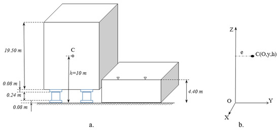
Figure 1.
Elastic support scheme. (a) Rigid body model of the building with isolation at the base. (b) Fixed system of orthogonal coordinate axes Oxyz with the position of the center of gravity C.
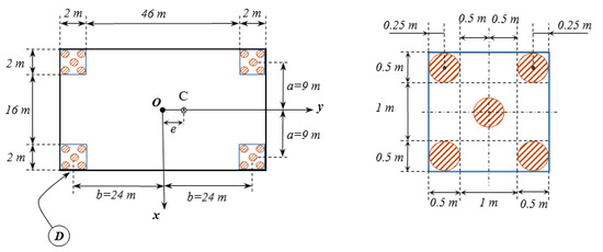
Figure 2.
Horizontal placement of elastomeric isolators (detail D represented separately on the right).
The ISN-500 seismic isolator, type HDRB, is cylindrical with intermediate reinforcements and has the following characteristics: diameter mm, total height mm, total height of the elastomer layermm, horizontal stiffnessN/m, vertical stiffness N/m and damping ratio .
For the building, the characteristic technical data are the following: total mass above the isolation system kg, the moments of inertia of a mass about the axes Ox, Oy and Oz are, respectivelykgm2, kgm2 and kgm2, and the position of the center of gravity C, with the tri orthogonal reference system Oxyz, is given by the coordinates,. The positioning distances in the plane of the groups of elastomeric isolators and the considered lengths measured between the elastic center of the support group and the reference axes Ox and Oy are relative to the axis Oy and relative to the axis Ox. The total horizontal stiffness is , and the total vertical stiffness is . The gyration radii are ,,and eccentricity . The calculation for acceleration is .
The required conditions for adopting the base-isolation solution are verified, as shown below (according to Eurocode 8, Background and applications, Base isolation, [41]):
- (a)
- The period of vibrations in the horizontal direction must be included in the range s, where is the period of the building in the assumption of its embedding in a fixed (rigid) base. For our data, , or . It follows that the request is satisfied, i.e., ;
- (b)
- The ratio of effective or equivalent vertical stiffnesses and horizontal must be . For our model, we calculate ;
- (c)
- The fundamental period in the vertical direction must be less than 0.10 s, i.e., . In the case of the analyzed model, we calculate , or substituting numerically, we obtain .
The vertical stiffness of the isolation system must be high compared to the horizontal one to reduce the number of degrees of freedom.
2.1. Differential Equations of Motion
For the dynamic model in Figure 1, we adopted the inertial excitation as the forces on the axis Ox, on the axis Oy and on the axis Oz, which results from the inertial transport motion generated by an earthquake. Projections of the acceleration vector for the first excitation mode were denoted by, and. The point of application of the inertial forces is the same as the center of gravity C. In this case, the differential equations of motion in the forced regime after the first mode of seismic excitation, with the kinematic quantity , can be written like this:
Coupled motions for instantaneous lateral motion and instant rotation (roll) results based on relationship (1) and the motions coupled for instantaneous longitudinal displacement and instant rotation (pitch) are described by Equation (2). The independent motion of instantaneous vertical translation z is given by relationship (3), and the independent motion of instantaneous rotation around the axis, Oz (gyration) is given by relationship (4).
The natural pulsations of the dynamic system without elastic couplings are of the form:
The natural pulsations of the elastically coupled vibrations are:
where α and β are given by the relationships
2.2. Amplitudes of Forced Vibrations
The analytical calculation relations were established for each vibration mode as follows:
3. Experimental Evaluation of the Parameters of the HDRB Elastomeric Device
For the HDRB elastomeric device used as an ISN-500 seismic isolator, with the diameter, the total thickness of the elastomer layers, the shear modulus , the (horizontal) shear stiffness and the axial (vertical) stiffness, the result of the tests, according to the EN15129 standard [42], carried out under a regulated regime by the laboratory certified by the EU, ICECONTEST from Romania, is presented. Figure 3 shows the excitation and response curves in the time domain for the stationary harmonic kinematic excitation regime of the form , where , and the frequency [1].
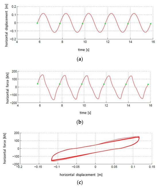
Figure 3.
Excitation and response curves during bench testing: (a) excitation with harmonic displacement; (b) force response; (c) hysteretic loop [1].
The force–displacement hysteretic loop, F-d, for the fourth loading cycle, is presented in Figure 4 [1], having been characterized by the following experimental parameters:
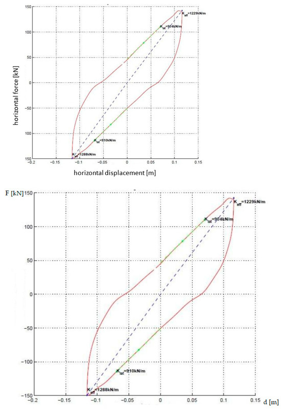
Figure 4.
Force–displacement diagram F – d for the 4th loading cycle [1].
- -
- Extreme forces and ;
- -
- Zero displacement force Q = 49 kN for zero horizontal displacement, i.e., d ≡ 0;
- -
- Maximum extreme displacements and (dbd = the calculation displacement of the isolator corresponding to the calculation displacement of the dynamic isolation system);
- -
- The energy dissipated per cycle is equal to the area of the hysteretic loop .
In this case, the secant stiffness results are
and numerically, we obtain .
The effective damping ratio for the kinematic demand regime with the given harmonic displacement law, i.e., and frequency , is determined as follows:
where is the elastic energy at maximum deformation . In this case, relationship (17) can be also written in the form:
and numerically, we obtain
Tangential stiffness k results from the hysteretic loop (Figure 4); thus:
4. Analysis of the Dynamic Response for the First Fundamental Component of Seismic Excitation
The ensemble of the dynamic response for the first fundamental component of the seismic excitation expressed by pulsation and the acceleration amplitude can be obtained based on relationships (10)–(15). Thus, considering the case where pulsation is the current variable so that , the acceleration amplitude is maintained constant, and the effectiveness of the base-isolation system depends on the degree to which it isolates vibrations from the base to the building in each direction of motion. Thus, we obtain:
4.1. The Response in Amplitudes
Amplitude variation curves , , , , and are represented in Figure 5, Figure 6, Figure 7, Figure 8, Figure 9 and Figure 10.
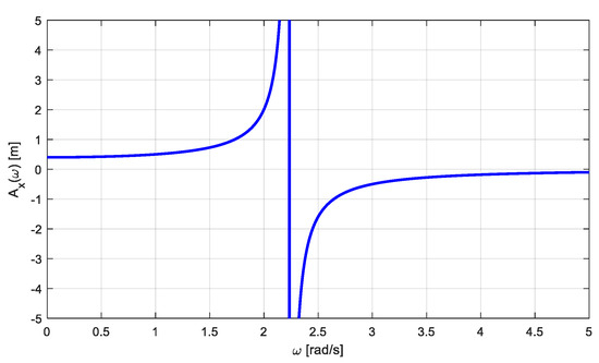
Figure 5.
Linear amplitude variation depending on pulsation in the Ox direction (coupled vibratory motion).
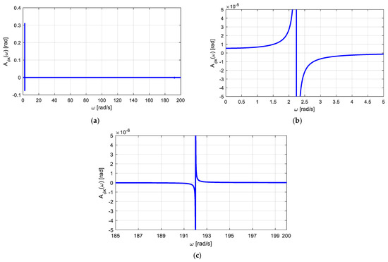
Figure 6.
The variation in the angular amplitude depending on pulsation for the angular coordinate (coupled vibratory motion). (a) Representation of ; (b) representation of , the first mode; (c) representation of , the second mode.
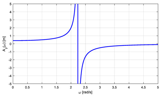
Figure 7.
Linear amplitude variation depending on pulsation in the Oy direction (coupled vibratory motion).
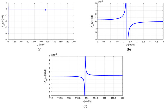
Figure 8.
The variation in the angular amplitude depending on pulsation for the angular coordinate (coupled vibratory motion). (a) Representation of ; (b) representation of , the first mode; (c) representation of , the second mode.
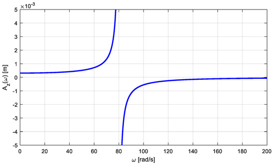
Figure 9.
Linear amplitude variation depending on pulsation in the Oz direction (decoupled vibratory motion).
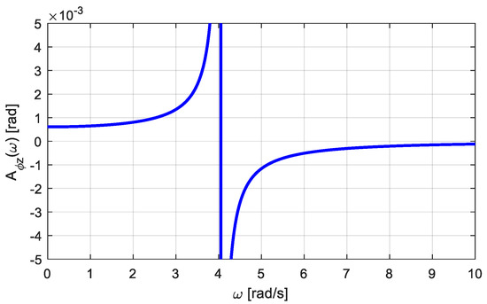
Figure 10.
The variation in the angular amplitude depending on pulsation for the angular coordinate (decoupled vibratory motion).
From the analysis of the amplitude variation curves, the dominant dynamic behavior results are as follows:
- (a)
- Amplitude , according to the direction Ox, for the domain of analysis , Figure 5, is characterized by three distinct areas, namely:
- ○
- at a constant level, for, in pre-resonance;
- ○
- for , at resonance;
- ○
- for , in post-resonance.
- (b)
- Amplitude , according to the direction of the angular coordinate , for the domain of analysis , Figure 6, highlights two distinct modes of vibration for and ; in the case of studying the given model, we are only interested in the specific domain for , i.e., the dominant motion of the angular vibrations for the three different areas, namely:
- ○
- for in pre-resonance;
- ○
- at resonance;
- ○
- for in post-resonance.
It is found that the amplitude values of the order 10−5 rad can be neglected, which means that the rotation is zero;
- (c)
- Amplitude , according to the direction Oy, for the domain of analysis , Figure 7, has three distinct areas, namely:
- ○
- constant for in pre-resonance;
- ○
- for at resonance;
- ○
- for in post-resonance.
- (d)
- Amplitude , according to the direction of the angular coordinate, for the domain of analysis, Figure 8, highlights two distinct modes of vibration for and ; it has been found that for our model’s application with seismic excitation, the primary/dominant mode is intended for, according to Figure 8; amplitude valuesare of the order 10−4 rad, which means this rotating oscillatory motion around the longitudinal axis can be neglected;
- (e)
- (f)
- The uncoupled rotation amplitude around the axis Oz (gyration motion), Figure 10, has values of the order 10−3 rad, which can be neglected, so rotational motion (gyration) about the vertical axis Oz does not occur.
In conclusion, the only dominant motions are represented by the instantaneous translational vibrations after the rectangular axes Ox, Oy and Oz, so the rigid model can be treated as a system with three decoupled degrees of freedom, with significant instantaneous harmonic translations after the first excitation mode.
4.2. The Degree of Dynamic Isolation
Based on Equations (19)–(23), we created graphs to illustrate the dynamic isolation degree for each degree of freedom, as shown in Figure 11, Figure 12, Figure 13, Figure 14 and Figure 15. These figures present the results obtained for the case under study.
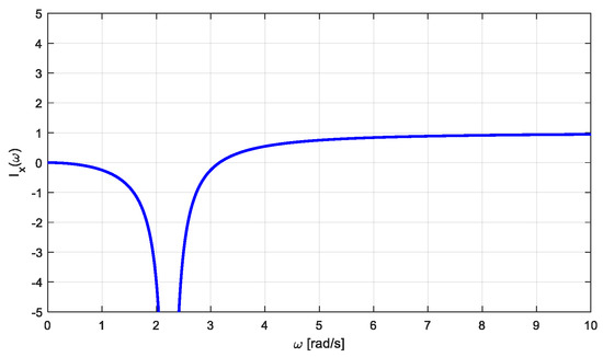
Figure 11.
The degree of isolation depends on pulsation .
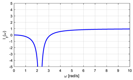
Figure 12.
The degree of isolation depends on pulsation .
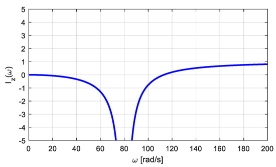
Figure 13.
The degree of isolation depends on pulsation .
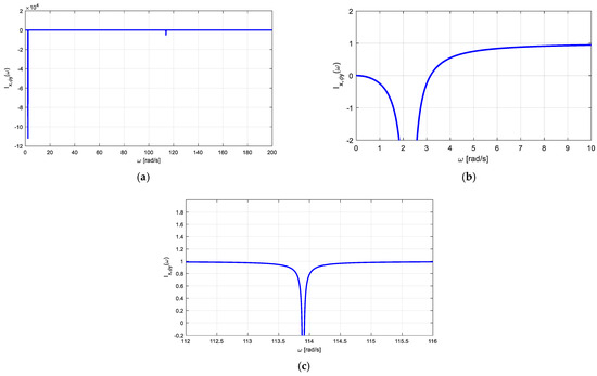
Figure 14.
The degree of isolation depends on pulsation . (a) Representation of ; (b) representation of; (c) representation of .
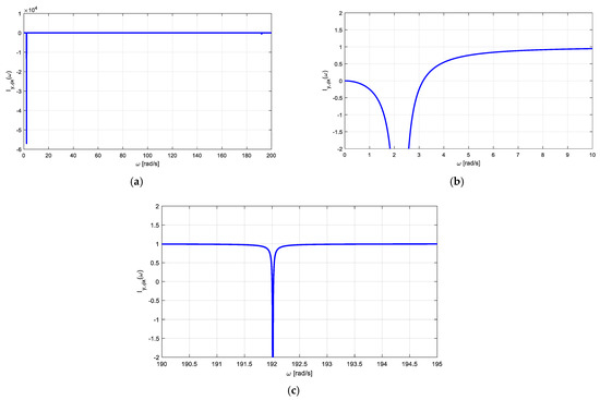
Figure 15.
The degree of isolation depends on pulsation . (a) Representation of ; (b) representation of ; (c) representation of .
From the analysis of the variation in the degree of dynamic isolation for each motion, the following results were obtained:
It follows from the above that the impact of the rotations based on the angular coordinates is so minimal that it can be disregarded.
5. The Simplified Calculation Model of the Rigid Structure with One Degree of Freedom
For motion in the horizontal plane, as the most representative of the dynamic isolation effect, we consider that in the Ox direction and the Oy direction, the instantaneous harmonic translations are independent. At the same harmonic inertial excitation in each direction, we obtained the same amplitude because and, where c is the linear viscous damping coefficient of the elastomer, and determined by trials.
The application data are , , , , and. The amplitude of the translational vibratory motion is given by the relationship
or numerical results.
The degree of dynamic isolation is given by the relationship
in which, entering the numerical data, we obtain or .
6. Conclusions
Technical solutions for isolating the base of buildings in areas with high seismic activity are crucial for protecting against earthquake damage. Typically, contractors must consider the concept, design and implementation of base isolation for buildings that can be modeled as rigid with elastic or viscoelastic connections at the base. This study focuses on the potential for dynamic modeling of base-isolated buildings using elastomeric isolators and silicone oil-based fluidic dissipators. The calculation model presented in this article simulates the dynamic behavior of a building in need of rehabilitation, taking into account its geometric, mass and symmetry characteristics, as described in the introduction. The isolation system in this model consists solely of elastomeric isolators. The scientific and original content of the article consists of the fact that the dynamic modeling of the rigid structure with elastic links at the base, as well as the particularities of symmetry about the median vertical transverse and longitudinal planes, allows an analytical approach in the linear–elastic domain. In this way, the six dynamic degrees of freedom are grouped into a system of coupled motions (x, ) and (y, ) and another group of decoupled (independent) motions (z) and (), according to the relationships (1) and (2), and (3) and (4), respectively.
For the dynamic model adopted, the analytical calculation relationships (10…15) were established, based on which the response curves were elevated for a seismic excitation represented by the first excitation mode with acceleration a = a0 and pulsation ω extracted from the spectral composition of the curve of excitation specific to the seismic zone in which the building is located. The advantage of this analytical approach lies in the fact that both the designer and the evaluator of the level of dynamic isolation can estimate with a high level of confidence the behavior of the building in response to dominant motions. In this case, depending on the mass parametric values of translation and rotation, geometric dimensions of the building, positions of the isolators and mass and geometric symmetries, variation curves were drawn for the amplitudes of motion as a function of the variation in the excitation pulsation, and the motions were highlighted significant and dominant in the possible domain of variation in the excitation pulse. The variation in amplitudes in the three zones—pre-resonance, at resonance and after resonance—is of great interest from a practical and design perspective.
The evaluation of the level of dynamic protection with the isolation system at the base was carried out based on the calculation and elevation of the curves of the degree of dynamic isolation according to relationships (19)–(23).
The design solution was based on the adoption of an elastomeric insulator HDRB type ISN-500, whose stiffness and internal damping characteristics were experimentally determined in an EU-notified and accredited laboratory, ICECONTEST from Bucharest—Romania, according to relationships (16) and (18), under the provisions of EN 15129 for anti-seismic devices [42].
About the above, the following conclusions can be summarized:
- (a)
- Linear dynamic modeling in the form of a rigid structure with elastic links at the base allows physical–mechanical highlighting and the development of a numerical analysis algorithm for the response parameters of motions after six degrees of freedom;
- (b)
- The evaluation presented for a building with particularities of geometric and mass symmetry in translations and rotations means that the dynamic calculation model, in the linear regime of the isolation system at the base, highlights two coupled motions (x, ) and (y, ) as well as two decoupled (independent) motions, (z) vertically and () rotating around the z-axis;
- (c)
- The shear stiffness parameters as well as the damping rate of the elastomeric seismic isolator were determined experimentally according to the European standard EN 15129 in the ICECONTEST laboratory in Bucharest (Romania), which is accredited by the EU;
- (d)
- The analytical elevation of the motion characteristics expressed by the amplitudes after the six degrees of freedom is illustrated in Figure 5, Figure 6, Figure 7, Figure 8, Figure 9 and Figure 10, from which the dominant motions result for the excitation domain specific to the map with the area where the site of the rehabilitated building is located;
- (e)
Thus, it is found that the degree of dynamic isolation is greater than 80% for the coupled motion (x, ) and (y, ) at pulsations in the range ω ≥ 3.5 rad/s to ω ≤ 6.5 rad/s. In coupled motions, mode 1 is dominant for the specified seismic excitation, while mode 2 at high pulsations is insignificant for the excitation given by the earthquake;
- (f)
- The dominant and significant motions for the rigid structure with elastic links, as follows from Figure 5, Figure 6, Figure 7, Figure 8, Figure 9, Figure 10, Figure 11, Figure 12, Figure 13, Figure 14 and Figure 15, are essentially represented only by instantaneous harmonic translations along the three coordinate axes.
This fact is possible only in the case of the mass distribution of the entire building along the three coordinate axes with very high values of the mass moments of inertia, and ;
- (g)
- The simplified dynamic model, based on the analysis of the dominant translational motions, allows the motion parameters along the horizontal axes Ox and Oy, representative of the evaluation of the efficiency of the isolation system at the base, to be evaluated with (25) and (26);
- (h)
- In the case of seismic excitation mode 1, the amplitude of vibration for the entire system (structural and isolator) is lower after passing through resonance, indicating a de-amplification of motion; also, the degree of dynamic isolation is higher after passing through the resonance zone.
Finally, this study shows that the adaptation of the rigid model with elastic links for a building with base isolation based on the assumption of linear–elastic behavior can provide both dynamic analysis and a numerical calculation algorithm to design and realize an effective base-isolation system with over 80% degree of dynamic isolation.
As a future approach, the case of structure–soil interaction correlated with the technical measure of isolation of the base of a building should be studied, as it is known that some soil conditions play an important role in dynamic structural behavior. Also, seismic monitoring of the behavior of buildings with isolation at the base could be a source of information leading to a thorough understanding of the coupled and uncoupled motions of a building during a severe earthquake.
Author Contributions
Conceptualization, P.B.; Methodology, P.B.; Writing—original draft preparation, P.B.; Writing—review and editing, P.B., D.D., O.V. and C.-F.D. All authors have read and agreed to the published version of the manuscript.
Funding
Publication of this paper was supported by the project CNFIS-FDI-2024-F-0599, the Technical University of Civil Engineering Bucharest (UTCB), through the institutional Open Access program.
Data Availability Statement
The original contributions presented in the study are included in the article; further inquiries can be directed to the corresponding author.
Conflicts of Interest
The authors declare no conflicts of interest.
References
- Bratu, P. Dynamic Isolation: Vibration and Seismic Actions; Impuls: Bucharest, Romania, 2021; ISBN 978-973-8132-86-3. [Google Scholar]
- Meirovitch, L. Principles and Techniques of Vibrations, 1st ed.; Prentice Hall International Editions Series; Pearson Inc.: Hoboken, NJ, USA, 1996. [Google Scholar]
- Bratu, P.P.; Mitu, A.M.; Vasile, O. Dissipation capacity evaluation for neoprene anti-seismic isolators under harmonic dynamic excitations. Rom. J. Acoust. Vib. 2011, 8, 67–71. [Google Scholar]
- Makris, N.; Chang, S.P. Effect of damping mechanisms on the response of seismically isolated structures. UCB/PEER 1998. [Google Scholar] [CrossRef]
- Nakamura, Y.; Okada, K. Review on seismic isolation and response control methods of buildings in Japan. Geoenvironmental Disasters 2019, 6, 7. [Google Scholar] [CrossRef]
- Seki, M. (Building Research Institute, Japan). Personal Communication, 2017. Available online: http://ccers.utcb.ro/images/noutati/seki/seki3.pdf (accessed on 15 August 2024).
- Marioni, A. Testing requirements of anti-seismic devices and available testing facilities. In Anti-Seismic Devices; Springer: Berlin/Heidelberg, Germany, 2024; pp. 85–109. [Google Scholar] [CrossRef]
- Mitu, A.M.; Sireteanu, T.; Ghita, G. Passive and Semi-Active Bracing Systems for Seismic Protection: A Comparative Study. Rom. J. Acoust. Vib. 2015, 12, 49–56. [Google Scholar]
- Tsai, H.C.; Kelly, J.M. Seismic response of heavily damped base isolation systems. Earthq. Eng. Struct. Dyn. 1993, 22, 633–645. [Google Scholar] [CrossRef]
- Vlad, I. Seismic base isolation in Romania. In Proceedings of the 9th U.S. National and 10th Canadian Conference on Earthquake Engineering, Toronto, ON, Canada, 25–29, July 2010. [Google Scholar]
- Popa, S.A. (Romanian Academy, Institute of Solid Mechanics, Bucharest, Romania). Personal communication, 2020.
- Tonciu, O.; Bratu, P. Evaluation of the energetic parameters of viscous dissipation for dynamic systems excited in the harmonic regime. Acta Tech. Napoc. Ser. Appl. Math. Mech. Eng. 2023, 66, 367–374. [Google Scholar]
- Potirniche, A. Assessments regarding effective configurations of vibration isolators based on displacement analysis. Rom. J. Acoust. Vib. 2015, 12, 126–131. [Google Scholar]
- Sireteanu, T. Smart suspension systems. Rom. J. Acoust. Vib. 2016, 13, 2. [Google Scholar]
- Kim, Y.-S. Study on the effective stiffness of base isolation system for reducing acceleration and displacement responses. J. Korean Nucl. Soc. 1999, 31, 586–594. [Google Scholar]
- Vasile, O. Active vibration control for viscoelastic damping systems under the action of inertial forces. Rom. J. Acoust. Vib. 2017, 14, 54–58. [Google Scholar]
- Rades, M. Resonance Methods for the Dynamic Analysis of deformable structures. Appl. Mech. Stud. Res. 1993, 32, 607–633. [Google Scholar]
- Bratu, P.; Tonciu, O.; Dobrescu, C.F.; Vasile, O. The Dynamic Response of the Vibrating System in the Case of the Maxwell Rheological Model. In Proceedings of the International Conference on Acoustics and Vibration of Mechanical Structures 2023, Kuala Lumpur, Malaysia, 5–7 December 2023; Springer Proceedings in Physics. Volume 302. [Google Scholar] [CrossRef]
- Bratu, P.; Dobrescu, C.F. Evaluation of the Dissipated Energy in the Vicinity of the Resonance, depending on the Nature of Dynamic Excitation. Rom. J. Acoust. Vib. 2019, 16, 66–71. [Google Scholar]
- Vlase, S.; Marin, M.; Bratu, P.; Shrrat, O.A.O. Analysis of Vibration Suppression in Multi-Degrees of Freedom Systems. Rom. J. Acoust. Vib. 2023, 19, 149–156. [Google Scholar]
- Murzea, P. Alternative Kinematic Assumptions for the Motions of Structures with Multiple Dynamic Degrees of Freedom Subjected to Seismic Actions. Rom. J. Acoust. Vib. 2014, 11, 53–58. [Google Scholar]
- Pinarbasi Seval, K.D.; Kelly, J.M. Seismic isolation for soft-story buildings. In Proceedings of the 10th World Conference on Seismic Isolation, Energy Dissipation and Active Vibrations Control of Structures, Istanbul, Turkey, 28–31 May 2007. [Google Scholar]
- Marioni, A. Seismic Retrofitting of Three Important Buildings in Italy and Turkey. In Improving the Seismic Performance of Existing Buildings and Other Structures; American Society of Civil Engineers: Reston, VA, USA, 2012. [Google Scholar] [CrossRef]
- Ghindea, C.; Topa, N. Case study on some structures with an isolated base. In Proceedings of the International Scientific Conference CIBv, San Diego, CA, USA, 9–11 September 2008. [Google Scholar] [CrossRef]
- Scutaru, M.L.; Vlase, S.; Marin, M.; Modrea, A. A new analytical method based on the dynamic response of planar mechanical elastic systems. Bound. Value Probl. 2020, 1, 104. [Google Scholar] [CrossRef]
- Potirniche, A.; Capatana, G. Assessments Regarding Effective Configurations of Vibration Isolators Based on Strain Analysis. Ann. “Dunarea de Jos” Univ. Galati Fascicle XIV Mech. Eng. 2015, 22, 29–34. [Google Scholar]
- Zhou, X.Y.; Han, M.; Yang, L. Study on protection measures for seismic isolation rubber bearings. ISET J. Earthq. Technol. 2003, 40, 137–160. [Google Scholar]
- Carr, A.; Puthanpurayil, A. Base isolation: The good, the bad and the ugly. In Proceedings of the 2021 New Zealand Society for Earthquake Engineering Annual Technical Conference 2021, Christchurch, New Zealand, 14–16 April 2021. NZSEE Document Repository. [Google Scholar]
- Mohammed, I. Seismic isolation of structures. Part I: Concept, review and a recent development. Asoc. Cient´ıfico-T´Ecnica Hormig´Estructural (ACHE) 2018, 69, 147–161. [Google Scholar] [CrossRef]
- Contento, A.; Di Egidio, A. On the use of base isolation for the protection of rigid bodies placed on a multi-story frame under seismic excitation. Eng. Struct. 2014, 62–63, 1–10. [Google Scholar] [CrossRef]
- Sato, D.; Chen, Y.; Miyamoto, K.; She, J. A spectrum for estimating the maximum control force for passive-base-isolated buildings with LQR control. Eng. Struct. 2019, 199, 109600. [Google Scholar] [CrossRef]
- Chen, Y.; Sato, D.; Miyamoto, K.; She, J. Response-spectrum-based design method for active base-isolated buildings with viscous dampers and hysteretic dampers. Mech. Syst. Signal Process. 2022, 180, 109413. [Google Scholar] [CrossRef]
- Zhu, Q.; Han, Q.; Yang, X.; Lin, J. Dynamic Characteristics Analysis of a Rigid Body System with Spatial Multi-Point Supports. Appl. Sci. 2022, 12, 746. [Google Scholar] [CrossRef]
- Pecchillo, G. 3D Seismic Base Isolation of Large Structures using Elastomeric Bearings. Master’s Thesis, Politecnico di Milano, Milan, Italy, 2019. [Google Scholar]
- Kulkarni, J.A.; Jangid, R.S. Rigid body response of base-isolated structures. J. Struct. Control 2002, 9, 171–188. [Google Scholar] [CrossRef]
- Leblouba, M. Selection of seismic isolation system parameters for the near-optimal design of structures. Sci. Rep. 2022, 12, 14734. [Google Scholar] [CrossRef]
- Qian, X.; Sato, D.; Osabel, D.M. Equivalent SDOF Models for Estimating Isolation-Layer Energy Dissipation in Base-Isolated Tall Buildings under Strong Winds. Buildings 2024, 14, 329. [Google Scholar] [CrossRef]
- Cancellara, D.; De Angelis, F. Dynamic assessment of base isolation systems for irregular in plan structures: Response spectrum analysis vs. nonlinear analysis. Compos. Struct. 2019, 215, 98–115. [Google Scholar] [CrossRef]
- Aydin, E.; Ozturk, B.; Kilinc, O.F. Seismic Response of Low-Rise Base Isolated Structures. In Proceedings of the 15th World Conference on Earthquake Engineering, Lisbon, Portugal, 24–28 September 2012. [Google Scholar]
- Seismic Design Code, P100-1/2013; Developer Technical University of Civil Engineering Bucharest, Ministry of Development Regional and Public Administration. The Official Monitor of Romania: Bucharest, Romania, 2013.
- Bisch, P. Eurocode 8, Background and Applications, Base Isolation. IOSIS. EGIS. 2011. Available online: https://eurocodes.jrc.ec.europa.eu/sites/default/files/2022-06/S8_EC8-Lisbon_Ph%20BISCH.pdf (accessed on 15 August 2024).
- SR EN 15129; Anti-Seismic Devices. National Organization for Standardization—ASRO: Bucharest, Romania, 2018.
Disclaimer/Publisher’s Note: The statements, opinions and data contained in all publications are solely those of the individual author(s) and contributor(s) and not of MDPI and/or the editor(s). MDPI and/or the editor(s) disclaim responsibility for any injury to people or property resulting from any ideas, methods, instructions or products referred to in the content. |
© 2024 by the authors. Licensee MDPI, Basel, Switzerland. This article is an open access article distributed under the terms and conditions of the Creative Commons Attribution (CC BY) license (https://creativecommons.org/licenses/by/4.0/).