Article

A Novel Approach to Detecting Blockages in Sewers and Drains: The Reflected Wave Technique

1
School of Energy, Geoscience, Infrastructure, and Society (EGIS), Heriot-Watt University, Edinburgh EH14 4AS, UK
2
T-SQUARED, Glasgow G33 1AP, UK
*
Author to whom correspondence should be addressed.
Buildings 2024, 14(10), 3138; https://doi.org/10.3390/buildings14103138
Submission received: 17 July 2024 / Revised: 13 September 2024 / Accepted: 24 September 2024 / Published: 1 October 2024
(This article belongs to the Section Building Energy, Physics, Environment, and Systems)

Abstract

:
Blockages in sewers and drains often result in overflows and flooding that cause significant environmental pollution and public health risks, particularly in hospitals, where the consequences can be catastrophic. Due to their low “visibility”, sewers and drains are inherently difficult to monitor and maintain, resulting in a reactive management approach whereby maintenance or repair is carried out only after a system failure has occurred. This paper investigates the feasibility of applying the reflected wave technique, a unique sonar-like monitoring approach capable of identifying changes in the geometry of closed-pipe conduits, as a means of proactive system monitoring. The technique uses a 10 Hz sinusoidal air pressure wave which is transmitted into the drainpipe. When the pressure wave encounters a system boundary, a reflection is generated which alters the measured test pressure response. Analysis of the reflections generated by a changed system boundary, such as the formation of a blockage, can provide information related to the location of that boundary within the system. An experimental setup was developed to simulate a horizontal drain using standard pipework of 100 mm diameter and 70 m length. The technique was able to detect applied blockages with cross-sectional coverage of 30% and 75%, and lengths ranging from 30 mm to 3000 mm. Accuracy was improved when the pressure sensor was positioned closer to the blockage. When the sensor was 3.4 m from the blockage, location estimates were very accurate (−2% to 3% error). At a 14 m distance from the blockage, the error increased to between 4% and 33%. The accuracy of blockage detection and location improved with increasing blockage cross-sectional area and length. Overall, the reflected wave technique could provide a potentially continuous monitoring solution for blockage detection in sewers and drains.

1. Introduction

Approximately 300,000 sewer blockages occur in the UK each year, with an associated cost of £100 million [1]. These blockages often lead to sewer flooding, causing distress and disruption to homeowners and businesses and resulting in high clean-up costs and increased insurance premiums.
Analysis of data produced by OFWAT in 2006 showed that, in England and Wales, 78% of the total number of flooding incidents recorded were caused by sewer blockages, of which 13% resulted in internal property flooding [2]. More recent data from OFWAT shows that in 2020–2021, more than 6000 incidents of internal sewer flooding occurred, caused by a blockage or a collapsed sewer, and a further 28,000 external sewer flooding incidents were recorded [3].
An investigation by Water UK revealed that wipes made up around 93% of the material causing sewer blockages, with less than 1% being products designed to be flushed, like toilet paper [1]. Most wipes do not break down in water and so can accumulate in sewers and drains, ultimately causing blockages within the system. Other materials that cause blockages include fat, oil, food scraps, and sanitary items such as towels and tampons [4]. The water industry acknowledges that, in order to avoid blockages from occurring, more needs to be done to encourage people to dispose of non-flushable items into bins, rather than flushing them down toilets [5].
The diameter of the sewer and drainpipe can impact the type and frequency of blockage formation. The majority of pipes in the sewer network have a diameter of 300 mm or less [2]. The smaller-diameter pipework at the upstream end of the sewer network, connecting individual buildings to the sewer, tend to have more intermittent water flows, often having periods of no flow, and so can suffer discontinuous transport of waste solids [6]. Blockages in smaller-diameter pipes can, therefore, be more commonplace. Larger diameter sewers are prone to gradual buildup of waste solids over time, resulting in a sustained reduction in the sewer’s water flow capacity and an increased risk of blockages developing within the system over time. Drain diameters generally range between 100 and 300 mm [7,8], and sewer diameters measure up to 900 mm or more [9].
Another important factor exacerbating the formation of blockages within drains and sewers is the impact of necessary water conservation measures and the drive to reduce per-capita water usage in residential and commercial buildings due to population pressures and climate change effects [10]. Reduced flush volume and dual-flush toilets, by their very design, reduce the flow of water available to carry and remove waste solids and other materials being flushed into the sewer and drain network. Reduced discharge flow has been shown to alter the hydraulics of waste solid transportation and ultimately lead to an increased risk of blockages occurring within horizontal drains [11,12].
Anecdotal evidence suggests that blockages in hospital drains are a highly frequent and recurring issue that poses real risks to public health and imposes demands on resources and maintenance staff. In addition to public health impacts, sewer flooding also has major impacts on the environment causing degradation of water quality, air quality, and soil quality [13].

1.1. Methods of Blockage Detection

Early detection and location of blockages in sewers and drains is crucial in order to avoid sewer flooding and should be part of timely maintenance. Conventional methods for “finding” blockages use simple approaches such as: (i) visual inspections to identify slow-draining water and/or material accumulation at drain entry points [14], or (ii) remote-controlled camera inspections that provide internal images of the sewer/drainpipe [15]. However, these methods are slow, relatively expensive, and rely on the experience/expertise of the inspectors and system accessibility. They are, therefore, not suitable for rapid inspection or continual monitoring of a sewer and drain network, which is important if sewer blockages are to be dealt with proactively.
Studies have begun to explore the use of acoustic and transient wave techniques for blockage detection in piped systems, including sewers and drains [16]. Whilst most of these methods are still within the developmental stages, these approaches have gained significant interest in recent years as they can potentially provide high sensitivity, flexibility, speed, and the ability to deal with complex systems.
Bin Ali et al. [17] have developed a method that uses an acoustic-based sensor to detect blockages and identify structural characteristics within a full-scale sewer pipe in the laboratory. The signal received from the acoustic-based sensor was shown to locate a blockage and indicate the characteristics of the blockage.
Mabpa et al. [18] used Fast Fourier Transform (FFT) to determine the resonance frequency of a simulated sewer pipe. The resonance frequency of the pipe is shown to shift with the presence of a blockage. However, this approach has significant limitations, as the location of the blockage could not be determined by the resonance frequency alone, and the smoothing of the data was found to cause an error in the readings. Furthermore, the approach was shown to be mostly impractical as the receiving microphone would be required to be installed within the pipeline, which would be a challenge.
Whilst not specifically focused on sewers, Abdullahi and Oyadiji [19] used Ansys Fluent computational fluid dynamics (CFD) software to illustrate a procedure for the detection, location, and sizing of blockages within fluid-filled pipes using an acoustic wave propagation method. Whilst this method is based on simulated CFD data, it demonstrated that both the blockage size and the mean fluid flow velocity alter the pressure amplitude of the transmitted and reflected wave. The method was, therefore, shown to not only locate blockages within a 4% error, but also to enable the size of the blockage to be estimated.
Nasraoui et al. [20] developed a method for detecting small blockages in water supply pipes using high frequency acoustic waves. Experimental validation of the method indicates that blockages of up to 15% of the pipe diameter can be detected and their length and size can be estimated within a 4% error.
Papadopoulou et al. [21] applied acoustic reflectometry for the detection of leaks and blockages within gas pipelines. The approach is shown to be capable of indicating the size and type of defect and is largely unaffected by the material of the pipeline. Whilst their results are not wholly conclusive, they suggest that the technique can be successfully applied to defect detection in both single pipelines and pipe networks with large diameters and of lengths of 5 km or more.
A more recent study by Monteiro et al. [22] also used acoustic reflectometry to detect and locate blockages in offshore gas pipelines. This study combined experimental tests, numerical simulations, and a full-scale onshore water-filled pipeline to demonstrate the feasibility of the approach. By injecting a short-duration acoustic pulse into the pipeline, the location and relative size of the blockage was determined by analysing the arrival time between measured signal reflections. Estimations of the blockage location were within 2% and the test was able to identify sizes of blockages down to 10% of the pipe area.
In this paper, acoustic reflectometry, referred to here as the reflected wave technique, is applied to the detection and location of blockages within sewers and drains. The authors have previously developed the technique as a means of detecting and locating depleted water trap seals in building drainage systems to minimise cross-transmission of disease [23,24,25].

1.2. The Reflected Wave Technique

The reflected wave technique has been widely used for anomaly detection across a range of applications, such as finding faults in electrical systems and power networks [26,27]; leak detection in pipes [28]; and pipe blockage detection in the oil and gas industry [21,22].
The reflected wave technique works by transmitting a pressure wave into the system and analysing the reflections caused by system boundaries. As the pressure wave propagates through the system, it is altered by each boundary encountered (such as junctions, trap seals, air admittance valves, etc.), which induce a characteristic reflection onto the propagating wave [23]. Any anomalies in the system will create reflections that alter the propagating pressure wave from the “defect free system baseline”.
The type of anomaly determines the form of the reflection induced [29]. For example, an open-ended pipe induces a − 1 reflection (which appears as a pressure drop) and a closed-end pipe induces a + 1 reflection (which appears as a pressure rise); see Figure 1.
By measuring the time it takes for a reflection to return, the presence and location of the anomaly can be determined using the “pipe period” concept. The pipe period is the time taken for a pressure wave to travel to a reflecting boundary and return to source. If L is the pipe length and c is the wave propagation speed, the pipe period, T, can be determined by using the following formula:
T = 2 L c
By recording the pipe period of an induced reflection, the location of the source of the reflection can be determined. The pipe period of an induced reflection can be found by comparing a recorded pressure trace with that of the defect-free system baseline. If an anomaly exists within the system, such as a blockage, it can be detected and located using the reflected wave technique.
The reflected wave technique has several benefits over other methods as it is non-invasive, has the ability to locate faults from a single access point, and can be applied to various pipe configurations, geometries, and materials. This is important when considering building drainage system monitoring, as these systems tend to be complex with a large number of different boundaries and, in particular, water trap seals which need to be safeguarded.

2. Materials and Methods
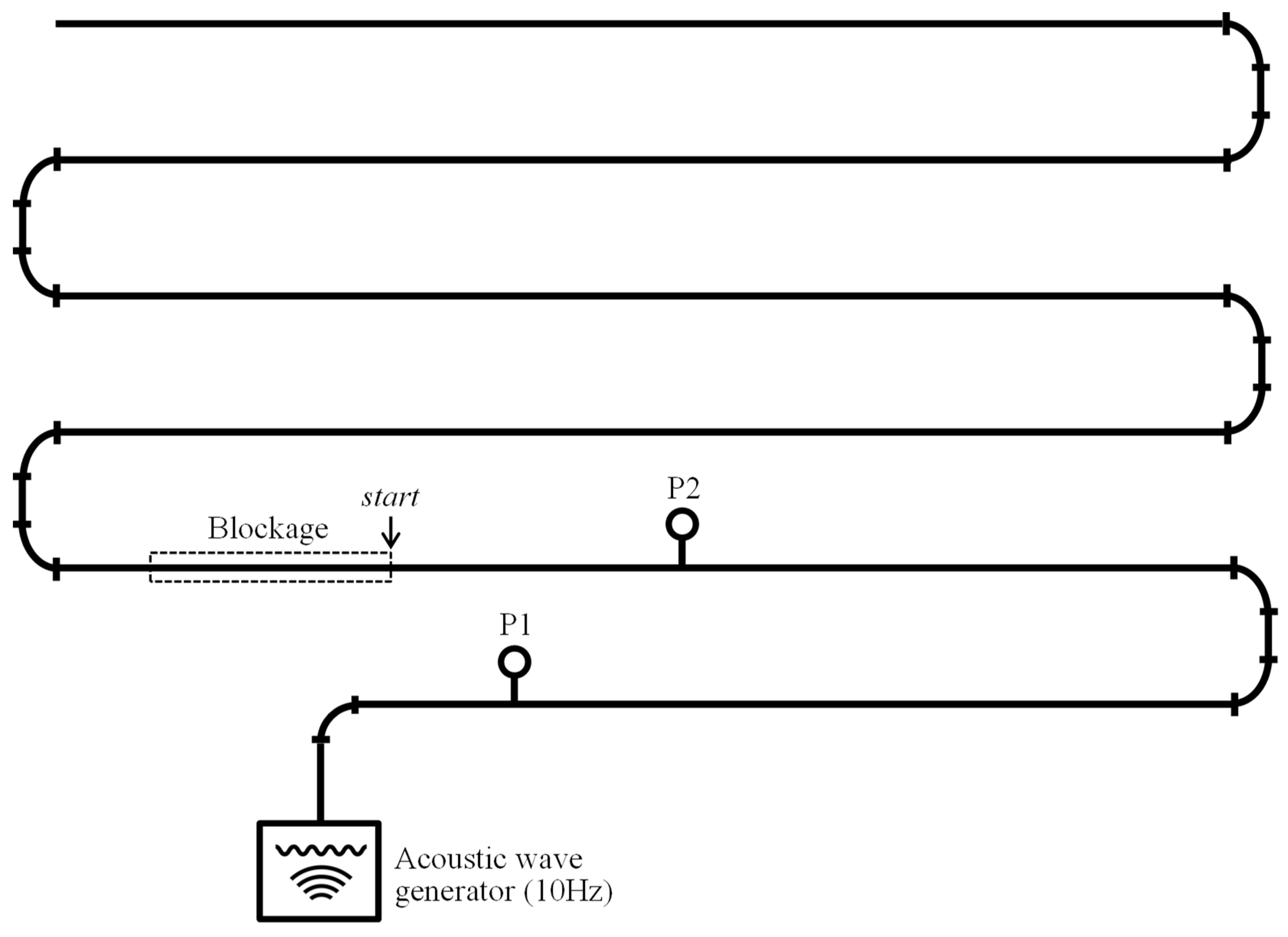
2.1. Apparatus

An experimental setup was developed at Heriot-Watt University to investigate the application of the reflected wave technique for blockage detection in sewers and drains. A test rig was constructed in the laboratory to represent a 70 m horizontal drain using 100 mm diameter uPVC pipework; see Figure 2. A diameter of 100 mm was used, this being the typical size of drain that connects residential buildings to the public sewer in the UK [30] and, therefore, appropriate for consideration of blockage formation within drains close to the building. In these initial investigations, the test rig was “dry” and contained no water, so that only the effect of the blockage in the pipe could be evaluated.
An acoustic wave generator was used to apply a sinusoidal air pressure wave into the drainpipe. A sinusoidal air pressure wave of 10 Hz was used as the applied pressure wave as this form of wave has been shown to be non-destructive when applied to building drainage systems; protecting the integrity of the water trap seals by limiting the impact of any propagating wave on the surface of the water seal and ensuring no displacement [31,32].
Two differential pressure sensors with voltage output, P1 and P2, (both SensorTechnics UK [Rugby, UK], model 113LP25D-PCB, with pressure range of ±250 mm water gauge, non-linearity and hysteresis of 0.25%, and long-term stability of ±0.2%) were connected to the test rig to record the system pressure response. P1 was located 2 m from the acoustic wave generator and 14 m from the blockage start position. P2 was located 3.4 m from the blockage start position. A consistent blockage start position was used in the tests so that the accuracy in detecting and locating blockages of different cross-sectional areas and lengths could be compared. The specific blockage start position used on the test-rig was chosen as it provided ease of access for the manual change-over of each blockage between tests, plus it allowed the effect of pressure sensor location to be examined. The pressure sensors were connected to a data acquisition board (Keithley Instruments, Inc. [Cleveland, OH, USA], model KPCI-3116) with a sampling rate of 2000 Hz.

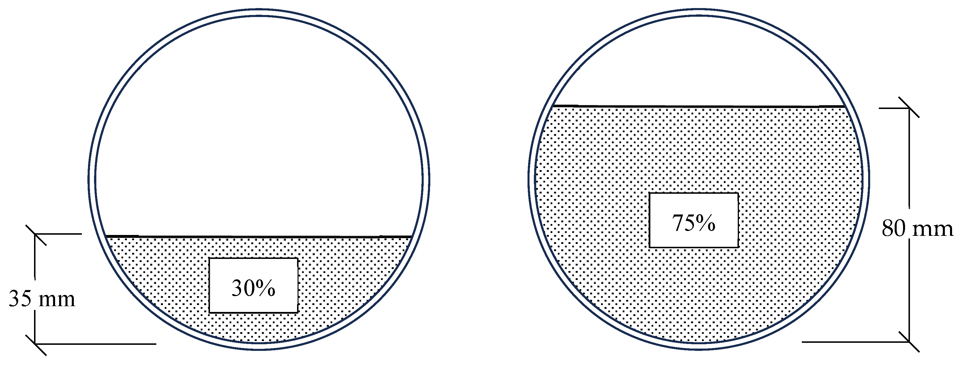
2.2. Simulating a Blockage
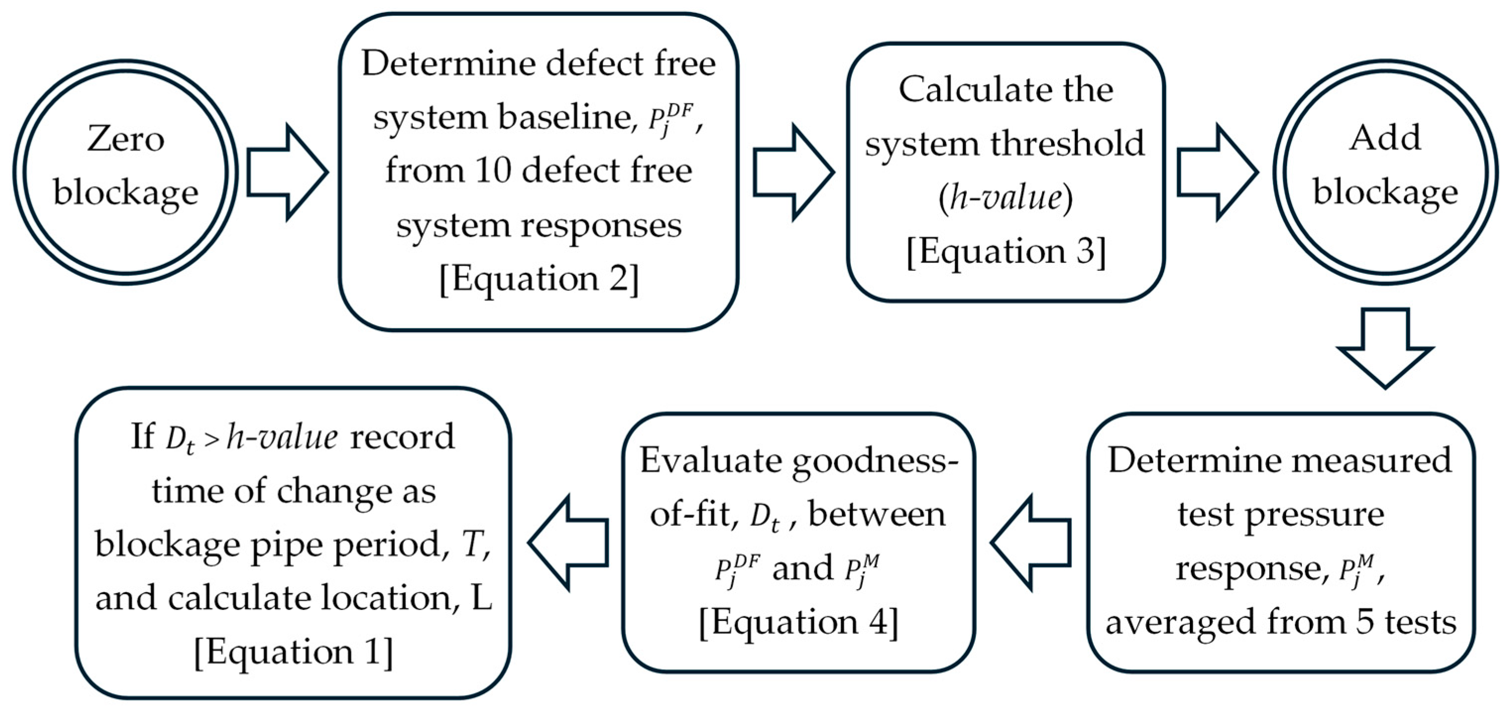
Blockages were made from concrete and cast in moulds to depict blockages filling cross-sectional areas of 30% and 75% of the drainpipe, simulating partial pipe blockages; see Figure 3. Blockages were also formed in a range of lengths (30 mm, 60 mm, 100 mm, 1000 mm, 2000 mm, and 3000 mm). Concrete was chosen as the blockage material to emulate the density of the types of blockages seen in sewers and drains, and also for practicality and ease of conducting laboratory tests.
A full list of the range of blockages used in this study is shown in Table 1. A total of 12 blockages were tested with volumes ranging from 0.07 m3 to 17.67 m3. The cross-sectional coverage values (30% and 75%) are in relation to the 100 mm diameter test-rig pipework with cross-sectional area of 78.54 cm2.
All blockages were positioned within the test rig to ensure a consistent blockage start position. This was an important factor for assessing the accuracy of the reflected wave technique in detecting and locating these blockages.

2.3. Test Procedure

The first step when using the reflected wave technique is to determine the pressure response of the system to the applied pressure wave in which no anomalies exist [16]. This is referred to as the defect-free system baseline,  P j D F , and is what all tests are subsequently compared with. The formula for this baseline is as follows:
P j D F = 1 N i = 1 N P j , i = P j , 1 + P j , 2 + + P j , N N
where N is the number of defect-free system responses and j is the measurement point. For this study, a total of 10 defect-free system responses were recorded, in response to the applied sinusoidal air pressure wave generated by the acoustic wave generator. These were then averaged to determine the defect-free system baseline.
The maximum absolute difference between the defect-free system baseline and each of the defect-free system responses was then calculated. This provides the system threshold (h-value) which takes account of signal noise when checking the goodness-of-fit between the tests and the defect-free system baseline:
h = max P j D F P j , i i = 1 i = N
The goodness-of-fit is assessed using a time series change detection algorithm based on the absolute difference, Dt, between the defect free system baseline,  P j D F , and the measured test pressure response,  P j M :
D t = P j D F P j M
For each data point, the change in goodness-of-fit is assessed. If the absolute difference between the two traces exceeds the h-value, then a change is said to have occurred (indicating the presence of an anomaly in the system), and the time of the change is recorded. This time is taken as the pipe period, T, allowing the pipe length, L, (i.e., the anomaly location) to be calculated from Equation (1). The wave propagation speed, c, is taken as 343 m/s for air in a pipe.

2.4. Adding a Blockage

Once the defect-free system baseline was determined, the blockages were added to the test rig (one at a time). Each blockage was added at the same position within the pipe to ensure consistent start positions. Once in place, the sinusoidal air pressure wave was applied, and the test pressure response was recorded. A total of 5 test pressure responses were measured for each blockage, and an average was taken, before comparing with the defect free system baseline. The overall test procedure is summarised in Figure 4.

3. Results and Discussion

3.1. Determination of the System Threshold (h-Value)

The maximum absolute difference between the 10 defect-free system responses recorded, and the averaged defect-free system baseline, was found to be 1.5 mm water gauge which was, therefore, set as the h-value for the system.
For subsequent tests with blockages, the time series change detection algorithm assessed the goodness-of-fit between the defect-free system baseline and the measured test pressure response. When a change exceeded the h-value of 1.5 mm water gauge, the time of the change was recorded and used to estimate the location of the blockage.

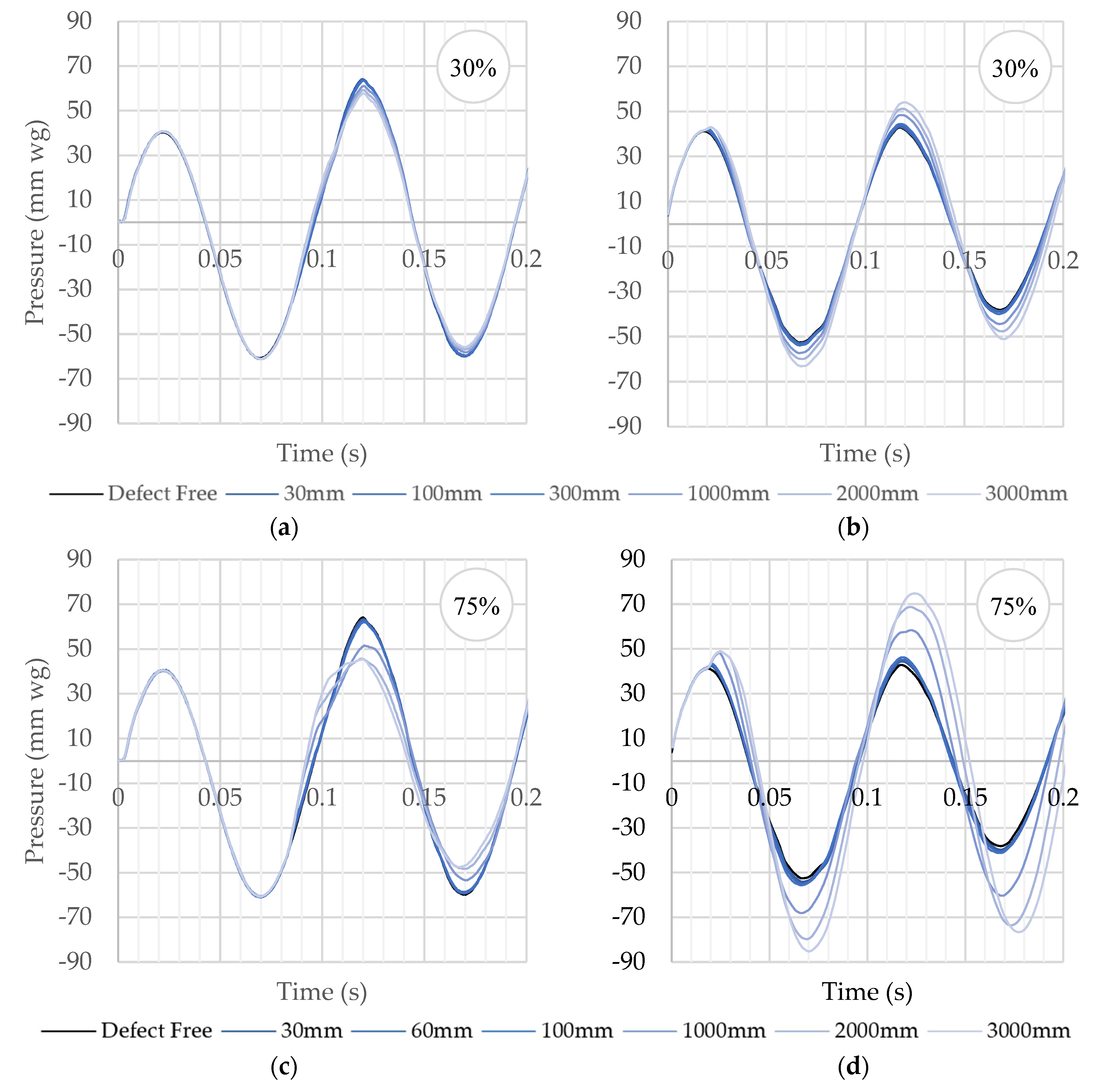
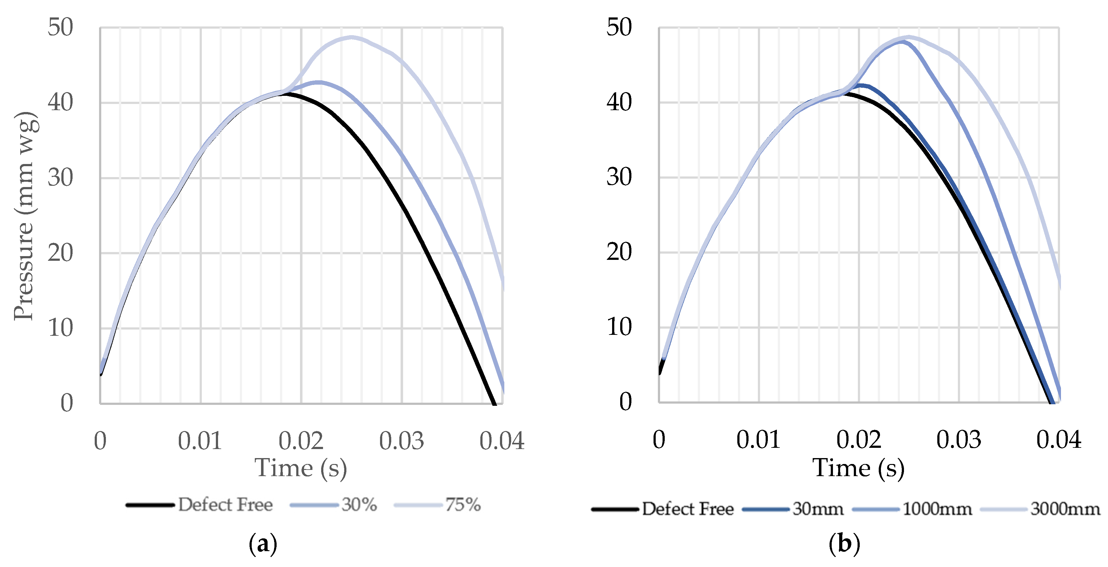
3.2. Measured Test Pressure Responses: Blockage Reflections

Each blockage was added to the test rig in turn, positioned at the consistent start position (14 m from pressure sensor P1, and 3.4 m from pressure sensor P2). Figure 5 shows the measured test pressure response for each blockage against the defect free system baselines. The presence of a blockage can be seen to alter the pressure response.
It can be seen from Figure 5 that the measured test pressure response changes from the defect-free system baseline when a blockage is present in the pipework. The change is depicted as a positive reflection that increases the pressure at a specific time, determined by the location of the blockage. This phenomenon is reported in other studies looking at blockage detection in pipelines. Papadopoulou et al. [21] compare recorded acoustic test signatures with a reference signal to locate blockages in gas pipelines and show that the test signature is altered by the presence of the blockage at a time which is dependent on the location of the blockage.
It can also be seen that the reflection change is larger and clearer when recorded by pressure sensor P2 (closest to the blockage) when compared to that recorded at P1 (furthest from the blockage). This indicates that, by having multiple pressure sensors distributed along the drainpipe, the accuracy of the blockage detection test could be enhanced, particularly in more complex networks, a finding echoed by Papadopoulou et al. [21].
Figure 5 also indicates that the magnitude of the reflection change is a factor of both the blockage cross-sectional coverage (i.e., the 75% blockage produces a larger reflection than the 30% blockage) and the blockage length (i.e., longer blockages produce larger reflections than shorter blockages). This is further illustrated in Figure 6, which compares the change in pressure response caused by both blockage cross-sectional area and blockage length over the first 0.04 s of data. It can be seen in Figure 6a that, for the same length blockage of 3000 mm, the magnitude of the reflection generated by the blockage increases with blockage cross-sectional area. Furthermore, in Figure 6b, for the same blockage cross-sectional area of 75%, the magnitude of the reflection can be seen to increase with blockage length. These findings correlate with those by Bin Ali et al. [17], Abdullahi and Oyadiji [19], Papadopoulou et al. [21], Monteiro et al. [22], and Sharp [33], who found that changes in recorded acoustic waveforms were dependent upon the cross-sectional area and/or the length of the blockage; this ultimately permits the size of the blockage to be estimated.

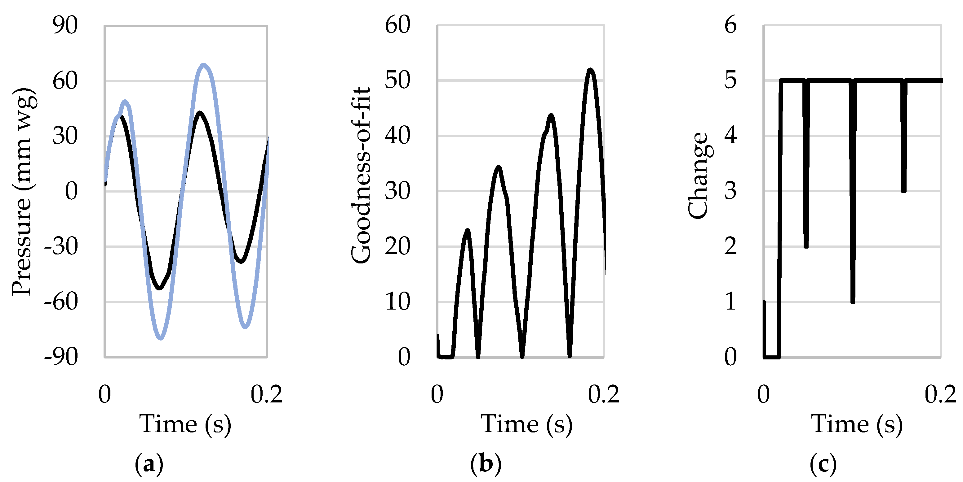
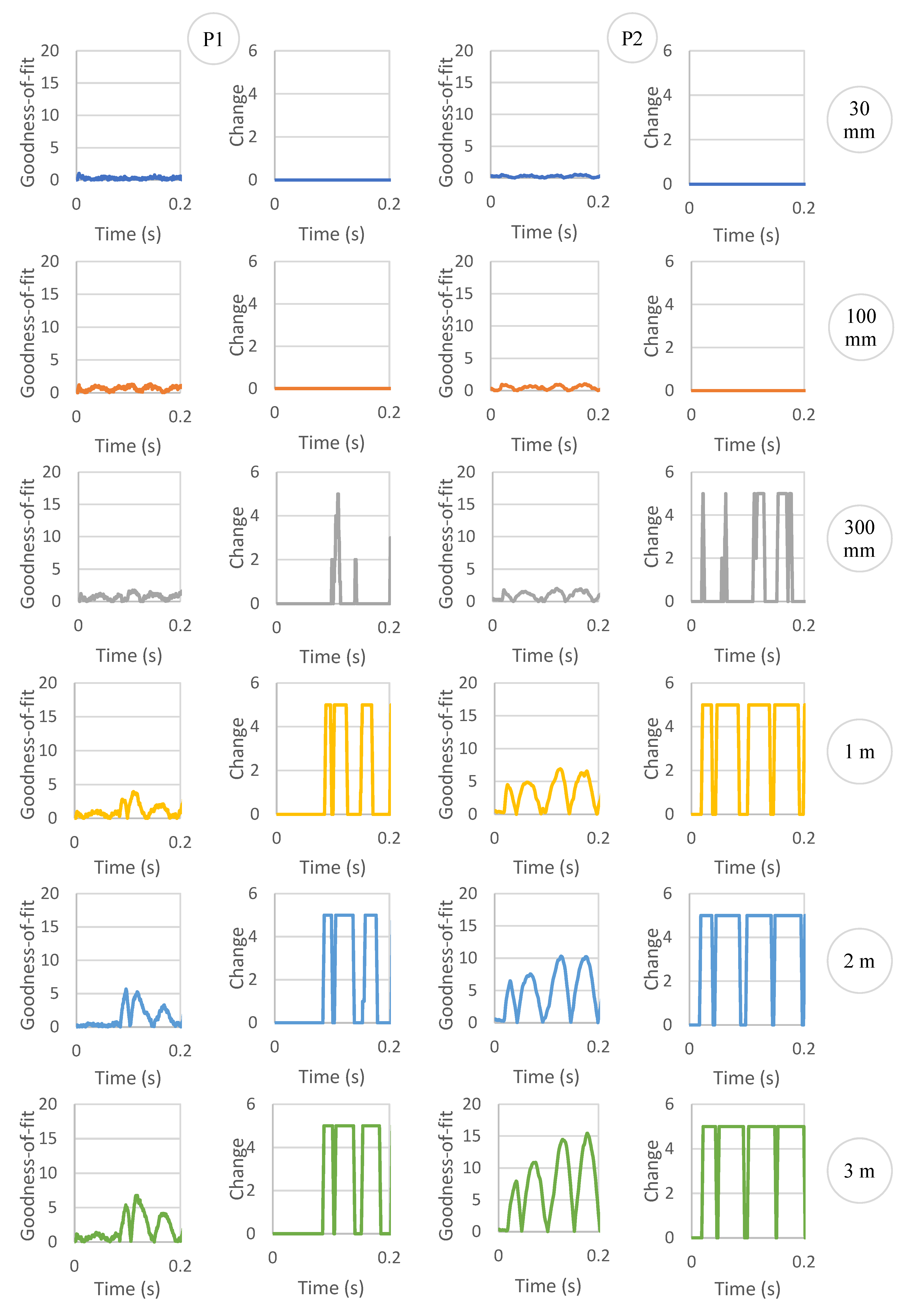
3.3. Applying the Time Series Change Detection Algorithm

Each of the measured test pressure responses was analysed by applying the time series change detection algorithm. Figure 7 shows the three steps of data analysis based on that for the 75% blockage of 2000 mm length. First, the measured test pressure response is compared with the defect-free system baseline (see Figure 7a) where the two traces can be seen to diverge at a certain time due to the reflection generated by the blockage. To identify that time automatically, the absolute difference between the measured test pressure response and the defect-free system baseline (goodness-of-fit) is calculated using Equation (4), the result of which is shown in Figure 7b. Finally, Figure 7c shows the time series change detection (indicating if goodness-of-fit exceeds the h-value 1.5 mm water gauge). The time series change detection is calculated over five consecutive data points. Once the change value reaches the value of 5, this shows that the goodness-of-fit has exceeded the h-value over 5 consecutive data points and indicates that the measured test pressure response no longer aligns with the defect-free system baseline. The first instance of the change value reaching 5 in Figure 7c is recorded as the time of the change and is used to estimate the location of the blockage using Equation (1).
The time series change detection analysis was carried out for all blockages tested. Figure 8 shows the results for the range of 30% blockage lengths, presenting both the goodness-of-fit and time series change detection graphs. The first two columns of graphs in Figure 8 (left side) depict analysis of the data measured at pressure sensor P1 (14 m from the blockage) and the second two columns of graphs (right-side) depict analysis of the data measured at pressure sensor P2 (3.4 m from the blockage). Each row of graphs relates to each length of blockage (from 30 mm to 3000 mm).
It can be seen from Figure 8 that the two shortest 30% blockages (30 mm and 100 mm) could not be detected. However, all other blockages (300 mm to 3000 mm) were detected. The clarity of the goodness-of-fit and time series change detection analysis increases with blockage length, and proximity of the blockage to the pressure sensor.
Table 2 displays the detection and location results for each blockage tested, for both the 30% and 75% blockages. The blockage characteristics (including the known location, pipe period, and length) are compared with that of the detected blockage information (including detected pipe period and detected location). Again, it can be seen that for the 30% blockage, the 30 mm and 100 mm blockages are not detected by either pressure sensor. However, for the 75% blockage, only the 30 mm blockage is not detected at pressure sensor P1; all other blockages are detected, and all blockages are detected at pressure sensor P2 for the 75% blockage.
The data in Table 2 indicate that very short blockages are either undetectable by the time series change detection algorithm or, if detected, can have a high variance in detected location (i.e., the detected location of the 30% blockage of 300 mm length, and 75% blockage of 60 mm length have a variance of 33% and 31%, respectively, compared to the known blockage location). All other blockages were located within 1–8% of the known location. The accuracy in locating the blockage is improved using data from pressure sensor P2 (closest to the blockage), with just 1–3% variance. Pressure sensor P2 was also able to locate the 75% blockage of 30 mm length to within 1% of the known location, whereas pressure sensor P1 was unable to detect it at all.

4. Conclusions

This paper presents a novel approach to detecting blockages in sewers and drains: using the reflected wave technique. Experimental tests were conducted by applying a sinusoidal air pressure wave into the system and analysing the reflections generated by a blockage using a time change detection algorithm. The main findings of the study are:
  • Detection and location accuracy: The reflected wave technique demonstrated good accuracy in detecting and locating blockages within sewers and drains. The technique was able to detect blockages with cross-sectional coverage of 30% and 75%, and lengths ranging from 30 mm to 3000 mm.
  • Sensor positioning: The accuracy of blockage detection and location improved by having multiple pressure sensors distributed along the drainpipe, with those positioned closer to the blockage showing better accuracy in estimating blockage location (−2% to 3% error) compared to those further from the blockage (4% to 33% error).
  • Blockage characteristics: The accuracy of detection and location improved with increased blockage cross-sectional area and length. Whilst small blockages were detected, the technique becomes more reliable as blockages grow in size.
  • Non-invasive and rapid monitoring: The reflected wave technique offers a non-invasive and rapid approach to blockage detection and overall system monitoring of sewers and drains. This is a significant advantage over traditional inspection methods that require direct access or camera systems.
  • Potential for proactive maintenance: By enabling early detection of blockages through continuous system monitoring, this technique could allow for proactive maintenance of sewer and drain systems, potentially reducing the risk of flooding and associated environmental health hazards.
Versatility: The technique could potentially be applied to various pipe configurations, geometries, and materials, making it adaptable to different sewer and drain systems.
The findings of this study are based on data recorded from a relatively simple test rig void of typical features found in real-world sewer and drain systems, such as pipe diameter changes, junctions, manholes, flowing wastewater, etc., all of which are likely to affect the accuracy of the test technique. Future research will focus on evaluating the transferability of the technique to larger and more complex sewer and drainpipe networks. Future work will also explore the potential for the technique to not only detect and locate blockages, but also to characterise their composition and severity. optimisation of sensor placement and signal processing will improve detection accuracy and range, with the potential that the reflected wave technique could be integrated into smart sewer management systems, allowing automated monitoring and maintenance scheduling. This approach to sewer and drain monitoring will contribute significantly to the challenges of urban water management and public health protection.

5. Patents

The work reported in this paper is protected by the following patents: EP 2061935B1 (Europe); GB 2441788A (UK); US 8336368B2 (US).

Author Contributions

Conceptualization, D.A.K., D.C. and M.G. (Michael Gormley); methodology, D.A.K., D.C. and M.G. (Michael Gormley); software, D.A.K., D.C. and M.G. (Michael Gormley); validation, D.A.K., D.C. and M.G. (Michael Gormley); formal analysis, D.A.K. and M.G. (Mark Garden); investigation, D.A.K. and M.G. (Mark Garden); resources, D.A.K.; data curation, D.A.K., M.G. (Mark Garden) and M.G. (Michael Gormley); writing—original draft preparation, D.A.K. and M.G. (Mark Garden); writing—review and editing, D.A.K., D.C., M.G. (Michael Gormley) and K.S.; visualization, D.A.K. and M.G. (Mark Garden); supervision, D.A.K., D.C. and M.G. (Michael Gormley); project administration, D.A.K., D.C. and M.G. (Michael Gormley); funding acquisition, D.A.K., D.C. and M.G. (Michael Gormley) All authors have read and agreed to the published version of the manuscript.

Funding

This research was funded by Heriot-Watt University.

Data Availability Statement

Dataset available on request from the authors.

Acknowledgments

The authors would like to thank the administrative and technical teams at Heriot-Watt University for their support during this work.

Conflicts of Interest

The authors declare no conflicts of interest.

References

  1. Drinkwater, A.; Moy, F. Wipes in Sewer Blockage Study: Final Report. Report Ref. No. 21CDP; WS; Water UK: London UK, 2017. [Google Scholar]
  2. Arthur, S.; Crow, H.; Pedezert, L. Understanding blockage formation in combined sewer networks. Proc. Inst. Civ. Eng. -Water Manag. 2008, 161, 215–221. [Google Scholar] [CrossRef]
  3. Ofwat. Customer Experiences of Sewer Flooding: A Joint REPORT by CCW and Ofwat; Ofwat: Birmingham, UK, 2022. Available online: https://www.ofwat.gov.uk/wp-content/uploads/2022/05/customer-experiences-of-sewer-flooding-a-joint-report-by-ccw-and-ofwat.pdf (accessed on 30 August 2024).
  4. Blockages. Available online: https://www.thameswater.co.uk/help/water-and-waste-help/blockages (accessed on 20 May 2024).
  5. New Proof That Flushing Wipes Is a Major Cause of Sewer Blockages. Available online: https://www.stwater.co.uk/news/news-releases/new-proof-that-flushing-wipes-is-a-major-cause-of-sewer-blockage/ (accessed on 20 May 2024).
  6. Ashley, R.M.; Bertrand-Krajewski, J.-L.; Hvitved-Jacobsen, T.; Verbanck, M. Solids in Sewers: Characteristics, Effects and Control of Sewer Solids and Associated Pollutants; IWA Publishing: London, UK, 2004. [Google Scholar]
  7. BS EN 12056-2:2000; Gravity Drainage Systems Inside Buildings—Part 2: Sanitary Pipework, Layout and Calculation. British Standards Institution: London, UK, 2000.
  8. BS EN 12056-3:2000; Gravity Drainage Systems Inside Buildings—Part 3: Roof Drainage, Layout and Calculation. British Standards Institution: London, UK, 2000.
  9. Water UK. Design and Construction Guidance for Foul and Surface Water Sewers Offered for Adoption under the Code for Adoption Agreements for Water and Sewerage Companies Operating Wholly or Mainly in England (“the Code”), Approved Version 2.1. 25 May 2021. Water UK: London, UK, 2021. Available online: https://www.water.org.uk/wp-content/uploads/2021/07/SSG-App-C-Des-Con-Guide.pdf (accessed on 29 August 2024).
  10. Mcdougall, J.A.; Swaffield, J.A. Transport of deformable solids within building drainage networks. Build. Res. Inf. 2007, 35, 220–232. [Google Scholar] [CrossRef]
  11. Gormley, M.; Campbell, D.P. Modelling water reduction effects: Method and implications for horizontal drainage. Build. Res. Inf. 2006, 34, 131–144. [Google Scholar] [CrossRef]
  12. Gormley, M.; Campbell, D.P. The transport of discrete solids in above ground near horizontal drainage pipes: A wave speed dependent model. Build. Environ. 2006, 41, 534–547. [Google Scholar] [CrossRef]
  13. Owolabi, T.A.; Mohandes, S.A.; Zayed, T. Investigating the impact of sewer overflow on the environment: A comprehensive literature review paper. J. Environ. Manag. 2022, 301, 113810. [Google Scholar] [CrossRef] [PubMed]
  14. Alshami, A.; Elsayed, M.; Ali, E.; Eltoukhy, A.E.E.; Zayed, T. Monitoring Blockage and Overflow Events in Small-Sized Sewer Network Using Contactless Flow Sensors in Hong Kong: Problems, Causes, and Proposed Solution. IEEE Access 2023, 11, 87131–87149. [Google Scholar] [CrossRef]
  15. Kumar, J.S.J.; Tiwari, J.; Khasnavis, S.; Joseph, A.A. Design of a sewer robot to detect blockages in sewer. Middle-East J. Sci. Res. 2016, 24, 236–239. [Google Scholar] [CrossRef]
  16. Yu, Y.; Safari, A.; Niu, X.; Drinkwater, B.; Horoshenkov, K.V. Acoustic and ultrasonic techniques for defect detection and condition monitoring in water and sewerage pipes: A review. Appl. Acoust. 2021, 183, 108282. [Google Scholar] [CrossRef]
  17. Bin Ali, M.T.; Horoshenkov, K.V.; Tait, S.J. Rapid detection of sewer defects and blockages using acoustic-based instrumentation. Water Sci. Technol. 2011, 64, 1700–1707. [Google Scholar] [CrossRef] [PubMed]
  18. Mabpa, P.; Na Ayudhya, P.N.; Kunthong, J. Clogged Pipe Detection and Monitoring by Using Acoustic Analysis Methodology. In Proceedings of the 17th International Conference on Electrical Engineering/Electronics, Computer, Telecommunications and Information Technology (ECTI-CON), Phuket, Thailand, 24–27 June 2020; pp. 177–180. [Google Scholar] [CrossRef]
  19. Abdullahi, M.; Oyadiji, S.O. Simulation and detection of blockage in a pipe under mean fluid flow using acoustic wave propagation technique. Struct. Control Health Monit. 2020, 27, e2449. [Google Scholar] [CrossRef]
  20. Nasraoui, S.; Louati, M.; Ghidaoui, M.S. Blockage detection in pressurized water-filled pipe using high frequency acoustic waves. Mech. Syst. Signal Process. 2023, 185, 109817. [Google Scholar] [CrossRef]
  21. Papadopoulou, K.A.; Shamout, M.N.; Lennox, B.; Mackay, D.; Taylo, A.R. An evaluation of acoustic reflectometry for leakage and blockage detection. Proc. Inst. Mech. Eng. Part C J. Mech. Eng. Sci. 2008, 222, 959–966. [Google Scholar] [CrossRef]
  22. Monteiro, P.C.C., Jr.; da Silva Monteiro, L.L.; Netto, T.A.; Vidal, J.L.A. Assessment of the Acoustic Reflectometry Technique to Detect Pipe Blockages. ASME. J. Offshore Mech. Arct. Eng. 2021, 143, 051801. [Google Scholar] [CrossRef]
  23. Kelly, D.A.; Swaffield, J.A.; Jack, L.B.; Campbell, D.P.; Gormley, M. Pressure transient identification of depleted appliance trap seals: A pressure pulse technique. Build. Serv. Eng. Res. Technol. 2008, 29, 165–181. [Google Scholar] [CrossRef]
  24. Kelly, D.A.; Swaffield, J.A.; Jack, L.B.; Campbell, D.P.; Gormley, M. Pressure transient identification of depleted appliance trap seals: A sinusoidal wave technique. Build. Serv. Eng. Res. Technol. 2008, 29, 219–232. [Google Scholar] [CrossRef]
  25. Kelly, D.A.; Gormley, M. Automatic detection of depleted fixture trap seals using the reflected wave technique. Build. Serv. Eng. Res. Technol. 2013, 35, 254–267. [Google Scholar] [CrossRef]
  26. Furse, C.; Kafal, M.; Razzaghi, R.; Shin, Y.-J. Fault Diagnosis for Electrical Systems and Power Networks: A Review. IEEE Sens. J. 2021, 21, 888–906. [Google Scholar] [CrossRef]
  27. Kingston, S.; Benoit, E.; Edun, A.S.; Elyasichamazkoti, F.; Sweeney, D.E.; Harley, J.B.; Kuhn, P.K.; Furse, C.M. A SSTDR Methodology, Implementations, and Challenges. Sensors 2021, 21, 5268. [Google Scholar] [CrossRef] [PubMed]
  28. Sharp, D.B.; Campbell, D.M. Leak detection in pipes using acoustic pulse reflectometry. Acustica 1997, 83, 560–566. [Google Scholar]
  29. Swaffield, J.A.; Boldy, A.P. Pressure Surge in Pipe and Duct Systems; Avebury Technical Press: Wiltshire, UK, 1993. [Google Scholar]
  30. A Guide to Drains and Sewers. Scottish Water. Available online: https://www.scottishwater.co.uk/-/media/ScottishWater/Document-Hub/Your-Home/Pipework-in-your-home/181223SW_Drains_Sewers_Dec23.pdf (accessed on 29 August 2024).
  31. Kelly, D.A. Identification of depleted appliance trap seals within the building drainage and ventilation system—A transient based technique. In Proceedings of the CIB W062 33rd International Symposium on Water Supply and Drainage for Buildings, Brno, Czech Republic, 19–21 September 2007. [Google Scholar]
  32. Swaffield, J.A. Influence of unsteady friction on trap seal depletion. In Proceedings of the CIB W062 33rd International Symposium on Water Supply and Drainage for Buildings, Brno, Czech Republic, 19–21 September 2007. [Google Scholar]
  33. Sharp, D.B. Increasing the length of tubular objects that can be measured using acoustic pulse reflectometry. Meas. Sci. Technol. 1998, 9, 1469–1479. [Google Scholar] [CrossRef]
Figure 1. Propagation of applied pressure wave (∆pI) along pipe and induced reflection from (a) an open-ended pipe and (b) a closed-end pipe.
Buildings 14 03138 g001
Figure 2. Experimental setup showing test rig constructed to simulate 70 m length of horizontal drainpipe with acoustic wave generator, two pressure sensors (P1 and P2) located 14 m and 3.4 m, respectively, from the blockage start position.
Buildings 14 03138 g002
Figure 3. Cross-section showing the 30% and 75% blockages within the 100 mm diameter pipework of the test-rig.
Buildings 14 03138 g003
Figure 4. Flow chart of test procedure used for applying the reflected wave technique to blockage detection in a horizontal drain test-rig.
Buildings 14 03138 g004
Figure 5. Measured test pressure responses compared with the defect free system baseline for: (a) 30% blockage recorded at P1; (b) 30% blockage recorded at P2; (c) 75% blockage recorded P1; and (d) 75% blockage recorded at P2.
Buildings 14 03138 g005
Figure 6. Details comparing change in pressure response caused by (a) blockage cross-sectional area [illustrating data for 3000 mm blockage] and (b) blockage length [illustrating data for 75% blockage], all recorded at P2.
Buildings 14 03138 g006
Figure 7. Data example of applying the time series change detection algorithm. This case is based on data for the 75% blockage of 2000 mm length and depicts (a) measured test pressure response compared (blue line) with the defect free system baseline (black line); (b) the absolute difference between the measured test pressure response and defect free system baseline (goodness-of-fit); and (c) time series change detection (indicating if goodness-of-fit exceeds the h-value).
Buildings 14 03138 g007
Figure 8. Time series change detection algorithm applied to the data for the range of lengths of the 30% blockage. The first two columns of goodness-of-fit and change (>h-value) graphs are for data recorded at P1, the second two columns are for data recorded at P2.
Buildings 14 03138 g008
Table 1. Physical properties of the range of blockages used in this study. Cross-sectional coverage values are in relation to the 100 mm diameter test-rig pipework (cross-sectional area of 78.54 cm2).
Cross-Sectional CoverageCross-Sectional Area (cm2)Length
(mm)
Volume
(m3)
30%23.6300.07
1000.24
3000.71
10002.36
20004.71
30007.07
75%58.9300.18
600.35
1000.59
10005.89
200011.78
300017.67
Table 2. Results of applying the time series change detection algorithm to detect 30% and 75% blockages of various lengths within a 100 mm diameter drain-pipe.
Cross-Sectional CoveragePressure SensorBlockage CharacteristicsDetected Blockage InformationVariance
Location (m)Pipe Period (s)Length (mm)Pipe Period (s)Location (m)
30%P1140.081630#N/A#N/A#N/A
100#N/A#N/A#N/A
3000.108518.6133%
10000.087515.017%
20000.086514.836%
30000.088015.098%
P23.40.019830#N/A#N/A#N/A
100#N/A#N/A#N/A
3000.02053.523%
10000.02003.431%
20000.02003.431%
30000.02053.523%
75%P1140.081630#N/A#N/A#N/A
600.107018.3531%
1000.085014.584%
10000.085514.665%
20000.084514.494%
30000.085014.584%
P23.40.0198300.02003.431%
600.01953.34−2%
1000.01953.34−2%
10000.02003.431%
20000.01953.34−2%
30000.01953.34−2%
Disclaimer/Publisher’s Note: The statements, opinions and data contained in all publications are solely those of the individual author(s) and contributor(s) and not of MDPI and/or the editor(s). MDPI and/or the editor(s) disclaim responsibility for any injury to people or property resulting from any ideas, methods, instructions or products referred to in the content.

