Abstract
The historical monuments of the National Preserve “Kyiv-Pechersk Lavra” play an important role in the context of preserving the UNESCO World Heritage. The scientific understanding of the buildings and structures safety management the priority of conducting repair and restoration works, the organization of their technical condition monitoring, and changes in the components of the geological environment in their locations is crucial. The purpose of this study is to identify potentially hazardous areas on the territory of the Lavra for the operation of structures by conducting a point-based integral assessment of the stability potential of the natural and technogenic system with the integration of geospatial methods and to rank the structures using the analytical hierarchy process. According to the modeling results by 17 stability factors and using ArcGIS, 37% (8.7 ha) of the Lavra territory is located in the zone of moderate hazard, 23% (5.4 ha) in the zone of potential hazard, where the manifestation and conditions of more than five dangerous engineering and geological processes intersect, and 40% (9.4 ha) in the zone of relative safety. In each zone, 10 representative structures were selected for ranking according to the stability of natural and technogenic operating conditions and their current technical condition, which is determined by nine criteria. The analysis using two methods identified the areas most at risk from seasonal fluctuations and possible military impacts and allowed us to scientifically substantiate the priority of repair and restoration work and the possibility of properly planning management measures for the selected structures, as well as to offer recommendations for improving the monitoring of the geological environment of the Lavra.
1. Introduction
There are 144 historical and architectural heritage objects of national and world significance on the territory of the Kyiv-Pechersk Lavra [1]. Their age varies from 100 to 1000 years. Throughout their existence, they have been exposed to various natural and technogenic factors. The degree of deterioration of some of them is critical, namely the Retaining Wall of the Upper Lavra—K-30a, section No. 1 of Monastery Walls—K-92, Cellar in the Metropolitan’s Garden—K-88, Powder Cellar—K-101, photos in Figure 1. Repair works were carried out in such buildings as the Assumption Cathedral—K-80, Cells of the Cathedral Monks—K-3 and K-4, Cells—K-45, Hospital with a Church—K-68, and Hospitable Court and Chamber—K-54, see Figure 1 with regard to foundation reinforcement with micropiles and foundation strengthening with concrete collars, silicification, crack injections, etc.
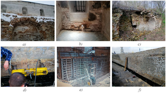
Figure 1.
The state of certain buildings of the Lavra (a–c) and strengthening (d–f): (a)—deformations of the masonry of the Monastery Walls, Section 1, K-92; (b)—rising damp, K-27; (c)—masonry destruction, Powder Cellar, K-101; (d)—tensile testing of anchors on exposed foundations, K-93; (e)—strengthening foundations by expanding them, K-44; and (f)—reinforcement with anchors, K-93, Section 3 (photographic recording I. Cherevko).
Hydrogeological monitoring has been arranged on the territory of the Lavra on the basis of 48 monitoring wells to observe changes in groundwater levels and the degree of soil moisture [2,3]. The state of crack opening in historical monuments is analyzed using geodetic marks and reference benchmarks as well as gypsum crack telltales. Periodically, non-destructive testing is carried out, with a geoelectric field and natural potential [4,5]. The improvement in the area helps to strengthen the geological environment. It also helps to prevent the negative impacts of natural factors. The improvements include surface drainage to remove melted snow and rainwater, the planting of shrubs and trees to consolidate the soil on the slopes, and a system of retaining walls and other protective systems [6]. However, the impact of abnormal weather phenomena, seasonal fluctuations in groundwater levels, and technogenic factors such as emergency leaks from networks, including heating networks, vibration loads from the operation of special equipment, the spread of vibration waves from explosions, etc., create different hazards in certain areas of the Lavra territory.
In view of the limited financial resources, there is a problem of adequate and reliable selection of the first stage structures (constructions) for repair and restoration works. It is necessary to take into account the stability of the components of the geological environment and natural and technogenic conditions for the occurrence of hazards for the historical monuments of Lavra.
There is almost no general concept of stability in engineering geology, and no general theory of stability of geological systems has been developed. This is explained by their peculiarities, which, depending on the research objectives, can be diverse in their structure and composition of elements, which complicates the comparison process between them [7,8]. The concept of stability in engineering geology is developed in relation to different geological systems and their components: certain types of soils (peats, loess, etc.), geomorphological elements (slopes, watersheds, etc.), etc. Therefore, stability assessment is carried out using different parameters.
The development of the content of the concept of “stability” goes in two directions: the study of stability as an immanent property of natural geosystems, which is inherent in the system itself and does not depend on external influences, and the study of system stability in connection with anthropogenic impact and the development of risk hazards [9,10,11,12,13]. According to the first approach, stability depends only on the structure, state, and properties of the natural, including geological, environment and does not depend on external forces [14,15]. The majority of authors adhere to the second approach. Stability assessment is also carried out using cartographic methods, where engineering and geological zoning are used to study changes in the geological environment [7]. The components of the geological environment are assessed by indicators in points, and their sums are compared within a given territory.
Most researchers [16,17] include the following natural factors that determine the stability of the geological environment: type of geological structure (age, genesis, and lithological composition of sediments); relief morphology (ruggedness and steepness of slopes); soil composition and properties (different for different types of rocks); geodynamic environment; and hydrodynamic parameters.
The multifactorial nature of the impacts makes it difficult to choose a single integrated criterion for assessing the stability of the geological environment. The existing criteria can be divided into three groups: quantitative, semi-quantitative, and qualitative. The most common is the qualitative assessment of the geological environment stability. As a relative (semi-quantitative) assessment and classification of stability, points are used and various scoring scales are introduced.
To date, there are several methods for solving decision-making problems with many criteria: methods of reducing criteria to one (principal component method, complex criterion, fair compromise, Hermeyer, and construction and analysis of the Edgeworth-Pareto set) and methods based on mathematics and psychology (multicriteria utility theory, hierarchy analysis method, methods of ranking multicriteria alternatives, etc.) [18,19,20,21,22].
To solve the problem of selecting the optimal priority of historical monuments for restoration or renovation, it is more appropriate to use the Analytic Hierarchy Process (AHP) [22]. The AHP method has been widely used in a large number of multifactorial suitability assessments and complex systemic risk assessments in the risk management of engineering projects [23,24,25,26].
To evaluate the risk of damage, in addition to identifying the causes, the vulnerability of the building and the territory (geological environment) in the vicinity of the building is assessed. Vulnerability is the property of a building to lose its operational suitability as a result of the possibility of damage under the influence of negative factors. The degree of vulnerability depends on a combination of characteristics of the building, the soil base, and the surrounding area.
The purpose of the research was to identify potentially hazardous areas on the territory of the Lavra for the operation of buildings by conducting a point-based integrated assessment of the stability potential of the natural and technogenic system with the integration of geospatial methods and to rank the buildings using an Analytical Hierarchical Process to identify the weakest and most urgent ones for restoration or renovation work. To achieve the goal, the following tasks were performed:
- Collection and analysis of materials for engineering and geological research of the territory of the Kyiv-Pechersk Lavra;
- Creation of the LAVRA-GEO database on natural and technogenic indicators in the ArcGIS geographic information system;
- Development of a parametric assessment of the stability of the geological environment;
- Drawing up maps of the stability of the geological environment and the natural-technogenic system (NTS), maps of anthropogenic loads, their analysis, and interpretation of the results;
- Justification of the choice of historical buildings and criteria that determine the conditions of their operation for analysis using the hierarchical process method;
- Interpretation of data and development of recommendations for making management decisions on preservation of Lavra’s monuments.
The methods of point integral assessment and AHP are developed in accordance with geological (structural and tectonic, lithological, engineering geological, hydrogeological, etc.) conditions. The state of the facilities (buildings, engineering systems, etc.) is taken into account as a response to changes in the geological environment.
A scientifically based prediction of the geological environment response to various anthropogenic impacts and their interaction and the creation of risk maps for the life and operation of facilities on this basis and makes it possible to correctly plan management measures for the state of local and facility-based natural and technogenic systems and to justify the spatial and temporal structure of monitoring.
2. Materials and Methods
2.1. Data Collection and Processing
The scheme of engineering protection of the territory (scale 1:1000); the plan of the current state of the Preserve (scale 1:1000); data of engineering and geological investigations [27,28,29], geodetic plan (scale 1:500); and map of the Preserve in *dwg format, historical and archaeological materials, and the satellite images of the Copernicus Sentinel-1 mission [30] are used. The documentation used includes technical passports of historical monuments and drainages, data of monitoring observations on soil removal, and water flow rate [31].
Interferometric synthetic aperture radar (InSAR) images of the Sentinel-1 mission were used for DEM generation and analysis of the morphometric characteristics of the territory—the slope angle of the surface. Data were processed in ESA SNAP 9.0.0 software using InSAR techniques [32,33]. The spatial resolution of the processed images is 14 × 14 m. To obtain slopes, the resulting image in *GeoTiff (projected to WGS84) was processed using the Raster to Point, TIN-surface creation, and Slope tools in ArcGIS [34].
The analysis of the spread of hazardous exogenous geological processes was carried out using a geoinformation approach, which involves the creation of a data bank (LAVRA-GEO) in the ArcGIS geoinformation system. The main purpose of its creation for the territory of the Preserve is to ensure the most efficient use of various information. Prior to the assessment stage, a significant amount of input information is accumulated, on the basis of which the database is formed. Conventionally, it consists of the following blocks:
- -
- Natural block contains data on the geological structure—quaternary deposits (genetic type and lithological composition, thickness, and strength properties), relief character (slope angles and degree of erosion ruggedness), groundwater depths, spread of exogenous geological processes, presence of fault zones of different levels, etc.;
- -
- Technogenic block consists of data on the configuration and area of buildings and structures, main engineering water-supply networks, and protective engineering structures (drainage systems of various types).
To integrate paper source maps into the database, raster models with an accuracy of 300 dpi were created using raster scanning technology. The average error in the position of objects and contours does not exceed ±0.3–0.4 mm at the map scale. The resulting vector models of the map data were georeferenced using the Georeferencing module, a first-order polynomial (Affine Transformation) [34]. The data were adapted to the Universal Transverse Mercator (UTM) coordinate system (datum WGS-84, zone 36 N). Depending on the quality of the images, further vectorization of the objects was performed in manual and partially automatic modes. Data on LAVRA-GEO spatial objects are stored in attribute tables in the *shp format.
The information on the location of buildings and structures (Pulkovo-1942 coordinate system) was obtained from the Preserve’s files in *.dwg format, imported into GIS in *.dxf format and georeferenced in the WGS-84 system using Open Street Map. The point objects—wells—were built using the “create feature class” tool based on a set of rectangular coordinates from the *.csv file. In this case, inaccuracies in the position of individual wells were identified (the difference in distances was 5–60 m). This is probably due to the different properties of the WGS-84 and Krasovsky ellipsoids, as well as the Gauss–Kruger projection and the Mercator universal projection when switching between different coordinate systems [35,36]. The identified errors were corrected manually under the supervision of an expert from the Preserve.
The method of quadratic assessment of the territory and methods of comparative and statistical data analysis was used for the integral scoring.
The Excel application of the Microsoft Office package was used for the AHP analysis of buildings.
2.2. Essential Characteristics of the Study Area
Administratively, the territory of the Reserve is located in the Pechersk district of Kyiv, Ukraine. It is bordered by recreational, transport, and administrative areas of the city, Lavrska Street, Dniprovskyi Uzviz (Descend), and Naberezhne Highway, and the Dnipro River flows 200 m to the east, Figure 2.
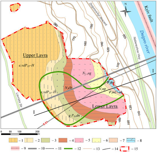
Figure 2.
Situational and geological map of the Preserve territory: 1—loess-like sandy loam; 2—loess-like loam; 3—moraine loam; 4—brown clay; 5—mottled clay; 6—Poltava sands; 7—Kyiv clay; 8—clay marl; 9—faults detected in the crystalline basement, neotectonic activity of which is confirmed by geological and geomorphological data; 10—faults detected in the crystalline basement, the neotectonic activity of which is not confirmed by geological and geomorphological data; 11—isogrades of average velocities of neotectonic movements of the Earth’s crust (cm/km/thousand years); 12—Lavra ravine rim; 13—surface contour lines, m; 14—cross-section line I-I; 15—boundaries of the Preserve.
Geostructurally, this area belongs to the Pechersk anticline high. To the east of the Reserve, the Kyiv Fault Zone is located along the Dnipro river bed. A fault has also been identified in the Proterozoic crystalline basement beneath the territory of the Reserve, but there are no reliable geological and geomorphological data to confirm its neotectonic activity. The study area includes zones with different average rates of neotectonic movements—0.005–0.01 cm/km/thousand years [37,38].
The Upper Lavra is located within the loess plateau and its slopes. The Lower Lavra is dissected by the Lavra ravine, the average depth of which is 80 m, the length along the bottom is 160 m, and the area of its territory is 85,535.12 m2. The value of ruggedness is 0.15, which refers to limited favorable conditions for economic activity.
In the geological section of the Preserve’s territory, the interlayering of rocks with different compositions and properties is horizontal or slightly sloping, which is typical for the Dnipro slopes within Kyiv, Figure 3. From the surface, under the anthropogenic layer tH, which is up to 5 m thick, there is a widespread layer of loess soils e,dvPIII-H, 10–14 m thick, which is absent only on the Dnipro slopes and in the Lavra ravine. In the loess layer, there are layers of loess-like sandy loam (3–4 m), loess-like loam (5 m), and a layer of subsurface soils e,vd PI-II (0.9–1.1 m). Below are moraine loams gPII dn (4 m) and freshwater loams lg,f PII dn (1 m). These sediments are underlain by a horizon of Pliocene-Lower Quaternary brown clays N2čb (5 m) and below by a 4 m thick layer of Miocene–Pliocene mottled clays N1sg. Beneath the clays are layers of Poltava sandstones and Neogene sands N1np (20 m) and Kharkiv Oligocene sands P3mž+ob (15 m), which are underlain by semi-confining Kyiv clays P2kν (8 m) and Paleogene marls P2kν (15–20 m). There are alluvial and deluvial soils dvPIII-H (5 m) on the slopes [27,28].
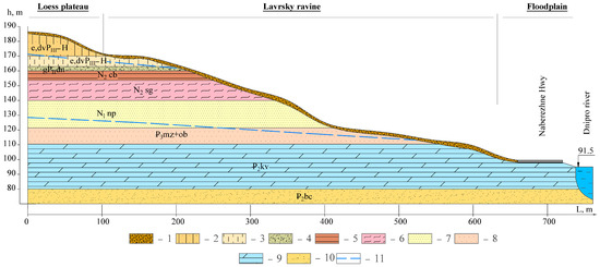
Figure 3.
The typical geological section of the territory of the Lavra along line I-I (see Figure 1): 1—technogenic deposits (tH)—light/heavy silty loam, sandy dark gray, dark brown, and brownish brown, in places humified, with inclusions of up to 10–50% construction waste; 2—eluvial eolian-deluvial deposits (e,dvPIII–H)—silty sandy loam, loess, pale gray, and gray–yellow; 3—eluvial eolian-deluvial deposits (e,dvPIII–H)—silty loam and yellowish-gray, with filiform veinlets of carbonates; 4—moraine deposits (gPIIdn)—reddish-brown loam, with thin interlayers of sandy loam and brownish-gray sand; 5—Pliocene-lower quaternary brown clays (N2cb)—light brownish-gray clay, refractory, and semi-hard, with carbonate inclusions; 6—Miocene–Pliocene molten clays (N2sg), greenish-gray and dense; 7—sandy loams and sans of Novopetrivska suite (N1np), fine-grained and light gray; 8—sands of Kharkiv suite (P3mz+ob), fine-grained and green; 9—clay marls (P2kν) and sage-green; 10—sands of Buchack suite (P2bc), greenish-gray, glauconite, and fine-grained; 11—aquifers in Quaternary deposits (first from the surface) and in Oligocene sands (second from the surface).
Loess-like loams and sandy loams (e,dvPIII—H) are widespread among the specific soils on the territory of the Preserve, covering the plateau and its slopes with a continuous cover, but they are absent on steep Dnipro slopes, landslide terraces, and in Lavra ravine. Loess-like loams are a non-subsiding fine-dusty macroporous rock with carbonate veins and nests and a columnar structure. The roof of loess-like loams on the plateau is located at absolute elevations of 174.4–175.0 m, depth 13–14 m from the ground surface. Their thickness varies from 1.1 to 5.5 m [39,40].
Loess-like sandy loams lie above loess-like loams. This is a subsiding loess highly porous rock with a high content of dusty particles (51–76%) and carbonate inclusions. It belongs to Type I in terms of subsidence, when there is no or less than 5 cm of subsidence from its own weight when soaked, and the relative deformation of subsidence Esl ≥ 0.01 [41,42]. The absolute elevations of the loess-like sandy loam roof on the plateau are 180–166 m and the thickness varies from 4 to 13 m, more often 9–12 m.
On the territory of the Lavra, there are factors that can lead to waterlogging of loess-like soils. In particular, these are accidents on water supply networks [5]. In the event of seismic events (natural and man-made) or dynamic impacts from military operations (missile or UAV strikes), negative phenomena of soil liquefaction and transition to a fluid state can occur in areas with water-saturated loess. However, given the low natural seismic activity of the Kyiv region (intensity of 4–5 points on the MSK-64 scale) and isolated cases of such accidents, this factor was not considered in the assessment of the stability of the territory in this article.
The hydrogeological conditions of the territory of the Preserve are determined by the following aquifers: in the Quaternary aeolian-deluvial and lake-glacial sediments on the plateau (Upper Lavra, upper part of the slopes, Hospitable Court, Far Caves Hill) and in the Quaternary deluvial soils on the slopes and in Oligocene (Kharkiv) sands. A characteristic feature is the formation of temporary aquifers in parts of the Lower Lavra territory. The condition of the monuments and the territory is indirectly affected by the first and partially by the second aquifers, which are actually one combined aquifer.
2.3. Development of a Parametric (Point Integral) Assessment of the Stability of a Natural and Technogenic System
Determination of the state of the Preserve’s territory as a natural and technogenic system and identification of potentially hazardous areas for the operation of facilities is based on the principles of stability and vulnerability of the geological environment to various types of anthropogenic impacts and was performed on the basis of a point integral assessment of the stability potential (GEs) using a geoinformation approach.
The stability of a natural-technogenic system is determined by the equilibrium state of the natural and technogenic subsystems. It is an integral value consisting of a set of factors—natural (FN) and technogenic (FT)—that affect the state of equilibrium.
An integral assessment of the stability of such a system is associated with certain methodological difficulties: the need to take into account a large number of factors and the impossibility of their uniform parameterization due to the fact that qualitative characteristics are used along with quantitative indicators.
Seventeen factors (F1-17) were assessed and are summarized in Table 1. Each factor is graded according to its value (criteria) into three intervals and assigned a point value (B), the higher value of which corresponds to conditions that lead to deterioration of the geological environment and operating conditions of structures with the corresponding quantitative or qualitative characteristics.

Table 1.
Parameters of assessing the stability potential of the natural and technogenic system of the Preserve territory.
For a given unit square, the assessment of the potential stability of the territory is the “sum” of the selected criteria (Formula 1). According to this, the unit square belongs to one of three types of natural and technogenic systems in terms of potential stability or occurrence of hazards (in particular, for military impacts and abnormal weather phenomena).
The validity of the choice of quantitative values of the parameters (criteria) of the factors is confirmed by the requirements of Ukrainian regulatory documents, such as State Building Regulations (DBN): DBN V.2.2-12:2018, DBN V.2.1-10-2009, DBN A.2.1-1-2008, DBN V.1.1-24:2009, and DBN V.1.1-12:2006 and the results of the work of the following pieces of research [3,7,9,11,14,15,16,17,43,44,45,46,47,48,49,50,51,52,53].
Dynamic impacts and loads were not taken into account, as the streets on the northern and western sides of the Preserve have low traffic intensity (650–800 vehicles per hour) and the territory borders on a natural landscape park in the south. The Naberezhne Highway with a high traffic intensity (9.800–10.200 vehicles per hour) is at a safe distance in terms of vibration impact. The vibration load on the territory of the Lavra from the operation of special vehicles during repair works or snow removal is episodic and does not affect the overall long-term stability potential of the natural and technogenic system of the Preserve.
According to the criteria for the evaluation parameters of the factors listed in Table 1, a map of the ranking of the Preserve’s territory was constructed, which was divided into 5 × 5 m squares. If two or more criteria of the same factor are present on the area of a single square, the assessment was made by their average weight value, as follows:
where B is the point value corresponding to certain criteria of the factor and β is the weighting index determined by the percentage of the area occupied by a certain criterion.
The ranking was carried out on an interval point scale with the gradation of the natural and technogenic system into three states according to potential stability: “relative safety” (less than 17.0 points), “moderate hazard” (17.1–21.0 points), and “potential hazard” (21.1–32.0 points). The “hazardous” condition is characterized by the presence of several negative factors or negative values of factors. Namely, these include difficult engineering and geological conditions, the development of hazardous geological processes, the presence of water supply networks, drainage collectors in unsatisfactory technical condition, etc.
2.4. Hierarchy Method
To determine the ranking of structures that are prioritized for rehabilitation or restoration, an analytical hierarchical process was used, which is based on the hierarchy analysis method [54,55]. The method uses a decision tree, in which general criteria are divided into criteria of a separate nature (alternatives).
Weighting factors are determined for each group of criteria. The alternatives are also compared with each other for each criterion. The means of determining the importance index of the criteria and alternatives is a pairwise comparison. The result of the comparison is evaluated on a point scale. Based on such comparisons, the importance index of the criteria (index local weight—ILW), the scores of the alternatives are calculated and the overall score is determined as a weighted sum of the criteria scores (index relative weight—IRW).
The hierarchy analysis method was applied in the following steps:
1. Decomposition of the problem in the form of a hierarchical structure of three levels (Figure 4): goal; criteria for comparing structures; and alternatives—a list of historical monuments located in different zones of potential stability of the NTS and in different technical conditions.
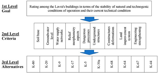
Figure 4.
Conceptual model of hierarchical analysis for the ranking of geological and engineering factors of building stability response.
At the same time, in accordance with the goal, the ranking of the criteria that determine the rating of historical monuments was selected in two groups:
- -
- Criteria for natural and technogenic operating conditions: soil base (SB), groundwater level (GWL), dangerous processes (DP), relief morphometry aspects (RMA), water supply networks (WSN), and underground structures (US);
- -
- Criteria for the technical condition of buildings: construction deformation (DC), land improvement system (LIS), and engineering strengthening (ES).
As alternatives, 10 historic buildings were selected in accordance with the requirements for the number of assessment elements [54]. Among them, 6 are in the Type III of NTS—“hazardous” and 4 buildings that, according to monitoring data, have poor technical condition characteristics, but are located in the areas of the I and II Types of NTS.
2. Prioritizing the elements of the hierarchical structure.
To prioritize the criteria and obtain estimates of alternative solutions, pairwise comparison matrices A=||aij|| are constructed. The element aij of the matrix of pairwise comparisons is the result of measuring the degree of preference of alternative Ai relative to alternative Aj on the fundamental scale. The elements belonging to the same level of the hierarchy are compared with each other. The elements of the matrices are filled in with expert assessments of the relative importance of the individual elements being compared in relation to the goal defined at the first level, according to the adopted rating scale (Table 2).
Table 2.
Assessment of degrees of element importance (criteria and alternatives) by comparison.
Second level criteria were assessed by experts according to the following guidelines/principles derived from experience:
- -
- GWL and its changes are considered to be the most influential on the development of engineering and geological processes and the bearing capacity of the structure’s foundations based on 30 years of monitoring observations. In comparison with ES, it is estimated at 9 points according to Table 2 and so on for all comparisons;
- -
- The presence of WSNs due to constantly recurring accidents and leaks from them indirectly affects the change in GWL;
- -
- Another important factor is SB. Changes in GWL, in particular its rise due to leaks, lead to changes in the physical, mechanical, and water–physical properties of soils and foundations of structures, which leads to the development of hazardous processes, subsidence, flooding, sufosis, etc.
- -
- The distribution of soil types is influenced by the relief morphometry aspects (RMA) of the territory, determining the conditions for the spread of loess-like rocks and the formation of deluvial soils on slopes.
The presence of DP on the territory reduces the overall stability of the soil massif where buildings and structures are located and requires the use of engineering protection measures.
- -
- The presence of underground structures (US) changes the natural stress–strain state of the soil massif and serves as an obstacle to the natural discharge of groundwater;
- -
- The presence of construction deformation (DC), in particular structural cracks in buildings, indirectly indicates the development of hazardous processes in soils, uneven deformations of the building, and deterioration of the building’s structural elements;
- -
- The land improvement system (LIS), which includes paving around the building, rainwater drainage, etc., contributes to the improvement in the building’s condition to a certain extent;
- -
- Preliminary repairs or engineering strengthening (ES) bring the technical condition of the building to a higher level, but the quality of the repair or the design of the strengthening solution may not lead to this level. Compared to the WGL factor, it is estimated at 1/9.
At 3rd level, the alternatives were compared with each other by each criterion according to the scoring principle presented in Table 3.
Table 3.
Characteristic of assessment acceptance of elements importance degrees at 3rd level.
The criteria are arranged in the form of matrices containing an equal number of rows and columns, where the points are recorded on one side of the diagonal, the value of 1 is placed on the diagonal of the matrix, and the points are the inverse of the diagonal. The number of expert responses to build a pairwise comparison matrix for n compared items is given by the expression n − (n − 1)/2, given that the diagonal elements of the matrix are equal to 1 and the matrix is inversely symmetric. In our case, there are 36 answers for the second level matrix and 9 matrices for the 3rd level, 9 × 45 = 405.
3. Finding a priority vector.
For each matrix, the local priorities of the elements (ILW) are calculated and compared. Each row of the matrix, and therefore the corresponding element, is matched with the geometric mean of its elements—the components of the eigenvector, Table 3. By summing up the results obtained in the column “components of the eigenvector”, we divide the geometric averages of each of the matrix rows by this sum. As a result, we obtain the local priorities of the respective elements being compared.
Using the assessments of experts (authors of the research), a matrix of pairwise comparisons for the criteria was constructed, and the index local weight (ILW) of the criteria was calculated according to the rules given in Table 2. The results of the calculations are presented in Table 4.
Table 4.
Pair-wise matrix of geological and engineering factors at the 2nd level.
4. Assessment of consistency (homogeneity of expert opinions).
For each matrix, after determining the vector of local priorities, the index of consistency of expert judgements is calculated. The check allows us to identify errors that an expert may have made when filling in the matrix of pairwise comparisons. For example, an expert indicates that alternative A1 is worse than A2 and alternative A2 is worse than A3. However, the expert also indicates that A1 is better than A3. To offer another example, the expert indicates that alternative A1 is significantly worse than A2 and alternative A2 is significantly worse than A3, but the expert also indicates that A1 is only slightly worse than A3.
The consistency ratio (CR) for matrices of dimension greater than 2 should not exceed 10% and is calculated according to the following formula:
where CI—consistency index and RI—random consistency index.
The consistency index is calculated from the values of the matrix elements using the formula
where n is the dimension of the matrix and λmax is calculated as follows: the sum of each column of the matrix of pairwise comparisons is found; the sum of the first column is multiplied by the first index of local weight (ILW), the sum of the second column by the second component, and so on; the resulting products are summed; and λmax must be greater than n.
The random consistency index is the value that would be obtained by randomly selecting judgements on the fundamental scale (1/9...9) for a given value. It is defined depending on the matrix dimension. For a 9-dimensional matrix, it is 1.45, for a 10-dimensional matrix, it is 1.49 [54]. For this matrix (see Table 3), λmax = 9.41 > 9. CR = 3.6% > 10%.
5. Hierarchical synthesis.
The priorities are synthesized starting from the second level of the hierarchy from top to bottom. The local priorities of the alternatives (3rd level structures) are multiplied by the local priorities of the relevant criteria (2nd level) and summed up for each element (structure) according to the criteria. Thus, the final assessment of an alternative in the pairwise comparison method is the index of relative weight of the alternative (IRW), which is calculated as a convolution of the weighting index of the criteria (local criteria) of all levels of the hierarchy.
The criteria of the 2nd level of the hierarchy have a general positive orientation, i.e., a higher point in the expert’s judgement corresponds to better conditions for the structures. Therefore, according to the synthesis of priorities, the alternative with a higher weight (IRW) will have better NTS conditions and a better technical state than the alternative with a lower weight in the list of selected structures.
3. Main Results
3.1. Ranking of NTS
Figure 5a shows a diagram of the stability potential of the geological environment of the Preserve by natural factors (FN). The natural stability potential is divided into four intervals for a detailed analysis of the territory conditions. The value of ∑B ≤ 16 corresponds to natural conditions that form potentially unstable areas for structures. By area, they make up 49% of the Preserve’s territory—11.51 hectares. With ∑B > 16.1, the sites are classified as unstable conditions, which are dangerous for the operation and preservation of monuments (51%—11.98 hectares).
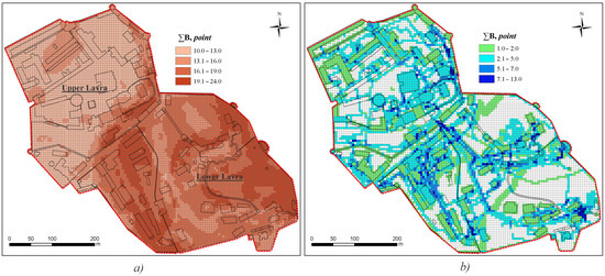
Figure 5.
Ranking the Preserve’s territory by natural—FN (a) and technogenic factors—FT (b).
Areas with a relatively evenly distributed high stability potential (Upper Lavra) and with alternating low and medium potential values (Lower Lavra) were identified.
Within the Upper Lavra, the subsoil, composed of loess-like rocks, is stable without technogenic loads. The decrease in the natural stability potential of the Lower Lavra is due to geomorphological conditions—the development of the ravine system and, accordingly, the high groundwater table and the development of hazardous geological processes—flooding, landslides, etc.
Figure 5b shows the distribution of technogenic impacts and loads (FT), which is a factor in reducing the natural stability potential of the Preserve’s territory. The area of 75% (17.62 ha) of Lavra is affected by technogenic impacts and their distribution is relatively even. Against the background of an average level (2.1–7 points) of technogenesis, the cells are intensively colored (point over 7.1) in the areas with the largest concentration of various types of technogenic impacts (2.76% of the territory with technogenic impact—0.64 ha). In this area, water supply networks are located in the surface layers, drainage systems are at depth or in close proximity, and buildings with basements or underground structures are more than 5 m deep.
Figure 6 presents a ranking map of the Preserve territory according to the stability potential of the natural and technogenic system (GEs) and highlights dangerous and potentially dangerous areas.
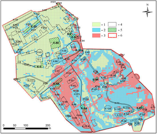
Figure 6.
Map of the stability of the geological environment taking into account natural and technogenic factors (GEs): 1—Type I (less than 17.0 points); 2—Type II (17.1–21.0 points); 3—Type III (21.1–32.0 points); 4—buildings and structures; 5—historical buildings for AHP; and 6—boundaries of the Preserve.
On the Lavra’s territory, 37% (8.7 ha) is in moderate hazard (type II), 23% (5.4 ha) is within the potential hazard (type III), where the manifestation and conditions for more than five dangerous engineering and geological processes intersect, and 40% (9.4 ha) is in relative safety (type I).
Under the influence of technogenic factors, the potential for natural stability has decreased for the territory as a whole (see Figure 5a). On the Upper Lavra, cells with an average stability potential appeared, on the Lower Lavra, the negative condition intensified. The area of sites with medium and negative stability potential increased, and the number of single cells of stable and average stability of the natural and technogenic system decreased.
By analyzing the spatial distribution of 17 characteristics, the map shows where episodes of hazardous engineering and geological processes (subsidence, landslides, and flooding) are most likely to occur as a result of abnormal weather phenomena or accidents on water supply networks, etc.
Authors consider the state of sites with safe conditions to be stable, but it may deteriorate depending on abnormal weather phenomena or accidents on water supply networks, military impacts, etc.
Authors note that many places have a transitional position between the selected types due to the close concentration of cells of different types. This affects the state of the buildings in such mixed zones and serves as a verification of the reliability of the selected zones. For example, building K-64 has deformations caused by uneven subsidence of the foundations due to waterlogging of the soil bases in the southern part with Type III of NTS. This is manifested in the occurrence of structural vertical cracks with upward openings in the load-bearing walls and in the ceilings.
In view of the fact that in some areas classified as the third type of geological environment, works have been carried out to improve the engineering condition (rehabilitation and restoration works to strengthen the foundations, improvement of engineering protection systems – radial, wall drainage, retaining walls and landscaping), the state of the buildings has been stabilized (K-45, K-63, K-57, etc.). Each type of NTS is associated with a specific mode of monuments operation. Each type of natural and technogenic system with a combination of geological and anthropogenic characteristics creates a certain potential for an emergency risk—an emergency situation that may have certain consequences (Table 5). Accordingly, areas with an “unsatisfactory” state of the geological environment have a potentially high risk of a hazardous event. The scale of potential consequences will require significant efforts to restore the previous state of geological environment components and architectural structures. For such areas, a risk factor accounting system and risk management measures should be established and developed.
Table 5.
Characterization of probability levels of hazardous event risk in different types of geological environment by stability.
The deterioration in stability potential conditions under the influence of anthropogenic loads indicates the need to use a special operating regime for monuments and, in some cases, to apply additional engineering measures for their preservation. To identify such structures and determine their priority, a hierarchy method was applied to the example of 10 representative structures.
3.2. Priority of Historical Monuments Repair Using AHP
The analysis in determining the ranking of Lavra’s buildings in terms of the stability of natural and technogenic conditions of operation and their current technical state is based on three principles: decomposition, comparative judgment, and synthesis of priorities. The comparative judgment resulted in one matrix of pairwise comparisons of criteria (see Table 4) and 10 matrices of pairwise comparisons of alternatives (each matrix contains the results of the comparison by one of the criteria).
At the second level of comparison, the rating of criteria that determine stable engineering and geological conditions and satisfactory operational state of structures according to the local priority index (0.31–0.02) was determined. As shown in Figure 7, the GWL, the presence of engineered water supply networks, and the lithology of the soil base are the most influential factors. The least significant factor is engineering strengthening, which means the presence of repair work in the building, strengthening of foundation structures, etc.
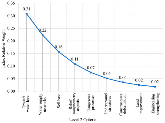
Figure 7.
The priority of the 2nd level criteria, which determine stable engineering and geological conditions and satisfactory operational condition of monuments.
The consistency check of the comparative matrix of criteria (2nd level) established that CR = 3.6%, which is less than the marginal value for error—10%. This means that the expert’s scores and judgments were consistent.
At the third level, the preference matrices were created for the buildings and compared with each other in relation to each of the 2nd level criteria. The results of the nine matrices are summarized in Table 6, with conditional color formatting. Each cell in a separate column indicates how much more stable and safe each representative structure is compared to the others. The expert’s assessments and judgments in these comparisons were consistent. The average CR value for all matrices of this level does not exceed 1.42%.
Table 6.
Impact local weight of historical buildings by each engineering and geological criterion.
Having obtained the values of local weight indexes (ILW), the value of the convolution of the relative weight index (IRW) was determined (see Section 2.4). This made it possible to assess the structures by the priority of repair and restoration works, the safety of these buildings and structures, and the organization of their technical condition monitoring, Figure 8. The lowest IRW values are for structures in unsatisfactory technical condition, which fall into areas with a hazardous type of NTS, and whose operating conditions are not maintained. There is a correlation between the type of NTS and the condition of structures determined by the AHP method.
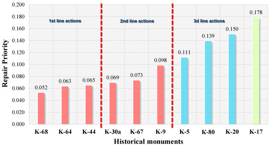
Figure 8.
Repair priority of historical monuments by using AHP. The color corresponds to the type of natural and technogenic system in terms of potential stability in which the monument is located.
The buildings were divided into three groups based on the IRW value. The buildings of Groups I and II, which are located in the potential hazard type of the NTS, were divided on the basis of a hierarchical comparative analysis into equal parts. Group I includes buildings K-68, K-64, and K-44 located in the middle part of the Lavra ravine, where the determining factor is the GWL, the formation of seasonal aquifers, and the lithological composition of the soil bases—deluvial varieties. This causes flooding of the structures’ foundations and the development of uneven subsidence of foundations, rising dampness and masonry waterlogging.
Group II includes buildings K-30a, K-67, and K-9. Geomorphologically, they are located on the edges of the Lavra ravine and Near Cave Hill (K-68). Here, the influence of the GWL is less pronounced and the soil bases are weak, although they have a more or less homogeneous lithological composition—loess loams and clays. However, a critical destabilizing factor is the presence of utility networks around them and the development of landslide processes.
The boundary between Groups II and III is drawn based on the type of NTS. Phase III includes buildings K-5, K-80, K-20, and K-17 with IRW ≥ 0.1, located in relative safety and moderate hazard areas, which ensure their stable condition without external factors (technogenic accidents or abnormal weather phenomena). These facilities are located in relatively stable natural conditions. Therefore, it is advisable to reconsider their priority, but with other structures in the same conditions by NTS type.
This ranking and division into groups allows us to apply the principle of priority of management decisions to the treatment of historical monuments, considering each group as a queue for restoration and reinforcement with engineering protection measures.
In addition, this ranking can be viewed as a gradation of the consequences of technogenic impacts. For example, in the event of military impacts (hits, downing of UAV missiles, falling debris, etc.), structures located in the third type of NTS will suffer the most. In particular, K-44, located in the middle part of the Near-Cave Hill, has an IRW of 0.065. In the event of a missile hit or debris falling within the slope, the engineering protection system may be destroyed: the drainage system in the upper part and retaining walls in the lower part. This will lead to deformations of the building up to its destruction and, in the terms of this study, to a significant reduction in IRW.
4. Discussion
The geological environment together with the sources of anthropogenic impact of any territory, including urbanized ones, can be considered as a complex geotechnical system that can be characterized if the engineering and geological conditions of the territory and anthropogenic impacts on it are known. There are positive and negative processes within such a natural and technogenic system. They either accelerate or slow down the development of engineering and geological processes and phenomena. Therefore, the issue of the gradation of anthropogenic impact parameters in determining the integral indicator of geological environment stability will be debatable. In one case, the presence of loess-like soils as soils with high bearing capacity can be regarded as a higher stability of the geological environment, but in the presence of water supply networks and water leaks, the stability of such a site will be lower.
An integral assessment of the sustainability of such a system is associated with certain methodological difficulties: the need to take into account a large number of factors and the impossibility of their uniform parameterization due to the fact that qualitative characteristics are used along with quantitative indicators. The geological environment zoning scheme is not constant in time and should be updated based on systematic monitoring observations.
In contrast to the results obtained by the AHP method, which gives an assessment based on the weighting index, the results of zoning the Preserve’s natural and technical system show the actual distribution of its types by stability. The importance of a single factor is not taken into account through the weighting index.
Particular attention should be paid to structures located in mixed (alternating) types of NTS, especially where Type I and Type III border, where the difference in stability affects the technical condition of monuments, namely with respect to the deformation of structural elements, cracks, and material destruction due to waterlogging.
The analysis of both methods of point integral assessment of the stability potential of the natural and technogenic system and the analytical hierarchical process showed the expediency of prioritizing the application of management decisions to the conservation of monuments by the AHP method by certain types of NTS. That is, at the third level of AHP, taking structures in the amount of less than 10 from one type of NTS. These should be items primarily of the III type or those buildings where two different types are interspersed.
It is recommended to introduce or enhance monitoring observations at the sites of the third and transitional types of NTS by installing additional hydrogeological observation wells, geodetic crack telltales and markers, and conducting specialized non-destructive testing, such as vibrometric and geoelectric surveys. Before applying engineering protection measures, buildings and sites should undergo a stage of mathematical modeling of changes in the stress–strain state, changes in engineering and geological, as well as hydrogeological conditions.
5. Conclusions
Based on the importance of the conditions of the geological environment and its characteristics that may be underestimated in urban area development, for the assessment of the sustainability of architectural monuments, we have presented a methodology based on geological foundations, both in the point integral assessment method and AHP.
The engineering component (water supply networks, structures, landscaping, etc.) and the condition of constructions (deformations and cracks) are considered indirectly as the response of engineering structures to changes in the geological environment.
In total, 17 natural and technogenic factors were developed and evaluated using the method of point integral assessment of the stability potential of the natural and technogenic system with appropriate gradation according to various criteria of conditions and assignment of point weight. According to this, the unit square belongs to one of the three types of geological environment in terms of hazard potential.
According to the modeling results, 37% (8.7 ha) of the Lavra territory is located in the zone of moderate hazard, 23% (5.4 ha) in the zone of potential hazard, where the manifestation and conditions of more than five dangerous engineering and geological processes intersect, and 40% (9.4 ha) in the zone of relative safety.
Each type of NTS corresponds to a specific mode of monument operation and the probability of the risk of hazardous events. In the event of military impacts (hits, downing of UAV missiles, falling debris, etc.), the structures located in Type III of NTS will suffer the most.
The use of AHP allowed us to formulate and solve the problem of justifying the priority of restoration repair works of selected historical monuments in various potentially hazardous areas. It was performed according to natural and technogenic factors and the current technical condition of structures as a system of hierarchically linked factors of influence that provoke active development of deformations and operational capability of buildings. The priority of stability criteria for structures at two levels is determined. According to the AHP method, factors and alternatives were weighted on a nine-point ordinal scale by pairwise comparison between them. Representative structures (10 in total) were selected in each zone to be ranked according to the stability of natural and technogenic operating conditions and their current technical condition. The second level of the problem decomposition consisted of the following criteria: groundwater level, presence of water supply networks, soil base, relief morphometry, engineering and geological processes, underground structures, deformations of construction, land improvement, and engineering strengthening. Their weights of prediction variables were obtained from the pairwise comparison of the analytic hierarchy process.
The analysis made it possible to scientifically establish the priority of repair and restoration work and to properly plan management measures for the selected structures, as well as to offer recommendations for improving the monitoring of Lavra’s geological environment.
Author Contributions
Conceptualization, T.K. and I.C.; methodology, T.K.; software, T.K.; validation, I.C., and S.S.; formal analysis, T.K., I.C., and S.S.; investigation, I.C.; resources, I.C.; writing—original draft preparation, T.K. and I.C.; writing—review and editing, T.K. and S.S.; visualization, T.K.; supervision, T.K., I.C., and S.S. All authors have read and agreed to the published version of the manuscript.
Funding
This research was funded by the National Research Foundation of Ukraine from the state budget, project no. 2022.01/0209 “Complex research of the geoecological state of preservation of the historical and cultural heritage objects of the National Reserve “Kyiv-Pechersk Lavra” in the conditions of military operations” (NRFU Competition “Science for the Recovery of Ukraine in the War and Post-War Periods”).
Data Availability Statement
Restrictions apply to the availability of data on heritage engineering and technical conditions. Data were obtained from the National Reserve “Kyiv-Pechersk Lavra” and are available from the authors with the permission of the National Reserve “Kyiv-Pechersk Lavra”.
Conflicts of Interest
The authors declare no conflicts of interest.
Correction Statement
This article has been republished with a minor correction to the reference 5. This change does not affect the scientific content of the article.
References
- Kyiv: Saint-Sophia Cathedral and Related Monastic Buildings, Kyiv-Pechersk Lavra. Available online: https://whc.unesco.org/en/list/527/maps/ (accessed on 5 May 2024).
- Hudak, V.M.; Cherevko, I.A.; Zatserkovny, V.I.; Ostroukh, V.I.; Ilchenko, A.V. Determining of the effects of groundwater regime on the status of architectural monuments of Kyiv-Pechersk Lavra. In Geoinformatics: Theoretical and Applied Aspects; European Association of Geoscientists & Engineers: Kyiv, Ukraine, 2020; Volume 2020, pp. 1–5. [Google Scholar] [CrossRef]
- Kril, T.; Shekhunova, S.; Cherevko, I. Identification of Potentially Unstable Areas by Engineering and Geological Processes Monitoring and Heritage Building Deformations. In Proceedings of the 17th International Conference Monitoring of Geological Processes and Ecological Condition of the Environment, Kyiv, Ukraine, 7–10 November 2023; Volume 2023, pp. 1–5. [Google Scholar] [CrossRef]
- Institute of Geological Sciences of the NAS of Ukraine. Complex Research of the Geoecological State of Preservation of the Historical and Cultural Heritage Objects of the National Reserve “Kyiv-Pechersk Lavra” in the Conditions of Military Operations; Scientific Report; Institute of Geological Sciences of the NAS of Ukraine: Kyiv, Ukraine, 2023; 125p. [Google Scholar]
- Crevko, I.A.; Kril, T.V.; Bezrodnyi, D.A. Non-destructive methods of establishing a cause-and-effect relationship between water supply network accidents and the conditions for preserving architectural heritage. Geol. J. 2024, 3, 11–30. [Google Scholar] [CrossRef]
- Demchyshyn, M.G.; Kril, T.V. Improvement of the Engineering Protection Systems of the Kyiv-Pechersk Lavra Reserve Territory. Nauka Innov. 2019, 15, 37–51. [Google Scholar] [CrossRef]
- Koff, G.L.; Minakova, T.V.; Kotlov, F.V. Methodological Principles for Assessing Man-Made Changes in the Geological Environment of Cities; Nauka: Moscow, Russia, 1990; 196p. [Google Scholar]
- Sijing, W. Engineering Geology: Proceedings of the 30th International Geological Congress, 1st ed.; CRC Press: London, UK, 1997; Volume 23. [Google Scholar] [CrossRef]
- Safaie, S.; Stepanyan, M.; Houdijk, R.; Onur, T. National Disaster Risk Assessment; Safaie, S., Ed.; UNISDR: Geneva, Switzerland, 2017; Available online: https://www.unisdr.org/files/52828_nationaldisasterriskassessmentpart1.pdf (accessed on 15 October 2023).
- Rudko, G.I.; Adamenko, O.M.; Mishchenko, L.V. Strategic Ecological Assessment and Forecast of the State of the Environment of the Western Region of Ukraine. Volume 1. 2017. Available online: https://www.dkz.gov.ua/ua/113-strategichna-ekologichna-otsinka-ta-prognoz-stanu-dovkillya (accessed on 15 October 2023).
- Girgin, S.; Necci, A.; Krausmann, E. Dealing with cascading multi-hazard risks in national risk assessment: The case of Natech accidents. Int. J. Disaster Risk Reduct. 2019, 35, 101072. [Google Scholar] [CrossRef]
- Zhou, D.; Li, X.; Wang, Q.; Wang, R.; Wang, T.; Gu, Q.; Xin, Y. Gis-Based urban underground space resources evaluation toward three-dimensional land planning: A case study in Nantong, China. Tunn. Undergr. Space Technol. 2019, 84, 1–10. [Google Scholar] [CrossRef]
- Shekhunova, S.; Kril, T. Geological and economic risk assessment for territories of hazardous geological and technogenic processes (exemplified by Solotvyno township). Nauk. Visnyk Natsionalnoho Hirnychoho Universytetu 2022, 2, 79–85. [Google Scholar] [CrossRef]
- Sergeev, E.M. Theoretical Foundations of Engineering Geology. In Social and Economic Aspects; Nedra: Moscow, Russia, 1985; 332p. [Google Scholar]
- Trofimov, V.T. Theory and Methodology of Environmental Geology; Moscow State University Publishing House: Moscow, Russia, 1997; 368p. [Google Scholar]
- Golodkovskaya, G.A.; Eliseev, Y.B. Geological Environment of Industrial Regions; Nedra: Moscow, Russia, 1989; 220p. [Google Scholar]
- Kril, T.V. Technogenic Dynamic Influences on the Geological Environment of City (on an Example of Kyiv); Naukova Dumka: Kyiv, Ukraine, 2015; 160p. [Google Scholar]
- Noghin, V.D. A Logical Justification of the Edgeworth-Pareto Principle. Comput. Math. Math. Phys. 2002, 42, 915–920. [Google Scholar]
- Ehrenberg, A.S. The Problem of Numeracy. Am. Stat. 1981, 35, 67–71. [Google Scholar] [CrossRef]
- Franco, L.A.; Montibeller, G. Problem Structuring for Multicriteria Decision Analysis Interventions. In Wiley Encyclopedia of Operations Research and Management Science; John Wiley & Sons: Hoboken, NJ, USA, 2010. [Google Scholar] [CrossRef]
- Mardani, A.; Jusoh, A.; Zavadskas, E.K.; Cavallaro, F.; Khalifah, Z. Sustainable and Renewable Energy: An Overview of the Application of Multiple Criteria Decision Making Techniques and Approaches. Sustainability 2015, 7, 13947–13984. [Google Scholar] [CrossRef]
- Saaty, T.L. Decision making with the analytic hierarchy process. Int. J. Serv. Sci. 2008, 1, 83. [Google Scholar] [CrossRef]
- Gao, J.-P.; Xu, Z.-S.; Liu, D.-L.; Cao, H.-H. Application of the Model based on Fuzzy Consistent Matrix and AHP in the Assessment of Fire Risk of Subway Tunnel. Procedia Eng. 2014, 71, 591–596. [Google Scholar] [CrossRef]
- Hatefi, A.A.H.; Ekhtesasi, M.R. Groundwater potentiality through analytic hierarchy process (AHP) using remote sensing and geographic information system (GIS). Geopersia 2016, 6, 75–88. [Google Scholar]
- Qi, J.; Zhang, Y.; Zhang, J.; Chen, Y.; Wu, C.; Duan, C.; Cheng, Z.; Pan, Z. Research on the Evaluation of Geological Environment Carrying Capacity Based on the AHP-CRITIC Empowerment Method. Land 2022, 11, 1196. [Google Scholar] [CrossRef]
- Deng, F.; Pu, J.; Huang, Y.; Han, Q. 3D geological suitability evaluation for underground space based on the AHP-cloud model. Undergr. Space 2023, 8, 109–122. [Google Scholar] [CrossRef]
- Kolot, Y.I.; Kuzyshyna, L.P.; Kutovoi, V.Y.; Lavryk, V.F.; Marakhovskaia, Y.Y.; Selyn, Y.Y.; Solovytskyi, V.N.; Shestopalova, E.V. Geological Map of Ukrainian SSR of Scale 1:50,000. Kyiv Industrial Area; Explanatory Note in 2 Parts; Ministry of Geology of the Ukrainian SSR: Kyiv, Ukraine, 1984. [Google Scholar]
- Golub, V.P.; Petrenko, E.Y.; Polishchuk, V.I. Technical report on engineering and geotechnical investigations on the site and examination of the technical condition of the object: “Varyaz Caves of the Holy Assumption Kyiv-Pecherska Lavra on St. Lavrska in the Pecherskyi district of Kyiv” (first stage). SE VCBK 2011, 78-p. [Google Scholar]
- Zhadan, P.P.; Martynenko, M.B. Scientific and Technical Report on Engineering and Geological Surveys to Ensure Engineering Protection of the Territory of Nizhnya Lavra (in the Area of Buildings No. 71-1, 51-52) on St. Lavrska, 15 in Kyiv; Scientific Report; GEOLOG-BUD LLC: Kyiv, Ukraine, 2012; 54p. [Google Scholar]
- The Copernicus Open Access Hub. Available online: https://dataspace.copernicus.eu (accessed on 12 April 2024).
- Torokhtii, M.I. Regime Observations of the Flow Rate, Assessment of the Efficiency of Radial Horizontal Drainage on the Territory of the Holy Dormition Kiev-Pechersk Lavra; Scientific and Technical Report; Inventory Number 2-12/21-IB; M-STROY LLC: Kyiv, Ukraine, 2021; 33p. [Google Scholar]
- Science Toolbox Exploitation Platform. SNAP Download. Available online: https://step.esa.int/main/download/snap-download/ (accessed on 7 November 2023).
- Braun, A. Retrieval of digital elevation models from Sentinel-1 radar data-open applications, techniques, and limitations. Open Geosci. 2021, 13, 532–569. [Google Scholar] [CrossRef]
- ArcGIS Tutorials. Available online: https://desktop.arcgis.com/en/arcmap/latest/get-started/introduction/arcgis-tutorials.htm (accessed on 5 May 2024).
- Petrenko, O. Management of Geographic Data by Means of ArcGIS: Training Manual; Institute of Postgraduate Education of the Ukrainian National Technical University: Kyiv, Ukraine, 2016; 70p. [Google Scholar]
- Novikova, E.; Yeropunova, I.; Palamar, A. The change of coordinate system versus the area of parcels. Geod. Cartogr. 2020, 46, 26–33. [Google Scholar] [CrossRef]
- Palienko, V.P.; Barshchevskiy, M.E.; Spitsya, R.O. Development of the Project of the Geodynamic Network of the City of Kyiv for the Purpose of Monitoring and Preventing the Emergence of Emergency Landslide Situations and Deformation Processes on Engineering Structures and High-Rise Residential Buildings of the City of Kyiv; Scientific Report; Energoproekt: Kyiv, Ukraine, 2000; Volume 2. [Google Scholar]
- Starostenko, V.I.; Baran, P.I.; Barshchevsky, N.E.; Gorlitsky, B.A.; Demchishin, M.G.; Ivanchenko, E.P.; Kenbzera, A.V.; Kobolee, V.P.; Kutas, V.V.; Levashov, S.P.; et al. Kyiv: Geology and geophysics of the environment and factors adversely affecting it. Geophys. J. 2001, 23, 3–38. [Google Scholar]
- Rybin, V.F.; Kutsiba, V.A.; Terepishchiy, A.S.; Cherny, G.I.; Dzekunov, N.E.; Sokovnina, N.K.; Gavlovskii, S.A.; Skalskii, A.S.; Livshits, V.M.; Targonii, L.L. Development of Scientific Foundations and Recommendations for the Geological Protection of Historical and Architectural Monuments of Ukraine; Research Report; No. State Register. 01.9.1043890; IGN NAS of Ukraine: Kyiv, Ukraine, 1995; 172p. [Google Scholar]
- Konyashin, V.V.; Arkhipenko, O.A. Architectural Monument of National Significance “Church of the Savior on Berestov”; Technical Report on Engineering and Geological Investigations at the Restoration Site; Department of Geology and Geodesy of VKP Megabud: Kyiv, Ukraine, 2017; Volume 2, 76p. [Google Scholar]
- DSTU B V.2.1-2-96; Soils. State Standard of Ukraine: Kyiv, Ukraine, 1997; 51p.
- DBN V.1.1-45:2017; Buildings and Structures in Complex Engineering and Geological Conditions. Ministry of Regional Development, Construction, Housing and Communal Services of Ukraine: Kyiv, Ukraine, 2017; 35p.
- Ozdoeva, I. Use of integral index of engineering-geological conditions in large-scale engineering-geological zoning of urban areas. Izv. Vysših Učebnyh Zavedenij. Geol. Razved. 1981, 8, 70–73. [Google Scholar]
- Solodukhin, M.A. Engineering-Geological Surveys for Industrial and Civil Construction; Nedra: Moscow, Russia, 1985; 224p. [Google Scholar]
- Kotlov, V.F.; Koff, G.L. Methodological aspects of assessing the state of the geological environment. Eng. Geol. 1987, 1, 29–36. [Google Scholar]
- Zaikanov, V.G.; Minakov, T.B. Methodological bases of geoecological assessment of urbanized territories. Geoecology Eng. Geol. Hydrogeol. Geocryol. 1995, 5, 63–70. [Google Scholar]
- Lushchik, A.V.; Yakovlev, E.A.; Pochtarenko, V.I. Temporary Methodological Provisions for Ecological-Geological Mapping (Scale 1:50,000–1:200,000); State Committee on Geology of Ukraine, UkrGIMR, State Geoprognoz Enterprise: Kyiv, Ukraine, 1997; 99p. [Google Scholar]
- Tsotsur, E.S.; Kolegova, O.G.; Ziangirov, R.S.; Gruzdov, A.V. Mapping and analysis of technogenic impacts on city walls. Eng. Geol. 1992, 5, 98–103. [Google Scholar]
- Demchyshyn, M.G. The Current Dynamics of Slopes on the Territory of Ukraine (Engineering and Geological Aspects); Naukova Dumka: Kiev, Ukraine, 1992; 169p. [Google Scholar]
- Antonov, V.M.; Lednev, V.V.; Skrylev, V.I. Design of Buildings in Special Conditions of Construction and Operation; Publishing house of Tambov State Technical University: Tambov, Russia, 2002; 240p. [Google Scholar]
- Ivanov, P.; Berov, B.; Dobrev, N.; Krastanov, M.; Frangov, S. Principles for the assessment and mapping of integrated geological hazard in Bulgaria. Geol. Balc. 2017, 46, 103–109. [Google Scholar] [CrossRef]
- Kril, T.; Cherevko, I. Identification on Unstable (Landslide Hazard) Areas on Lavra Far-Caves Hill. In Proceedings of the Fourth EAGE Workshop on Assessment of Landslide Hazards and Impact on Communities, Lviv, Ukraine, 18–20 September 2023; Volume 2023, pp. 1–5. [Google Scholar] [CrossRef]
- Orlenko, T.; Tomchenko, O.; Lischenko, L.; Sedlerova, O. Landslide Hazard Assessment Using Radar Data in the Staiky, Rzhyshchiv Urban Hromada Ukraine. In Proceedings of the Fourth EAGE Workshop on Assessment of Landslide Hazardsand Impact on Communities, Lviv, Ukraine, 18–20 September 2023; Volume 2023, pp. 1–5. [Google Scholar] [CrossRef]
- Saaty, R.W. The analytic hierarchy process—What it is and how it is used. Math. Model. 1987, 9, 161–176. [Google Scholar] [CrossRef]
- Saaty, T.L. Fundamentals of the analytic hierarchy process. In The Analytic Hierarchy Process in Natural Resource and Environmental Decision Making; Springer: Berlin/Heidelberg, Germany, 2001; pp. 15–35. [Google Scholar] [CrossRef]
- DSTU-NB V.1.2-18:2016; Guidelines for the Inspection of Buildings and Structures to Determine and Assess Their Technical Condition. Ministry of Regional Development of Ukraine, State Standard of Ukraine: Kyiv, Ukraine, 2017; 47p.
Disclaimer/Publisher’s Note: The statements, opinions and data contained in all publications are solely those of the individual author(s) and contributor(s) and not of MDPI and/or the editor(s). MDPI and/or the editor(s) disclaim responsibility for any injury to people or property resulting from any ideas, methods, instructions or products referred to in the content. |
© 2024 by the authors. Licensee MDPI, Basel, Switzerland. This article is an open access article distributed under the terms and conditions of the Creative Commons Attribution (CC BY) license (https://creativecommons.org/licenses/by/4.0/).