Article

The Usability of Metallurgical Production Waste as a Siliceous Component in Autoclaved Aerated Concrete Technology

by
Lenka Mészárosová
,
Vít Černý
*,
Jindřich Melichar
,
Pavlína Ondříčková
and
Rostislav Drochytka
Faculty of Civil Engineering, Brno University of Technology, Veveří 95, 602 00 Brno, Czech Republic
*
Author to whom correspondence should be addressed.
Buildings 2024, 14(10), 3155; https://doi.org/10.3390/buildings14103155
Submission received: 5 September 2024 / Revised: 25 September 2024 / Accepted: 30 September 2024 / Published: 3 October 2024
(This article belongs to the Special Issue Actual Trends in Rehabilitation and Reconstruction of Buildings)

Abstract

:
The reconstruction of buildings is a complex process that often requires the consideration of the construction load when selecting correct building materials. Autoclaved aerated concrete (AAC)—which has a lower bulk density (compared to traditional masonry materials)—is very beneficial in such applications. A current trend in AAC development is the utilization of secondary raw materials in high-performance AAC, characterized by higher bulk density and compressive strength than regular AAC. The increase in bulk density is achieved by increasing the content of quartz sand in the mixing water. In this study, part of the siliceous component was replaced by ladle slag, foundry sand, furnace lining, and chamotte block powder. These materials are generated as by-products in metallurgy. The substitution rates were 10% and 30%. The samples were autoclaved in a laboratory autoclave for 8 h of isothermal duration at 190 °C with a saturated water vapor pressure of 1.4 MPa. The physical–mechanical parameters were determined, and the microstructure was described by XRD and SEM analyses. The results were compared with traditional AAC, with silica sand being used as the siliceous component. The measurement results show that sand substitution by the secondary raw material is possible, and it does not have a significant impact on the properties of AAC, and in a proper dosage, it can be beneficial for AAC production.

1. Introduction

Aerated autoclaved concrete is directly lightened concrete, where the light-weight property is achieved by creating pores in the liquid mixture that consists of lime, cement, quartz sand, and aluminum powder [1]. The whole reaction can be described by the following chemical equation [2]:
2 Al + 3 Ca(OH)2 + 6 H2O = 3CaO ∙ Al2O3 ∙ 6H2O + 3 H2
After expanding, the material starts to harden, and the basic structure of the material is formed. At this stage, lime and cement react with water and form non-crystalline calcium hydrosilicate (C–S–H). At specific hydrothermal conditions, non-crystalline C–S–H reacts with quartz, and highly crystalline 11 Å tobermorite is formed [3,4,5,6]. In the presence of aluminum ions, tobermorite is formed from aluminum–iron intermixed siliceous hydrogarnet, and its chemical composition changes depending on the content of silicon ions in the solution [5,7,8,9]. Temperature is a key factor in the formation of this compound. While it takes hundreds of days to form this structure at room temperature, it is possible to develop it in under 24 h when exposed to a high temperature (175–200 °C) in a saturated water vapor environment [9]. It is very important to set the autoclaving process properly because if the autoclaving process is too long or the temperature is too high, tobermorite becomes metastable and transforms into xonotlite, which reduces the strength of AAC [3,9].
A prevailing trend in the field of sustainable construction materials is the exploration of alternative raw material sources, particularly focusing on waste materials and secondary sources. These efforts aim to identify viable substitutions for conventional raw materials used in the production of autoclaved aerated concrete (AAC). The primary challenge is to ensure that these alternative materials do not compromise the critical performance properties of AAC, such as its physico-mechanical parameters and internal structure. Secondary raw materials have great potential to replace depletable resources like quartz sand and lime [9,10,11,12]. Some authors described how the autoclaving time may be shortened and the cost of raw materials may be reduced by the utilization of waste or secondary raw materials [2,13]. This paper focuses on the use of four potentially suitable siliceous secondary raw materials for AAC which have not been sufficiently explored yet. These materials are foundry sand (FS), furnace lining (FL), chamotte blocks powder (CB), and ladle slag (LS).
Foundry sand (FS) is obtained from used molds for production in metallurgy and consists of quartz sand, which is of high purity and quality. Foundry sand contains a binder that hardens the sand. According to the type of binder, foundry sand can be categorized into clay-bonded (green sand) and chemically bonded sands [14,15,16]. Several studies proved the possibility of using foundry sand in cement-based composite material [14,17,18]. In this study, silica sand with sodium water glass is used. The mix with water glass is hardened by CO2 (the hardening of water glass is caused by the formation of a gel of silicic acid through a chemical reaction). After casting liquid metal into molds and setting the castings, the molds are dismantled, the castings are processed, and the sand is obtained as a by-product from crushing the molds.
Furnace lining (FL) from steel production is commonly used in the building industry. For melting, refining, and heat-treating metals, linings that can withstand high temperatures and the corrosive influence of slag are required. This branch of industry also produces other waste materials, which have good potential to be used in the technology used for the production of sand-based aerated concrete.
Potentially suitable secondary raw materials are lining from furnaces (chamotte block powder—CB) and other heat-loaded components (bricks, tubes, etc.). These wastes have not yet been examined in the context of technology for AAC production nor in other building materials. They are basically fire-resistant materials with high contents of silicon dioxide and aluminum oxide. Furnace lining is exposed to temperature fluctuations and the corrosive effect of steel and slag. Thus, the lining is rapidly worn out and cracks are often formed [19]. For the experiment described in this article, an acidic lining from middle-frequency induction crucible melting furnace based on SiO2 and the residua of fire clay (chamotte) blocks was used.
Ladle slag (LS) is produced in secondary metallurgy, so-called ladle metallurgy [20]. Ladle slag is taken off from the top of the liquid metal. It mainly contains alloying materials and products of desulphurization like CaO, SiO2, Al2O3, and MgO. The chemical composition of ladle slag differs from that of steel furnace slag [21,22] as it has low contents of FeO and higher contents of Al2O3. The dominant mineral in ladle slag is C2S (belite), and it is very fine because of the slow cooling process [23].
Research is increasingly being directed toward the optimization of material formulations and the development of innovative processing techniques that can integrate materials from secondary sources [24] without causing a detrimental effect on the overall quality of the final product. This involves an evaluation of the chemical, physical, and mechanical properties of potential substitutes to ensure that they meet or exceed the standards set by current materials. The successful integration of such alternative materials into AAC production can not only reduce the reliance on primary raw materials, but also contribute significantly to waste reduction and environmental sustainability. This approach aligns with the broader goals of the circular economy, where the focus is on maximizing resource efficiency and minimizing waste production. As a result, the advancement of this research is of paramount importance for the future of sustainable construction.
Existing studies have not systematically reviewed or investigated specific secondary raw materials as partial siliceous component replacements and their influences on the porosity, compressive strength, and mineralogical composition of AAC. The influence of input materials on the autoclaving process remains unexplored. Metallurgical production waste (foundry sand, furnace lining, chamotte block waste, and ladle slag) utilization in AAC production has not yet been extensively studied, and its favorable chemical composition has not been considered (e.g., high silica, alumina, and calcium contents). Furthermore, comprehensive research describing the effect of impurities contained in by-products on the formation of tobermorite during the autoclaving process has not been realized.

2. Materials and Methods

2.1. Material Properties

Primary raw materials used in this research are quicklime, cement, calcium sulfate, and sand, and their chemical and mineralogical compositions are shown in Table 1.
Cement CEM I 52.5 N (according to EN 197–1) was used for the preparation of test samples. It is a Portland cement with a clinker content in the range of 95–100% and a complementary component content in the range of 0–5%. Compared to the CEM I 42.5 R variant, CEM I 52.5 N achieves a higher final compressive strength and effectively strengthens the pore structure of AAC due to its higher fineness. Cement marked “N” has a lower rate of hydration compared to commonly used cement marked “R”. The choice of this cement was based on the need for a slower hardening speed, which is necessary for the formation of the aerated concrete structure in the first stage and to achieve higher strengths in the final product.
The quicklime used was soft-burned quicklime (CL 90-Q), which reached the temperature of 60 °C in 6 min and had a maximal temperature of 77.6 °C.
Calcium sulphate stabilizes the structure during the setting of the mix by supporting the formation of the thixotropic structure [25].
Quartz sand contains over 92% of silica dioxide, which enters the hydrothermal reaction. Considering the production of AAC, the content of alkali in the sand was determined (Na2O and K2O), and it is present in the amount of 2.2%.
The secondary raw materials used for the replacement of quartz sand were tested by-products from the metallurgy industry—FS, FL, CB, and LS. Table 2 shows the chemical and mineralogical compositions of the secondary raw materials.
Foundry sand with 4% of burnt water glass contains up to 82% of silica dioxide. Compared to quartz sand, it contains more sulfates and ferric oxide, and on the other hand, the content of alkali is lower.
Furnace lining contains 56% silica dioxide and a high amount of aluminum oxide (32%). Silica dioxide and aluminum oxide have a positive influence on the crystallization of tobermorite [7,26,27]. In this case, however, it could be aluminum oxide in the form of mullite, which occurs in refractory materials. Mullite is unreactive under hydrothermal conditions and thus has no effect on tobermorite formation. For this reason, the elemental analysis of the glass reactive phase was performed using a scanning electron microscope. Gold was used for sample preparation, which is the reason why it is also present in the results. Elemental analysis was performed using an electron dispersion spectrometer. Electron dispersion spectrometer was used simultaneously with the scanning electron microscope, and the measurement procedure was the same. Mullite was visible on the sample of chamotte blocks, as shown in Figure 1. In the samples of furnace lining (Figure 2), foundry sand, and ladle slag, aluminum was not detected. From the results of the elemental analysis, it is clear that active aluminum contains only chamotte blocks.
Chamotte blocks contain around 64% silica dioxide and 32% aluminum oxide, and it is mineralogically formed by quartz, mullite, cristobalite, and corundum.
Ladle slag contains the lowest amount of silica dioxide (15.8%), but it also contains the largest amount of calcium oxide (30.7%).
Granularities of secondary raw materials (CB, LS and FS) before grinding are shown in the Figure 3. The FL was predominantly composed of coarse aggregate, with the largest fraction consisting of clumped particles exceeding 31.5 mm in size. These large particles represented the most substantial part of the material. Secondary raw materials did not have a suitable specific surface for use in technology for the production of autoclaved aerated concrete, and for this reason, they had to be pre-treated as described in following section.

2.2. Material Processing

Fractions larger than 4 mm were first crushed in a jaw crusher. Grinding was carried out in a ball mill at the rate of 50 rpm to achieve the required specific surface (2800 ± 200 cm2/g). The specific surface was determined in order to achieve the demanded fineness of sand. The process of grinding was gradual; the shortest grinding time was 5 min. At individual stages, a sample was taken from the drum of the mill, and the specific surface was determined by the Blaine apparatus. After reaching a required value of the specific surface, the material was removed from the mill. This process was realized at a constant speed of rotations. Emptying of the mill was carried out by exchanging the full cover part with the perforated part. The material then fell down through the perforated part into the bin in the bottom part of the ball mill. During emptying, grinding of the sample was carried out. After emptying, determination of specific surface was carried out again.
Figure 4 shows grain size and Table 3 shows physical properties of materials after processing in a ball mill. Ladle slag and foundry sand show a higher proportion of coarse parts above 0.16 mm. These coarse parts are not present in chamotte blocks and furnace lining. CB and LS granulometric curves copy the curve of quartz sand, which is used as a reference. Basic physical properties of quartz raw materials are very similar.
To improve understanding of the material’s structure, the following section include images obtained from digital microscopy (Figure 5) and scanning electron microscopy (Figure 6).

2.3. Sample Preparation and Treatment

Water/cement ratio was constant at 0.55 for all mix designs. Because of the similar water absorbing capacity of the secondary raw materials and quartz sand, the prepared mixes had the same consistency (result of modified slump flow test) (21 ± 2 cm).
The amount of quartz sand substituted by secondary raw material was chosen in the values of 10% and 30%. Designation and mix designs of samples are described in Table 4.
The properties of the fresh mixture are influenced by the conditions of the technological procedures, including the mixing process, time intervals, mixer revolutions, and temperature of the sludge. These factors are essential for ensuring the required consistency and quality of the final samples. That is why the conditions for mixing were strictly followed.
Lime and cement were homogenized in advance by means of a vertical homogenizer for 20 min. Quartz sand, calcium sulfate, and secondary raw material were used for the preparation of sludge with a temperature of 35 ± 1 °C. Dry homogenized materials were added into prepared sludge, and the mix was stirred for 40 s in a laboratory mixer with a volume of 7 liters. Then, alumina powder was added, which was mixed beforehand in water with a degreasing agent. The mix with aluminum powder was then mixed for another 40 s. The mix prepared in the described manner was then poured into forms. Because the volume of the material was small, the forms were warmed to the temperature of 30 °C in advance. The mix expanded at a temperature of 21 ± 3 °C in a humid environment. After expanding, the samples were covered with foil and transported into a drying kiln, where the mix was set at a temperature of 40 ± 1 °C for 24 h. Then, the samples were removed from the forms.
Autoclaving took place in a laboratory autoclave in the environment of saturated water vapor. The autoclaving process consisted of four stages. At the first stage, the pressure was decreased to 50 kPa. This step lasted 30 min. At this stage, the aerated concrete sample begun to warm up, which reduced possible damage caused by the difference in temperatures between the core and surface. The second stage was a temperature increase. Pressure at this stage reached 1.4 MPa, which corresponds to the temperature of 190 °C. The temperature of 190 °C was reached after 5 h. The third stage was maintaining the hydro-thermal conditions (190 °C) for 8 h. The fourth and last stage was a gradual cool down. Autoclaving process parameters are stated in Figure 7.

2.4. Methods

To understand the influence of secondary materials on the physical, chemical, and mechanical properties, the most common methods were selected to determine them. A chemical analysis was carried out to identify the elemental composition of the materials to understand potential reactions during the setting and autoclaving process. The grain size affects the flowability of the fresh mixture and the reaction kinetics of the mixture, influencing the mechanical and microstructural properties. To determine the workability and processability of the fresh mixture, it is important to determine the consistency, which impacts production efficiency. Compressive strength is the most important mechanical parameter and determines suitability for structural applications. Scanning electron microscopy allows for the examination of the material’s microstructure and provides insights into the pore structure and phase distribution. X-ray tomography enables a non-destructive analysis of the internal structure, porosity, and pore distribution and provides a 3D visualization. X-ray diffraction helps to identify crystalline phases formed during the autoclaving process and is necessary for understanding the mineralogical transformation and prediction of product stability. The courses of these methods are summarized in the following paragraphs.
Chemical analysis was performed according to the following procedure: The determination of SiO2 in silicate materials was carried out by the weight method according to the standard ČSN 72 0105-1. Sulfates SO4(2−) were determined according to the Czech standard ČSN 720117 “Basic procedure of silicate analysis—Determination of sulfates by the weight method”. Determination of other elements was carried out according to the ICP-AES method and stoichiometric calculations of the contents of compounds from the measured values (EN ISO 11885, EN 15410, and EN 15411).
Grain size was measured using a Malvern Mastersizer laser granulometer with a Scirocco 2000 sample handling unit for dry samples. The lower limit was 0.5 and the upper limit was 6. Sample tray was < 200 g. Dispersive air pressure was 4 Bar. Sample measurement time was 12 s. Refractive index sample was 1.52.
The consistency of the fresh AAC mixture was determined by the modified slump flow test utilizing the ring (70 mm diameter, 52 mm height, and 200 mL volume). The slump flow method is used in AAC production plants.
After autoclaving, the samples were dried after being removed from the autoclave at 110 ± 5 °C for 24 h in a MEMMERT UF plus a laboratory dryer with forced circulation. Analysis was performed immediately after drying the samples.
Compressive strength and bulk density were measured on samples with dimensions of 100 mm × 100 mm × 100 mm. Six samples were made for each composition. Testing was conducted in accordance with the standards EN 678 “Determination of the dry bulk density of autoclaved aerated concrete” and EN 679 “Determination of compressive strength of autoclaved aerated concrete”. Compressive strength measurements were performed using a VPN Leipzig 10/40/100 kN test press with constant speed loading (0.1 ± 0.05 MPa/s).
Scanning electron microscopy and energy-dispersive X-ray analysis were carried out using a Tescan Mira3 XMU microscope. Representative fragments of dried samples of approximately 5 mm × 5 mm × 5 mm in size were selected for scanning electron microscopy. Representative specimens were cut from the core of the specimen at a distance of at least 40 mm from all edges. Representative samples were dedusted using air pressure. A thin layer of gold 300–400 Å was applied to the samples using the Quorum Q150r. Gold-plated, now conductive, samples were inserted into the body of the microscope, where residual humidity and air were removed by vacuum. The magnification of all SEM images was 10,000 times, and the voltage was 10kV. EDX analysis was performed on 3 samples from each mix. Five measurements were made on each sample, i.e., measurements were taken for 5 tobermorite crystals in each sample and 15 tobermorite crystals in the mixture. The measurement was always carried out in the pore area, where individual tobermorite crystals were best visible.
X-ray diffraction analysis was carried out on the parts of sample cores. The 5 g samples of the cores were grounded to a size of less than 20 μm with the addition of isopropanol in a McCrone XRD mill. After milling, samples were dried at 40 °C to a constant weight. The prepared samples were put into cuvettes and subjected to XRD analysis using an Empyrean PANalytical (Cu–cathode λ = 1.540598 for Kα 1). Angular reproducibility is <0.0002°. The measurement took place in the range from 0° to 80°.

3. Results and Discussion

3.1. Physical–Mechanical Properties

The compressive strength of the AAC can be significantly affected by its physical and mechanical properties, such as the density, porosity, and its microstructure, which includes factors like the pore size and shape, phase distribution, and the presence of microcracks or other defects. The interaction between these properties and microstructural features plays a crucial role in determining the overall mechanical performance of the material under various conditions. Regarding the physical and mechanical properties, the appropriate distribution of pores, the strength of the walls between them, and the bulk density are important. The physical–mechanical properties (compressive strength and bulk density) are stated in Figure 8.
All samples attained a bulk density of 650 ± 20 kg/m³. The incorporation of secondary raw materials did not notably affect the expansion behavior of the mix. The reference sample achieved a compressive strength of 4 MPa, which is consistent with a bulk density of 650 kg/m³. As depicted in Figure 8b, the compressive strength of samples containing 10% and 30% foundry sand (designated FS10 and FS30) were 3.9 MPa and 3.8 MPa, respectively. The substitution of quartz sand by foundry sand at these levels resulted in slight reductions in the compressive strength by approximately 3% and 5%. These reductions are attributed to the lower specific surface area of foundry sand, a phenomenon corroborated by previous studies [28,29]. The findings indicate that foundry sand possesses a coarser particle distribution compared to quartz sand. Despite having a similar mineralogical and chemical composition to quartz sand, the use of foundry sand, provided the fineness is matched, suggests the potential for greater replacement proportions without compromising the material’s physical properties.
The sample with 10% replacement using furnace lining (FL10) showed a compressive strength that was higher by 2% in comparison with the reference samples. When a higher amount of quartz sand was replaced with furnace lining—30%—the strength of the sample further increased (FL30). Furnace lining has high contents of silicon dioxide and aluminum oxide (so-called aluminosilicates). This may be one of the reasons for the increased strength because aluminosilicates can be highly reactive in an alkaline environment [30].
The sample with 10% replacement using chamotte blocks (CB10) showed a strength that was lower by 2% compared to the reference. However, samples with 30% replacement using chamotte blocks (CB30) showed a strength that was higher by 7%. The results show that the admixture of chamotte blocks does not significantly affect the strength characteristics of the samples. As with the furnace lining, the binding of aluminum ions to the tobermorite structure is expected [27,31,32,33].
The strength did not change significantly compared to the reference samples for the mixtures in which 10% of quartz sand was replaced with ladle slag (LS10). However, the sample with 30% ladle slag (LS30) replacement showed a strength that was 10% higher than the reference. Silicon dioxide in the samples had the functions of both a filler and binder. At hydrothermal conditions, silicon dioxide participates in reactions with calcium hydroxide, producing tobermorite, which is a binding component together with CSH gels. The rest of the silicon dioxide that did not undergo a reaction had the function of filler. The sample with 30% ladle slag replacement had a higher proportion of Ca/Si compared to the other samples, and silicon dioxide could react to a higher extent [2,34].

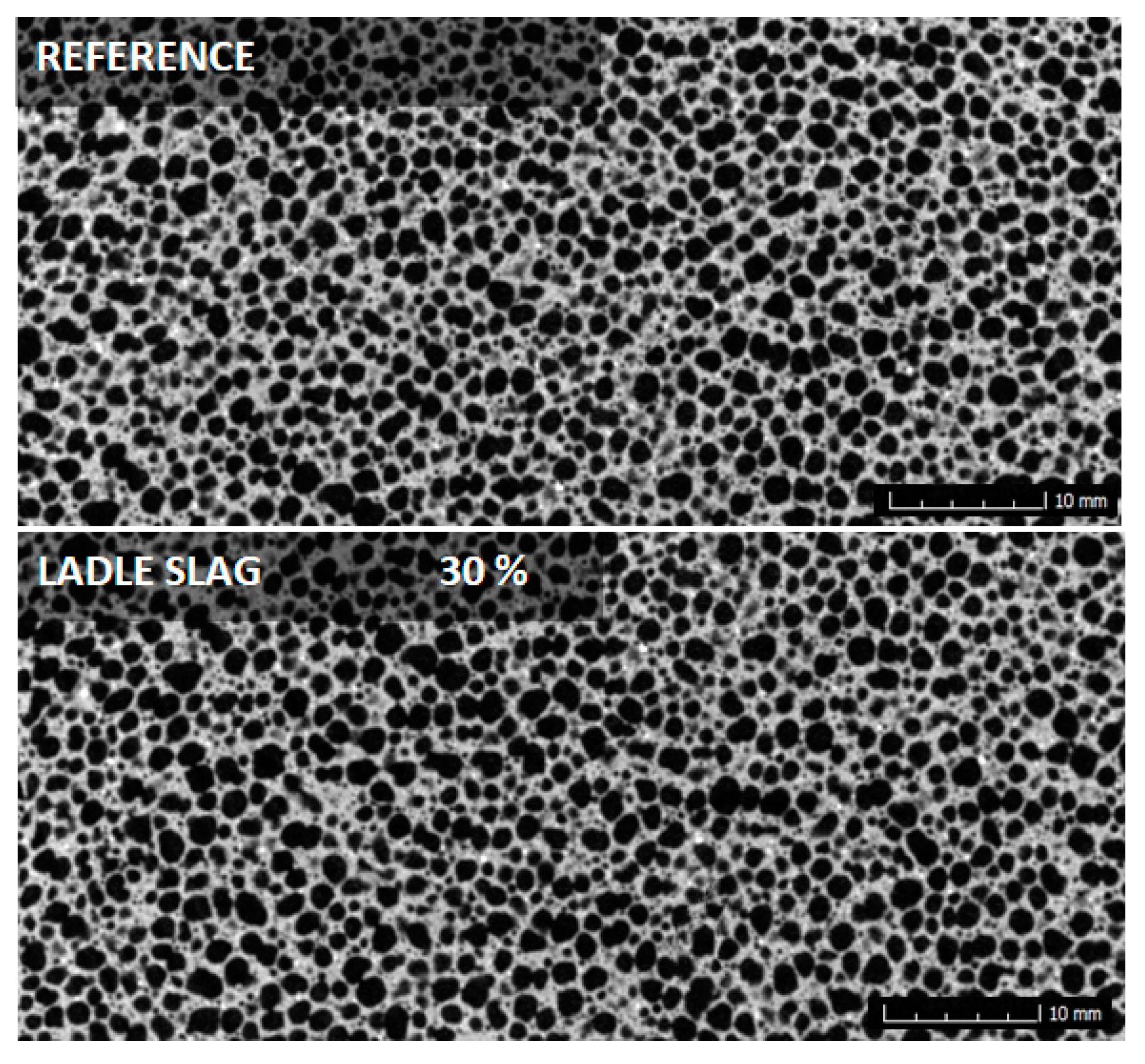
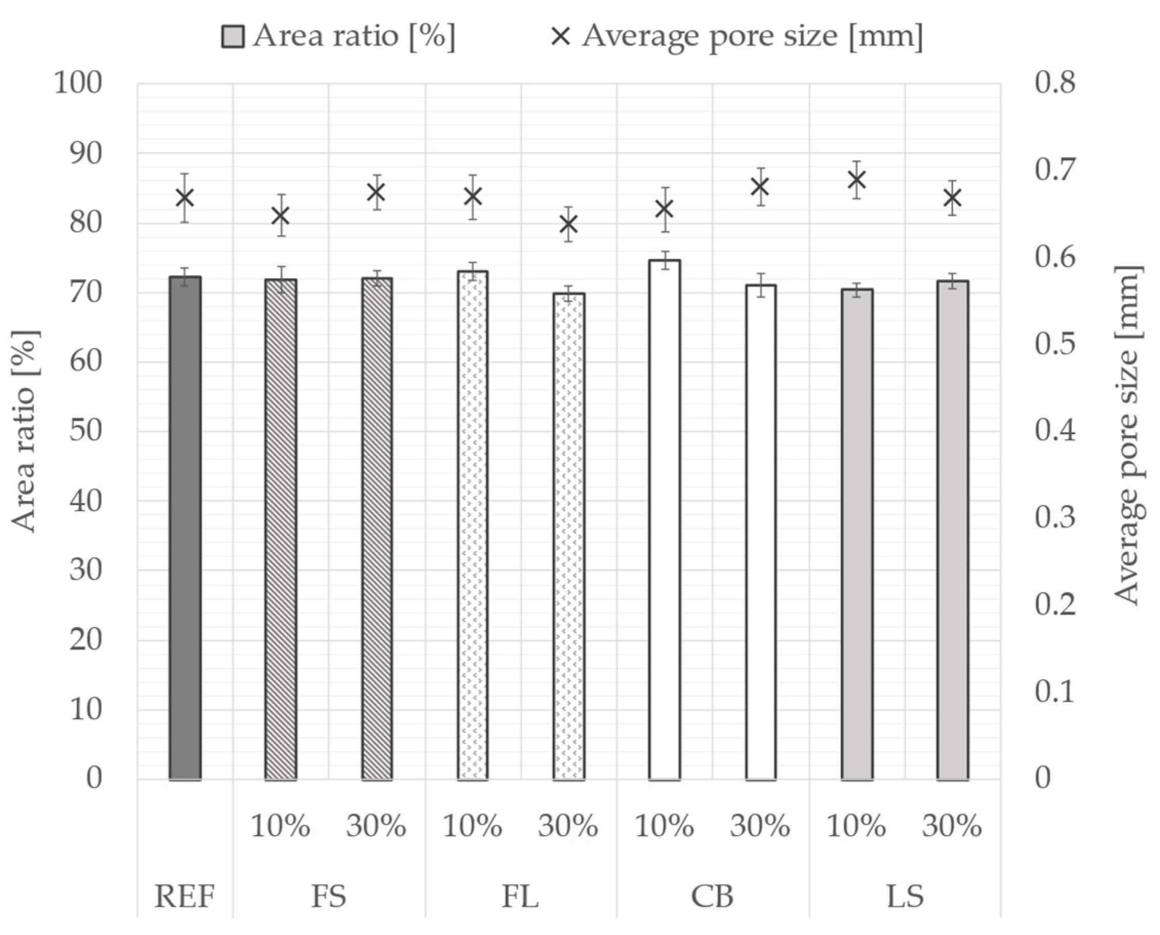
3.2. Distribution of Pores
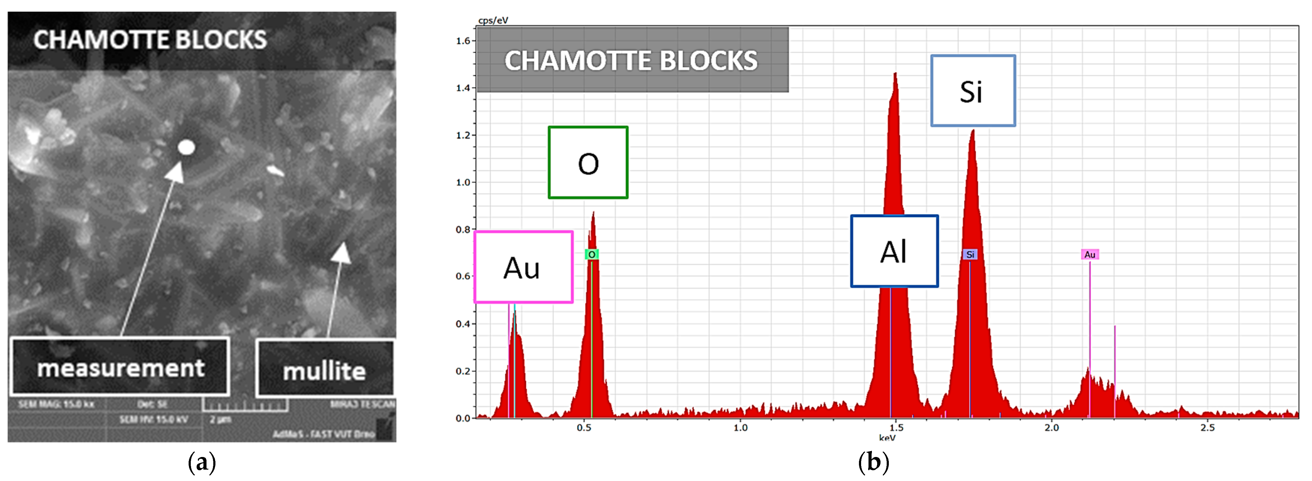
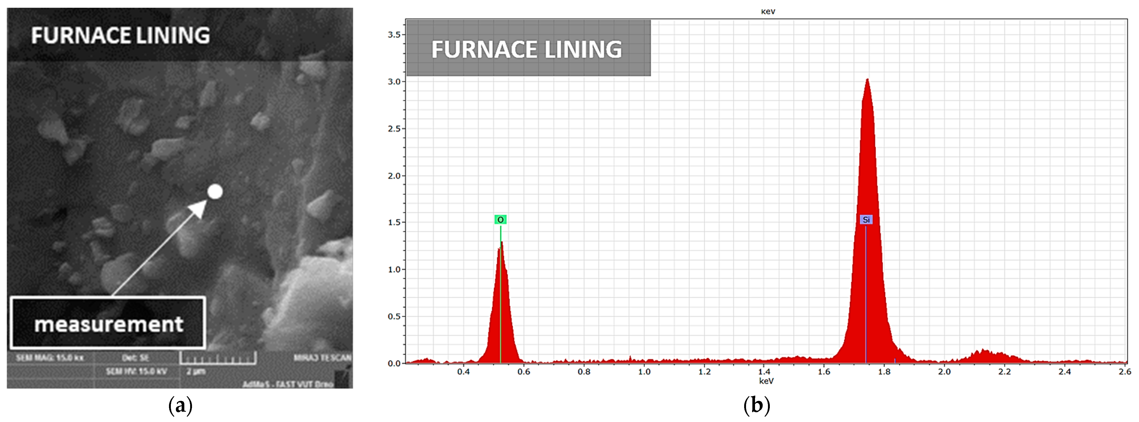
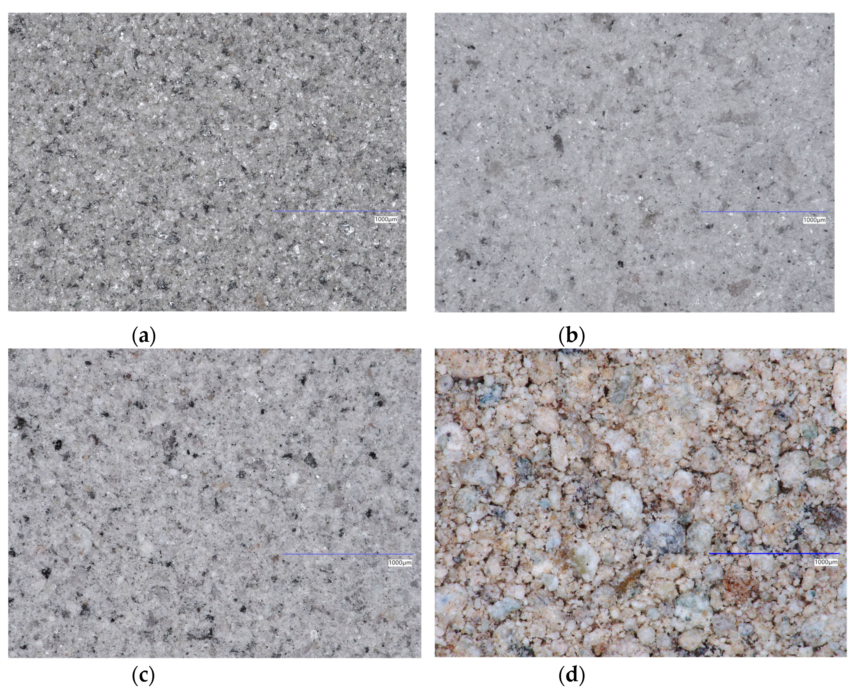
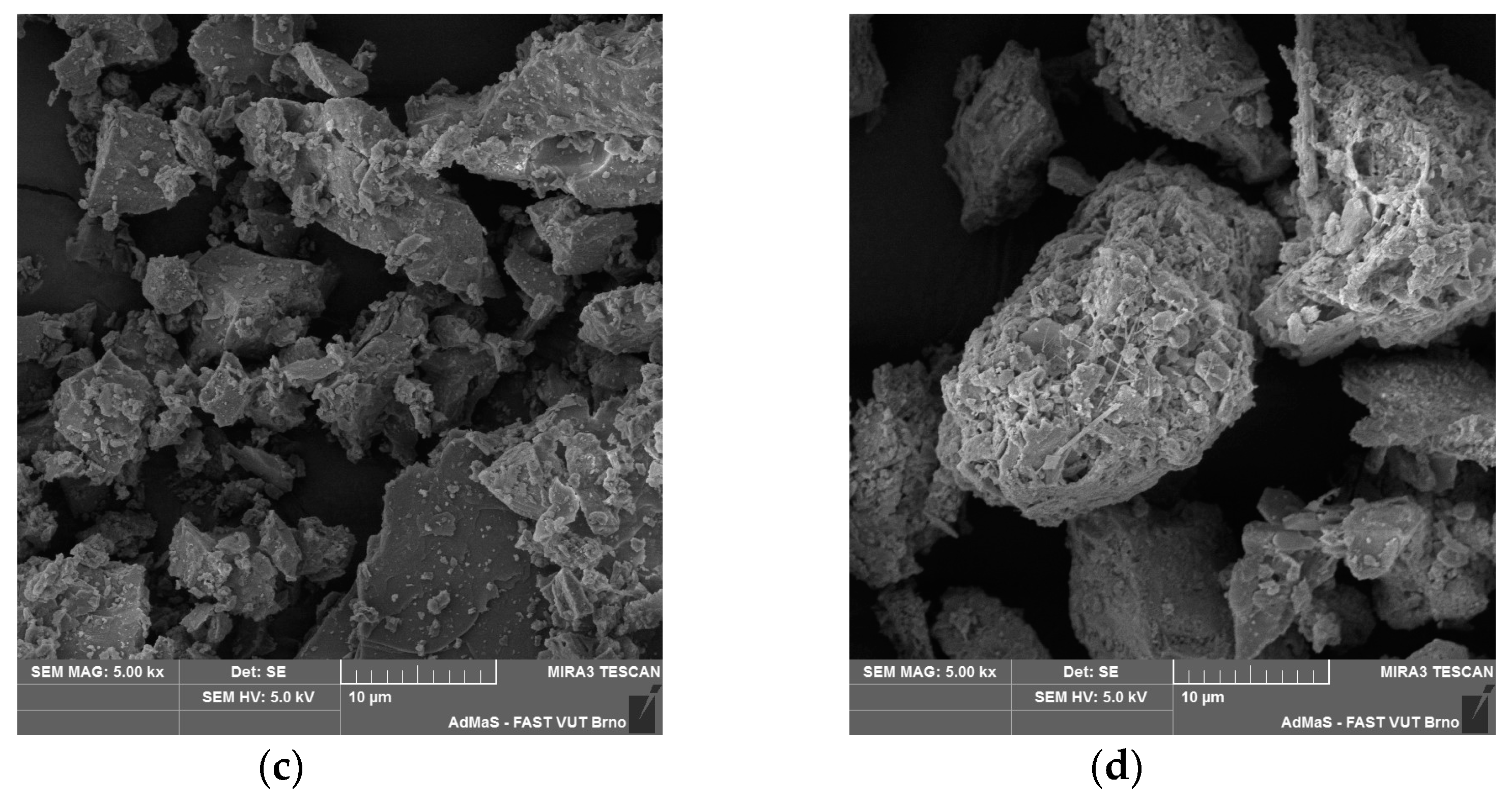
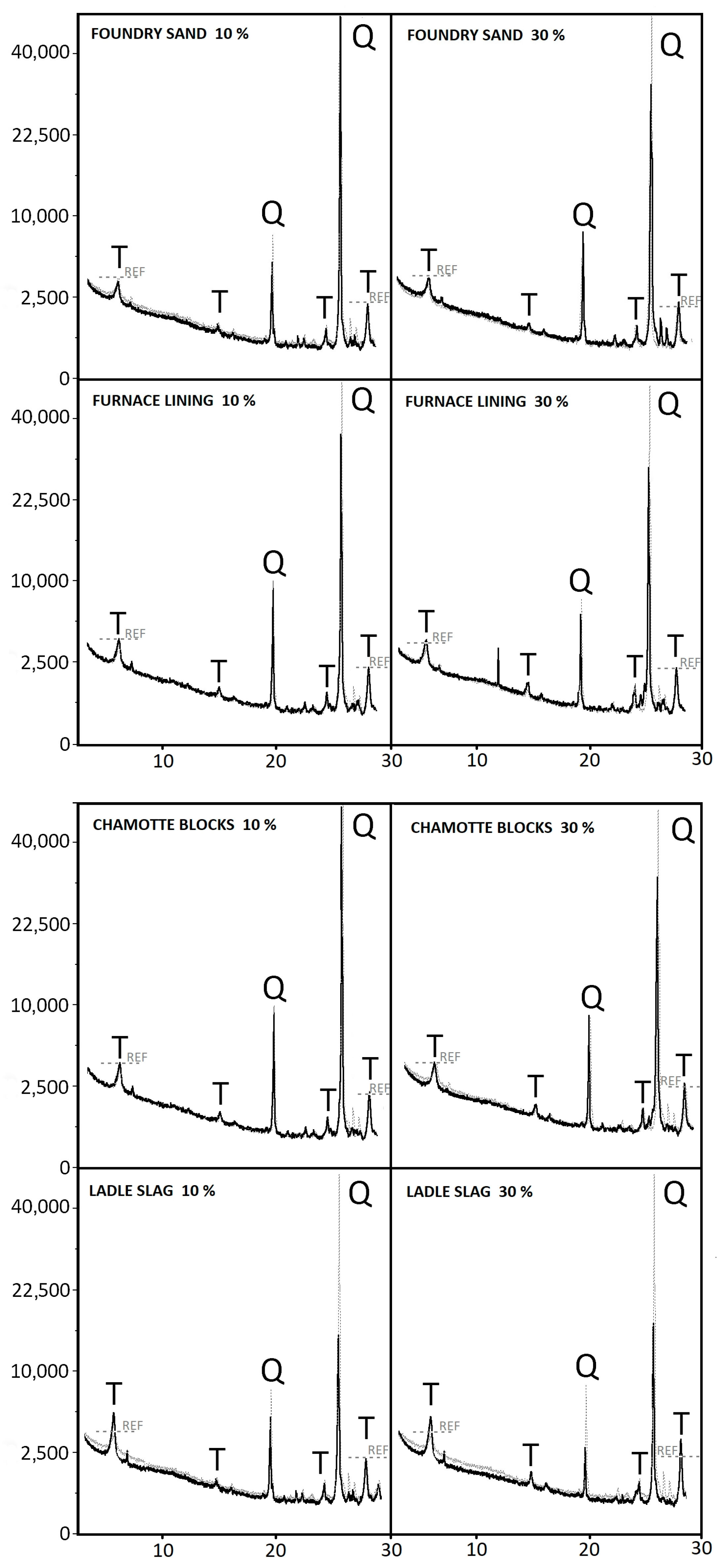
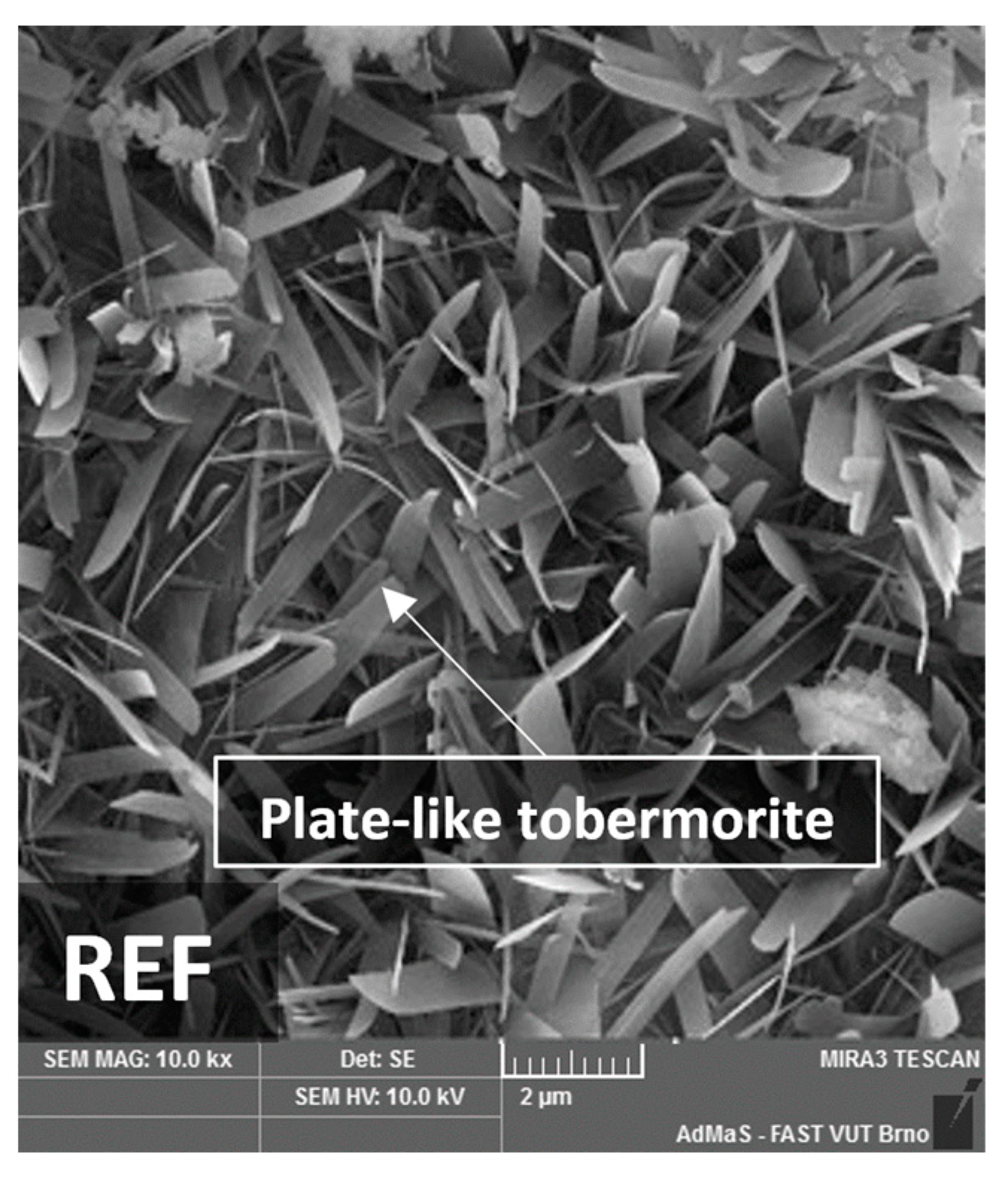
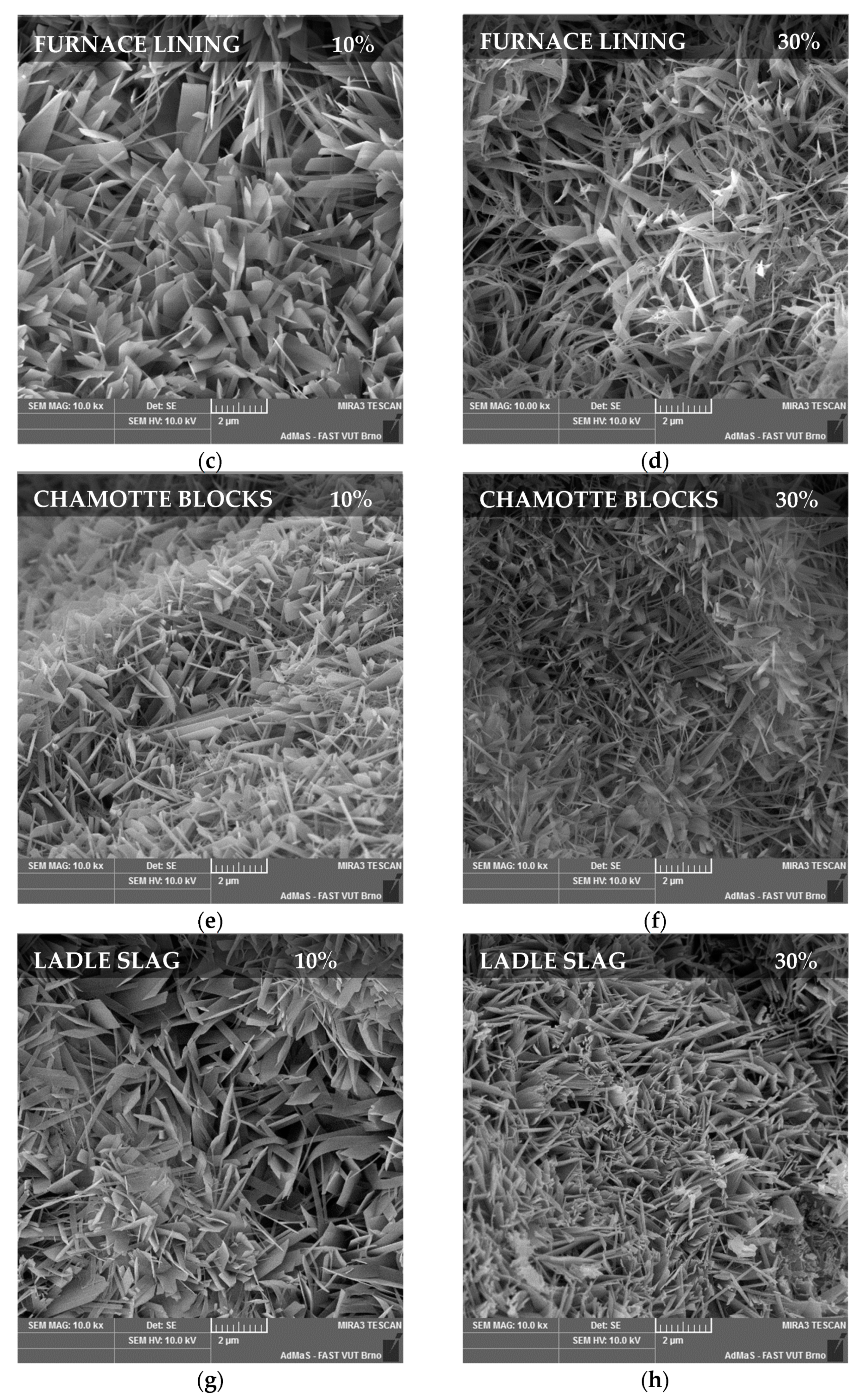
The internal structure of the material can significantly affect the physico-mechanical properties [34]; therefore, it was necessary to exclude the influences of the pore structure and possible defects. To determine the influence of used secondary raw materials on the distribution of pores, computed tomography was used. For illustrative purposes, two images of samples were selected (Figure 9). These two samples were specifically chosen for their most significant difference in the physical and mechanical properties. This comparison highlights the impact of varied properties of secondary raw materials on the overall performance of the AAC.
Figure 9 shows the reference sample and the sample with 30% of LS. The distribution of pores is similar in both images, and the sizes of the pores determined by CT range from 0.2 mm to 2 mm. The same parameters were observed in the other samples, too. The porous structure was formed during the aeration of the material and was influenced by many internal and external factors. The influence of external factors is minimal in this case as identical technology was used for preparation. At the stage of maturing, quartz sand creates a firm frame, and the function of a binder is provided by lime and cement [35]. The internal factors are different only in the case of the replacement of quartz sand with secondary raw material. The amount of mixing water used is one of the internal factors. As the secondary raw materials used have the same water absorbing capacity as quartz sand, the amount of water remained constant. At the same time, all samples had an almost identical consistency; therefore, the porous structure of all samples was similar (Figure 10).

3.3. Microstructure

As the previous studies proved, the microstructure of specimens has a certain influence on the mechanical properties of the samples [35]. The crystallization of tobermorite and its amount and shape in the sample are crucial [36,37]. The formation of tobermorite was studied by X-ray analysis (XRD), energy-dispersive X-ray analysis (EDX), and scanning electron microscopy (SEM).
A microstructural analysis was conducted to assess tobermorite crystallization, as this may be closely associated with the material’s strength. The X-ray images (Figure 11) show an almost identical intensity of the diffraction line of tobermorite in all samples. The intensity of tobermorite was different only for the sample with ladle slag. In the sample with ladle slag, tobermorite has the highest diffraction line, and quartz has the lowest diffraction line compared to the other samples. This is confirmed by the claim that quartz could react more with a higher calcium hydroxide concentration to form well-crystallized tobermorite. The intensity of the quartz peak corresponds directly to the quartz contents in the raw materials and reflects their proportion within the specific formulation.
The SEM result (Figure 12) confirms the formation of tobermorite in the reference sample. Crystals of tobermorite in the reference sample have a plate-like shape. The crystals are interlocked and form a regular structure.
The mixture with 10% FS (Figure 13a) contains crystals of plate-like tobermorite. If the proportion of replacement is higher (Figure 13b), the crystallization of tobermorite remains unchanged. According to this fact, it is not advantageous to use foundry sand in larger amounts due to its negative effect on the mechanical properties.
The mixture with 10% FL (Figure 13c) contains plate-like tobermorite similarly shaped as the tobermorite present in the reference mixture and has a slightly increased strength. Crystals of tobermorite were formed in the whole structure. The SEM image also shows a grain of quartz and CSH gel. The mixture with 30% FL (Figure 13d) contains tobermorite with longer and thinner crystals than those observed in the REF mixture. The change in the shape of tobermorite is caused by a high content of aluminum oxide in the furnace lining. It has been proven by studies that the formation of tobermorite is influenced by aluminum oxide. Al-substituted tobermorite is formed by long chains [3,38].
The mixture with 10% CB (Figure 13e) contains crystals of tobermorite which are wider compared to the REF samples. Chamotte blocks have a lower silica content than quartz sand, thus adding calcium-rich CSH gels. These gels form shorter chains that crystallize more easily, allowing larger tobermorite crystals to form [36]. The glass phase of the silica oxide is more soluble and promotes the crystallization of the CSH phases. In the mixture with 30% CB (Figure 13f), smaller needle-like crystals are formed. With an increasing content of chamotte blocks, the mixture contains a greater amount of reactive silica, and therefore, smaller tobermorite crystals are formed.
The SEM images show a change in the tobermorite shape in the mixtures with 10% (Figure 13g) and 30% LS (Figure 13h) compared to that in the reference sample. In the mixture with 10% LS (Figure 13g), the crystals of tobermorite are shorter, interlocked, and form a strong binding phase between grains of quartz. In the mixture with 30% LS (Figure 13h), well-crystallized tobermorite is formed in the form of “house of cards”, thanks to which it achieves greater strength [39].

4. Conclusions

Based on the obtained results, it can be concluded that furnace lining, chamotte blocks, and ladle slag from the metallurgical industry had a positive influence on the physical–mechanical properties of samples and their microstructures. Foundry sand slightly deteriorates the physico-mechanical properties of AAC. The following conclusions can be made:
  • Ladle slag increased the strength of the samples, even with 30% replacement, by up to 17.5% thanks to the content of CaO.
  • Furnace lining increased the strength of the samples by up to 15% because of the high content of aluminum oxide, which has a positive effect on the microstructure of the samples. This positive trend was observed even in the case of a higher substitution rate of 30%.
  • The influence of foundry sand on the strength and microstructure slightly deteriorated. This negative effect increased with an increasing amount of replacement.
  • Using chamotte blocks to replace quartz sand had a slightly positive effect on the strength of the samples.
  • Secondary raw materials from the metallurgical industry have a similar water absorbing capacity and therefore no impact on the distribution of pores.
This paper implies that secondary raw materials have great potential to be used in the technology for the production of sand aerated concrete.

Author Contributions

Conceptualization, L.M. and V.Č.; methodology, V.Č. and R.D.; formal analysis J.M., P.O. and V.Č.; investigation, L.M., P.O. and V.Č.; resources, L.M. and P.O.; data curation, J.M., V.Č. and R.D.; writing—original draft preparation, V.Č., R.D., P.O. and L.M.; writing—review and editing, L.M., V.Č., J.M. and R.D.; project administration, L.M.; visualization, V.Č. and J.M.; supervision, R.D.; funding acquisition, L.M. All authors have read and agreed to the published version of the manuscript.

Funding

This paper was created with the financial support of the Czech Science Foundation (GACR), standard project No. 23-04824S, “Influence of alternative raw material components on improvement of physico-mechanical properties of aerated autoclaved concrete”.

Data Availability Statement

Data are contained within the article.

Conflicts of Interest

The authors declare no conflicts of interest.

References

  1. Kanehira, S.; Kanamori, S.; Nagashima, K.; Saeki, T.; Visbal, H.; Fukui, T.; Hirao, K. Controllable hydrogen release via aluminum powder corrosion in calcium hydroxide solutions. J. Asian Ceram. Soc. 2013, 3, 296–303. [Google Scholar] [CrossRef]
  2. Mostafa, N.Y. Influence of air-cooled slag on physicochemical properties of autoclaved aerated concrete. Cem. Concr. Res. 2005, 35, 1349–1357. [Google Scholar] [CrossRef]
  3. Mitsuda, T.; Sasaki, K.; Ishida, H. Phase evolution during autoclaving process of aerated concrete. J. Am. Ceram. Soc. 1992, 75, 1858–1863. [Google Scholar] [CrossRef]
  4. Kikuma, J.; Tsunashima, M.; Ishikawa, T.; Matsuno, S.; Ogawa, A.; Matsui, K.; Sato, M. In situ time-resolved x-ray diffraction of tobermorite formation process under autoclave condition. J. Am. Ceram. Soc. 2010, 93, 2667–2674. [Google Scholar] [CrossRef]
  5. Matsui, K.; Kikuma, J.; Tsunashima, M.; Ishikawa, T.; Matsuno, S.; Ogawa, A.; Sato, M. In situ time-resolved x-ray diffraction of tobermorite formation in autoclaved aerated concrete: Influence of silica source reactivity and Al addition. Cem. Concr. Res. 2011, 41, 510–519. [Google Scholar] [CrossRef]
  6. Houston, J.R.; Maxwell, R.S.; Carroll, S.A. Transformation of meta-stable calcium silicate hydrates to tobermorite: Reaction kinetics and molecular structure from XRD and NMR spectroscopy. Geochem. Trans. 2009, 10, 1. [Google Scholar] [CrossRef]
  7. Al-Wakeel, E.I.; El-Korashy, S.A. Reaction mechanism of the hydrothermally treated CaO–SiO2–Al2O3 and CaO–SiO2–Al2O3–CaSO4 systems. J. Mater. Sci. 1996, 31, 1909–1913. [Google Scholar] [CrossRef]
  8. Dilnesa, B.Z.; Lothenbach, B.; Renaudin, G.; Wichser, A.; Kulik, D. Synthesis and characterization of hydrogarnet Ca3(AlxFe1−x)2(SiO4)y(OH)4(3−y). Cem. Concr. Res. 2014, 59, 96–111. [Google Scholar] [CrossRef]
  9. Siauciunas, R.; Smalakys, G.; Eisinas, A.; Prichockiene, E. Synthesis of High Crystallinity 1.13 nm Tobermorite and Xonotlite from Natural Rocks, Their Properties and Application for Heat-Resistant Products. Materials 2022, 15, 3474. [Google Scholar] [CrossRef] [PubMed] [PubMed Central]
  10. Melichar, T.; Bydžovský, J.; Dufka, Á. Composites based on alternative raw materials at high temperature conditions. Period. Polytech. Civ. Eng. 2017, 61, 911–919. [Google Scholar] [CrossRef]
  11. Melichar, T.; Bydžovský, J. Study of the parameters of lightweight polymer- cement repair mortars exposed to high temperatures. Appl. Mech. Mater. 2013, 395, 429–432. [Google Scholar] [CrossRef]
  12. Zach, J.; Sedlmajer, M.; Dufek, Z.; Bubeník, J. Development of light-weight concrete with utilization of foam glass based aggregate. Solid State Phenom. 2018, 276, 276–281. [Google Scholar] [CrossRef]
  13. Kunchariyakun, K.; Asavapisit, S.; Sombatsompop, K. Properties of autoclaved aerated concrete incorporating rice husk ash as partial replacement for fine aggregate. Cem. Concr. Compos. 2015, 55, 11–16. [Google Scholar] [CrossRef]
  14. Siddique, R.; Schutter, G.; Noumowe, A. Effect of used-foundry sand on the mechanical properties of concrete. Constr. Build. Mater. 2009, 23, 976–980. [Google Scholar] [CrossRef]
  15. Guney, Y.; Aydilek, A.H.; Demirkan, M.M. Geoenvironmental behavior of foundry sand amended mixtures for highway subbases. Waste Manag. 2006, 26, 932–945. [Google Scholar] [CrossRef] [PubMed]
  16. Siddique, R.; Noumowe, A. Utilization of spent foundry sand in controlled low-strength materials and concrete. Resour. Conserv. Recycl. 2008, 53, 27–35. [Google Scholar] [CrossRef]
  17. Guney, Y.; Sari, Y.D.; Yalcin, M.; Tuncan, A.; Donmez, S. Re-usage of waste foundry sand in high-strength concrete. Waste Manag. 2010, 30, 1705–1713. [Google Scholar] [CrossRef]
  18. Aggarwal, Y.; Siddique, R. Microstructure and properties of concrete using bottom ash and waste foundry sand as partial replacement of fine aggregates. Constr. Build. Mater. 2014, 54, 210–223. [Google Scholar] [CrossRef]
  19. Jančara, D.; Tvardek, P.; Hašek, P. Pouring ladles in acelormital Ostrava steel plant utilization of new insulation layer. Met. Hradec Moravicí 2008, 6, 13–15. [Google Scholar]
  20. Adolf, Z.; Suchánek, P.; Husa, I. The infuence of carbon content on the corrosion of mgo-c refractory material caused by acid and alkaline ladle slag, SLAG. Mater. Technol. 2008, 42, 131–133. [Google Scholar]
  21. Wang, L.; Jin, M.; Zhou, S.; Tang, S.; Lu, X. Investigation of microstructure of C-S-H and micro-mechanics of cement pastes under NH4NO3 dissolution by 29Si MAS NMR and microhardness. Measurement 2021, 185, 110019. [Google Scholar] [CrossRef]
  22. Bernard, V.A.R.; Renuka, S.M.; Avudaiappan, S.; Umarani, C.; Amran, M.; Guindos, P.; Fediuk, R.; Vatin, N.I. Performance Investigation of the Incorporation of Ground Granulated Blast Furnace Slag with Fly Ash in Autoclaved Aerated Concrete. Crystals 2022, 12, 1024. [Google Scholar] [CrossRef]
  23. Yang, W.; Zhang, L.; Wang, X.; Ren, Y.; Liu, X.; Shan, Q. Characteristics of inclusions in low carbon Al-killed steel during ladle furnace refining and calcium treatment. ISIJ Int. 2013, 53, 1401–1410. [Google Scholar] [CrossRef]
  24. Xusheng, D.; Zhe, X.; Junjiang, L.; Lei, W. Effects of lime content on properties of autoclaved aerated concrete made from circulating fluidized bed ash. Dev. Built Environ. 2024, 18, 100406. [Google Scholar] [CrossRef]
  25. Kurdowski, W. The Properties of Cement Paste. In Cement and Concrete Chemistry; Springer: Dordrecht, The Netherlands, 2014. [Google Scholar] [CrossRef]
  26. Tsuji, M.; Komarneni, S.; Malla, P. Substituted tobermorites: 27Al and 29Si MASNMR, cation exchange, and water sorption studies. J. Am. Ceram. Soc. 1991, 72, 274–279. [Google Scholar] [CrossRef]
  27. Rios, C.; Williams, C.; Fullen, M. Hydrothermal synthesis of hydrogarnet and tobermorite at 175 °C from kaolinite and metakaolinite in the CaO–Al2O3–SiO2–H2O system: A comparative study. Appl. Clay Sci. 2009, 43, 228–237. [Google Scholar] [CrossRef]
  28. Mostafa, N.Y.; Shaltout, A.; Omar, H.; Abo-El-Enein, S.A. Hydrothermal synthesis and characterization of aluminium and sulfate substituted 1.1nm tobermorites. J. Alloys Compd. 2009, 467, 332–337. [Google Scholar] [CrossRef]
  29. Isu, N.; Ishida, H.; Mitsuda, T. Influence of quartz particle size on the chemical and mechanical properties of autoclaved aerated concrete (I) tobermorite formation. Cem. Concr. Res. 1995, 25, 243–248. [Google Scholar] [CrossRef]
  30. Tchadjie, L.N.; Ekolu, S.O. Enhancing the reactivity of aluminosilicate materials toward geopolymer synthesis. J. Mater. Sci. 2018, 53, 4709–4733. [Google Scholar] [CrossRef]
  31. Melichar, J.; Černý, V.; Fleischhacker, J.; Drochytka, R. Content of Aluminium Hydroxide in Lime-Silica Composite and its Influence on Tobermorite Formation. In Materials Science Forum; Trans Tech Publications: Bäch, Switzerland, 2018; pp. 195–199. ISSN 0255-5476. [Google Scholar]
  32. Baltakys, K.; Siauciunas, R. The influence of γ-Al2O3 and Na2O on the formation of calcium silicate hydrates in the CaO-quartz-H2O system. Mater. Sci.-Pol. 2007, 25, 185–198. [Google Scholar]
  33. Oh, J.E.; Clark, S.M.; Monteiro, P.J.M. Does the Al substitution in C-S-H (I) change its mechanical property? Cem. Concr. Res. 2011, 41, 102–106. [Google Scholar] [CrossRef]
  34. Abhilasha; Kumar, R.; Lakhani, R.; Mishra, R.K.; Khan, S. Utilization of Solid Waste in the Production of Autoclaved Aerated Concrete and Their Effects on its Physio-mechanical and Microstructural Properties: Alternative Sources, Characterization, and Performance Insights. Int. J. Concr. Struct. Mater. 2023, 17, 6. [Google Scholar] [CrossRef]
  35. Fan, J.; Cao, D.; Jing, Z.; Zhang, Y.; Pu, L.; Jing, Y. Synthesis and microstructure analysis of autoclaved aerated concrete with carbide slag addition. J. Wuhan Univ. Technol. Mater. Sci. Ed. 2014, 29, 1005–1010. [Google Scholar] [CrossRef]
  36. Alexanderson, J. Relations between structure and mechanical properties of autoclaved aerated concrete. Cem. Concr. Res. 1979, 9, 507–514. [Google Scholar] [CrossRef]
  37. Reinik, J.; Heinmaa, I.; Mikkola, J.P.; Kirso, U. Hydrothermal alkaline treatment of oil shale ash for synthesis of tobermorites. Fuel 2007, 86, 669–676. [Google Scholar] [CrossRef]
  38. Kalousek, G.L. Crystal chemistry of hydrous calcium silicates: I, substitution of aluminum in lattice of tobermorite. J. Am. Ceram. Soc. 1957, 40, 74–80. [Google Scholar] [CrossRef]
  39. Chucholowski, C.; Holger, M.; Thienel, K. Improving the recyclability, environmental compatibility, and CO2 balance of autoclaved aerated concrete by replacing sulfate carrier and cement with calcined clays. Ce/papers 2018, 4, 503–512. [Google Scholar] [CrossRef]
Figure 1. Chamotte blocks: (a) SEM image of analyzed area with magnification of 15,000×. (b) Elemental analysis of chamotte waste sample.
Buildings 14 03155 g001
Figure 2. Furnace lining: (a) SEM image of analyzed area with magnification of 15,000×. (b) Elementary analysis of furnace lining sample.
Buildings 14 03155 g002
Figure 3. Grain sizes of secondary raw materials and quartz sand before grinding.
Buildings 14 03155 g003
Figure 4. Grain size of secondary raw materials and quartz sand after grinding.
Buildings 14 03155 g004
Figure 5. Digital microscope images (magn. 100×) of used secondary raw materials after processing: (a) foundry sand; (b) furnace lining; (c) chamotte blocks; and (d) ladle slag.
Buildings 14 03155 g005
Figure 6. SEM images (magnification 5000×) of used secondary raw materials after processing: (a) foundry sand; (b) furnace lining; (c) chamotte blocks; and (d) ladle slag.
Buildings 14 03155 g006aBuildings 14 03155 g006b
Figure 7. Autoclaving parameters.
Buildings 14 03155 g007
Figure 8. Compressive strength (a) and bulk density (b) of samples with admixture of foundry sand, waste furnace lining, chamotte blocks, and ladle slag.
Buildings 14 03155 g008
Figure 9. Pore structures of reference sample and sample with 30% of siliceous component replacement with LS.
Buildings 14 03155 g009
Figure 10. Pore distribution of reference sample and sample with 30% admixture of furnace lining.
Buildings 14 03155 g010
Figure 11. X-ray images of samples with 10% and 30% admixture of sand with secondary materials (black curve) and reference sample (gray curve); tobermorite peak of intensity of reference sample is indicated by gray line.
Buildings 14 03155 g011
Figure 12. SEM image of reference sample autoclaved for 8 h with isothermal dwelling at 190 °C.
Buildings 14 03155 g012
Figure 13. SEM image of samples with 10% and 30% admixture with secondary raw materials at magnification of 10,000×: (a) 10% foundry sand, (b) 30% foundry sand, (c) 10% furnace lining, (d) 30% furnace lining, (e) 10% chamotte blocks, (f) 30% chamotte blocks, (g) 10% ladle slag, and (h) 30% ladle slag.
Buildings 14 03155 g013aBuildings 14 03155 g013b
Table 1. Chemical compositions and mineralogical compositions of primary raw materials.
Chemical CompositionMineralogical Composition
SiO2 [%]SO4(2−) [%]Al2O3 [%]CaO [%]Fe2O3 [%]K2O [%]Na2O [%]
Quartz sand92.910.022.530.230.841.530.7quartz
Cement19.672.665.464.253.063.320.36C3S, C2S, C3A, C4AF
Lime-0.07-95.62---lime
Table 2. Chemical compositions and mineralogical compositions of secondary raw materials.
Chemical CompositionMineralogical Composition
SiO2 [%]SO4(2−) [%]Al2O3 [%]CaO [%]Fe2O3 [%]K2O [%]Na2O [%]
Foundry sand (FS)82.70.11.510.32.630.450.23quartz
Furnace lining (FL)56.10.1732.40.42.381.140.12quartz,
mullite,
cristoballite
Chamotte blocks (CB)63.80.1423.21.181.660.950.25quartz,
mullite,
cristobalite, corundum
Ladle slag (LS)15.8<0.1013.430.72.20.240.19lime, C2S,
calcite,
magnetite, hematite,
hydrocalumite
Table 3. Physical properties of raw materials.
Physical Properties
Density
[g·cm−3]
Specific Surface Area [cm2·g−1]Water Absorbency [%]
Primary raw materials
Quartz sand (QS)2.74282031
Secondary raw materials
Foundry sand (FS)2.86260027
Furnace lining (FL)2.73300036
Chamotte blocks (CB)2.75295033
Ladle slag (LS)2.92263037
Table 4. Mix designs of samples with 10% and 30% admixtures of sand with secondary raw materials.
Mix Designs [wt%]
Raw MaterialsREFReplacement of Siliceous Component
10%30%
Lime888
Cement141414
Gypsum333
Aluminum powder0.060.060.06
Quartz sand7467.351.8
Secondary raw materials06.722.2
Disclaimer/Publisher’s Note: The statements, opinions and data contained in all publications are solely those of the individual author(s) and contributor(s) and not of MDPI and/or the editor(s). MDPI and/or the editor(s) disclaim responsibility for any injury to people or property resulting from any ideas, methods, instructions or products referred to in the content.

