
Investigation on the Bearing Performance of a Single Pile in Shallow Reinforced Soft Soil Foundation under Horizontal Load

Abstract
1. Introduction
2. Finite Element Model Establishment
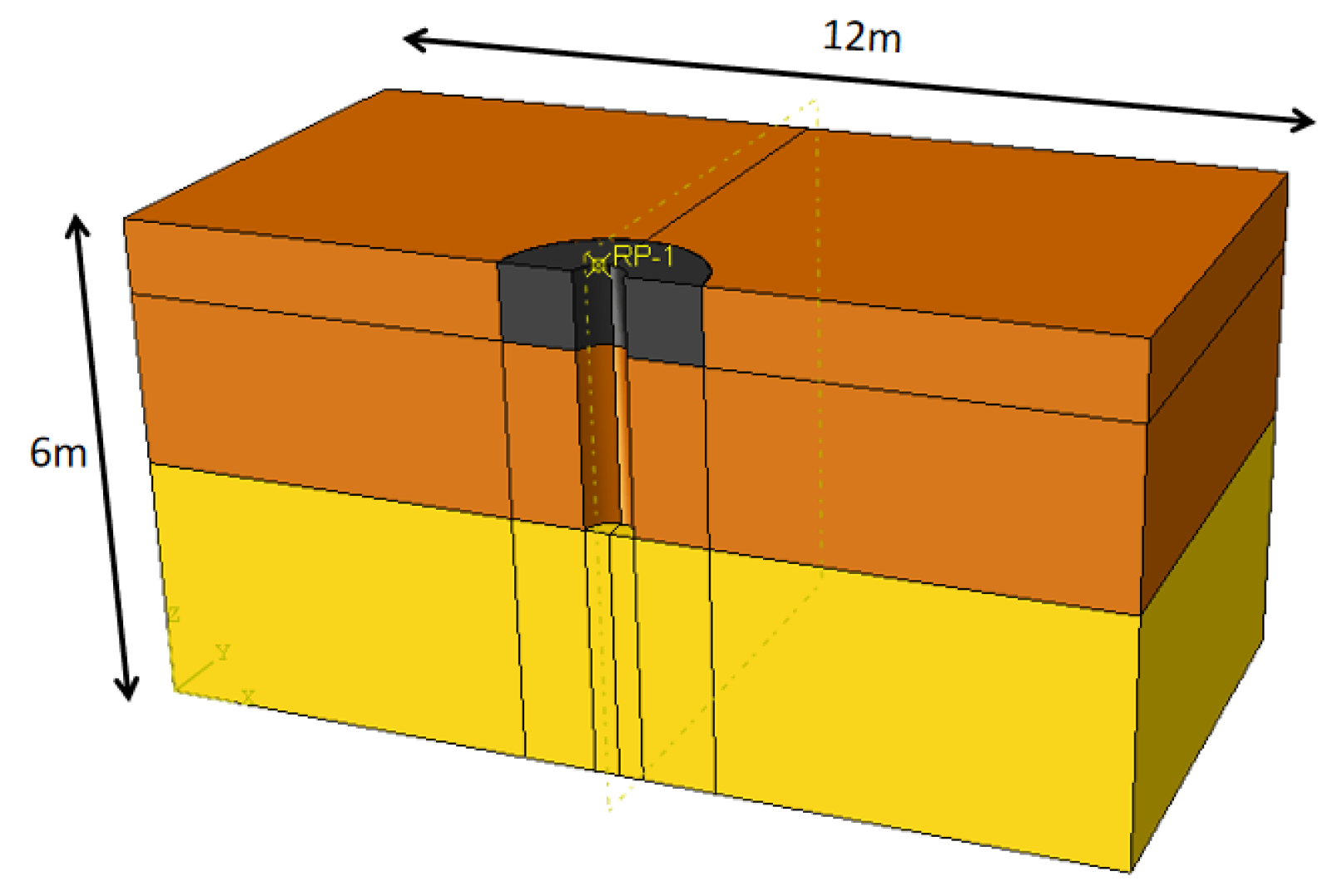
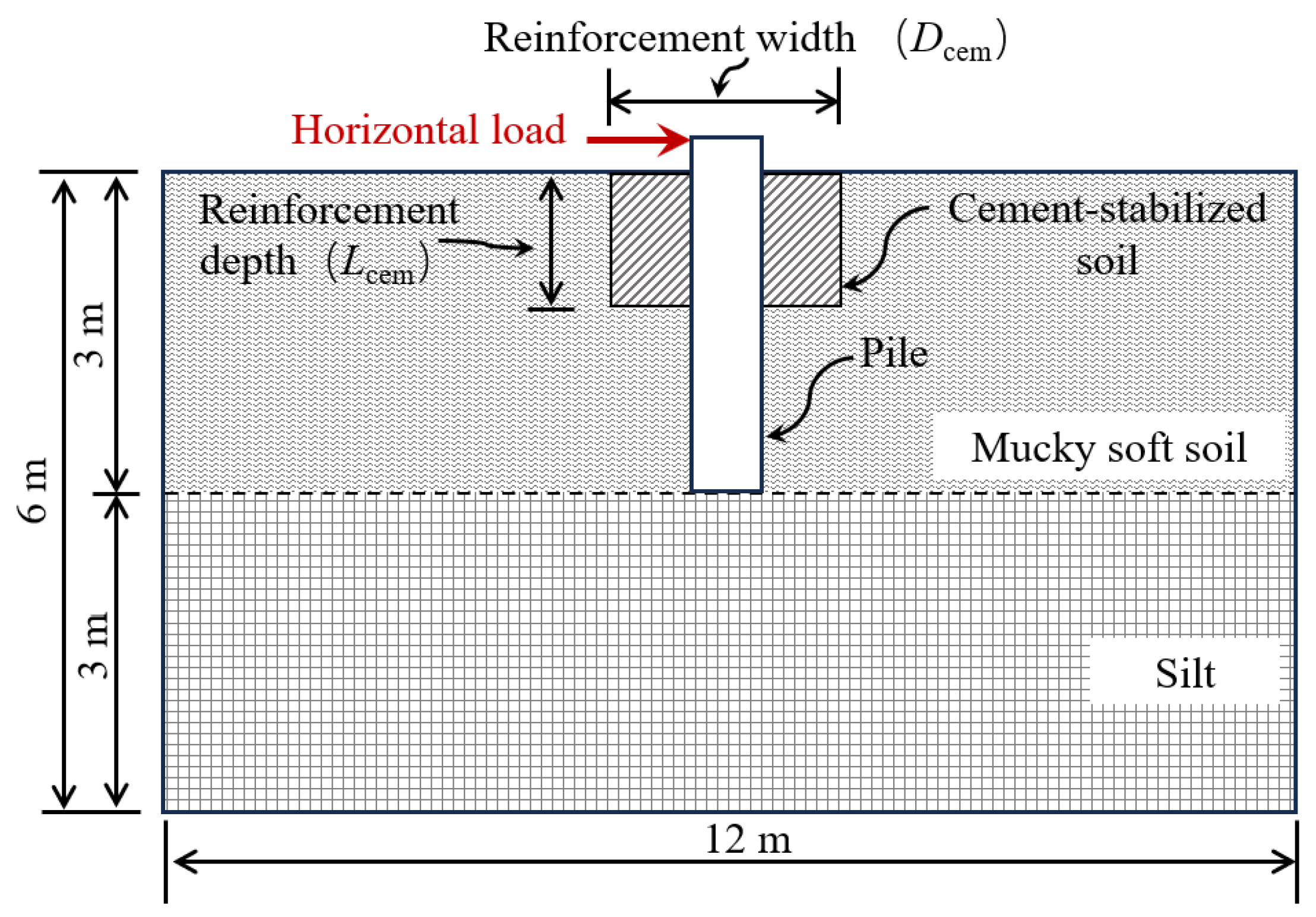
2.1. Model Design
- (1)
- Soil around the Pile
- (2)
- Pile
2.2. Simulation Groups
- (1)
- Variation in Reinforcement Width
- (2)
- Variation in Reinforcement Depth
2.3. Element Selection and Material Definition
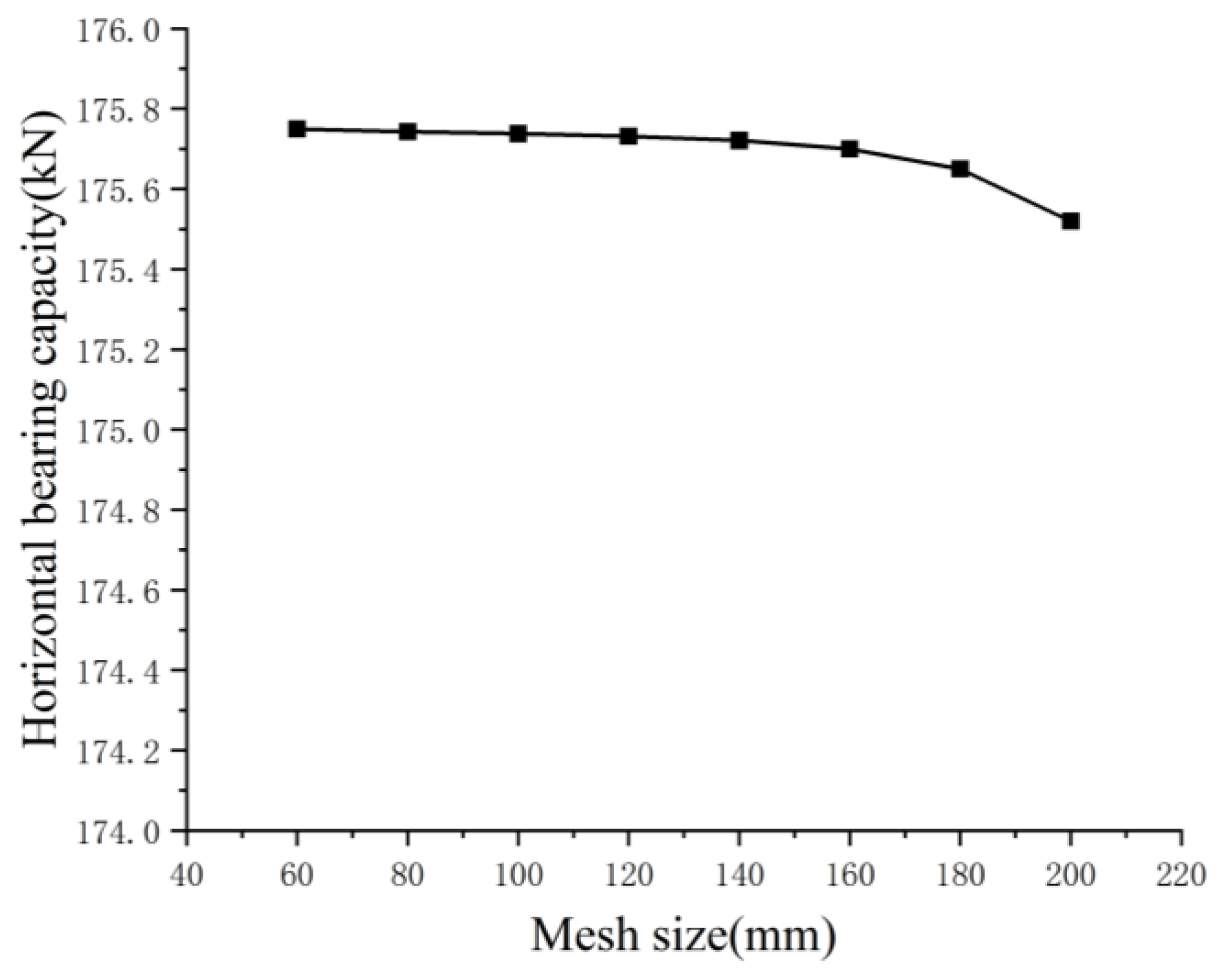
2.4. Meshing
2.5. Contact Definition and Boundary Conditions
2.6. Load Application and Control
2.7. Validation of Finite Element Simulation
3. Results and Analysis
3.1. The Influence of Reinforcement Width
- (1)
- Pile Bending Moment
- (2)
- Pile Displacement
- (3)
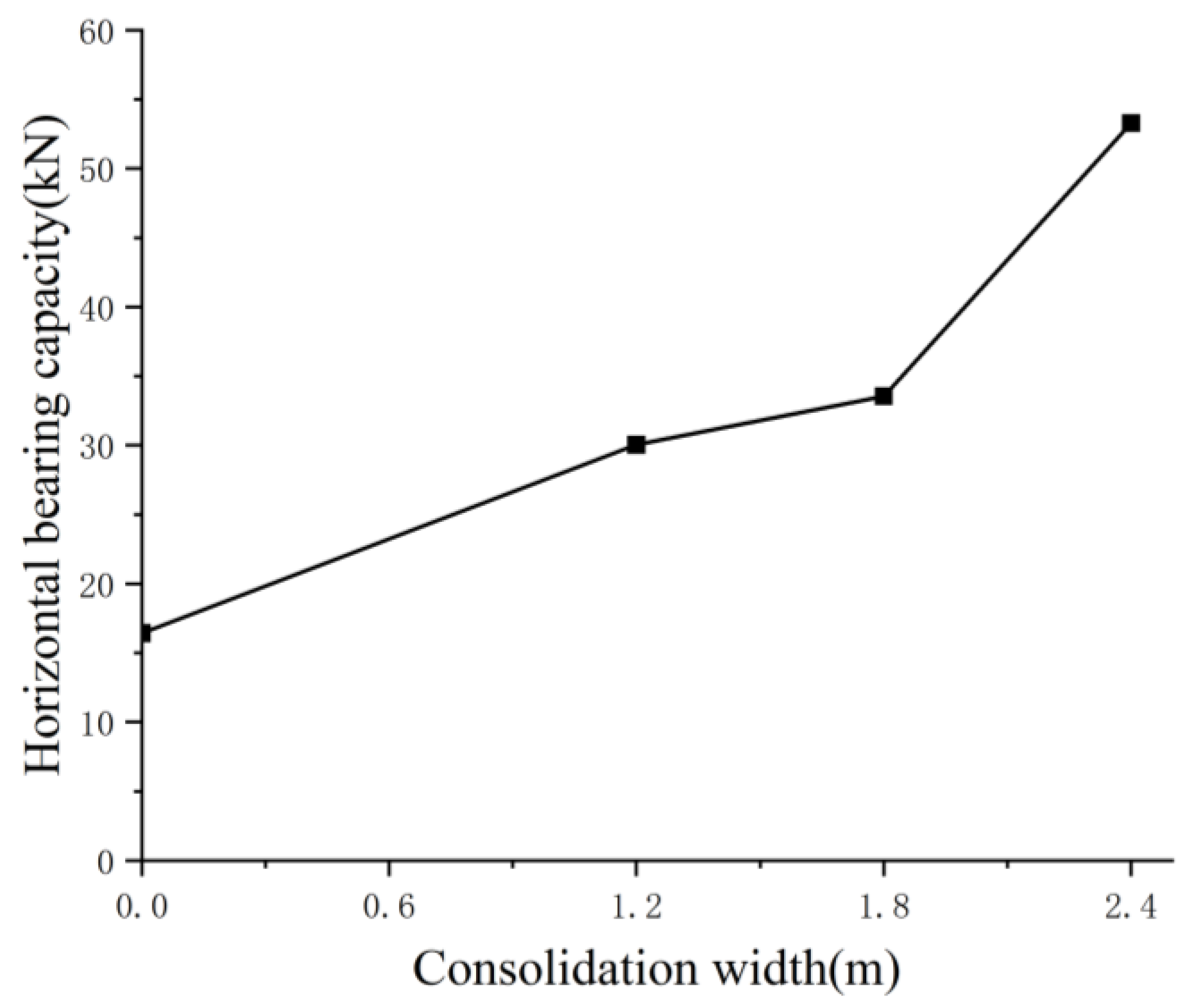
- Pile Horizontal Bearing Capacity
3.2. The Impact of Reinforcement Depth
- (1)
- Pile Bending Moment
- (2)
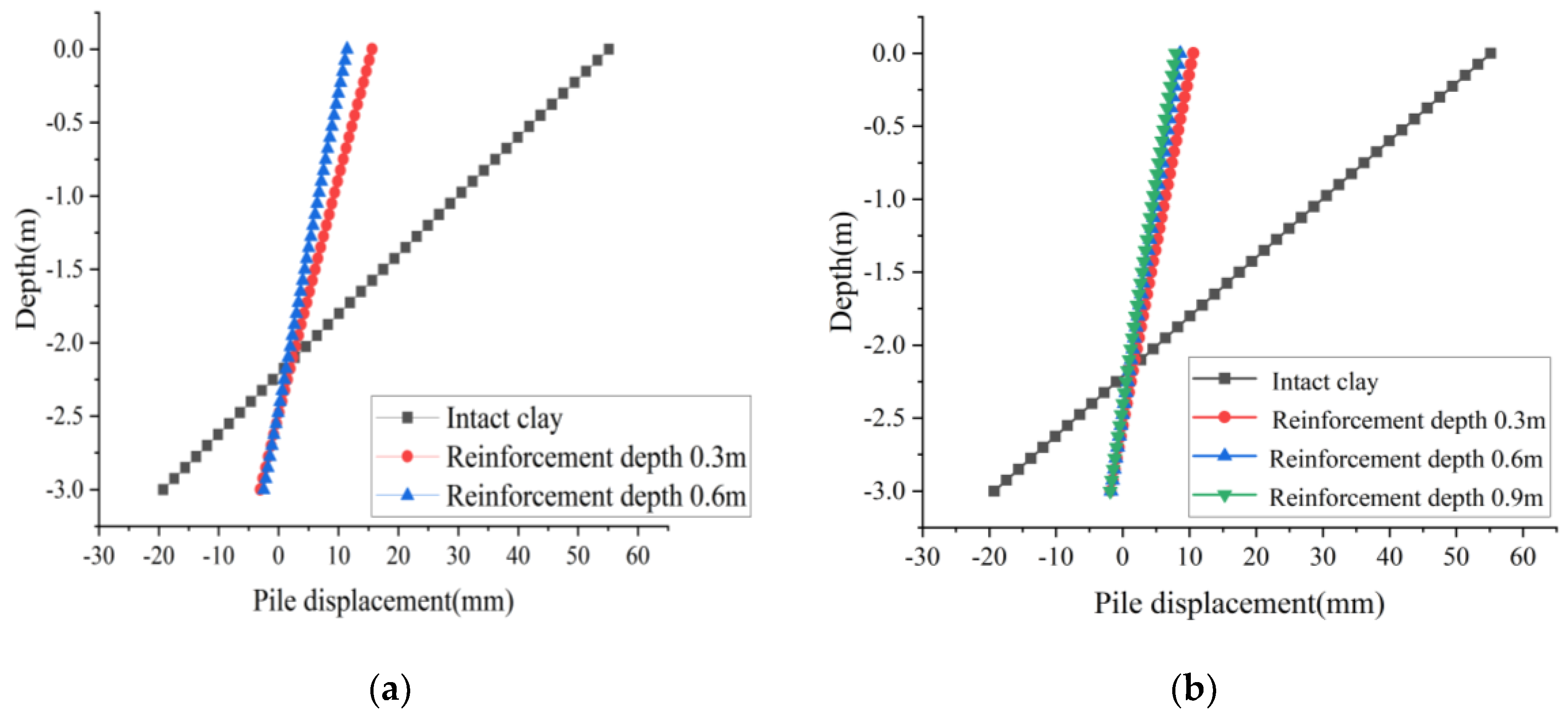
- Pile Displacement
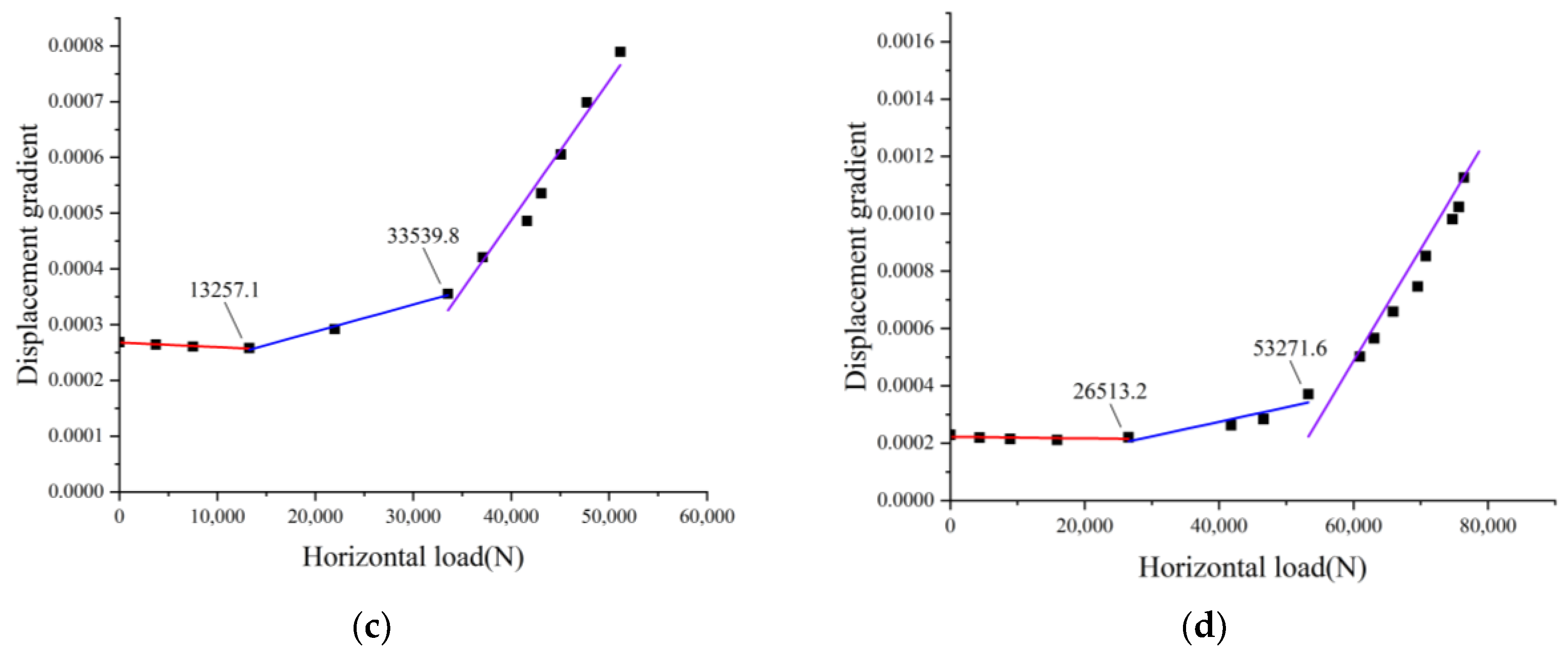
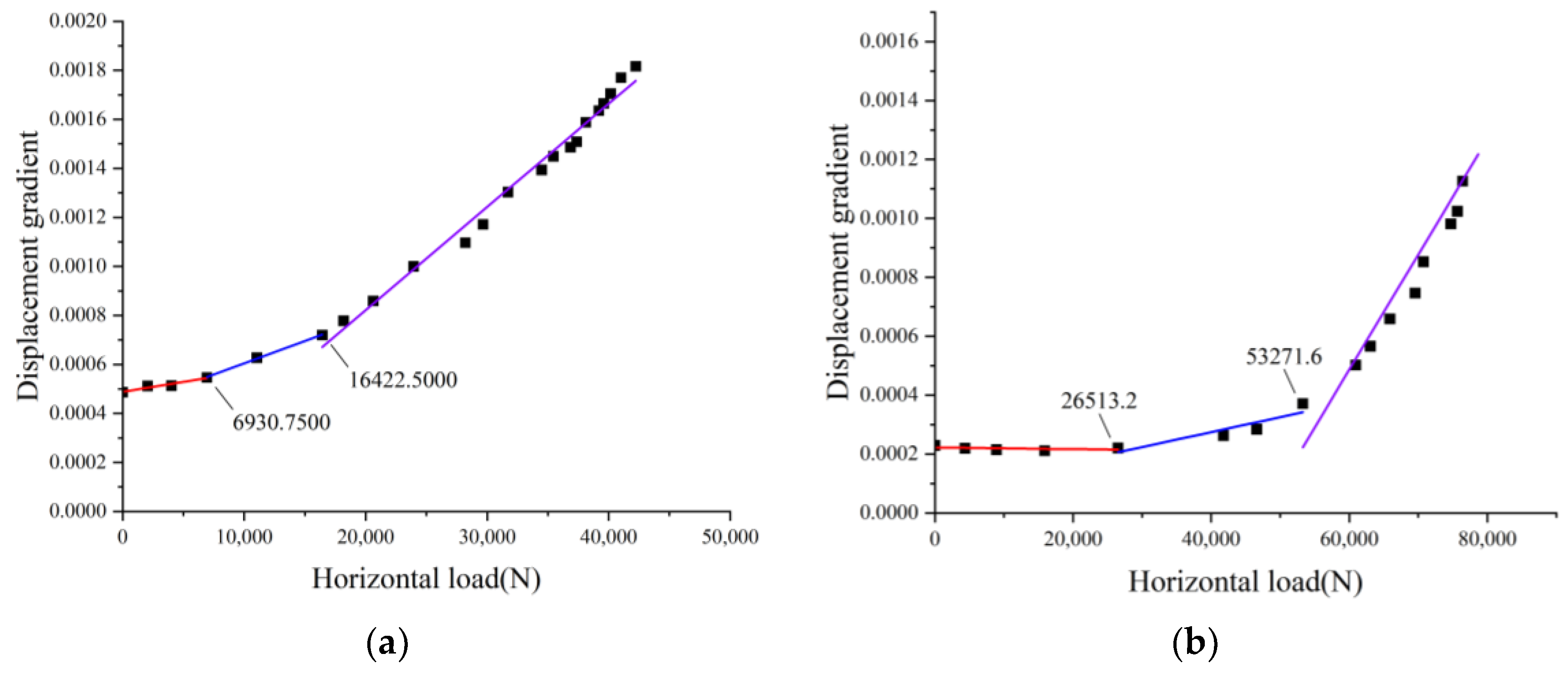
- (3)
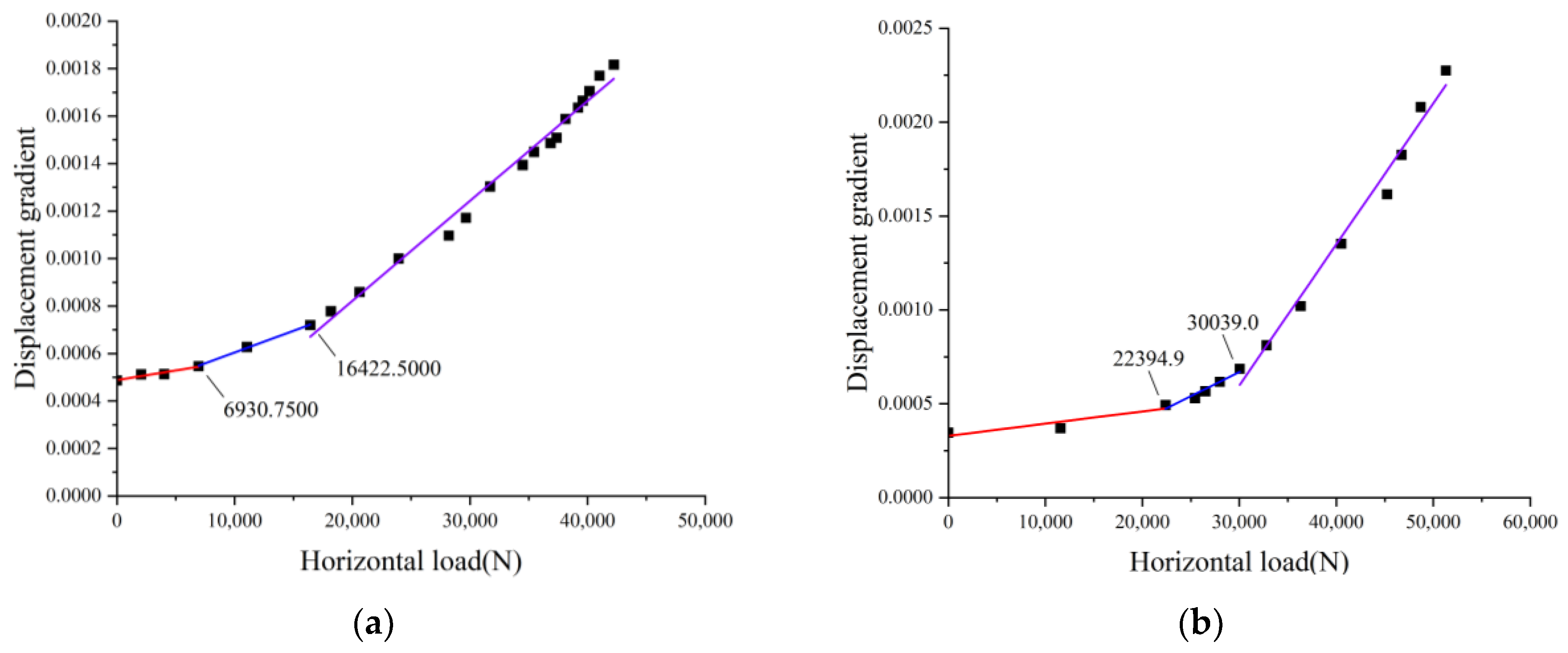
- Displacement Gradient
4. Conclusions
- (1)
- The comparison between the simulation carried out in this paper and the field test on the capacities of a single pile in shallow reinforcement soil showed good coincide, with a minimum relative error of 5.53%, a maximum error of 15.05%, and an average error of 9.35%. The simulation method proposed in this paper is suitable for analyzing the coupling bearing mechanism of piles in soft soil considering shallow reinforcement.
- (2)
- Increasing the reinforcement width can significantly improve the bearing capacity of the pile foundation, and as the reinforcement width increases, the reinforcement effect will become better and better. Compared with the unreinforced case, the horizontal bearing capacity of the pile is increased by 83.0%, 104.3%, and 224.4%, respectively, corresponding to a reinforcement width of 2 times, 3 times, or 4 times the dimeter of the pile respectively. With the increase of the reinforcement width, the bending moment and deformation of the pile under the same horizontal load decrease significantly, while also having no significant effect on the location of the maximum bending moment of the pile.
- (3)
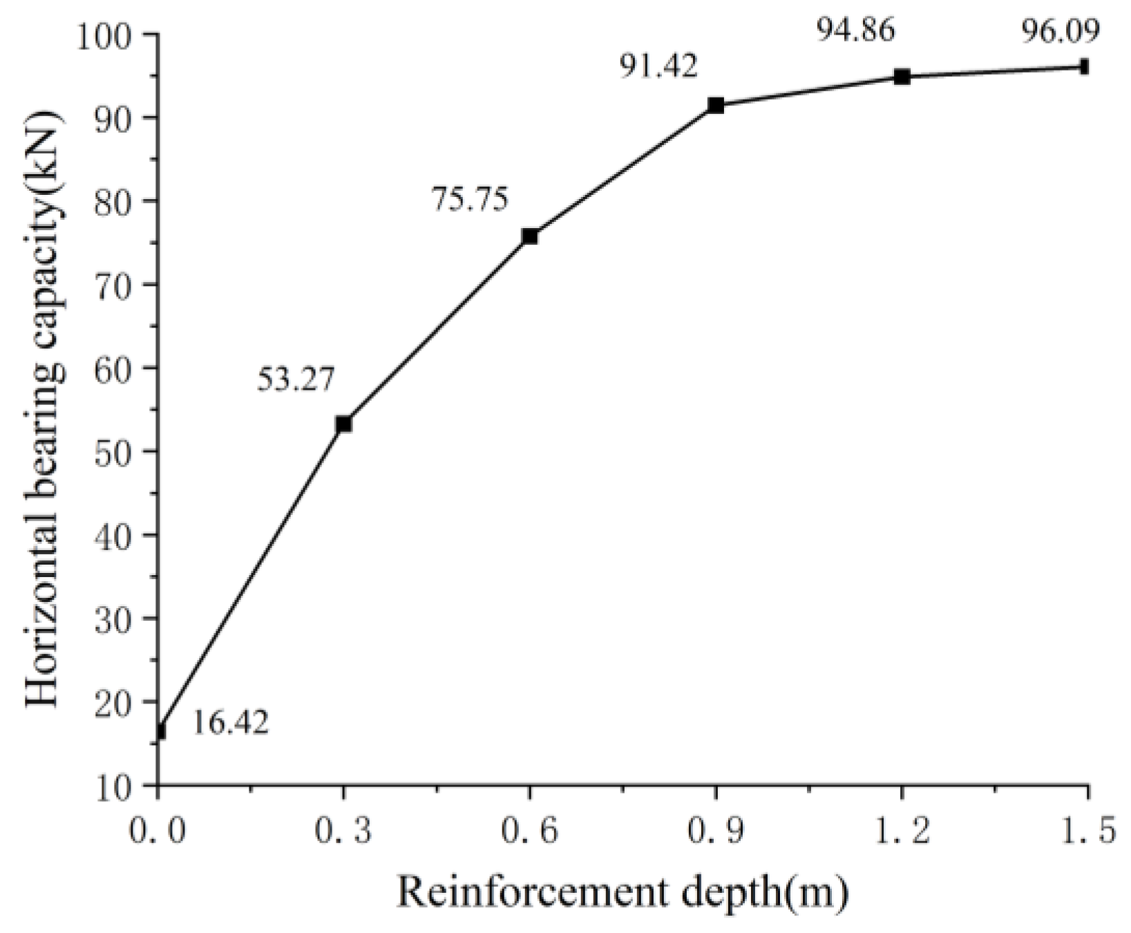
- The bearing capacity of the pile foundation gradually increases with the increase of the reinforcement depth. However, unlike the reinforcement width, the effect of increasing the reinforcement depth on improving the bearing capacity of the pile is gradually weakening, and it can be considered that there is an optimal reinforcement depth of 1.5D. Compared with the unreinforced situation, when the reinforcement depth is 0.5 times, 1.0 times, 1.5 times, 2.0 times, and 2.5 times the pile diameter, the horizontal bearing capacity of the pile body is increased by 224.4%, 361.3%, 456.8%, 477.71%, and 485.2%, respectively.
- (4)
- As the reinforcement depth increases, the increase in bearing capacity does not increase linearly, but gradually decreases. This indicates that simply increasing the reinforcement depth to improve the horizontal bearing capacity of the pile requires a comprehensive consideration of the reinforcement purpose and economy. Blindly carrying out deep soil reinforcement without comprehensive evaluation is not advisable.
- (5)
- Due to space limitations, this article did not consider the combined effect of vertical and horizontal loads in the simulation analysis. Whether this has a significant impact on the relevant conclusions requires further research to confirm. In addition, further specialized research is needed to determine whether the conclusions of this article are applicable to piles with more aspect ratios and soil material properties.
Author Contributions
Funding
Data Availability Statement
Conflicts of Interest
References
- Kellezi, L.; Hansen, P.B.; British Geo Technical Association (BGA). Static and dynamic analysis of an offshore mono-pile windmill foundation. In BGA International Conference on Foundations: Innovations, Observations, Design and Practice, Proceedings of the International Conference Organised by British Geotechnical Association, Dundee, Scotland, 2–5 September 2003; Thomas Telford Publishing: London, UK, 2003; pp. 401–410. [Google Scholar]
- Sun, Y. Test and Numerical Analysis of Horizontal Bearing Characteristics of Super-Large Diameter Single Pile of Offshore Wind Turbine. Ph.D. Thesis, Zhejiang University: Zhejiang, China, 2016. (In Chinese). [Google Scholar]
- Wang, J.; Zhu, Z.H.; Wang, H.Y.; Zhu, Q.H.; Fei, K. Numerical analysis of horizontal bearing capacity of rigid composite pile in clay foundation. J. Railw. Sci. Eng. 2020, 17, 1382–1389. (In Chinese) [Google Scholar]
- Wang, G.; Liao, C.C.; Zhang, L.L.; Lin, J.Q.; Ye, G.L.; Zhang, Z.C. Resistance component analysis and application of large diameter horizontal loaded single pile. J. Civ.Eng. 2024, 57, 72–82. (In Chinese) [Google Scholar]
- Zhang, X.; Yu, D.; Zhu, K.; Zhao, A.; Ren, M. The Horizontal Bearing Characteristics and Microscopic Soil Deformation Mechanism of Pile-Bucket Composite Foundation in Sand. Appl. Sci. 2024, 14, 907. [Google Scholar] [CrossRef]
- Wang, S.; Ma, J.; Wang, C.; Liu, F.; Li, D. An Investigation into the Lateral Bearing Performance of a Single Pile Embedded at a Three-Dimensional Asymmetric Local Scour Site Using the Modified Strain Wedge Model. Appl. Sci. 2024, 14, 3056. [Google Scholar] [CrossRef]
- Ren, M.; Cheng, J.; Zhang, S.; Pang, Y.; Zhu, W. Ultimate Load-Bearing Capacity and Sustainable Performance of Pile Foundations of Yanji Suspension Bridge in Fault Zone Based on Refined Geological Model. Sustainability 2024, 16, 1858. [Google Scholar] [CrossRef]
- Adsero, M.E. Effect of Jet Grouting on the Lateral Resistance of Soil Surrounding Driven-Pile Foundations. Ph.D. Thesis, Brigham Young University, Provo, UT, USA, 2008. (In Chinese). [Google Scholar]
- Rollins, K.M.; Adsero, M.E.; Brown, D.A. Jet grouting to increase lateral resistance of pile group in soft clay. In Contemporary Topics in Ground Modification, Problem Soils, and Geo-Support, Proceedings of the International Foundation Congress and Equipment Expo 2009, Orlando, FL, USA, 15 March 2009; American Society of Civil Engineers: Reston, VA, USA, 2009; pp. 265–272. [Google Scholar] [CrossRef]
- Faro, V.P.; Consoli, N.C.; Schnaid, F.; Thomé, A.; da Silva Lopes, L. Field tests on laterally loaded rigid piles in cement treated soils. J. Geotech. Geoenvironmental Eng. 2015, 141, 06015003. [Google Scholar] [CrossRef]
- Faro, V.P.; Schnaid, F.; Consoli, N.C. Field tests of laterally loaded flexible pile in soil with top cement-treated layers. Proc. Inst. Civ. Eng. Ground Improv. 2018, 171, 174–182. [Google Scholar] [CrossRef]
- He, B. Horizontal Load-Bearing Characteristics of Single Piles and Composite Pile Foundations on Soft Clay Ground; Geo Technical Engineering, Zhejiang University: Zhejiang, China, 2016. (In Chinese) [Google Scholar]
- Taghavi, A.; Muraleetharan, K.K.; Miller, G.A.; Cerato, A.B. Centrifuge modeling of laterally loaded pile groups in improved soft clay. J. Geo Tech. Geoenvironmental Eng. 2016, 142, 04015099. [Google Scholar] [CrossRef]
- Taghavi, A.; Muraleetharan, K.K.; Miller, G.A. Nonlinear seismic behavior of pile groups in cement-improved soft clay. Soil Dyn. Earthq. Eng. 2017, 99, 189–202. [Google Scholar] [CrossRef]
- Wang, A.H.; Zhang, D.W.; Liu, S.Y.; Deng, Y.G. Research on the bearing characteristics of rigid composite tubular piles under horizontal load. J. China Univ. Min. Technol. 2018, 47, 853–861. (In Chinese) [Google Scholar]
- Wang, A.; Zhang, D.; Deng, Y. Lateral response of single piles in cement improved soil: Numerical and theoretical investigation. Comput. Geotech. 2018, 102, 164–178. [Google Scholar] [CrossRef]
- Yu, G.; Gong, W.; Chen, M.; Dai, G.; Liu, Y. Prediction and Analysis of Behaviour of Laterally Loaded Single Piles in Improved Gravel Soil. Int. J. Civ. Eng. 2019, 17, 809–822. [Google Scholar] [CrossRef]
- Zhang, D.W.; Liu, S.C.; Lin, W.F.; Shi, H.B.; Mao, Z.L. Field test of jet grouting piles reinforcing the liquefiable silty soil layer in soft ground. J. Traffic Transp. Eng. 2022, 22, 103–111. (In Chinese) [Google Scholar]
- Rollins, K.M.; Brown, D.A. Design Guidelines for Increasing the Lateral Resistance of Highway-Bridge Pile Foundations by Improving Weak Soils; Transportation Research Board: Washington, DC, USA, 2011. [Google Scholar]
- Jamsawang, P.; Voottipruex, P.; Jongpradist, P.; Bergado, D.T. Parameters affecting the lateral movements of compound deep cement mixing walls by numerical simulations and parametric analyses. Acta Geotech. 2015, 10, 797–812. [Google Scholar] [CrossRef]
- Wang, Z.H. Research on the Horizontal Bearing Characteristics of Large-Diameter Cement-Soil Composite Steel Pipe Piles. Master’s Thesis, Southeast University, Nanjing, China, 2021. (In Chinese). [Google Scholar]
- Cui, Z.Z. Research on the Stability of Borehole Walls and Vertical Bearing Performance of Drilled Cast-in-Place Piles in the Near Front Edge Area of the Yangtze River Delta; China University of Mining and Technology: Xuzhou, China, 2020. (In Chinese) [Google Scholar]
- JGJ 94-2008; Technical Specification for Building Pile Foundations. Ministry of Housing and Urban-Rural Development of the People’s Republic of China: Beijing, China, 2008. (In Chinese)
- JGJ 106-2014; Technical Specification for Testing of Building Foundation Piles. China Architecture Publishing & Media Co., Ltd.: Beijing, China, 2014. (In Chinese)


| Notation | L/m | D/m | Dcem/m | Lcem/m |
|---|---|---|---|---|
| 1 | 3 | 0.6 | 1.2 | 0.3 |
| 2 | 3 | 0.6 | 1.8 | 0.3 |
| 3 | 3 | 0.6 | 2.4 | 0.3 |
| 4 | 3 | 0.6 | 1.8 | 0.6 |
| 5 | 3 | 0.6 | 2.4 | 0.6 |
| Notation | L/m | D/m | Dcem/m | Lcem/m |
|---|---|---|---|---|
| 1 | 3 | 0.6 | 1.8 | 0.3 |
| 2 | 3 | 0.6 | 1.8 | 0.6 |
| 3 | 3 | 0.6 | 2.4 | 0.3 |
| 4 | 3 | 0.6 | 2.4 | 0.6 |
| 5 | 3 | 0.6 | 2.4 | 0.9 |
| 6 | 3 | 0.6 | 2.4 | 1.2 |
| 7 | 3 | 0.6 | 2.4 | 1.5 |
| Soil Mass | C/kPa | φ/° | μ | E/MPa | ρ/(g/cm3) |
|---|---|---|---|---|---|
| Mucky moft soil | 10.9 | 17.2 | 0.35 | 3.77 | 1.75 |
| Silt | 2.5 | 30.8 | 0.3 | 8.71 | 1.93 |
| Cement-stabilized soil | 346 | 38.3 | 0.2 | 130 | 1.76 |
| Pile | / | / | 0.2 | 22,000 | 2.50 |
| Notation | Dcem/D | Lcem/D | Hult/kN | Relative Error/% | |
|---|---|---|---|---|---|
| Experimental Data | Analog Data | ||||
| 1 | 0 | 0 | 80 | 88.26 | 10.32 |
| 2 | 2 | 0.5 | 140 | 150.87 | 7.76 |
| 3 | 3 | 0.5 | 160 | 170.43 | 6.52 |
| 4 | 3 | 1 | 220 | 186.90 | 15.05 |
| 5 | 4 | 1 | 250 | 225.14 | 9.94 |
| 6 | 4 | 1.5 | 250 | 236.17 | 5.53 |
| 7 | 0 | 0 | 80 | 88.26 | 10.32 |
Disclaimer/Publisher’s Note: The statements, opinions and data contained in all publications are solely those of the individual author(s) and contributor(s) and not of MDPI and/or the editor(s). MDPI and/or the editor(s) disclaim responsibility for any injury to people or property resulting from any ideas, methods, instructions or products referred to in the content. |
© 2024 by the authors. Licensee MDPI, Basel, Switzerland. This article is an open access article distributed under the terms and conditions of the Creative Commons Attribution (CC BY) license (https://creativecommons.org/licenses/by/4.0/).
Share and Cite
Bai, G.; Zhang, H.; Wang, B.; Chen, F.; Zhao, J.; Shu, Q. Investigation on the Bearing Performance of a Single Pile in Shallow Reinforced Soft Soil Foundation under Horizontal Load. Buildings 2024, 14, 3166. https://doi.org/10.3390/buildings14103166
Bai G, Zhang H, Wang B, Chen F, Zhao J, Shu Q. Investigation on the Bearing Performance of a Single Pile in Shallow Reinforced Soft Soil Foundation under Horizontal Load. Buildings. 2024; 14(10):3166. https://doi.org/10.3390/buildings14103166
Chicago/Turabian StyleBai, Guanglin, Hong Zhang, Bo Wang, Feng Chen, Jiahao Zhao, and Qianjin Shu. 2024. "Investigation on the Bearing Performance of a Single Pile in Shallow Reinforced Soft Soil Foundation under Horizontal Load" Buildings 14, no. 10: 3166. https://doi.org/10.3390/buildings14103166
APA StyleBai, G., Zhang, H., Wang, B., Chen, F., Zhao, J., & Shu, Q. (2024). Investigation on the Bearing Performance of a Single Pile in Shallow Reinforced Soft Soil Foundation under Horizontal Load. Buildings, 14(10), 3166. https://doi.org/10.3390/buildings14103166