Article

Structural Evaluation on the Floating Production Storage and Offloading Large Flow Gas Processing Module Based on FEM Analysis

1
State Key Laboratory of Ocean Engineering, Shanghai Jiao Tong University, Shanghai 200240, China
2
COSCO SHIPPING (Qidong) Offshore Co., Ltd., Qidong 226259, China
3
COSCO SHIPPING Heavy Industry Co., Ltd., Shanghai 200135, China
4
Key Laboratory of Marine Intelligent Equipment and System, Ministry of Education, Shanghai 200240, China
5
Guangdong Provincial Key Laboratory of Advanced Manufacturing Technology for Marine Energy Facilities, Guangzhou 510006, China
*
Author to whom correspondence should be addressed.
Buildings 2024, 14(10), 3180; https://doi.org/10.3390/buildings14103180 (registering DOI)
Submission received: 12 September 2024 / Revised: 2 October 2024 / Accepted: 4 October 2024 / Published: 6 October 2024
(This article belongs to the Section Building Structures)

Abstract

:
The floating hoisting of floating production storage and offloading (FPSO) production modules introduces substantial challenges due to the propensity for excessive deformation within the typical tubular truss structures during operations. This research proposes a temporary reinforcement scheme, leveraging finite element method simulations under wind, wave, and current loads, to mitigate deformation concerns. Utilizing DNV GeniE software, this study establishes a finite element model, simulating the floating lifting process and conducting a comparative analysis between pre- and post-reinforcement scenarios. The results demonstrate a significant reduction in maximum stress and deformation, substantiating the efficacy of the reinforcement strategy and underscoring the safety and reliability of such operations. The successful execution of this methodology heralds a promising avenue for marine engineering practices, advocating for the optimization of large-scale offshore module installation.

1. Introduction

The diminishing supply of terrestrial petroleum necessitates the exploration of alternative energy sources and new reserves [1]. Oceans, which cover over 70% of the Earth’s surface, are abundant with mineral resources, including oil, natural gas, and hydrates, which remain largely untapped [2]. Offshore oil and gas fields are increasingly becoming the focal point of energy production, possessing the potential to meet the growing global demand for energy.
Floating production storage and offloading units (FPSO) serve as comprehensive offshore bases for the processing of crude oil, encompassing oil–water separation, the treatment of oily wastewater, heating, power generation, the storage and offloading of oil products, the provision of living quarters, and an integrated production command system [3]. FPSO comprises a hull system, production process system (module system), specialized mooring system, and a distinct oil offloading system. The installation of the module system involves module weighing, transportation, lifting, and the connecting of cables and pipelines, with the lifting process demanding stricter technical precision and presenting heightened safety risks [4].
As the marine engineering industry rapidly evolves, offshore modules are becoming increasingly complex and large-scale. The significant increase in module weights complicates the design of lifting schemes and escalates construction difficulty and risk, presenting new challenges to the overall lifting operation of modules [5]. Offshore module lifting is a high-risk engineering task where minor design errors, construction defects, or operational mistakes could lead to severe consequences and substantial losses, thus underlining the urgent need to standardize the design, implementation, and floating crane operations of such projects [6,7,8]. Effective lifting designs not only save costs for shipyards but also reduce project timelines, making research into integrated lifting schemes for large modules indispensable. Extensive research has been conducted on the construction and lifting processes of FPSO, both domestically and internationally. Hwang et al. [9] detailed the entire process from the design to construction of FPSO, highlighting the critical phase of module lifting, which often involves weights exceeding 3000 tons. Yadhav et al. [10] proposed the use of metaheuristic algorithms to optimize the structural lifting scheme of FPSO modules, resulting in cost-effective and optimized support structures. Huang et al. [11] developed an elastic support system that connects the upper modules to the deck, effectively mitigating the concentration of high stresses during transport and lifting, confirmed through multibody finite element numerical simulations. Yang et al. [12] investigated the issue of diagonal tensioning in the lifting process of heavy FPSO topside modules with Eccentric Centers of Gravity, designing a Diagonal Tensioning System that ensures the safe and effective lifting of heavy modules. Han et al. [13] enhanced the safety of lifting operations for FPSO modules by employing expert judgment and Fault Tree Analysis (FTA), with the methodology being validated through a case study of an FPSO module lifting operation in the South China Sea.
Floating manufacturing, a non-traditional construction method, relies on the buoyancy of water to support the structure, segmenting the hull and modules as construction units, and employing a “layered fabrication and stacking” approach to build maritime structures directly on the water’s surface. Our previous study have pioneered the study of employing floating manufacturing to construct the world’s first cylindrical semi-submersible deep-sea floating drilling storage offloading (FDSO) module [14].
Floating lifting, a critical phase within floating manufacturing, has seen widespread application in the installation of FPSO production modules in recent years [15]. This method facilitates the lifting of large modules on the water’s surface, significantly shortening the lifting cycle and enhancing the integrity of the architectural structure, thus greatly improving operational flexibility and efficiency. However, due to the unique nature of its operating environment, floating lifting faces a multitude of technical and safety challenges. Consequently, finite element strength analysis for floating lift adjustments must consider more factors than conventional onshore lifting operations.
Research on the floating lifting of FPSO production modules in marine engineering is limited. To fill this gap, this study proposes a finite element method (FEM) simulation for floating lifting, considering wind, wave, and current loads. FPSO modules are typically categorized by weight into normal heavy (1000–3000 tons) and ultra-heavy (over 3000 tons). This study focuses on an ultra-heavy FPSO module weighing over 3800 tons. The FEM simulation follows DNV standards, using DNV GeniE V6.8 software and real data from the module’s floating lifting process to validate the proposed methods. While stress levels before and after reinforcement remain within allowable limits, the primary goal of the reinforcement is deformation control during lifting. Controlling deformation is essential for ensuring precision in subsequent installations, as minor deviations can cause major assembly issues. The temporary reinforcement strategy significantly improves structural stability and lifting precision, proving effective for large-scale offshore structures. This study offers valuable insights into improving safety and accuracy in floating hoisting operations for ultra-heavy FPSO modules.

2. Methodology

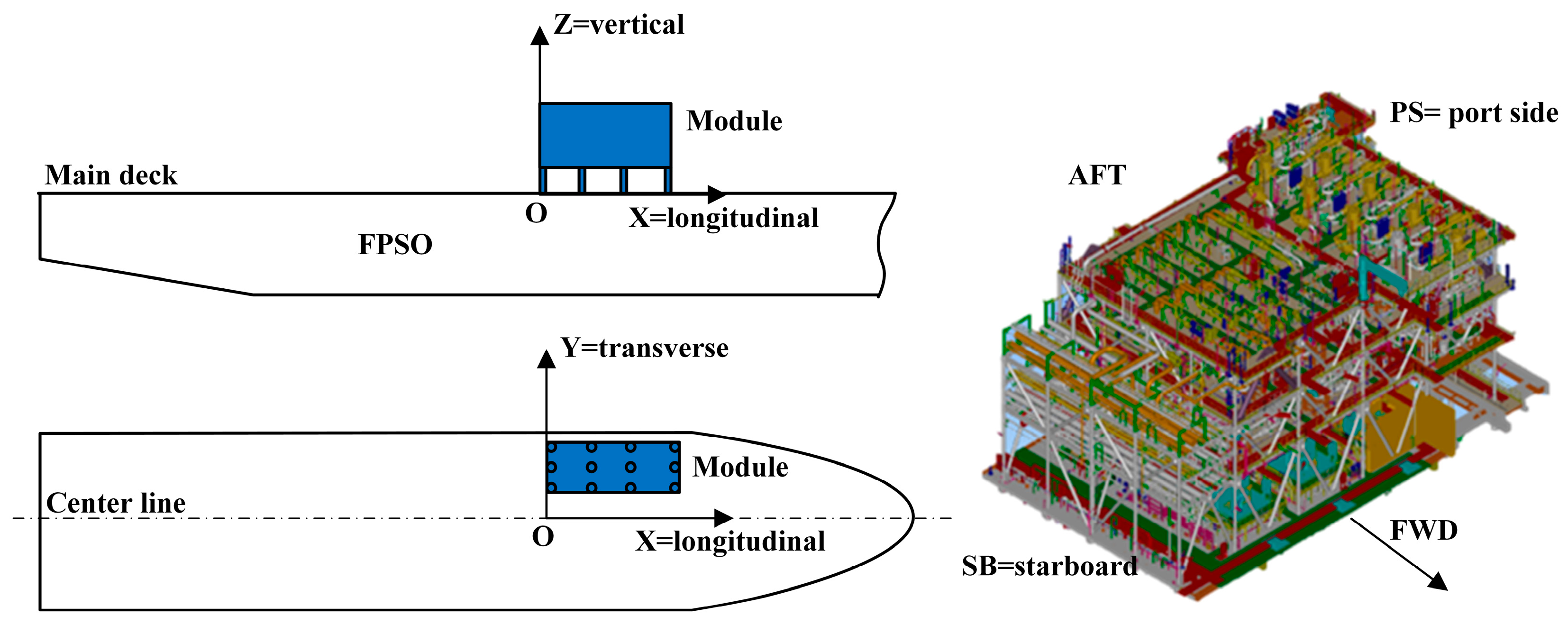
2.1. Simulation Model

This study focuses on a large production module of an FPSO system, measuring 333 m in length, 60 m in width, and 33 m in depth, with a displacement of 460,000 tons, making it the largest FPSO by tonnage and storage capacity globally. The module is primarily responsible for CO2 and LP gas compression. As shown in Figure 1, the study uses a right-handed Cartesian coordinate system (X-Y-Z) with the origin at the mid-deck of the FPSO module. The X-axis points towards the bow, the Y-axis towards the port side, and the Z-axis upwards. This setup ensures alignment between the module’s local coordinate system and the overall FPSO structure, facilitating accurate load and response calculations during lifting and installation. The module’s dimensions are 29.67 m × 46.56 m × 29.69 m, with a weight of 3876.79 tons. The structure is built from high-strength structural steel with the following material properties: 20 mm plate thickness, a yield strength of 450 MPa for plates, 384 MPa for beams, and 355 MPa for tubular elements. Additional properties include a density of 7850 kg/m3, an elastic modulus of 206 GPa, and a Poisson’s ratio of 0.3, as summarized in Table 1. These specifications ensure the module’s structural integrity during the floating lifting process.
The FEM model of the module was established using the finite element analysis software DNV GeniE. DNV GeniE is specifically designed for the structural analysis of offshore platforms and floating structures, making it ideal for this study. The main structure was modeled using plate and shell elements for the pancake structure, including the steel floor plates, while beam elements were used for the support structure, composed of tubular columns and braces. In DNV GeniE, only the plate and shell components require mesh division, while the beam elements are modeled directly, and the software automatically calculates beam stress and deformation results. The mesh size for the plate and shell elements was set to 1 m, resulting in a total of 13,077 elements and 8586 nodes. The model also incorporates loads and masses resulting from equipment, piping, electrical instrumentation, and mechanical handling beams. Figure 2a presents the structural model, while Figure 2b shows the mesh model used to conduct the finite element analysis for the floating lifting of the module.

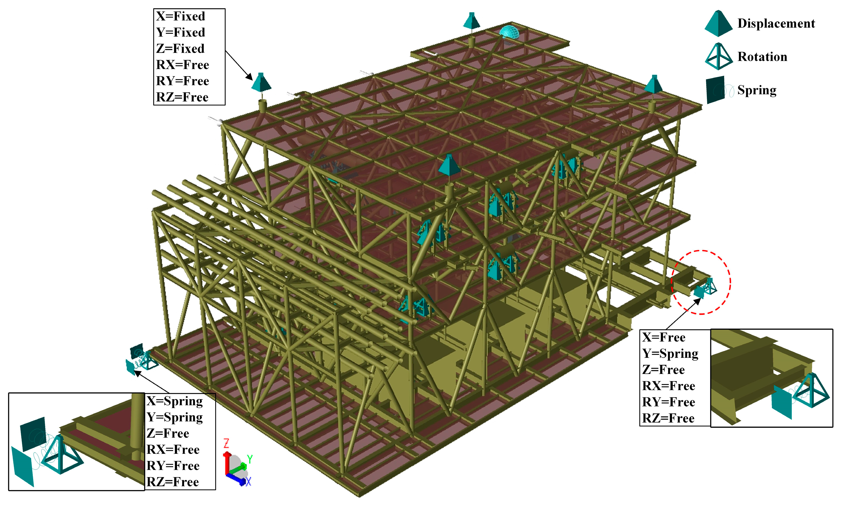
2.2. Boundary Conditions

For the lifting calculation model that includes a sling model, the sole boundary condition applied is at the upper end of the slings, which are allowed to rotate due to the connection being rotatable. This setup involves fixing the translational degrees of freedom while allowing rotational freedom at the node locations of the sling eyes. This type of support simulates a fully constrained condition, allowing no displacement but permitting rotation. It typically represents the connection state between the lifting points and the lifting equipment, ensuring that there is no translational movement at the nodes during lifting while allowing free rotation in order to accommodate dynamic changes during the lifting process.
However, if the center of gravity of the model is slightly unbalanced, the model may rotate indefinitely during calculations, leading to insufficient constraint and causing the simulation to fail. To ensure the stability of the module during analysis, this study employs virtual spring supports at the base of the module’s support columns. These supports limit rotational movement and are used to simulate the dynamic response characteristics of the structure under the action of wind, waves, and currents in actual operating conditions. Figure 3 below illustrates this setup.

2.3. Load Design

In the finite element analysis of floating lifting for an FPSO production module, determining the design load is a crucial task. The loads must account for the module’s own weight and structural characteristics, as well as the environmental dynamic loads from wind, waves, and currents under operational sea conditions. This study, guided by DNV standards, focuses on these primary loads while excluding factors such as earthquake loads, thermal loads, and operational loads, as they are either mitigated through engineering planning or not relevant under controlled lifting conditions. The load model designed in this study reflects the actual operational specifications, ensuring accuracy and relevance for the floating lifting process.
Initially, the study establishes the static loads that the module experiences under normal lifting conditions, including the total weight of the module. Based on this, additional loads are superimposed due to the potential eccentricity, rigging deviations, and horizontal accelerations encountered during the lifting process, as demonstrated by the following formula:
F e c c e n t r i c = m e g
F r i g g i n g   = m d r i g g i n g   g
F h o r i z o n t a l   = m a h o r i z o n t a l  
where Feccentric represents the force caused by eccentricity [N], m represents the total weight of the structure and components as calculated above [kg], e represents the distance of eccentricity [m], g is the acceleration due to gravity [9.81 m/s2], Frigging represents the force caused by rigging deviation [N], drigging represents the distance of the rigging deviation [m], Fhorizontal represents the force caused by horizontal acceleration [N], and ahorizontal represents the horizontal acceleration [m/s2].
In the actual lifting process, it is necessary to consider all possible load scenarios and apply appropriate safety factors to ensure the safety of the operation. Therefore, the design load is a linear combination of all static and additional loads, multiplied by the corresponding safety factors. According to DNV standards, finite element modeling calculations are carried out for the FPSO module structure, divided into two stages, before lifting and during the lifting process, to verify stress and deformation. Before lifting, the module is placed on the platform’s cradle, and the inertial load is simply the gravitational acceleration; during lifting, considering the impact on the structure at the moment of lifting, the inertial load is taken as 1.2 times the original gravitational acceleration to approximate the simulation [4].
Additionally, to simulate the impact of wind, current, and wave loads on the lifting process, this study provides detailed descriptions of each. Wind loads are calculated based on predetermined wind speeds and corresponding meteorological data, taking into account the wind pressure and wind speed gradients in different directions. Current and wave loads are calculated based on ocean current fields and wave spectrum data, reflecting the dynamic effects of sea currents and waves on the FPSO module and its lifting process.
The stability of the floating lifting operation under complex environmental loads is analyzed, focusing on the overall environmental loads of the floating lifting system, which include wind, current, and wave loads—each varying with sea conditions without considering their coupling effects. According to real-time monitoring, the operation area is dominated by the southwest monsoon in summer and the northeast monsoon in winter [16]. The average environmental parameters for the area during summer are as shown in Table 2.
(1) Wind Load:
Wind loads are considered as a uniformly distributed velocity field [17]. The pressure exerted by the wind on the structural surface, denoted as Pwind [N/m2], is calculated using the traditional drag force formula. The formula for calculating wind pressure is given by
P wind = 1 2 ρ air C d V wind 2
where ρair represents the mass density of air 1.22 kg/m3 for standard temperature and pressure. Cd represents the drag coefficient. Vwind represents the wind speed [m/s].
(2) Current Load:
Considering the current load velocity field as uniformly distributed [18], the current load can be expressed as follows:
F c x = 1 2 ρ c v c 2 C c x φ c T L
F cy = 1 2 ρ c v c 2 C cy φ c T L
M c φ = 1 2 ρ c v c 2 C cz φ c T L 2
where Fcx, Fcy, and M represent the contributions of the current load to the floating crane ship in the surge, sway, and yaw directions, respectively. ρc is the density of seawater 1025 kg/m3. vc is the relative velocity of the sea current [m/s]. Ccx(φc), Ccy(φc), and Ccz(φc) are the coefficients of the current load affecting the floating crane ship in the surge, sway, and yaw directions, respectively. φc is the angle of incidence of the sea current relative to the positive x-axis of the floating crane ship. T is the average draft of the floating crane ship [m].
(3) Wave load:
Wave load is calculated using wave spectrum data, which characterizes the distribution of wave energy across frequencies and directions [19]. The Morrison equation is commonly employed to calculate the wave forces on structural elements [20]. This equation is given by the following:
F wave = 1 2 ρ water C d A sub V ˙ wave 2 + ρ water C m V sub η . .
where Vwave represents the wave particle velocity. Cm represents the added mass coefficient. Vsub represents the submerged volume of the structure. η represents the particle acceleration due to waves.
When designing the load scheme, the stability of the FPSO module during lifting must also be considered. To ensure stability and safety throughout the lifting process, careful selection and calculation of the floating body’s buoyancy and the positions of the lifting points are essential. The entire production module is lifted through lifting holes by hooks attached to slings, with only vertical gravitational acceleration remaining in a natural state during the lifting operation. Based on the weight distribution, the weights of various components and any related equipment are applied to each deck. According to standards, factors such as shifts in the center of gravity, rigging deviations, and horizontal accelerations are considered. A safety factor for gravity is set at 1.2, and a horizontal inclination angle of 10° (approximately 0.18 g) is maintained.
During lifting, dynamic loads are generated on the crane vessel and cargo ship due to wave action. These loads are typically accommodated by applying a Dynamic Amplification Factor (DAF) to the static loads on the hooks and slings. Currently, a typical DAF value used in semi-submersible crane vessels (SSCV) is about 1.10. This factor is applied in addition to any quasi-static changes related to load transfer through the hooks and slings.

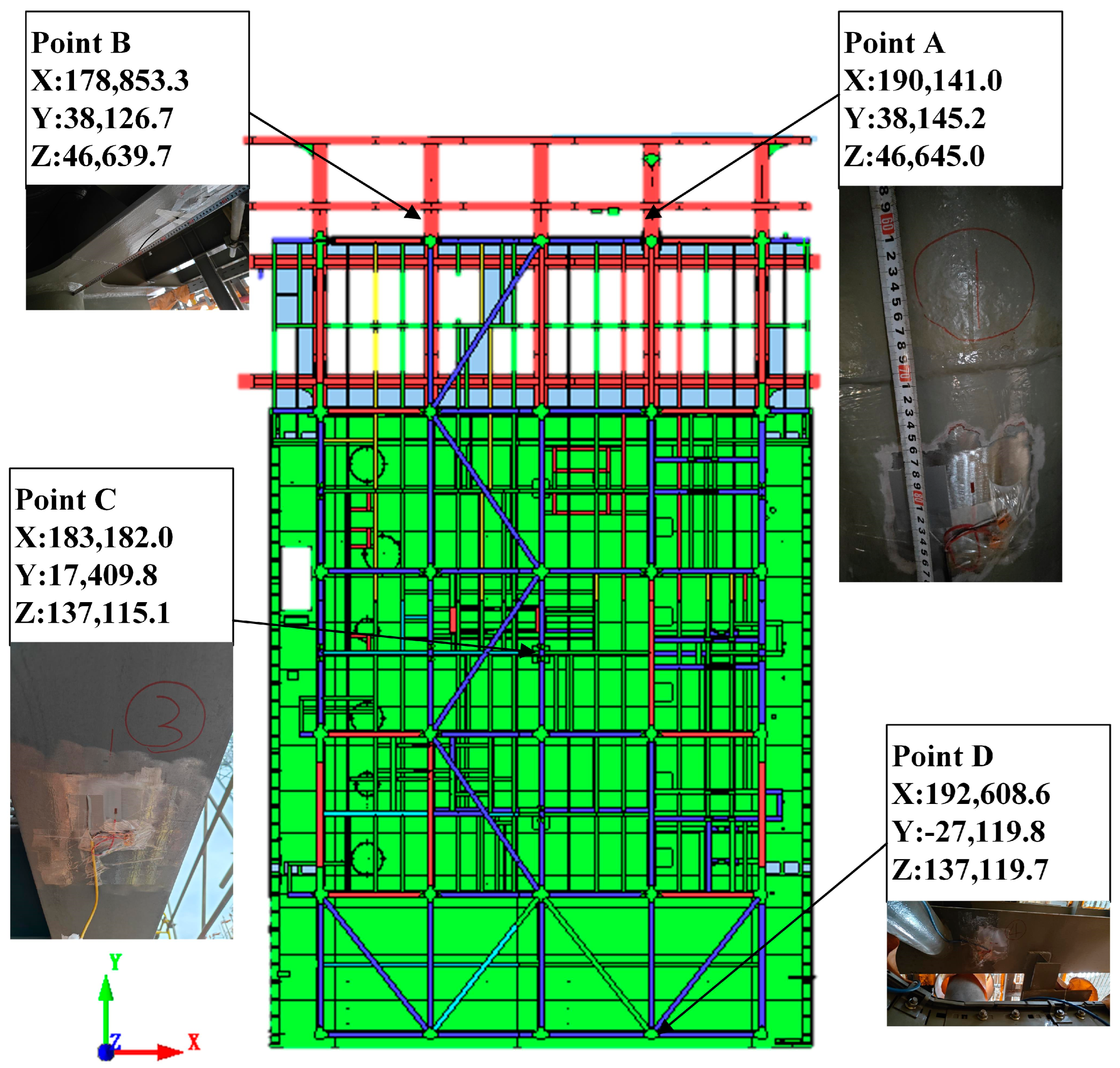
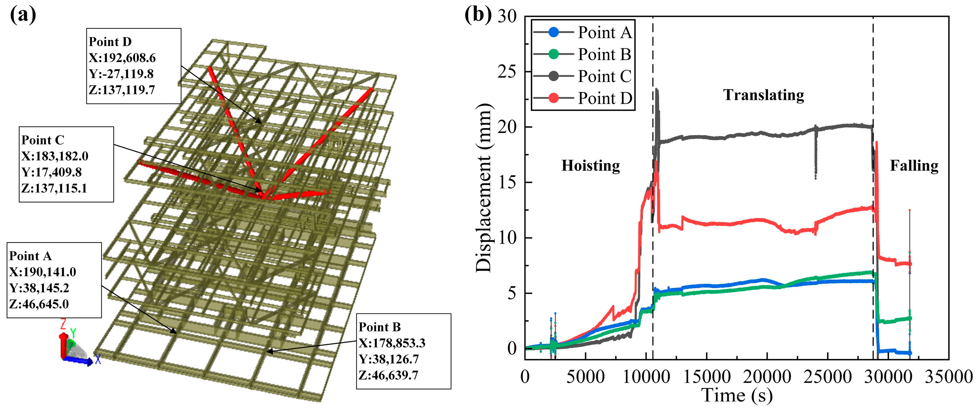
2.4. Lifting Procedure and Monitoring

During the module lifting process, the Xinzhenfu 7500 T crane ship was used, with a main hook capacity of 4 × 1250 T and an auxiliary hook capacity of 600 T. Spreaders were employed to ensure the lifting forces that remained within the vertical plane and to minimize lifting interferences by adjusting the path of the steel wire ropes. For large offshore modules, frame-style spreaders were used, designed to optimize stress distribution and reduce the angle between the wire ropes and the lifting lugs [21]. The self-designed frame-style spreader used in this study is shown in Figure 4.
To monitor the stress and strain on the module during the floating lifting process, this study has setup four monitoring points as illustrated in Figure 5, based on the results from the finite element analysis. KYOWA Electronic Instruments Co., Ltd. manufactured KFGS-5-120-C1-11 L1M2R uniaxial strain gauges which are used as front-end sensors, with CC-33A room temperature curing instant adhesive used as the bonding agent, and Avic Electronic Measurement Instrument Co., Ltd. produced G-704 single-component room temperature vulcanizing silicone rubber, used as the protective coating. The stress and strain data acquisition system employed is the DH3823 from Jiangsu Donghua Testing Technology Co., Ltd.
Prior to attaching the strain gauges, the area for measurement is polished and cleaned. A multimeter is used to measure the resistance of the strain gauge to ensure that the resistance value matches the nominal value indicated on the packaging. After the calibration and setup of the strain gauges, the exposed surfaces are covered with the sealing glue (G-704) to protect them. This meticulous preparation and protection help ensure the accuracy and reliability of the data collected during the lifting operations.

3. Results and Discussion

In the finite element analysis of the floating lifting operation for an FPSO production module, Figure 6 provides detailed insight into the stress and vertical displacement distribution under static loading conditions [22]. The analysis focuses on beam stress, as the beams and structural members primarily bear the axial forces during the lifting process. Figure 6a shows the overall beam stress distribution, with a maximum stress of 101.89 MPa, concentrated around the lifting lugs and the horizontal I-beams connected to the tubular structures, which directly bear the localized high loads introduced by the slings. Figure 6b illustrates the vertical displacement distribution for the entire structure, with a maximum displacement of 26.53 mm, primarily occurring in the vertical direction, as expected during the lifting operation. The most significant displacement is near the lifting lugs, indicating critical areas that require careful monitoring. Figure 6c further highlights the stress distribution in the tubular sections, with stress concentrated at the joints connecting the tubular members to the I-beams, indicating that these areas experience high axial forces. Lastly, Figure 6d presents the vertical displacement of the horizontal I-beams, where deformation is most pronounced near the edges, particularly where the lifting slings are attached, underscoring the importance of ensuring adequate stiffness in these regions.
From a structural mechanics perspective, stress concentration typically arises from localized high loads, sudden changes in geometry, or variations in material properties. In this case, the triangular support tubes beneath the lifting points are in the stress concentration zone because these positions are integral to the path through which lifting forces are transmitted. They not only carry the module’s own weight but also endure additional loads due to the dynamic interactions between the lifting points and the lifting equipment during the operation [23].
The most significant deformation occurs in the middle area of the module’s second layer, indicative of relatively low structural rigidity in this region. The lack of rigidity results from insufficient internal support caused by the layout of production and processing equipment, coupled with a shortage of adequate longitudinal and transverse components to distribute and bear the loads during lifting. The vertical downward gravity and upward pulling forces during lifting subject the central area to significant vertical bending moments [24]. Coupled with the module’s extensive span and minimal rigidity, this leads to substantial global deformation in the central area. In extreme cases, this could result in plastic deformation or even tearing, compromising the equipment supports and affecting the integrity of the outfitting. Thus, subsequent structural reinforcement measures will need to focus on these areas, potentially through adjusting the layout of internal components or adding additional support structures to enhance load-bearing capacity and limit deformation.
Figure 7 shows the stress and deformation contour maps of the module during floating hoisting, considering the wind, wave, and current loads. The results differ from static hoisting due to the additional accelerations from wind and wave action. The maximum stress recorded is 103.61 MPa, with a maximum deformation of 29.14 mm. The FEA results indicate that stress concentrations typically occur at the nodes and connections of the truss framework, where structural elements intersect and load paths converge. These areas experience high stress due to the complex force distribution and local loading conditions. The nodes where lifting slings attach endure significant stress, as they serve as primary load transfer points. The maximum deflections are observed at the mid-span of larger truss sections, caused by bending moments due to their geometric position and the span between supports. These areas are particularly susceptible to deformation under dynamic loads from waves and wind during hoisting.
In light of the typical tubular truss structure of FPSO production modules and the excessive deformation encountered during floating state hoisting, this study introduces a temporary reinforcement scheme specifically designed to control stress and deformation. For sections experiencing significant deflections, temporary support beams or bracing trusses are implemented to increase the anti-bending stiffness of the truss members. These reinforcements are designed to resist bending moments and effectively limit mid-span deflection to acceptable levels. The reinforcement configuration shown in Figure 8, with four tubular reinforcements extending from the primary lifting points to the mid-span of the second-tier truss, plays a critical role in optimizing the distribution of hoisting forces [25]. This setup minimizes bending and ensures that stresses are more evenly spread across the structure, rather than being concentrated at specific points.
Moreover, the design of the reinforcement takes into account practicality and cost-efficiency by utilizing surplus tubular materials from the shipyard’s construction activities. This economical approach not only prevents structural interference during operations, but also effectively disperses the stress at lifting points during hoisting, reducing localized stress concentration and controlling deflection. The reinforcement ensures the overall structural integrity of the module by distributing the load more evenly across a larger area, thereby managing both stress and deformation during the floating hoisting process.
Subsequently, a detailed finite element analysis was conducted on the floating hoist post-reinforcement. The results, as shown in Table 3, indicate that the temporary reinforcement significantly reduced the maximum beam stress during hoisting from 103.61 MPa to 84.52 MPa and that the maximum Z-direction deformation decreased from 29.14 mm to 19.36 mm. These results validate the effectiveness of the reinforcement strategy in mitigating stress and deformation, ensuring safer lifting conditions. The stress and deformation contour maps presented in Figure 9 further illustrate these improvements.
In summary, the implemented temporary reinforcement measures markedly enhanced the structural performance during the hoisting operation, ensuring the safety and reliability of the project. This approach not only improved the structural stability during critical lifting operations, but also aligned with sustainable practices by utilizing surplus materials, thereby reducing waste. The post-reinforcement analysis confirmed the efficacy of these interventions, offering a robust framework for safeguarding the safety and integrity of heavy marine structures in complex lifting scenarios. This study provides valuable insights into addressing the practical challenges of floating hoisting for large marine structures, with potential applications extending beyond shipyards to other sectors requiring similar heavy lifting capabilities.
Figure 10 depicts the full-process deformation monitoring of the production module during the actual floating hoisting, focusing on four measured points. During the lifting phase, the displacement of all measurement points shows a stable increasing trend, reflecting the structural response as the module is lifted off the support structure. Notably, point C exhibits the most significant displacement increase, reaching up to approximately 22 mm. This point is located in the middle area of the module’s second layer. The internal support in this area is insufficient due to the layout of production and processing equipment, leading to significant vertical bending moments as a result of the downward gravitational force and upward tensile force experienced during the lifting process. Additionally, the large span and relatively low stiffness of the module contribute to considerable global deformation in the central area. After temporary reinforcement, effective deformation reduction was achieved through the more uniform redistribution of stresses. During the translation phase, the displacement of the four measurement points remained relatively stable, with minor fluctuations around 5 mm. This behavior indicates that structural deformation remains constant or is adjusted slightly due to changes in the module’s orientation as it is horizontally moved to the destination. In the lowering phase, all four measurement points show a sudden decrease in displacement, corresponding to the module being placed onto the new support foundation.
In this study, in addition to finite element analysis (FEM), other commonly used methods for stress and deformation analysis of floating lifting modules include analytical methods, empirical approaches, and scaled model experiments. Analytical methods are suitable for preliminary analysis of simple structures but cannot accurately handle complex dynamic loads. Empirical approaches, while fast, rely on historical data and lack precision. Scaled model experiments, though providing physical insights, are costly and limited in replicating real-world conditions. In contrast, FEM offers significant advantages, such as accurately simulating stress and deformation under complex geometries and dynamic load conditions, handling non-linear problems, and allowing mesh refinement in critical areas for improved accuracy. Furthermore, FEM is cost-effective and enables iterative design optimization. Thus, FEM stands out as the superior method for analyzing stress and deformation in floating lifting modules due to its precision, versatility, and efficiency in complex marine engineering applications.

4. Conclusions

This study established a finite element model for the floating state hoisting of an FPSO production module using DNV GeniE software, focusing on the calculation of structural stress and displacement during the lifting process. Temporary structural reinforcement was introduced to enhance stability, and the following conclusions were drawn:
(1)
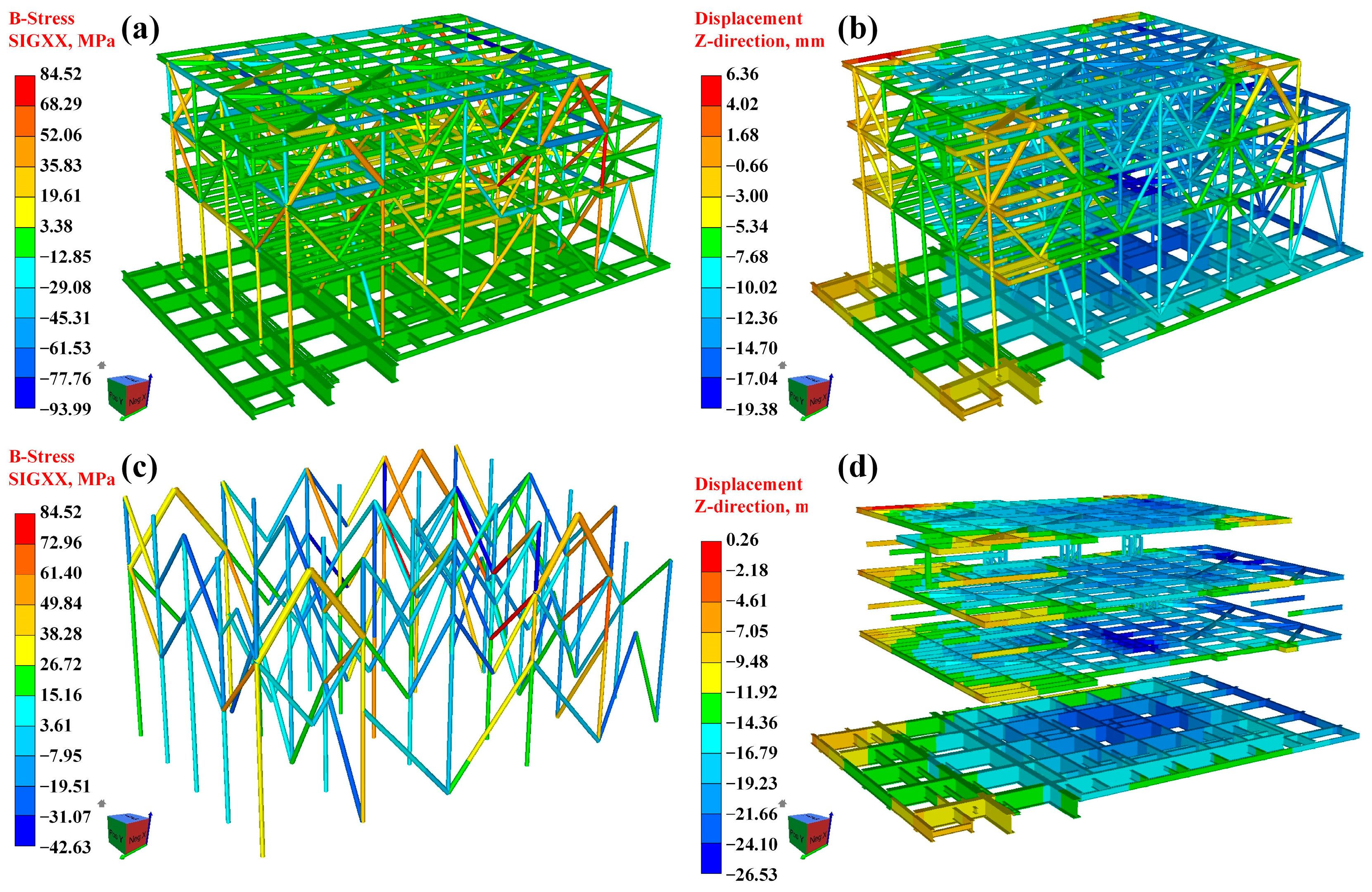
The finite element analysis (FEA) executed in DNV GeniE software demonstrated a significant improvement in the structural integrity of the FPSO production module following the implementation of temporary reinforcement during the floating lifting process.
(2)
The maximum stress in the module was reduced from pre-reinforcement levels to 84.52 MPa, and the maximum deformation was similarly reduced to 19.36 mm. These results validate the effectiveness of the temporary reinforcement in controlling both stress and deformation, ensuring safe lifting conditions.
(3)
The strategically placed temporary support effectively controlled excessive deformation, confirming the robustness of this reinforcement strategy for heavy lifting operations in marine environments.
This study offers valuable insights into the design and implementation of heavy lifting procedures, with potential applications beyond shipyards, extending to other sectors requiring similar lifting capabilities. Furthermore, by utilizing surplus construction materials for the reinforcement, the study aligns with sustainable practices. The findings underscore the importance of precise planning and structural interventions to ensure the safety and integrity of marine structures during complex lifting operations.

Author Contributions

Supervision, Writing—review & editing, M.Q.; Investigation, Y.H.; Methodology, Y.L.; Project administration, Validation, Z.W.; Software, M.L.; Writing—original draft, Z.Z.; Data curation, Resources, Y.Z.; Conceptualization, C.L.. All authors have read and agreed to the published version of the manuscript.

Funding

This work is financially supported by the Marine Economy Development of Guangdong Province (six Marine industries) special fund project (GDNRC[2023]28).

Data Availability Statement

Dataset available on request from the authors.

Conflicts of Interest

Author Ming Qiu and Zhengang Wang were employed by the company COSCO SHIPPING (Qidong) Offshore Co., Ltd., author Yibin Lyn was employed by the company COSCO SHIPPING Heavy Industry Co., Ltd. The remaining authors declare that the research was conducted in the absence of any commercial or financial relationships that could be construed as a potential conflict of interest.

References

  1. Armaroli, N.; Balzani, V. The Future of Energy Supply: Challenges and Opportunities. Angew. Chem. Int. Ed. 2007, 46, 52–66. [Google Scholar] [CrossRef] [PubMed]
  2. Collett, T.S. Energy resource potential of natural gas hydrates. AAPG Bull. 2002, 86, 1971–1992. [Google Scholar]
  3. Meng, H.; Kloul, L.; Rauzy, A. Production availability analysis of Floating Production Storage and Offloading (FPSO) systems. Appl. Ocean Res. 2018, 74, 117–126. [Google Scholar] [CrossRef]
  4. Rho, Y.-H.; Kim, K.; Jo, C.-H.; Kim, D.-Y. Static and dynamic mooring analysis–stability of floating production storage and offloading (FPSO) risers for extreme environmental conditions. Int. J. Nav. Archit. Ocean Eng. 2013, 5, 179–187. [Google Scholar]
  5. Picard, L.; Blanchet, P.; Bégin-Drolet, A. On-site handling: Automated connecting device for modular construction used as lifting apparatus. Structures 2024, 63, 106318. [Google Scholar] [CrossRef]
  6. Momeni, B. In-Place and Lift Analysis of an Offshore Module: Comparative Study. Master’s Thesis, University of Stavanger, Stavanger, Norway, 2015. [Google Scholar]
  7. Lundqvist, A. Structural Analysis for Heavy Lift Removal of Offshore Module. Master’s Thesis, University of Stavanger, Stavanger, Norway, 2009. [Google Scholar]
  8. Ali, I. Structural Modelling of Offshore Module for Loadout, Transportation and Installation. Master’s Thesis, University of Stavanger, Stavanger, Norway, 2014. [Google Scholar]
  9. Hwang, J.-K.; Roh, M.-I.; Lee, K.-Y. Detailed design and construction of the hull of a floating, production, storage and off-loading (FPSO) unit. Ships Offshore Struct. 2010, 5, 93–104. [Google Scholar] [CrossRef]
  10. Yadhav, A.; Kulkarni, M. Optimal design of FPSO topside module for in-place, lift and weighing conditions utilizing meta-heuristic optimization algorithms. Asian J. Civ. Eng. 2023, 24, 3055–3070. [Google Scholar] [CrossRef]
  11. Huang, Y.; He, Y.; Liu, Y.; Qiu, M.; Li, M.; Luo, Z. Application and analysis of elastomeric supporting style for topside modules of a spread mooring FPSO. Ocean Eng. 2022, 261, 112183. [Google Scholar] [CrossRef]
  12. Yang, Y.T.; Kwon, J.S. Development of Diagonal Tensioning System For Lifting FPSO Topside Module With Eccentric Center of Gravity. In Proceedings of the ISOPE International Ocean and Polar Engineering Conference, Rhodes, Greece, 16–21 June 2004; p. ISOPE-I. [Google Scholar]
  13. Han, F.; Yu, J.; Chen, H.; Wu, Z.; Lei, Y.; Liu, J. Risk analysis method of FPSO module hoisting and its application. China Saf. Sci. J. 2019, 29, 123. [Google Scholar]
  14. Wang, F.; Zhang, Y.; Wang, Y.; Xu, Z.; Zhang, Z.; Ni, T.; Zhuang, J.; Tu, Y.; Qian, B. Floating non-traditional manufacture of floating drilling storage and offloading units—Study on modeling and optimization method for the underwater rotating technology. Mar. Struct. 2013, 31, 15–23. [Google Scholar] [CrossRef]
  15. Wen, Y.; Chen, G.; Wang, Y.; Zhao, D.; Lian, Z.; Sun, Z. The Study on Finite Element Strength Analysis for FPSO Accommodation Lifting. In Proceedings of the ISOPE International Ocean and Polar Engineering Conference, Honolulu, HI, USA, 16−21 June 2019. [Google Scholar]
  16. Qian, W.; Lee, D.-K. Seasonal march of Asian summer monsoon. Int. J. Climatol. 2000, 20, 1371–1386. [Google Scholar] [CrossRef]
  17. Davenport, A.G. The application of statistical concepts to the wind loading of structures. Proc. Inst. Civ. Eng. 1961, 19, 449–472. [Google Scholar] [CrossRef]
  18. Yahagi, K.; Takagi, K. Moment loads acting on a blade of an ocean current turbine in shear flow. Ocean Eng. 2019, 172, 446–455. [Google Scholar] [CrossRef]
  19. Tannuri, E.A.; Sparano, J.V.; Simos, A.N.; Da Cruz, J.J. Estimating directional wave spectrum based on stationary ship motion measurements. Appl. Ocean Res. 2003, 25, 243–261. [Google Scholar] [CrossRef]
  20. Sarpkaya, T. Morison’s Equation and the Wave Forces on Offshore Structures; Naval Civil Engineering Laboratory: Carmel, CA, USA, 1981. [Google Scholar]
  21. Cosson, D.; Rowe, M.; Koolhof, W. Wheatstone subsea installation-Challenges associated with large numbers of Subsea heavy lifts and Spools Offshore Australia. In Proceedings of the Offshore Technology Conference Asia, Kuala Lumpur, Malaysia, 20–23 March 2018; OTC: Colombo, Sri Lanka, 2018; p. D031S018R003. [Google Scholar] [CrossRef]
  22. Park, K.-P.; Cha, J.-H.; Lee, K.-Y. Dynamic factor analysis considering elastic boom effects in heavy lifting operations. Ocean Eng. 2011, 38, 1100–1113. [Google Scholar] [CrossRef]
  23. Zhao, T.-F.; Zhang, Q.-Y.; Chu, G. Truss-type maintenance devices and corresponding pipeline lifting control strategies. Pet. Sci. 2021, 18, 939–950. [Google Scholar] [CrossRef]
  24. Tian, L.; Hao, J.; Wei, J.; Zheng, J. Integral lifting simulation of long-span spatial steel structures during construction. Autom. Constr. 2016, 70, 156–166. [Google Scholar] [CrossRef]
  25. Li, G.; Mo, T.; Xu, N.; Zhang, W.; Lu, H.; Deng, D. Improvement of overall lifting construction technology of large span steel structure hangar. In Proceedings of the 2nd International Conference on Internet of Things and Smart City (IoTSC 2022), Xiamen, China, 18–20 February 2022; SPIE: Bellingham, WA, USA, 2022; Volume 12249, pp. 923–928. [Google Scholar]
Figure 1. Local coordinate system used in module calculation.
Buildings 14 03180 g001
Figure 2. The FEM model of the lifting module. (a) Structural model. (b) Mesh model.
Buildings 14 03180 g002
Figure 3. The boundary conditions of FEM model.
Buildings 14 03180 g003
Figure 4. The site where the module is lifted by a frame-type lifting device.
Buildings 14 03180 g004
Figure 5. The four stress–strain monitoring points.
Buildings 14 03180 g005
Figure 6. The results of the static finite element analysis for the lifting. (a) Beam stress distribution for the overall structure; (b) Z-Displacement distribution for the overall structure; (c) Beam stress distribution for the tubular; (d) Z-Displacement distribution for the beam.
Buildings 14 03180 g006
Figure 7. The results of the finite element analysis for the floating lifting. (a) Beam stress distribution for the overall structure; (b) Z-Displacement distribution for the overall structure; (c) Beam stress distribution for the tubular; (d) Z-Displacement distribution for the beam.
Buildings 14 03180 g007
Figure 8. The temporary reinforcement plan for the module.
Buildings 14 03180 g008
Figure 9. The results of the finite element analysis for the floating lifting by the temporary reinforcement plan. (a) Beam stress distribution for the overall structure; (b) Z-Displacement distribution for the overall structure; (c) Beam stress distribution for the tubular; (d) Z-Displacement distribution for the beam.
Buildings 14 03180 g009
Figure 10. The results of the displacement monitoring during the actual floating state hoisting process. (a) The location of the measuring point. (b) Real-time monitoring of deformation results.
Buildings 14 03180 g010
Table 1. Material properties of the structure.
TypeDensity (kg/m3)Elastic Modulus (GPa)Poisson’s RatioYield Strength (MPa)
Plate78502060.3450
Beam78502060.3384
Tubular78502060.3355
Table 2. Average environmental parameters of the operating area.
ParametersValueIncident Angle/(°)Value
Wind speed/(m·s−1)8.0Wind60
Current speed/(m·s−1)0.3Current225
Significant wave height/(m)1.5Wave104
Swell height/(m)0.9Swell172
Table 3. Comparison of maximum stress and deformation of lifting.
Maximum Beam StressMaximum Z-Deformation
Static lifting101.89 MPa26.53 mm
Floating lifting103.61 MPa29.14 mm
Floating lifting (with temporary reinforcement)84.52 MPa19.36 mm
Disclaimer/Publisher’s Note: The statements, opinions and data contained in all publications are solely those of the individual author(s) and contributor(s) and not of MDPI and/or the editor(s). MDPI and/or the editor(s) disclaim responsibility for any injury to people or property resulting from any ideas, methods, instructions or products referred to in the content.

