
Investigation of a Novel Thermochemical Reactor for Medium- and Low-Temperature Heating Applications in Buildings


Abstract
:1. Introduction
1.1. The Need to Use Sustainable Measures in Medium- and Low-Temperature Heating
1.2. Review of Recent Thermochemical Reactor Developments for Medium- and Low-Temperature Heating
1.3. Innovations and Contributions of This Study
- (1)
- In-depth investigations of an innovative triangular honeycomb reactor;
- (2)
- Extensive parametric analysis based on reactor configuration studies.
- (1)
- In-depth studies on a novel triangular honeycomb reactor, with a 140% improvement in air–reactant contact area compared to conventional designs, enhancing energy storage and efficiency;
- (2)
- A detailed critical parametric performance study, including comprehensive analysis of reactor parameters, including energy density, pressure drop, air distribution, and round-trip efficiency, providing new insights into optimal reactor configurations for thermochemical energy storage;
- (3)
- Optimized energy control, offering valuable data to improve flexible charging and discharging controls, ensuring effective energy storage and release;
- (4)
- Contribution to low-carbon heating, including the evaluation of the reactor’s feasibility for residential heating applications in cold regions and calculation of the required reactor volume for real-world heating demands.
2. The Energy Storage Process and Descriptions of the Novel Honeycomb Reactor
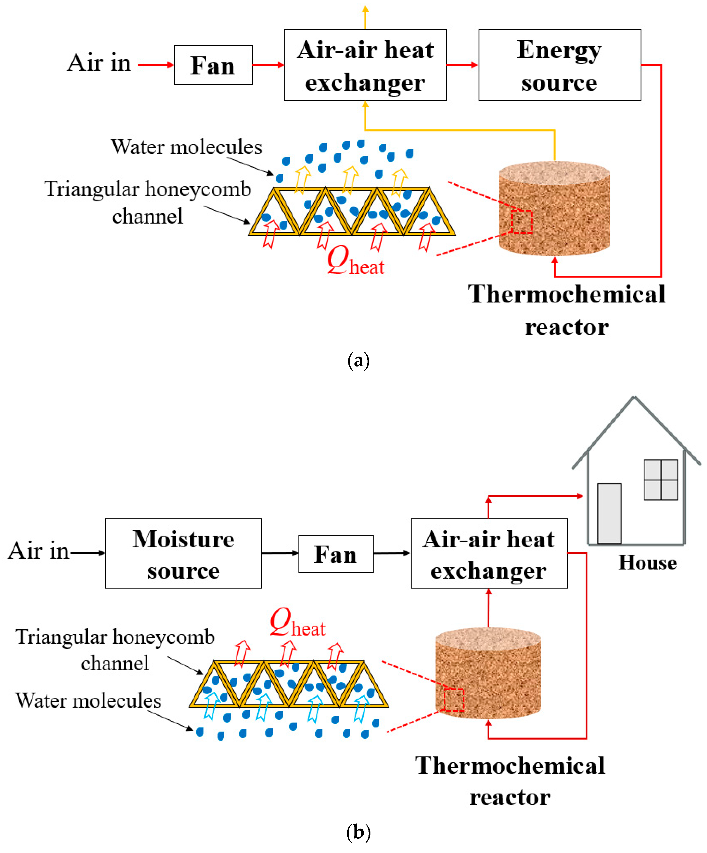
2.1. Thermochemical Energy Storage Process
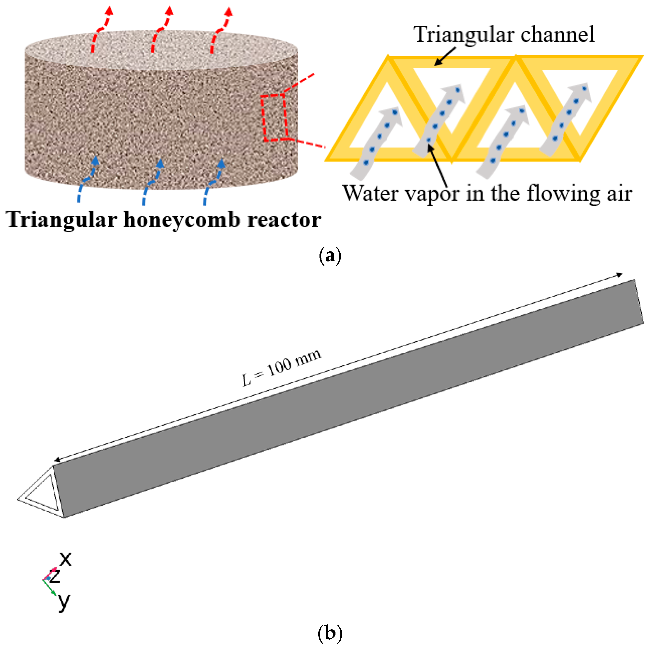
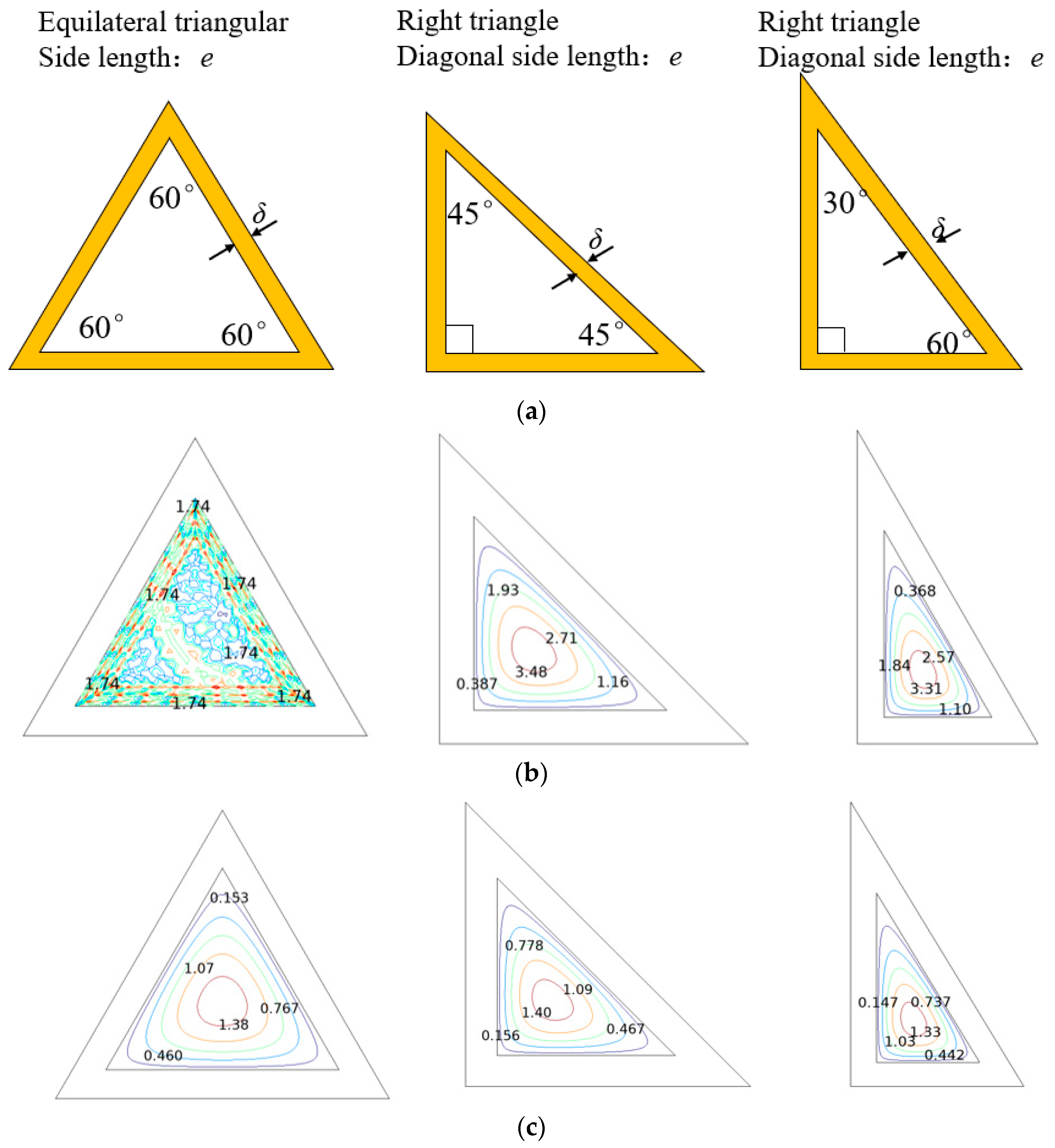
2.2. Details on the Triangular Honeycomb Reactor
3. Numerical Model Establishment
3.1. Numerical Model Description
- All triangular honeycomb channels are assumed to have the same heat and mass transfer performance. This assumption simplifies the calculation of the reactor’s thermal performance by treating each channel equivalently [22].
- The fluid inside the air channel is regarded as an ideal gas. This assumption is widely used in thermochemical modeling to streamline analysis, especially when dealing with air flow at moderate temperatures and pressures [23].
- Heat conduction and mass diffusion are considered within the triangular honeycomb channels, with the thermal conductivity, specific heat, and density of both air and zeolite 13X taken as functions of water vapor content. This enables the model to account for heat and mass transport processes during adsorption and desorption [24].
- It is assumed that the adsorption/desorption heat is sufficiently absorbed or diffused by the reactant layer, allowing for efficient energy storage and release within the reactor [25].
- Radiative heat transfer inside the reactor is considered negligible. This assumption is made to simplify the model, as the impact of radiation is minimal compared to convection and conduction at the temperature levels being studied.
3.2. Descriptions of Heat and Mass Transfer
3.2.1. Heat Transfer and Energy Balance
3.2.2. Mass Transfer and Mass Balance
3.2.3. Adsorption Kinetics
3.2.4. Initial and Boundary Conditions
3.3. Performance Indicators of the Proposed Thermochemical Reactor
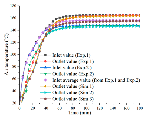
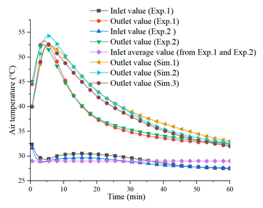
3.4. Model Validations
4. Results and Evaluations of the Proposed Reactor Configurations
4.1. Air Velocity Distribution
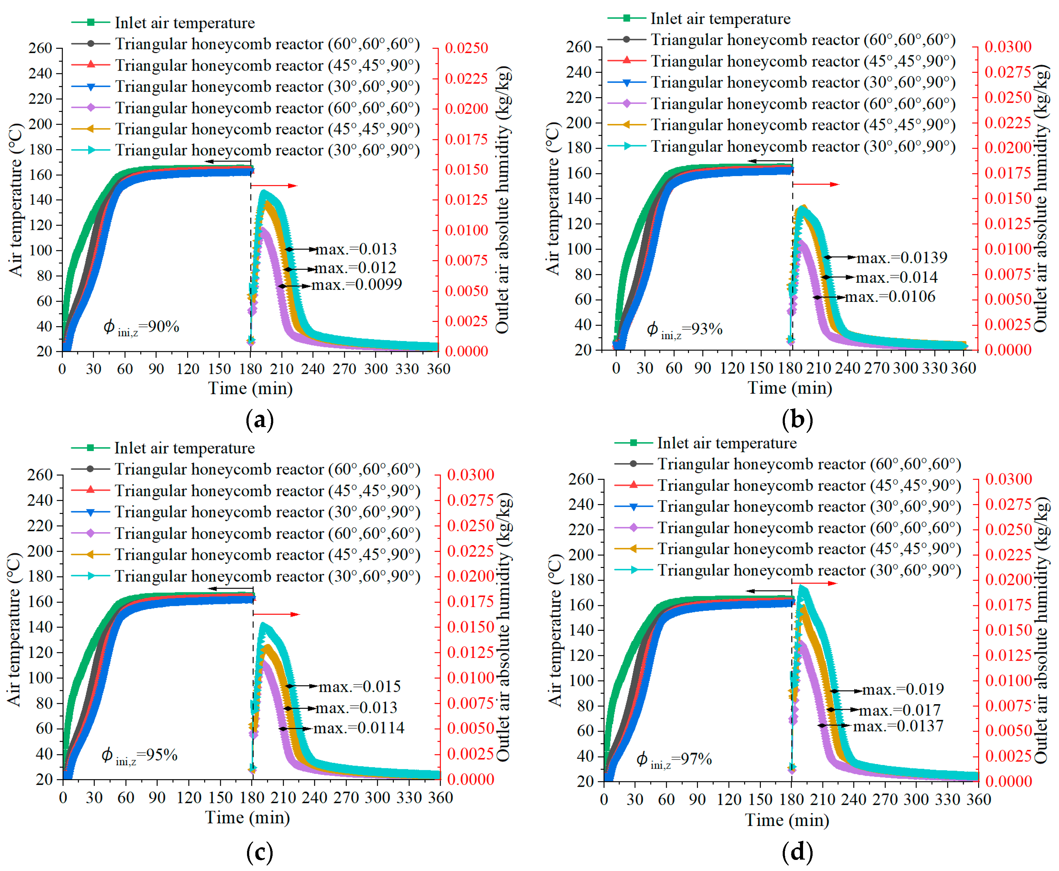
4.2. Air Temperature during the Charging Process
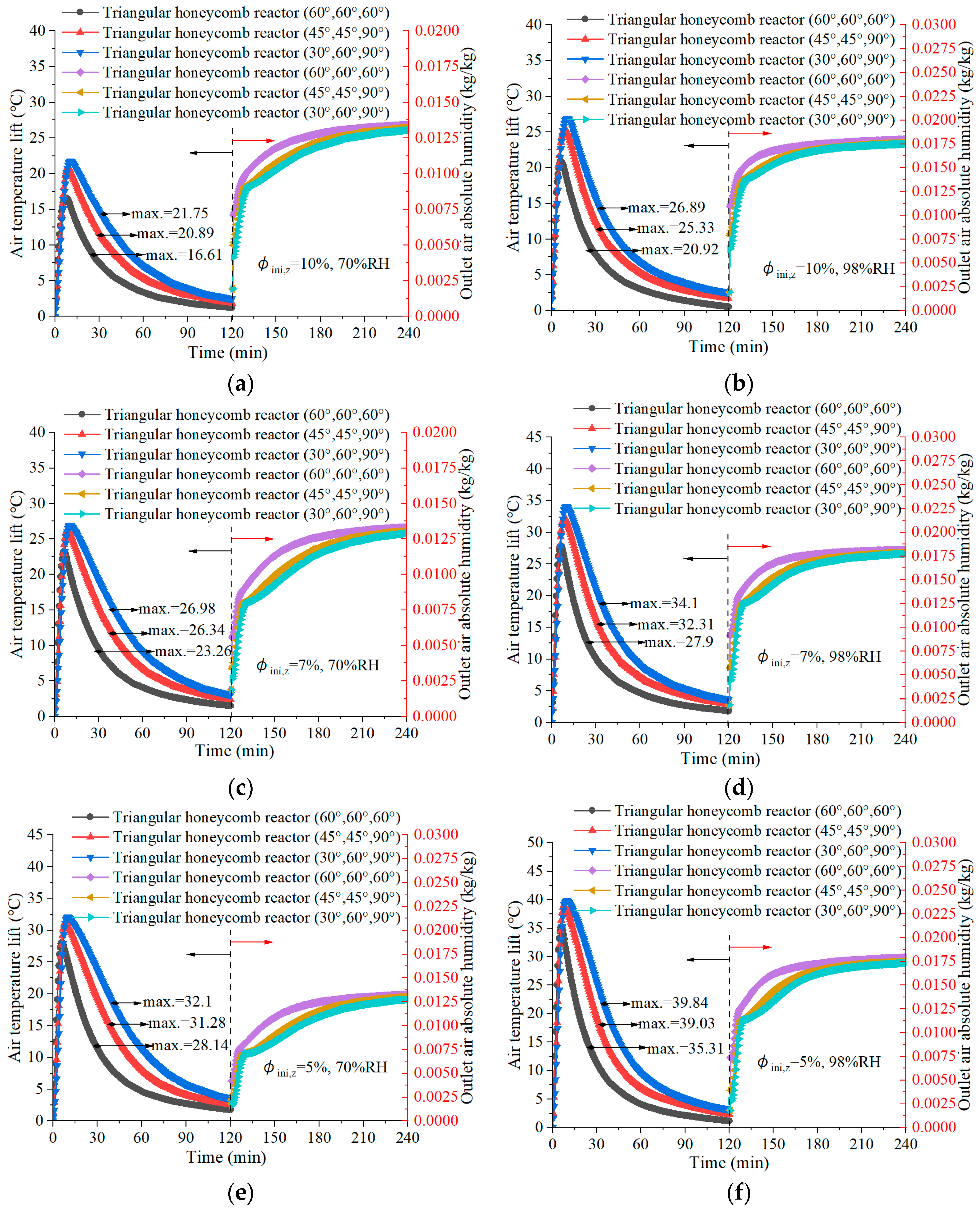
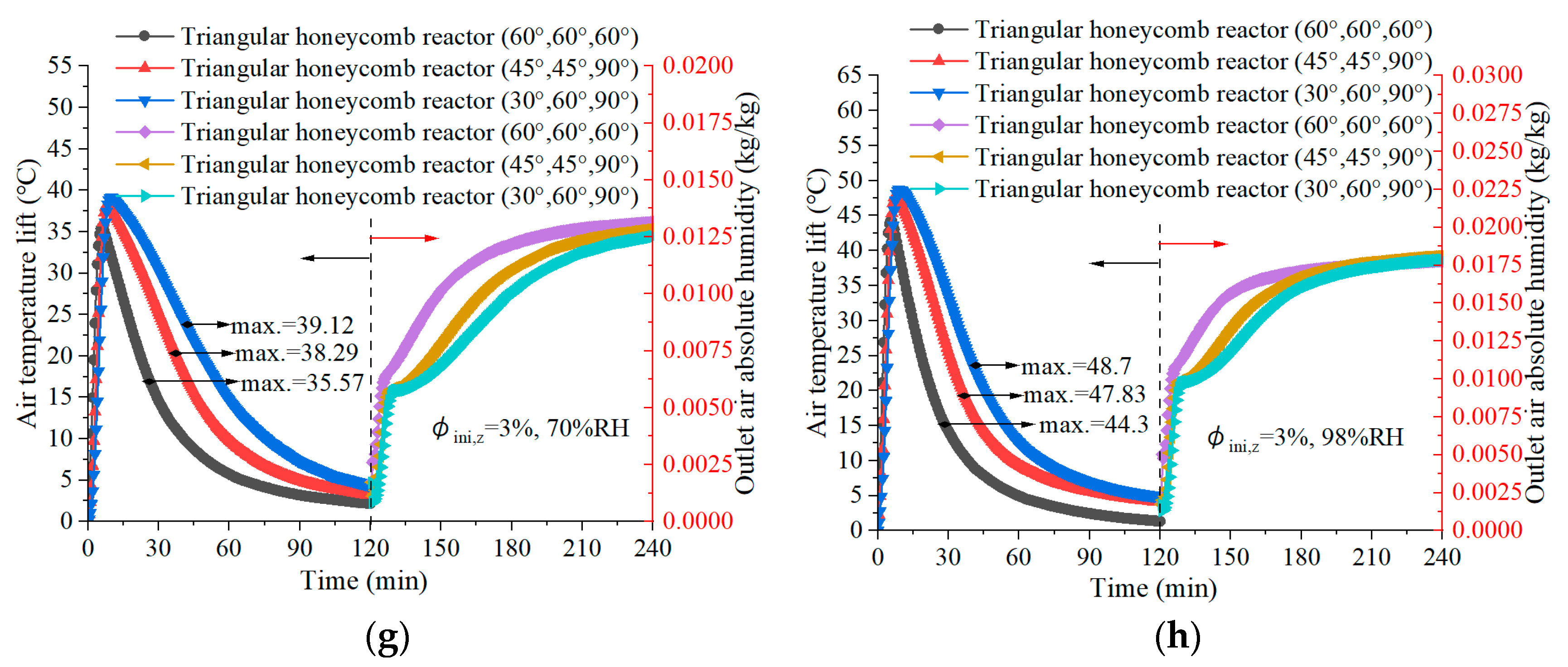
4.3. Air Temperature Lift in Discharging
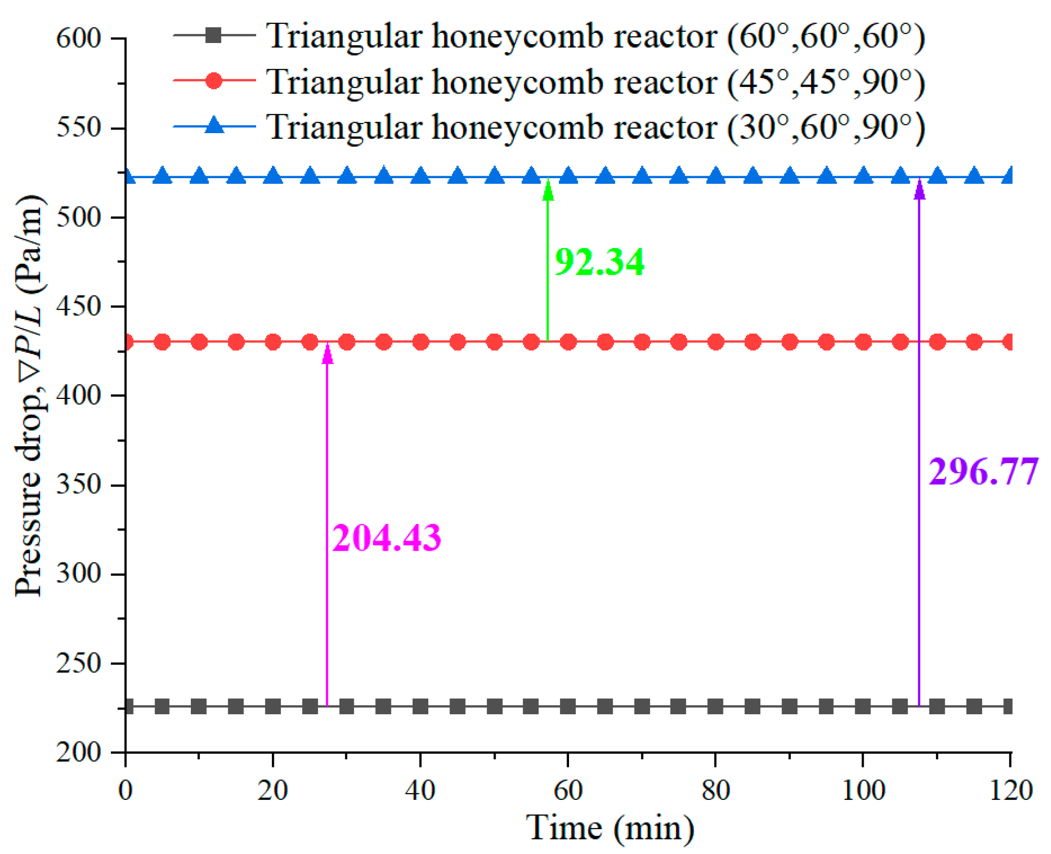
4.4. Pressure Drop during the Discharging Process
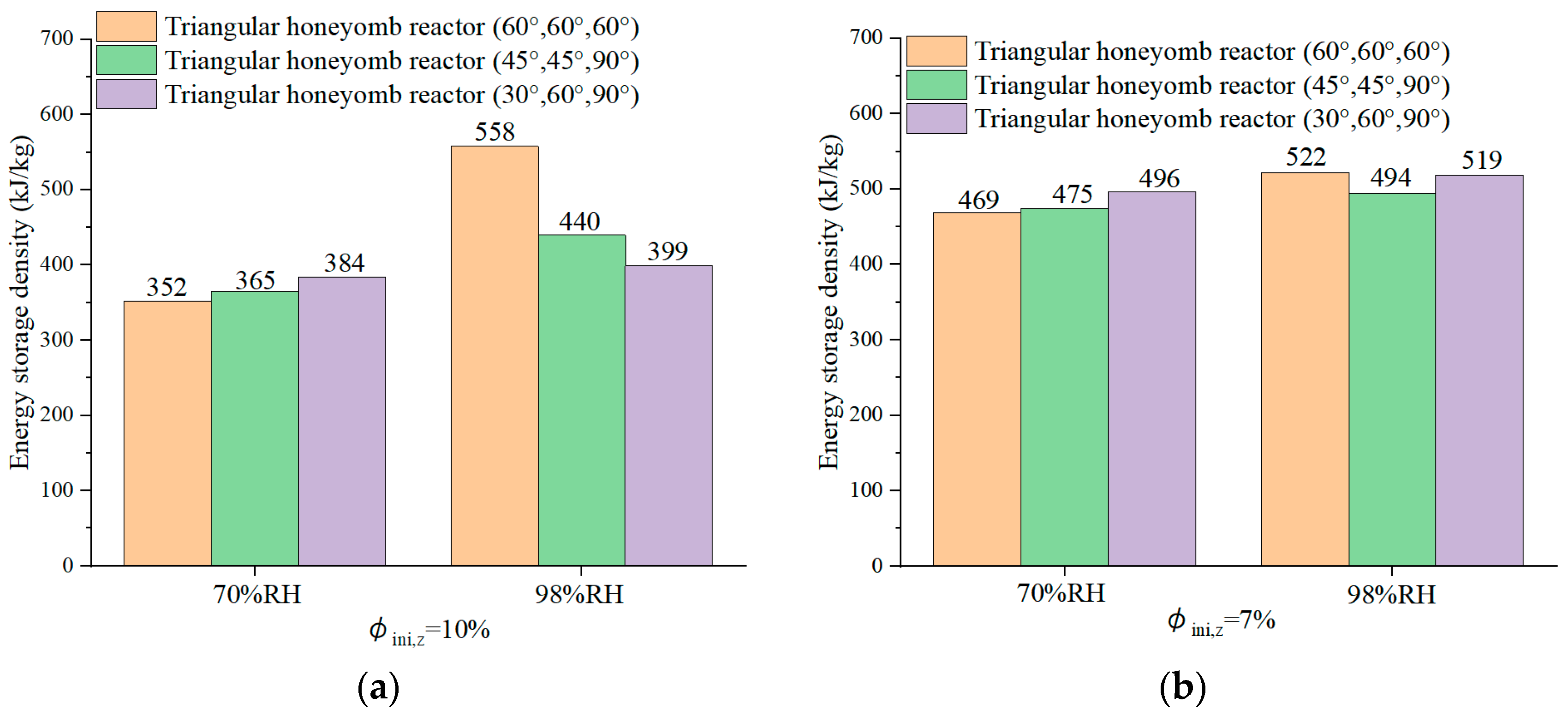
4.5. Energy Storage Density for Triangular Honeycomb Zeolite 13X Reactors
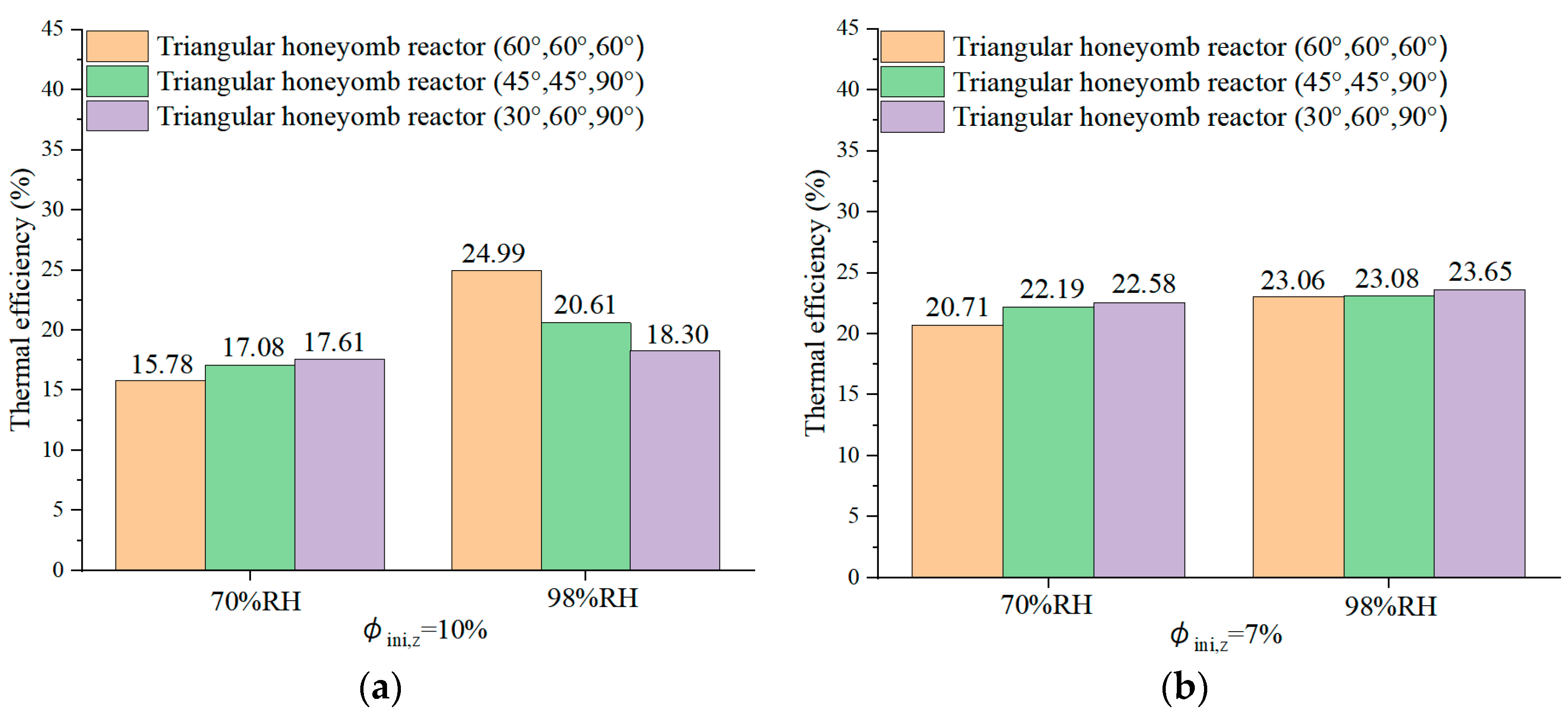
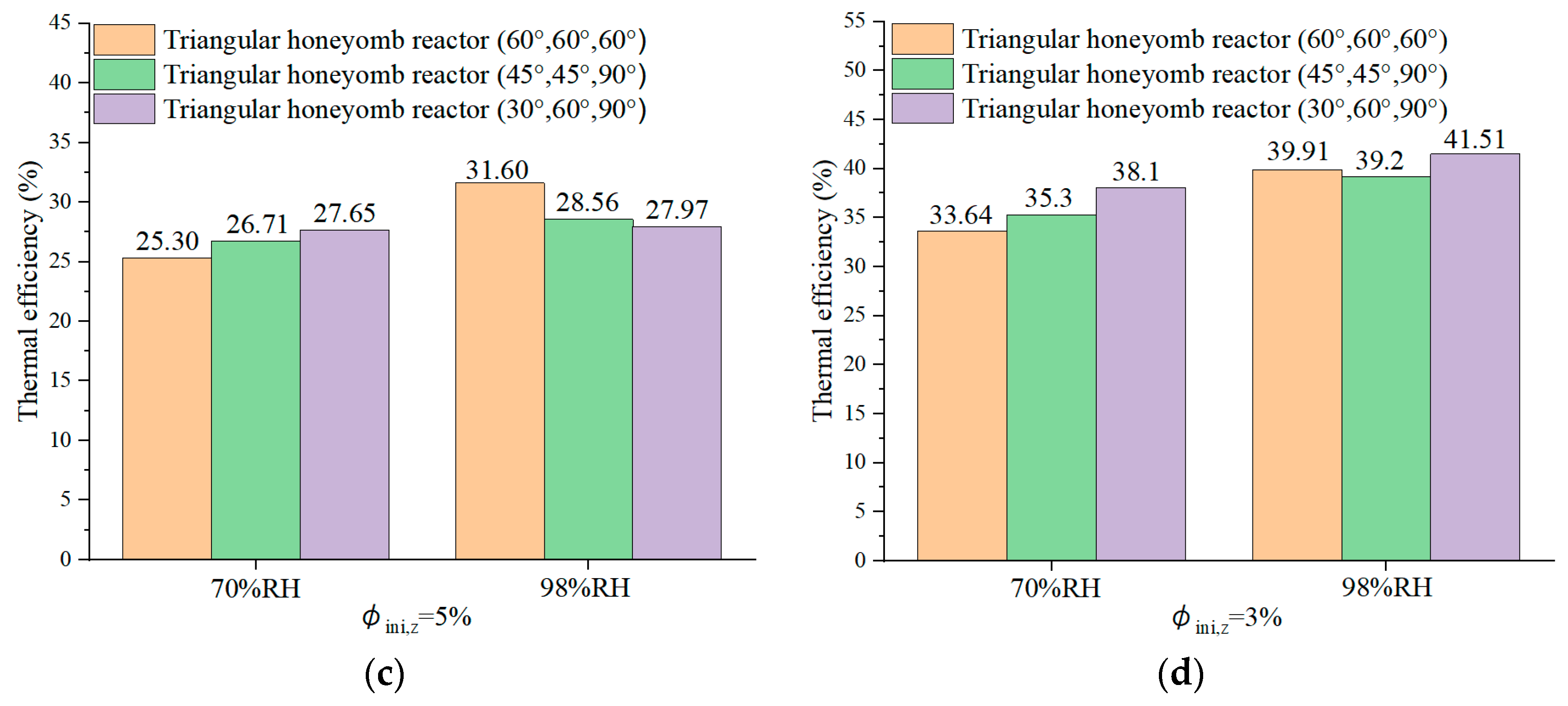
4.6. Reactor Round-Trip Thermal Efficiency
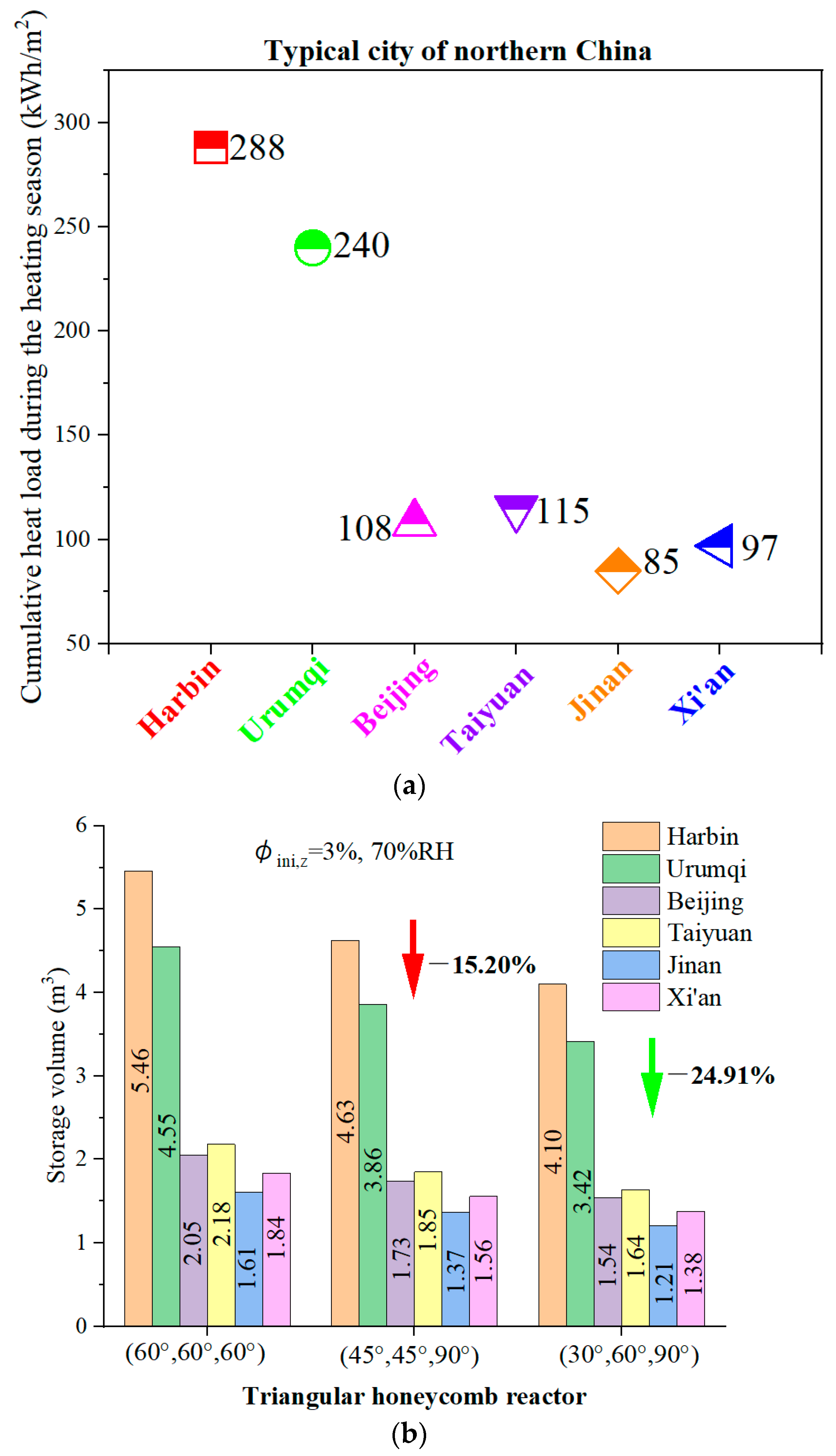
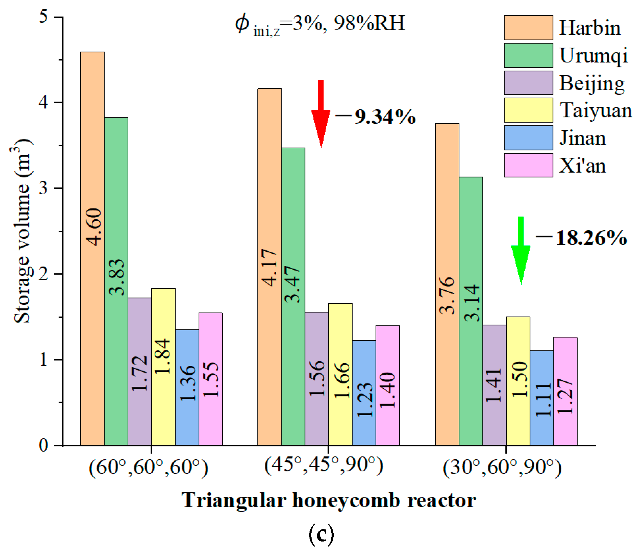
4.7. The Feasibility of the Novel Reactor for a Typical Home in Northern China
5. Conclusions
- The triangular honeycomb reactor with angles of 60°, 60°, and 60° achieves an energy storage density of 872 kJ/kg and thermal efficiency of 39.91%.
- The reactor with angles of 30°, 60°, and 90° achieves a maximum air temperature lift of 48.7 °C during the discharging process, underlining its superior discharging capabilities, which are essential for efficient low-carbon building heating. Meanwhile, the configuration obtained the highest thermal efficiency of 41.51%.
- Pressure loss is a critical parameter in evaluating the thermal performance of a reactor. Pressure drop analysis showed that the reactor with angles of 60°, 60°, and 60° achieves the lowest pressure drop of 226.12 Pa/m, while the reactors with angles of 45°, 45°, and 90° and 30°, 60°, and 90° experience higher pressure drops of 430.55 Pa/m and 522.89 Pa/m, respectively.
- A feasibility study for residential heating in northern China demonstrated that the reactor with angles of 30°, 60°, and 90° requires 24.91% less volume to meet daily heating demands compared to the other designs, showcasing its compact and efficient energy storage potential.
- This study provides valuable insights into the optimization of reactors for flexible energy management, allowing for integration with renewable energy sources like solar power and off-peak electricity.
Author Contributions
Funding
Data Availability Statement
Conflicts of Interest
Nomenclature
| Side length (mm) | ρ | Density | |
| Water concentration | Relative humidity | ||
| Specific heat | Channel thickness (mm) | ||
| Effective pore diffusion | Thermal efficiency (%) | ||
| Effective surface diffusion | Subscripts | ||
| Water vapor diffusivity in air | a | Air | |
| Heat of adsorption | amb | Ambient | |
| h | Specific enthalpy | char | Charging |
| Thermal power | cum | Cumulative | |
| Thermal conductivity | dis | Discharging | |
| Effective rate coefficient | eff | Effective | |
| L | Channel length (mm) | eq | Equilibrium |
| Molar mass | exp | Experimental | |
| m | Mass (kg) | ha | Humid air |
| Air mass velocity | in/out | Inlet/outlet of the air channel | |
| n | Vector (/) | ini | Initial |
| Pressure | l | Liquid water | |
| Atmospheric pressure | p | Pores of zeolite | |
| Saturation pressure | s | Surface | |
| Q | Energy | sim | Simulation |
| Universal gas constant | tot | Entire adsorbent layer, including pores, the solid part, and adsorbed water vapor) | |
| t | Time (s, h) | v | Water vapor |
| Temperature (K, °C) | w | Water | |
| v | Velocity (m/s) | z | Zeolite matrix (exclude pores and adsorbed water vapor) |
| Water vapor content in the air (kg/kg) | zm | Matrix of zeolite (excluding zeolite pores) | |
| Water vapor content in the pores of zeolite (kg/kg) | zp | Pores of zeolite (excluding zeolite matrix) | |
| Water vapor content in the matrix of the adsorbent, | |||
| Equilibrium adsorption amount | Abbreviation | ||
| ESD | Energy storage density | ||
| Greek symbols | MSOPE | Mean sum of the percentage errors | |
| Porosity | RH | Relative humidity | |
References
- Han, R.; Xing, S.; Wu, X.; Pang, C.; Lu, S.; Su, Y.; Liu, Q.; Song, C.; Gao, J. Relevant influence of alkali carbonate doping on the thermochemical energy storage of Ca-based natural minerals during CaO/CaCO3 cycles. Renew. Energy 2022, 181, 267–277. [Google Scholar] [CrossRef]
- Fopah Lele, A.; Kuznik, F.; Opel, O.; Ruck, W.K.L. Performance analysis of a thermochemical based heat storage as an addition to cogeneration systems. Energy Convers. Manag. 2015, 106, 1327–1344. [Google Scholar] [CrossRef]
- Chao, J.; Xu, J.; Yan, T.; Wang, P.; Huo, X.; Wang, R.; Li, T. Enhanced thermal conductivity and adsorption rate of zeolite 13X adsorbent by compression-induced molding method for sorption thermal battery. Energy 2022, 240, 122797. [Google Scholar] [CrossRef]
- Scapino, L.; Zondag, H.A.; Van Bael, J.; Diriken, J.; Rindt, C.C.M. Sorption heat storage for long-term low-temperature applications: A review on the advancements at material and prototype scale. Appl. Energy 2017, 190, 920–948. [Google Scholar] [CrossRef]
- Zeng, C. Development and Investigation of a Novel Thermochemical Energy Storage Reactor for Residential Use. Ph.D. Thesis, Coventry University, Coventry, UK, 2020. [Google Scholar]
- Feng, C.; E, J.; Han, W.; Deng, Y.; Zhang, B.; Zhao, X.; Han, D. Key technology and application analysis of zeolite adsorption for energy storage and heat-mass transfer process: A review. Renew. Sustain. Energy Rev. 2021, 144, 110954. [Google Scholar] [CrossRef]
- Rönsch, S.; Auer, B.; Kinateder, M.; Gleichmann, K. Zeolite Heat Storage: Key Parameters from Experimental Results with Binder-Free NaY. Chem. Eng. Technol. 2020, 43, 2530–2537. [Google Scholar] [CrossRef]
- Kant, K.; Pitchumani, R. Advances and opportunities in thermochemical heat storage systems for buildings applications. Appl. Energy 2022, 321, 119299. [Google Scholar] [CrossRef]
- Michel, B.; Mazet, N.; Neveu, P. Experimental investigation of an open thermochemical process operating with a hydrate salt for thermal storage of solar energy: Local reactive bed evolution. Appl. Energy 2016, 180, 234–244. [Google Scholar] [CrossRef]
- Weber, R.; Asenbeck, S.; Kerskes, H.; Drück, H. SolSpaces—Testing and Performance Analysis of a Segmented Sorption Store for Solar Thermal Space Heating. Energy Procedia 2016, 91, 250–258. [Google Scholar] [CrossRef]
- Zhang, H.; Liu, S.; Shukla, A.; Zou, Y.; Han, X.; Shen, Y.; Yang, L.; Zhang, P.; Kusakana, K. Thermal performance study of thermochemical reactor using net-packed method. Renew. Energy 2022, 182, 483–493. [Google Scholar] [CrossRef]
- Ji, W.; Zhang, H.; Liu, S.; Li, Y.; Wang, Z.; Deng, S. A metal mesh net-packed method for improving thermochemical energy storage reactor performance by increasing the void fraction. Appl. Therm. Eng. 2023, 225, 120248. [Google Scholar] [CrossRef]
- Zeng, C.; Liu, S.; Yang, L.; Han, X.; Song, M.; Shukla, A. Investigation of a three-phase thermochemical reactor through an experimentally validated numerical modelling. Appl. Therm. Eng. 2019, 162, 114223. [Google Scholar] [CrossRef]
- de Boer, R.; Smeding, S.F.; Zondag, H.A.; Krol, G. Development of a Prototype System for Seasonal Solar Heat Storage Using an Open Sorption Process; ECN: Petten, The Netherlands, 2014; pp. 28–30. [Google Scholar]
- Tatsidjodoung, P.; Le Pierrès, N.; Heintz, J.; Lagre, D.; Luo, L.; Durier, F. Experimental and numerical investigations of a zeolite 13X/water reactor for solar heat storage in buildings. Energy Convers. Manag. 2016, 108, 488–500. [Google Scholar] [CrossRef]
- van Alebeek, R.; Scapino, L.; Beving, M.A.J.M.; Gaeini, M.; Rindt, C.C.M.; Zondag, H.A. Investigation of a household-scale open sorption energy storage system based on the zeolite 13X/water reacting pair. Appl. Therm. Eng. 2018, 139, 325–333. [Google Scholar] [CrossRef]
- Aydin, D.; Casey, S.P.; Chen, X.; Riffat, S. Novel “open-sorption pipe” reactor for solar thermal energy storage. Energy Convers. Manag. 2016, 121, 321–334. [Google Scholar] [CrossRef]
- Casey, S.P.; Aydin, D.; Elvins, J.; Riffat, S. Salt impregnated desiccant matrices for ‘open’ thermochemical energy conversion and storage—Improving energy density utilisation through hygrodynamic & thermodynamic reactor design. Energy Convers. Manag. 2017, 142, 426–440. [Google Scholar] [CrossRef]
- Zhang, Y.; Hu, M.; Chen, Z.; Su, Y.; Riffat, S. Exploring a novel tubular-type modular reactor for solar-driven thermochemical energy storage. Renew. Energy 2024, 221, 119767. [Google Scholar] [CrossRef]
- Johannes, K.; Kuznik, F.; Hubert, J.-L.; Durier, F.; Obrecht, C. Design and characterisation of a high powered energy dense zeolite thermal energy storage system for buildings. Appl. Energy 2015, 159, 80–86. [Google Scholar] [CrossRef]
- Han, X.; Zeng, C.; Liu, S.; Wang, Z.; Deng, S.; Zhang, H. Numerical study on the heat and mass transfer in charging and discharging processes of a triangular honeycomb thermochemical energy storage reactor. Appl. Therm. Eng. 2023, 219, 119499. [Google Scholar] [CrossRef]
- Cheng, D.; Peters, E.A.J.F.; Kuipers, J.A.M. Performance study of heat and mass transfer in an adsorption process by numerical simulation. Chem. Eng. Sci. 2017, 160, 335–345. [Google Scholar] [CrossRef]
- Zeng, C.; Liu, S.; Shukla, A.; Yang, L.; Han, X.; Shen, Y. Numerical modelling of the operational effects on the thermochemical reactor performance. Energy Build. 2021, 230, 110535. [Google Scholar] [CrossRef]
- Cheng, D.; Peters, E.A.J.F.; Kuipers, J.A.M. Numerical modelling of flow and coupled mass and heat transfer in an adsorption process. Chem. Eng. Sci. 2016, 152, 413–425. [Google Scholar] [CrossRef]
- Wang, W.; Pan, Q.; Wang, R.; Ge, T. Modeling and optimization of a honeycombed adsorbent bed for efficient moisture capture. Appl. Therm. Eng. 2022, 200, 117717. [Google Scholar] [CrossRef]
- Kim, H.; Cho, H.J.; Narayanan, S.; Yang, S.; Furukawa, H.; Schiffres, S.; Li, X.; Zhang, Y.B.; Jiang, J.; Yaghi, O.M.; et al. Characterization of Adsorption Enthalpy of Novel Water-Stable Zeolites and Metal-Organic Frameworks. Sci. Rep. 2016, 6, 19097. [Google Scholar] [CrossRef]
- Glueckauf, E. Theory of chromatography. Part 10. Formula for diffusion into spheres and their application to chromatography. Trans. Faraday Soc. 1955, 51, 1540–1551. [Google Scholar] [CrossRef]
- Ruthven, D.M. Principles of Adsorption and Desorption Processes; John Wiley & Sons: New York, NY, USA, 1984. [Google Scholar]
- Parsons, B.K.; Pesaran, A.A.; Bharathan, D.; Shelpuk, S. Evaluation of thermally activated heat pump/desiccant air conditioning systems and components. In Evaluation of Thermally Activated Heat Pump/Desiccant Air Conditioning Systems and Components; SERI/TR-252-3116; Oak Ridge National Laboratory: Oak Ridge, TN, USA, 1987. [Google Scholar]
- Kuznik, F.; Gondre, D.; Johannes, K.; Obrecht, C.; David, D. Numerical modelling and investigations on a full-scale zeolite 13X open heat storage for buildings. Renew. Energy 2019, 132, 761–772. [Google Scholar] [CrossRef]
- Ahn, H.; Lee, C.-H. Effects of capillary condensation on adsorption and thermal desorption dynamics of water in zeolite 13X and layered beds. Chem. Eng. Sci. 2004, 59, 2727–2743. [Google Scholar] [CrossRef]
- Han, X.; Zeng, C.; Liu, S.; Cheng, Y.; Zhu, X. Maximizing Thermal Performance in Triangular Honeycomb Thermochemical Reactors: Structural and Operating Parameter Studies. Energy 2024, 308, 132743. [Google Scholar] [CrossRef]
- Shukla, A.; Tiwari, G.N.; Sodha, M.S. Experimental study of effect of an inner thermal curtain in evaporative cooling system of a cascade greenhouse. Sol. Energy 2008, 82, 61–72. [Google Scholar] [CrossRef]
- Allouche, Y.; Varga, S.; Bouden, C.; Oliveira, A.C. Validation of a CFD model for the simulation of heat transfer in a tubes-in-tank PCM storage unit. Renew. Energy 2016, 89, 371–379. [Google Scholar] [CrossRef]
- Dolado, P.; Lazaro, A.; Marin, J.M.; Zalba, B. Characterization of melting and solidification in a real-scale PCM–air heat exchanger: Experimental results and empirical model. Renew. Energy 2011, 36, 2906–2917. [Google Scholar] [CrossRef]
- Tang, J.; Sun, X.; Wang, P. Energy consumption analysis on the heating for different climates rural residential areas. Heat. Vent. Air Cond. 2022, 52, 37–41. [Google Scholar]


| Triangular honeycomb structure | 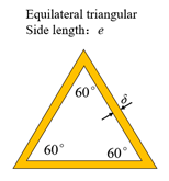 |  | 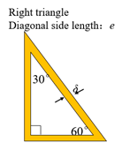 |
| Side length (mm) | 2.13, 2.13, 2.13 | , , 2.13 | , , 2.13 |
| Single-channel thickness (mm) | 0.265 | 0.265 | 0.265 |
| Channel length (mm) | 100 | 100 | 100 |
| Perimeter of inner channel (mm) | |||
| Zeolite mass (kgzeolite) | 3.38 | 4.03 | 4.26 |
| Channel number | 48,808 | 67,560 | 70,839 |
| Reactor volume (m3) | 0.0196 | 0.0196 | 0.0196 |
| Air | |
| Zeolite 13X | |
| Initial Conditions | Inlet Air Conditions | |
|---|---|---|
| Charging | ||
| Discharging | , 7%, 5%, 3% | |
| Outlet air conditions [22] | ||
| Outlet atmospheric air pressure | ||
| All variables have zero normal gradients at the outlet. | ||
| Interface boundary conditions [22] | ||
| Boundary conditions at the air–adsorbent interface layer are derived from mass and energy balances as follows: | ||
| Wall boundary conditions | ||
| There is no heat flux for the adsorbent layer. | ||
| Description | Unit | Equation | ||
|---|---|---|---|---|
| Charging | Instantaneous heat transfer to adsorbents | W | (8) | |
| Cumulation of thermal energy by adsorbents | J | (9) | ||
| Discharging | Instantaneous heat release from adsorbents | W | (10) | |
| Release of cumulated thermal energy by adsorbents | J | (11) | ||
| Energy storage density | J/kg | (12) | ||
| Reactor thermal efficiency | % | (13) | ||
| Charging Process (, ) | |
 (a) | |
| [21] | |
| Discharging process ( and , ) | |
 (b) | 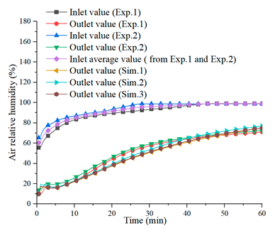 (c) |
| [21] | [21] |
| Reactor | Process | Operating Conditions | Increment Rate of Peak Air Temperature Lift Compared with Triangular Honeycomb Reactor with Angles of 60°, 60°, and 60° |
|---|---|---|---|
| Triangular honeycomb reactor with angles of 45°, 45°, and 90° | Charging | 24.82% | |
| 28.93% | |||
| 20.71% | |||
| 25.22% | |||
| Discharging | , RH = 70% | 25.77% | |
| , RH = 98% | 21.08% | ||
| , RH = 70% | 13.24% | ||
| , RH = 98% | 15.81% | ||
| , RH = 70% | 11.16% | ||
| , RH=98% | 10.54% | ||
| , RH = 70% | 7.65% | ||
| , RH = 98% | 7.97% | ||
| Triangular honeycomb reactor with angles of 30°, 60°, and 90° | Charging | 39.32% | |
| 39.12% | |||
| 38.94% | |||
| 40.86% | |||
| Discharging | , RH = 70% | 30.95% | |
| , RH = 98% | 28.54% | ||
| , RH = 70% | 15.99% | ||
| , RH = 98% | 22.22% | ||
| , RH=70% | 14.07% | ||
| , RH = 98% | 12.83% | ||
| , RH = 70% | 9.98% | ||
| , RH = 98% | 9.93% |
Disclaimer/Publisher’s Note: The statements, opinions and data contained in all publications are solely those of the individual author(s) and contributor(s) and not of MDPI and/or the editor(s). MDPI and/or the editor(s) disclaim responsibility for any injury to people or property resulting from any ideas, methods, instructions or products referred to in the content. |
© 2024 by the authors. Licensee MDPI, Basel, Switzerland. This article is an open access article distributed under the terms and conditions of the Creative Commons Attribution (CC BY) license (https://creativecommons.org/licenses/by/4.0/).
Share and Cite
Han, X.; Zeng, C.; Zhu, Z.; Sun, Y.; Zhao, X. Investigation of a Novel Thermochemical Reactor for Medium- and Low-Temperature Heating Applications in Buildings. Buildings 2024, 14, 3192. https://doi.org/10.3390/buildings14103192
Han X, Zeng C, Zhu Z, Sun Y, Zhao X. Investigation of a Novel Thermochemical Reactor for Medium- and Low-Temperature Heating Applications in Buildings. Buildings. 2024; 14(10):3192. https://doi.org/10.3390/buildings14103192
Chicago/Turabian StyleHan, Xiaojing, Cheng Zeng, Zishang Zhu, Yanyi Sun, and Xudong Zhao. 2024. "Investigation of a Novel Thermochemical Reactor for Medium- and Low-Temperature Heating Applications in Buildings" Buildings 14, no. 10: 3192. https://doi.org/10.3390/buildings14103192