Abstract
Braces equipped with dissipative devices are among the most widespread methods for the seismic strengthening of seismically prone reinforced concrete (RC) frames. It allows for high reductions in seismic vulnerability with inexpensive, quickly executed interventions. They can often be carried out mainly at the exterior, resulting in interruptions of use that are limited both in time and to only small portions of the building. The design methods of dissipative devices are based on the extensive use of pushover analyses (POA). POA is capable of highlighting the structural deficiencies of the building and comparing the performances of design performed according to different methods and sizing criteria. In the present work, with reference to a case study represented by a four-story spatial frame having characteristics representative of design and construction common practice of the 1970s in Southern European countries, the performances of three different design methods were evaluated and compared. The examined procedures differ, including the following: (i) methods for estimating the peak displacement response of the nonlinear systems, namely (i1) the well-known equal displacement rule and (i2) the equivalent (secant) stiffness and damping rule, and (ii) criteria for distributing stiffness and strength of the braces along the height, namely (ii1) the distribution of stiffness and strength proportionally to those of the frame and (ii2) methods that vary the stiffness and strength along the height in order to minimize the eventual irregularity in elevation of the bare frame. The effectiveness of the procedures was checked by both POA and nonlinear response history analysis, the latter performed assuming both unidirectional and bidirectional input. The stiffness was found to increase by about 10 times and the strength between 7.5 to 3.7 times depending on the design method, and reduction in the displacements ranged between 31% and 42% compared to the values of the original frame. The pros and cons of each procedure are summarized, as all procedures are able to provide brace designs that meet the performance requirements set during the design phase.
1. Introduction
The seismic design principles introduced with capacity design method have highlighted the need to seismically adapt many of the reinforced concrete frames designed in the 1960s and 1970s without earthquake-resistant design rules. Seismic strengthening techniques are very diversified [1]. Thus, the choice of intervention technique must be made in relation to the characteristics and weaknesses of the structure to be retrofitted [2].
For structures designed with anti-seismic design criteria that are now outdated, local interventions are often sufficient, such as shear reinforcement of nodes [2,3,4,5], beams, and columns [6,7,8,9]; confinement interventions in the critical regions where plastic hinges can take place [10,11]; increase in column sections through jacketing [12]; and connection and strengthening of non-structural elements such as infill panels [13]. When the structure as a whole has insufficient stiffness and resistance to horizontal actions, the use of braces is often chosen as a strengthening solution [14,15,16,17]. When the structure is equipped with construction details that are insufficient to avoid loss of resistance due to seismic actions [18] as well as adequate cyclic ductility and dissipative capacity, the introduction of passive energy dissipation systems is one of the most common solutions [19,20,21,22,23,24,25,26]. The combination of these two last strategies, namely the use of dissipative braces, constitutes one of the most effective techniques, as demonstrated by the numerous applications throughout the world since the end of the 1980s [27,28].
A comprehensive review of passive energy dissipation systems in steel braces was reported in [29], where a section dedicated to evaluating seismic retrofitting techniques can be found. The review highlighted that, in strengthening any existing structure, a preliminary assessment of the whole weakness of the structure is mandatory [30,31]. The use of dissipative braces aims at providing the increment of stiffness and resistance that characterizes the strengthening method based on the insertion of braces in MRFs as well as large and stable energy dissipation capacity, which characterizes the cyclic behavior of dissipative devices.
It is noteworthy that braces design must take into account the risk of an excessive increase in axial load in the columns and in the actions transmitted to the foundation. In this context, the use of braces with hysteretic or friction dissipative devices or buckling restrained braces allows to overcome the above-mentioned problems since the stiffness and resistance of the braces can be tuned separately [32,33,34,35]. Braces equipped with hysteretic dissipative devices can significantly reduce inter-story drifts and dissipate large amounts of energy, preserving the frame elements from plasticization and damage accumulation due to repeated ground motions, which usually affect RC moment-resistant frames [36,37,38].
In this field, since the 1980s, dissipative braces design techniques have been proposed, exploiting the evolution of the method for predicting the seismic response of framed structures. Efficient design procedures have been established, aimed at solving the main issues that arise during the design phase: choice of the performances that must be guaranteed, design of the global values of stiffnessand resistance of the braces, distribution of stiffness and resistance of the braces in elevation and in plan (this issue is critical for in-elevation or in-plan irregular structures), and executive design of individual braces and dissipative devices in relation to the specific characteristics.
With reference to the performances to be guaranteed, given the high stiffness and the large dissipation capacities that dissipative braces are able to guarantee, from the first formulations [32] to the more recent ones [19,20,22,39,40], the braces are designed to avoid the plasticization of the elements of the pre-existing frame and the damage of the non-structural elements.
Regarding the formulation of the first methods [32], in almost all procedures, an equivalent SDOF is used for the evaluation of the global stiffness and the resistance to be assigned to the bracing systems. In this regard, recent seismic codes [41,42,43] provide two procedures for estimating the peak displacement response of the nonlinear systems, namely the well-known equal displacement rule (EDR1) (suitably modified in the field of rigid structures) and the “substitute structure procedure” proposed by Shibata and Sozen [44], according to which the displacement of a nonlinear MDOF structure is estimated, consistently with the equivalent linearization technique [45], by evaluating the peak displacement of an elastic SDOF with equivalent damping and (secant) stiffness. The latter procedure is denoted in the following as ED2.
Regarding the distribution of stiffness and resistance in elevation and plan, there are two most-followed approaches: distributing stiffness and resistance proportionally to the characteristics of the structure to be strengthened [22,46] and distributing stiffness and resistance in such a way as to correct the irregularities in plan and elevation that are present in the structure [19,20,47,48].
In this context, several researchers implemented the direct displacement-based design (DBD) procedure [49,50,51,52,53,54,55,56,57,58] to design the dampers. The procedure proposed by Kim and Choi [49] resembles the capacity spectrum method. In this approach, a performance point is evaluated as the point where the displacement demand of the structures coincides with their plastic deformation capacity, by means of the acceleration displacement response spectrum. To evaluate the required damping to meet the target displacement criteria, instead of using a random hit-and-trial method, the damping is calculated as the difference between the effective damping and the damping provided by the structure. In the case of hysteretic dampers, iterations are necessary because incorporating the devices increases the structure’s stiffness, which ultimately increases the overall stiffness. The procedure was applied to 10-story and 20-story buildings, and the results demonstrate the method’s effectiveness, as the structures modeled using this approach had maximum displacements equal to the target displacement.
Changing the performances that must be guaranteed, Bergami et al. [40] elaborated a technique based on capacity spectrum characterized by two design aims: avoiding both any structural and non-structural damage, the latter achieved by limitation of the base-shear.
Mazza and Vulcano [51] proposed a design method based on the DBD of dissipative braces, aiming at controlling the inter-story drift. The braces are designed at each story by means of the proportional stiffness criterion (PSC), in which the selected stiffness of braces is proportional to that of the unbraced frame. To this aim, an iterative approach was adopted to assign the ratio of these stiffnesses depending on the strength of the unbraced frame.
Di Cesare and Ponzo [20] developed a procedure to design the mechanical characteristics of dissipative braces for RC structures, assuming the displacement on the top story as a control parameter. Initially, the PSC is assumed. Then, the stiffness and strength of each story is modified to control the inter-story along the height of the building in order to comply with the in-elevation regularity criteria of the seismic codes. The procedure was applied to different case studies. From the results, it was found that the hysteretic energy dissipative braces were effective to obtain the required performance of the structure, confirming the efficiency of the proposed method. The method also highlighted criteria to avoid unnecessary overloading on structural members.
Barbagallo et al. [59] developed a design method for seismic retrofitting of existing RC frames through a hybrid force–displacement based design method. RC frames with different deficiencies were analyzed, namely frames designed to withstand gravity load only, frames with low-strength concrete, or frames designed for a low-seismicity area. The method aims at providing, by means of an iterative procedure, a direct control of inter-story drift, ductility demands, and minimum shear strength to accomplish the requirement at the serviceability limit state. To this aim, optimal values of the behavior factor were selected, and the ratio of lateral strength to seismic shear demand constant along the height of the frame were assumed.
Ferraioli and Lavino [21] proposed a design method aiming at improving the procedure of Mazza et al. [19], established on displacement-based design (DBD) by using the capacity spectrum method. The paper addressed some critical points that were not incorporated in the previous methods: dissipative braces and frame interaction, which produces an increment of the axial load in the columns with consequent decreasing of the available ductility; torsional effects in asymmetric buildings; potential activation of soft story mechanisms; effect of the modification of the first modal shape and therefore of the corresponding distribution of seismic forces along the height of the frame due to the modification of the resisting system from moment-resistant frames (MRFs) to concentric braced frames (CBFs); and effects of the higher vibration modes in high-rise frames. The proposed procedure is divided into two parts: The first one concerns the design of dissipative braces; in the second pert, the position and properties are defined, varying the design force pattern to incorporate the higher mode contributions. Adaptive pushover analysis is advised to accurately estimate the displacement demand and ductility demand distribution. To check the validity of the design method, nonlinear time history analysis was performed on a 2DRC frame and then on a real school building. The results showed the effectiveness of the method in addressing the aforementioned issues. It was also found that the procedure is able to distribute the damper stiffness and strength properly along the height of the structure and thus gives uniform story drift distribution, resulting in the reduction in inter-story drift.
Bruschi et al. [22] proposed another procedure for the seismic upgrading of a structure using dissipative braces based on the concept of the equivalent elastic high-damped SDOF system, which has equivalent viscous damping and secant stiffness at the performance point, similarly to what that of [49]. Initially, a step-by-step procedure is performed to evaluate the global properties of the damped bracing system. Thus, the capacity curve of the frame is determined by means of pushover analysis; then, a target displacement is identified, and a tentative equivalent SDOF bilinear curve of the braced frame is constructed. Afterward, an iterative procedure is used to find the equivalent viscous damping ratio of the damped brace system together with the actual final stiffness and strength of the damped braces. The final configuration is found when the braced frame seismic demand matches the required target displacement on the damped acceleration displacement response spectra. Once the global parameters of the equivalent SDOF are found, the stiffness and strength of the braces are distributed along the height of the structure proportionally to the characteristic of the frame to be strengthened. Lastly, the damped braces are positioned within the story of the structure.
Recently, Monti et al. [60] proposed a DDB non-iterative procedure for gravity-load-designed reinforced concrete frames. The procedure aims at limiting the inter-story drifts and avoiding damage in the RC columns by a simplified modeling of the existing frame through so-called stick models. The optimal sizing of the braces and the equivalent viscous damping are found by equivalent linearization of the behavior of each story. Moreover, independent checks of local fragile mechanisms, namely beam and column shear collapse and premature collapse of the beam–column joints, are always required in order to prevent local mechanism that could defeat the efficiency of the strengthening method.
In the following sections, through a case study represented by a four-story spatial frame having characteristics representative of design and construction common practice of the 1970s in Southern European countries, the effectiveness of two of the aforementioned procedures are compared with a simpler one, based on the principles of current seismic codes. The latter pursues performance-based design through the force approach, with the control of the displacement demand.
In detail, the two procedures that are compared are the one proposed by Di Cesare and Ponzo [20] (DCP), based on the equal displacement rule EDR1, and the procedure proposed by Bruschi, Quaglini, and Calvi [22] (BQC), based on the equivalent damping approach ED2. These two procedures are chosen because, in addition to their characterization by a balance between the simplicity of the method and the effectiveness of the resulting design, they also (i) use the two different above-mentioned methods for the estimation of the displacement required by the earthquake and (ii) use different criteria to design stiffness and strength of the braces at each story, namely the BQC method designs the stiffness and strength of the braces along the height, proportionally to those of the structure to be strengthened (SRPC), while the DPC method provides for a brace modification only if the strengthened structure does not satisfy the criteria of regularity in height of the regulatory codes.
The third method presented in the current research study, denoted as the CAD method, works with a hybrid approach for required displacement assessment and is developed aiming to obtain a uniform inter-story drift.
2. Design Methods
Most of the design methods for retrofitting frames by dissipative braces integrate the pushover analysis of the multi-degree-of-freedom (MDOF) model of the bare frame (BF) with the response spectrum analysis of an equivalent single-degree-of-freedom (SDOF) system to estimate the initial global nonlinear displacement response of the frame to be strengthened. Then, the global strengthening dissipative system parameters are designed by setting a required performance goal, usually identified with a maximum total drift. Then, the global parameters of the SDOF-braced frame are converted into those of the corresponding MDOF, and the stiffness and the strength of the braces are distributed in plan and in elevation, according to different criteria. Among the main issues that characterize the design phase, here, attention is focused on two that distinguish the procedures in the literature: the method for the evaluation of the characteristics and the displacement demand of the SDOF equivalent system and the criteria and the methods used to distribute the stiffness and strength of the braces in elevation. In the following section, the DCP and BQC methods, which exemplify the two main strategies applied in literature, are compared with a very simple and straightforward method (CAD), in which some details that assume a paramount relevance in determining the response of the system are clarified and discussed.
2.1. Di Cesare and Ponzo Method (DCP) [20]
This method, according to the prescription of EC8 [41,42], is characterized by the modeling of the equivalent SDOF by an elastic–perfectly plastic system (post-yielding stiffness k*H = 0), with elastic stiffness k* corresponding to the secant stiffness at 60% of the maximum base shear of the actual MDOF (stiffnesses of MDOF and corresponding SDOF are equal). The strength is evaluated by ensuring that the area under the actual pushover curve is equal to the area under the equivalent elastic–perfectly plastic curve, as prescribed in [43]. Aiming at determining the displacement demand of the nonlinear system, initially, an elastic-equivalent SDOF is defined, which embodies the dynamic characteristics of the first vibrating mode of the actual MDOF system. Then, the equal displacement rule (Figure 1b), i.e., displacement demand of nonlinear SDOF d*max equal to the displacement demand of elastic SDOF d*el, is used for SDOF, having period of vibration T* > Tc (with Tb and Tc being the starting and the ending abscissa of the flat branch of the pseudo-acceleration response spectrum that characterize the input). The conservative equal energy rule [53,54] is assumed for T* < Tc. According to the latter assumption, the elastic displacement demand is amplified by a coefficient α, ., = d*el α, with α = (q*2 + 1)/(2q*) being derived by the equal energy criteria between the static representation of the response of elastic and elastic–perfectly plastic system (α = 1 for T* > Tc). Regarding the distribution of the stiffness and strength of the dissipative braces along the elevation of the structure, the initial tentative brace stiffness is proportional to the elastic stiffness of the bare frame. Corrections are imposed if the ratio of total stiffness of two consecutive floors Ki,DBF/Ki+1,DBF exceeds 0.3 or is less than −0.1 and if the ratio Δρi = ρi/ρi-1 is not in the range 0.8 ≤ Δρi ≤ 1.2, ρI = Vi,DBF/Vi,design, with the ratio between the i-th story being the total strength of the dissipative braced frame and the design story shear. Thus, the procedure ensures that the stiffness and strength are distributed along the elevation of the braced building according to seismic code regularity criteria [43], consistent with the criteria in [41]. This aims at a uniform distribution of displacements and controls the maximum inter-story drifts to stay within target limits.
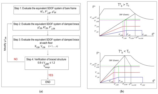
Figure 1.
DCP design method. (a) Flowchart; (b) equivalent bilinear curves.
Thus, according to the flow chart in Figure 1a, the first step in this procedure is to determine the mechanical characteristics of the equivalent SDOF system for the bare structure. Capacity curves for both main directions of the building are obtained using pushover analysis. The structure’s idealized elastoplastic force–displacement relationship is defined using the following parameters: the SDOF equivalent mass m* where mi is the story mass of MDOF, and is the eigenvector of the first mode in the relevant direction normalized with respect to the top-story component, and Γ1,BF ).
Thus, equivalent SDOF force F* and displacement d* parameters are obtained from the attendant values of the actual MDOF parameters by division for the first-mode transformation factor Γ1,BF, i.e., yield force (F*y = Vby/Γ1), yield displacement (d*y,BF = dy,BF/Γ1), and ultimate displacement d*u,BF = du,BF/Γ1, as detailed in Annex-B of [45]. The elastic stiffness (k*BF = F*y,BF/d*y,BF) or maximum ductility (μ*BF = d*u,BF/d*y,BF) are the same as the equivalent SDOF and actual MDOF.
Step 2 involves evaluating the properties of the equivalent SDOF system of the dissipative braced frame. An iterative procedure should be performed separately for each main direction. The dissipative braces (DB) system is idealized as an elastoplastic system defined by the yield force (FDB), elastic stiffness (kDB), and design ductility (μDB). Given a maximum target displacement d*max,DBF for the equivalent SDOF system of the braced frame DBF under the basic design earthquake (BDE), the target ductility μ*T,BF of the existing bare frame (BF) is defined by the following:
If the design goal for the structure is to remain elastic (μ∗T,BF = 1), then d*max,DBF must be less than or equal to d*y,BF. Otherwise, if a limited inelastic capacity is allowed, the target ductility (μ∗T,BF) can range from 1.5 to 3, depending on whether the mechanism is brittle or ductile, respectively. In this case, d*y,BF < d*max,DBF ≤ d*u,BF.
A design ductility μDB for the equivalent SDOF dissipative bracing system (DB) is assumed; optimal ductility values range from 4 to 12, depending on the properties of the hysteretic device and the serviceability design earthquake (SDE). Consequently, the yield displacement of the equivalent SDOF bracing system d*y,DB is calculated as given below:
At the j-th step of an iterative procedure, the equivalent period T*jDBF and the total elastic stiffness k*jDBF of the DBF structure are determined by means of the idealized elastoplastic behavior of the braced structure, using Equations (3a) and (3b).
where α = 1 is initially retained. The stiffness of the equivalent SDOF dissipative bracing system is obtained as the difference between the total stiffness and the frame stiffness , and the yield force of the dissipative braces is .
If in Equation (3a), T*jDBj< Tc is found, a new idealized bilinear curve must be evaluated on the basis of the force displacement curve obtained by the sum of the contribution of the actual bare frame and the properties of the dissipative braces at the j-th iteration, thus evaluating and the attendant value of the behavior factor at the j-th iteration as follows:
The iterative procedure starting from Equation (3a) with the updated value of α should be performed.
Once the characteristic parameters of the equivalent dissipative braces are evaluated, the actual dimensions and yielding force of the dissipative braces can be evaluated as previously described. It has to be remarked that the authors suggested applying an amplification factor γx = 1.2 on the yielding force of each dissipative braces to avoid either buckling or premature yielding under the maximum considered earthquake.
The proposed procedure suffers from (a) the conservative estimate of the displacements for systems with T* < Tc based on the equal energy criterion already reported by the authors; (b) the assumption of a further 20% increase in the resistance of the device (γx = 1.2 not taken into account in this work); (c) the initial assumption of a distribution of the stiffness and resistance characteristics of the dissipative braces proportional to that of the frame, providing for a correction only if the elevation regularity requirements of the Italian code [43], which are not satisfied, and such correction, which is desired to correct the elevation irregularities of structures not designed for seismic actions, should be provided already in the design phase of the bracing system; (d) an approximate evaluation of the resistance of the frame at each floor, evaluated based on the secant stiffness obtained in correspondence to an unspecified level of the external seismic action.
2.2. Bruschi, Quaglini, and Calvi Method (BQC) [22]
The main differences between this method [22] and the previous discussed procedure are that (i) the method for evaluation of the displacement demand is based on the equivalent damping, and the equivalent damping is evaluated on the basis of the hysteretic behavior of dissipative braces and existing bare frame, as defined in procedure 2 of the Italian Building Code [43], according to Shibata and Sozen [44]; (ii) the modal properties of the bare frame are used to evaluate the target displacement demand of the DBF by assuming a design pattern of the DBF displacements along the height of the frame that is proportional to the first modal shape of the bare frame and a target value of the maximum inter-story drift; and (iii) according to item (ii), the distribution of stiffness and resistance characteristics of the dissipative braces are proportional to those of the frame.
Regarding (i), the equivalent bilinearized SDOF system differs from the one described in the previous procedure by the following: the stiffness of the elastic branch, which is settled here as the initial elastic one rather than the secant value at 0.6 Vbmax, as in the previous procedure, and the shape of the second branch, which is characterized by a post-elastic stiffness KH > 0, evaluated together with the displacement demand d*max and the yielding force F*y on the basis of the following relationship:
where is the effective period evaluated on the basis of the effective stiffness, i.e., secant stiffness keff = F*u/d*max, and E*H is the energy absorbed (the area under the force–displacement curve) by the actual SDOF system up to the demand displacement. is a coefficient that reflects the energy dissipation capacity of the system, and it is settled , 0.66, and 0.33 for structures with high, medium, or low damping capability, respectively, with the latter depending on the stability of the hysteresis cycles. Equation (5c) is obtained by ensuring that the area under the equivalent bilinear curve is equal to E*H. An iterative procedure is used to find the equivalent damping value and the period of vibration T*, which are consistent with the displacement demand.
The main steps of this procedure can be summarized as shown in the flowchart in Figure 2a and in the acceleration displacement response spectrum ADRS in Figure 2b,c. The main capacity curve of the bare frame is evaluated using static nonlinear analysis, and the MDOF is converted into equivalent SDOF system, as described in the previous method. The target displacement of the system dmax is chosen according to the design performance that is required by the dissipative braces. The authors suggested to choose the target displacement in order to protect both structural and non-structural elements, corresponding to a maximum inter-story drift of the dissipative braced frame Δdi,max,DBF/hi in the range 0.5% ÷ 0.75%, with hi being the inter-story height of the i-th story. Thus, the target value of the top-story displacement of the DBF is evaluated as follows:
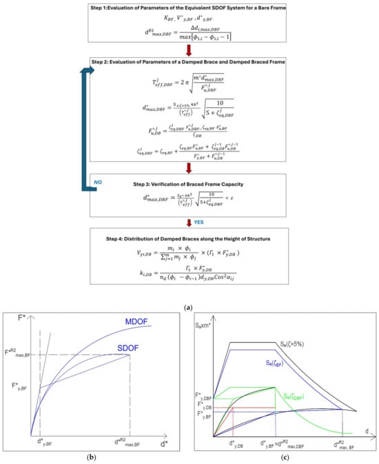
Figure 2.
BQC design method. (a) Flowchart; (b) equivalent bilinear curve; (c) design method representation in the ADRS. R2 is added to symbols to emphasize that the values of the parameters are evaluated according to procedure 2 of the Italian Building Code [43].
The target top-story displacement of the DBF is converted into the target displacement of the DBF equivalent SDOF, and the capacity curve of SDOF system is converted into the equivalent bilinear curve with hardening. Then, the characteristic parameters of the equivalent DB system are designed depending on the design value of the dissipative braces ductility μDB= and the equivalent damping of the damped brace *eq,DB = 63.7 (μDB − 1)/ μDB. The former can be chosen within the range 4 ≤ μDB ≤ 10, according to the dissipative device technology. Then, the equivalent viscous damping *eq,BDF, the yielding displacement , and the ultimate strength of the DBF SDOF equivalent system (i.e., the strength at the maximum displacement =, xx = BF,DB,DBF) are determined by the iterative procedure based on Equations (5)–(7d):
When the suitable damping and yield strength of the braced frame has been determined, the strength of the SDOF dissipative braces is obtained as . Thus, for each brace, the strength (Equation (8a)) and the stiffness (Equation (8b)) are determined as follows:
where nd is the number of braces at each story, and αij is the inclination of the j-th braces of the i-th story.
The BQC procedure is particularly efficient for regular bare frames, as it is able to take into account the high hysteretic capacities of the bracing systems equipped with dissipative devices through the evaluation of the equivalent damping. However, it leads to an oversizing of the braces due to the choice of designing the strengthened structure with the same modal shape as the bare frame. Thus, a highly precautionary design displacement of the braced structure is assumed when the bare frame is characterized by a marked irregularity in elevation (see Equation (6)); indeed, in this case, a value of , much larger than 1/np (where np is the number of the story), is found, with the latter being the value that characterizes the behavior of a structure designed to exhibit a constant inter-story drift.
2.3. Simplified Method (CAD)
A simplified method is derived to investigate the efficiency of procedures that aim to mitigate the effect of possible irregularity along the height of the bare frame. The main difference compared to the previous method, besides using elementary relationships that are easily understood by common practitioners, lies in the desire to obtain, for the braced structure, a constant inter-story drift along the height. Constant inter-story drift aims at obtaining uniform damage in the presence of earthquakes of unexpected intensity and at reducing the amount of material used for the braces.
According to the simplified procedure, characterized by a flowchart and with a representation in the ADRS shown in Figure 3a,b, respectively, once the total drift ΔΤ is chosen, the target eigenvector of the BDF structure is settled as , where zi is the height of the i-th story above the level of application of the seismic action, and HT is the total height of the frame.

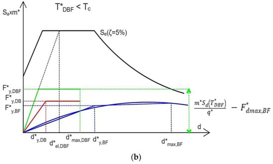
Figure 3.
Simplified (CAD) design method: (a) Flowchart; (b) ADRS representation.
The target displacement is evaluated as = ΔT HT, the mass of the equivalent SDOF as m*=, and the first-mode transformation factor as Γ1,DBF=. To evaluate the behavior of the bare frame, as it will be exhibited in the BDF, a pushover curve is evaluated by using a pattern of the seismic force, which is “triangular”, i.e., proportional to the product of mi × zi. Then, the design of the stiffness of the SDOF bracing system DB is performed on the basis of the modified equal displacement rule (EDR1) suggested by the [41] and the Italian Seismic Codes [43], namely = for or the amplified value , where , for . The value of the behavior factor should be chosen as to optimize the dynamic behavior and limit the variation in the axial force induced by the braces in the columns of the frame. To optimize the dynamic behavior, should be chosen within the range 3 ≤≤ 10 for (as suggested by [14], where recommended values are in the narrowest range 4 ≤ ), while in order to mitigate the expected increment of the displacement demand for should be adopted (according to [14], a limit recommended value is = 3). Thus, the design values of the period of vibration and the yielding strength of the SDOF DBF can be evaluated as follows:
Once the global parameters of the SDOF DBF are evaluated, the stiffness and the strength of the actual MDOF DB system at each story i can be easily evaluated on the basis of the lateral force method, taking into account that the stiffness and the strength of the DBF at each story are the sum of those of the DB and BF. The value of stiffness ki,BF should be evaluated in correspondence to the design value of the inter-story drift at the yielding displacement of the brace dyi,DB. Thus, the following expressions are obtained:
One iteration to evaluate Vyi,DB is required.
3. Case Study
To compare the effectiveness and the damage distribution obtained by designing the dissipative braces according to the three previously described methods, the seismic response of a four-story building was analyzed. The chosen building can be considered representative of the design and construction common practice of the 1970s in Southern European countries such as Italy, Portugal, and Greece. These structures were designed for vertical loads only, and they show very low resistance to horizontal loads in terms of ultimate limit state (in the order of approximately 5–8% of their weight).
The performance ensured by the three design methods was investigated by means of both static pushover analysis (POA) and dynamic nonlinear response history analysis (NRHA). POA was also used because it is well known that the results of NRHA are strongly influenced by the modeling of the seismic excitation. Moreover, since the results obtained by NRHA are highly scattered, a great deal of analysis should be performed in order to obtain a reliable statistic of the response, which can be reliably characterized by a probabilistic approach only. POA overcomes this issue, characterizing the seismic action by the elastic response spectrum. Thus, POA can be considered an efficient analysis method to compare design outcomes resulting from the application of different design methods, highlighting the specific characteristics of the designed structures, and the NRHA is a technique for investigating the effects of the features emerging from the POA on the dynamic and seismic behavior of the structures.
3.1. The Reinforced Concrete Moment Resistant Frame
A general view of the structure is provided in Figure 4. The building is a reinforced concrete 4-story frame with three bays in each of the two principal directions, namely two with a 5 m span and one with a 2.5 m span in the x-direction, and constant 5 m spans in the y-direction. The inter-story height is 2.7 m, and a 0.15 m thick slab extending 2 m on each side is cast together with the beams. Beams equal in terms of geometry and reinforcement are arranged on all floors. The columns, except for the wider interior one, present uniform geometric characteristics along the height of the structure. The columns feature a rectangular cross-section measuring 0.60 m × 0.25 m on the first and second stories and 0.50 m × 0.25 m on the third and fourth stories.
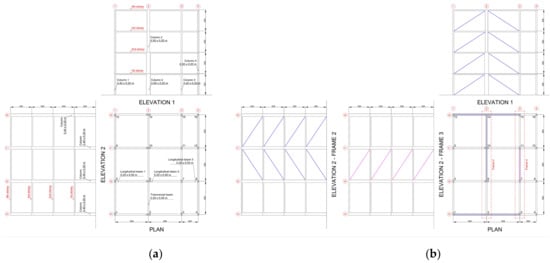
Figure 4.
Plan and section of (a) bare frames (BF) and (b) dissipative braced frames (DBFs).
Figure 4 also illustrates the geometric characteristics of the beams, while the reinforcement details are reported in Table 1. The reinforcement details of the building are coherent with the construction practice of the time: No seismic detailing provisions are considered, preferential mechanisms for inelastic dissipation are not assumed, and no specific ductility or strength provisions are assigned. Smooth, round bars, which were commonly used in the past, are used for the longitudinal reinforcing steel. All beams in the x-direction are 250 mm wide and 500 mm deep, while the transverse beams are 200 mm wide and 500 mm deep. The solid concrete slab has a thickness of 150 mm. The columns’ reinforcement splices and stirrups details reflect the typical lack of confinement seen in non-ductile reinforced concrete structures of 40 years ago. The longitudinal reinforcement of all four columns includes a lap splice (70 cm) at the base of the first story and another at the base of the third story. Consequently, at the base of the first story column, the reinforcement is duplicated, and at the base of the third story, there is an overlap of the nominal reinforcement with that from the lower story.

Table 1.
Details of cross-section of the main structural elements.
3.2. The Design of the Dissipative Braces
Dissipative braces are designed to withstand seismic action characterized by a type 1, ground-type B ζ = 5% damped elastic response spectrum [41] defined by the following parameters: peak ground acceleration ag = 0.35g (g = gravity acceleration), soil amplification factor S = 1.2, Tb = 0.15 s and Tc = 0.5 sec limits of the constant spectral acceleration branch, and Td = 2 s value defining the beginning of the constant displacement response range of the spectrum.
All three methods require that the mechanical characteristics of the bare frame and the parameters of the MDOF and equivalent SDOF system are estimated. With this aim, the pushover curves of the frame are evaluated for lateral force distribution consistent with the first-mode shape for negative x-direction (which provides the most conservative results with respect to the positive x-direction) and y-direction (either positive or negative since the system is symmetric in the y-direction). These curves are shown in Figure 5a,b, respectively. Then, according to the two previously mentioned procedures, namely elastic–perfectly plastic bilinearization + equal displacement rule procedure (denoted as EDR1 procedure) or elastic–plastic with hardening bilinearization + equivalent damping procedure (denoted as ED2 procedure), the parameters that characterize the bilinear curves are evaluated and reported in Table 2. The displacement demand as assessed by the two methods is also shown. Moreover, in Table 3, the results that characterize the behavior of each story are shown, with the latter evaluated in correspondence of the BF-yielding displacement estimated according to procedure EDR1.
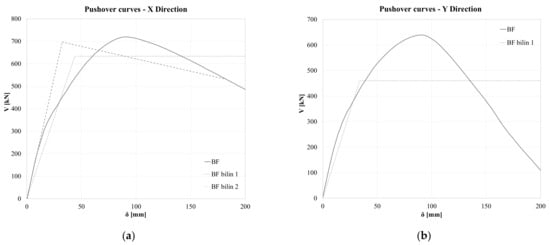
Figure 5.
Pushover curve of bare frame in the (a) x-direction and (b) y-direction.
Table 2.
Characteristics of the equivalent MDOF system of the bare frame according to the two different bilinearization procedures; j = EDR1, ED2; = equivalent stiffness; = ultimate secant stiffness; (n.a. = not applicable).
Table 3.
Main characteristics of each story of the bare frame. n.a. = not applicable.
Figure 5a,b show that the spatial frame has a slightly larger maximum strength in the x-direction (719 kN) than in the y-direction (639 kN), and a steep softening behavior in the y-direction characterizes the post-peak behavior, with no residual strength for the displacement of 220 mm. It is noteworthy that, from the data referring to the EDR1 method in Table 2, the structure has similar stiffnesses in the x- and y-directions (slightly larger in the x-direction) but different equivalent strengths (633 kN in the x-direction while only 460 kN in the y-direction) due to the steep softening behavior in the y-direction. Thus, EDR1 and ED2 assesses similar required displacements in the x-direction, namely 194 mm and 183 mm, while the ED2 method cannot be applied in the y-direction due to the lack of residual strength for displacements larger than 220 mm. The data in Table 3 highlight the abrupt reduction in the stiffness in the x-direction at the third story, while in the y-direction, a reduced value of the yielding displacement at the first story can be seen. Lastly, in Figure 6, the frame configurations at the displacement demand for the EDR1 method are shown. They stress that in the x-direction, a soft story mechanism at the third story is expected, while in the y-direction, the collapse mechanism involves great displacement at the first story.
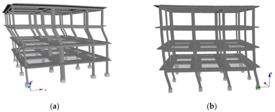
Figure 6.
Deformed view of bare frame under pushover analysis: the (a) x-direction and (b) y-direction.
The three above-mentioned design methods were applied, assuming a design inter-story drift ΔT = 0.5% corresponding to the damage limit state of the Italian Building Code [43], namely 16 mm. Thus, according to the assumption of constant inter-story drift that characterizes the DPC and CAD procedures, top-story displacement designs of 64 mm are assumed for both of them in both directions, while the 52 mm and 51 mm design for top-story displacements in the x- and y-directions, respectively, are assumed for the BQC procedure, according to Equation (6). Regarding the strength of dissipative braces, a design ductility of the braces of μDB = 4 is chosen for the DPC and the BQC method, as suggested by the authors in references [20,22], while a limit value of the behavior factor qlim = 3 for the CAD method is assumed [14]. The stiffness and strength global parameters at each story obtained with the three procedures are reported in Table 4. Regarding the in-plane distribution of the braces, reported in Figure 4b, it must be emphasized that in the x-direction, at each story, two couples of braces of the same dimensions and sliding force are designed in the wider bays of the external frames #5 and #6, arranged in order to minimize the variation in the axial force in the columns. In the y-direction, at each story, two braces are placed in the second and third bays of the frame #2, while one brace is placed in the second bay of the frame #3; the latter has a stiffness and strength equal to two-thirds of each of the previous ones in order to ensure that, on all the stories, the center of stiffness and resistance of the braces are coincident with the center of mass of the frame, and no torsional effect is induced. The required volume of the steel braces is similar for DPC and BQC methods, namely 0.622 m3 and 0.601 m3, while a volume roughly 40% smaller, namely 0.353 m3, is required for the CAD method.
Table 4.
Stiffness and sliding forces of the braces DB for the three design methods.
4. Results and Discussion
The structures were modeled by the Seismostruct FEM program [61]. Beam and column were modeled as inelastic force-based plastic hinge (INFRMFBPH) frame element type [62,63,64,65,66,67]. The Mander et al. [68] model for concrete and its modification for cyclic load [69] and Menegotto Pinto model [70], implemented as in Monti et al. [62] with the additional memory rule proposed by Fragiadakis et al. [63] for reinforcing steel, were used. The behavior of the dissipative braces was obtained by a simple truss model with a nonlinear link with stable elastic–perfectly plastic hysteresis cycle.
4.1. Pushover Analysis
In Figure 7a,b the pushover curves for the dissipative braced frames are depicted for the x- and negative y-direction, respectively, within the bilinear curves obtained with the EDR1 and ED2 methods. The points representing the yielding and the displacement demand and corresponding strengths are also depicted by the curves. In Table 5, all the numerical values are reported within the values of the equivalent stiffness for EDR1 method as well as the secant stiffness at the displacement demand for the ED2 method. The corresponding strength and period of vibration are also reported.
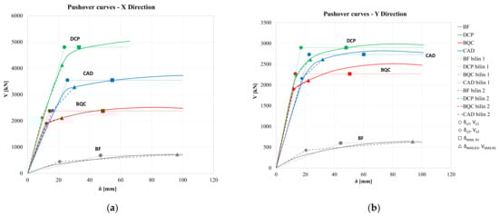
Figure 7.
Pushover curve of dissipative braced frames in the (a) x-direction and (b) y-direction.
Table 5.
Characteristics of the equivalent DBF-MDOF system for different design and bilinearization procedures.
Figure 7a,b and the results in Table 5 highlight that for all design methods, the DBF equivalent period of vibration in the EDR1 procedure is smaller than Tc. Comparison of the results with those reported in Table 2 for the BF was performed by assessing the ratio of DBF to the BF response parameter evaluated according the EDR1 procedure. The values of the stiffness ratio are 14.0 and 12.4 for DPC-DBF, 11.5 and 12.5 for BQC-DBF, and 9.6 and 8.9 for CAD-DBF in the x- and y-directions, respectively. The values of the strength ratio are 7.6 and 6.3 for DPC-DBF, 3.74 and 4.92 for BQC-DBF, and 5.6 and 5.9 for CAD-DBF in x- and y-directions, respectively. Displacement demand for the bare frame is always larger than 183 mm, and the values for the three DBF are within the range . Thus, it can be easily concluded that all the three methods provide efficient design of the dissipative bracing system, with large increments in stiffness and strength and large reduction in the expected damage.
DPC design method provides dissipative braces with the greater stiffness and strength among the three methods, although the assessed design displacement is greater than that of the BQC method. This is due to the over-conservative estimation of the increment of displacement for a stiff (T < Tc) nonlinear system with respect to an elastic one due to the assumption of the equal energy rule. The CAD method provides a lesser system stiffness, exploiting the assumption of the largest top-story displacement design; the use of a procedure based on the force method to establish the frame strength results in an intermediate strength between those provided by the DCP and BQC design methods. The EDR1 procedure assesses a larger displacement demand than ED2. An exception was found for the structure designed by the BQC method in the y-direction, having an average reduction in the assessed displacement of approximately 10%. Regarding the different design methods, averaging the displacement in x- and y- directions, the DPC method provides the smallest mean displacement value irrespective of the bilinearization procedure; the assessed displacement is 22% and 41% larger for the BQC and CAD methods, respectively, according to the EDR1 procedure, while it is 77% and 61% larger according to the ED2 procedure.
In order to compare the effect of the different distributions of stiffness and strength along the frame height assumed in the three design methods, in Figure 8, the inter-story drifts assessed by pushover analyses for the design total drift ΔT= 0.5%, namely a top-story displacement of 64 mm, are depicted.
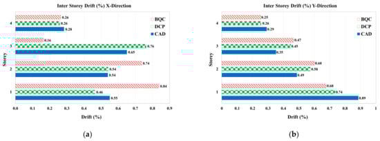
Figure 8.
Inter-story drift assessment for dissipative braced frames by pushover analysis in the (a) x-direction and (b) y-direction.
For all the three design methods and for both directions, the inter-story drifts at the upper story are small, with roughly 50% of the design inter-story drifts being ΔT= 0.5%. The drift distribution along the frame elevation provided by the BQC procedure, for which the braces are sized at each story with no one technique for bare frame irregularity correction, is the more non-uniform, with a larger drift at the first story for the x-direction, while it is reduced almost linearly along the structure height for the y-direction. The DPC and CAD method provide a more uniform distribution of the inter-story drifts along the elevation in the x-direction, while in the y-direction, the first-story drift is significantly larger than that expected. An almost linear reduction for the upper floors was also detected for these two methods in the y-direction.
The unexpected non-uniform distribution of the inter-story drifts obtained by the CAD method can be attributed to three main phenomena that are, in fact, neglected in all three considered design methods: (i) the variation in stiffness and strength (and ductility) of the frame columns due to the variation in the axial load generated by the braces; (ii) the influence of displacements due to axial deformations of the columns, which are not negligible in a structure with columns with reduced cross-sectional area; and (iii) the variation in the distribution of stiffness along the height compared to the design values, generated by the use of commercial profiles of the braces, which do not reflect the design areas.
In this context, an in-depth discussion of the role of the variation in axial forces in the columns due to the braces and the dissipative device strength calibration is beyond the scope of this paper. Nevertheless, to highlight the extent of this effect, in Table 6, the values of the axial loads at the base of the first-story columns, which are affected by the braces, are reported. Namely, the table reports the values of column axial loads due to gravitational load Ng, along with the minimum Nmin and the maximum Nmax values attained by pushover analysis in correspondence to maximum seismic force values (both in the positive and negative x- and y-directions). Referring to seismic action in the x-direction, in the bare frame, the columns affected by the largest variation in axial load are column 1 and column 3. The variations due to seismic actions with respect to the values for gravitational loads are roughly in the ranges [−50%, +27%] and [−50%, 0%], respectively. The introduction of dissipative braces significantly enlarges this variation, which ranges between [−177%, +258%] and [−218%, +266%] in column 1 and column 3, respectively, for the DPC design methods. The variation is slightly lower, in the ranges [−174%, +199%] and [−212%, +212%], in column 1 and column 3, respectively, for the BQC design methods.
Table 6.
Axial force values due to gravitational load (Ng) and extreme values due to gravitational + seismic forces in POA.
A similar behavior was found in the y-direction. In this case, for the bare frame, the largest variation was found for column 14, which shows a variation in the range [−39%, 18%], while for the braced frame, the variation in the same column is extremely large for the DPC and CAD design methods, namely [169%, +173%] and [−190%, +180%], respectively. For design of braces according to the BQC method, the variation is still large but slightly smaller and within the range [−146%, 134%]. Very significant variations were also found in column 11 for all the design methods.
The results clearly show the large variation in the axial force in columns induced by the braces and the paramount role played by the appropriate tuning of the dissipative device strength in limiting these variations.
4.2. Nonlinear Response History Analysis (NLRHA)
The reliability of the three design methods was also compared by nonlinear response history analysis. To this aim, initially, for each direction, three samples of quasi-stationary accelerograms were generated. They were characterized by a stationary energy content at the different frequencies but with amplitude modulated by a trapezoidal window function [71], according to the procedure described in [72]. Accelerograms that were compatible with the response spectrum described in the previous section were generated. In Figure 9, the response spectra of the samples and the mean spectrum are compared with the target spectrum. The curves show that the procedure provides accelerograms with a mean elastic response spectrum slightly larger than the target spectrum in the period range of constant spectral acceleration. The accelerograms fulfill the requirement than the mean spectrum is not less than 90% of the target spectrum for any period.
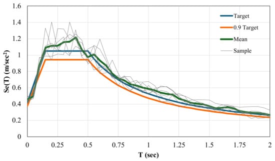
Figure 9.
Elastic response spectrum of the generated accelerograms vs. target spectrum.
The choice to use generated accelerograms instead of more realistic recorded accelerograms is aimed at minimizing the dispersion between the responses obtained by the NRHA for the different samples of seismic excitation, avoiding the uncertainties linked to the use of natural accelerograms with spectra very different from each other. In fact, only by using many samples of seismic excitation from recordings of real events, it is possible to obtain a reliable statistical description of the seismic response, which must be characterized by mean values, coefficients of variation, and extreme values. It should be noted that, in this context, the technique for selecting the accelerograms is still a subject under extensive debate, and no univocal guidelines have been identified.
Moreover, aiming at evaluating the effects of the bidirectional input on the seismic response of reinforced concrete frames retrofitted with dissipative braces, two set of analyses were performed: a first one with one-directional input only and a second set with bidirectional input.
Referring to the first set of analyses for one-directional input in the x- or y-direction, the mean and the maximum values of total and inter-story drift obtained by NLRHA are reported in Table 7 for both BF and DBF. Inter-story drift values are also represented graphically in Figure 10 for DBF only.
Table 7.
Mean and maximum total and inter-story drift in NLRHA for one-directional input in the x- or y-direction.
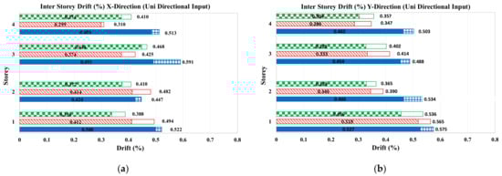
Figure 10.
Mean and maximum inter-story drift for NLRHA for one-directional input in the (a) x- direction (b) y-direction.
With reference to total drift, while for BF, the drift demand is larger than 1% in both the directions, when approaching the failure condition, the braces sized with all the design methods are successful in limiting the maximum value of the drift to 0.5%. The more conservative DCP method leads to designing very stiff and resistant bracing systems, resulting in a maximum total drift of 0.37% in both directions. Slightly larger values characterize the maximum total drift of DBF designed according to BQC method, namely 0.40% and 0.38% in the x- and y-directions, respectively. The CAD method led to the weakest dissipative braces, resulting in a maximum total drift close to the first design both in the x- and y-directions, namely 0.45% and 0.5%, respectively.
Notice that, as a consequence of the seismic excitation modeling, a relatively small difference between maximum and mean value of the response was found, which, for the DBF system, is on average equal to 9.1% of the mean value, with a maximum difference of 14% for the CAD frame in the y-direction.
Regarding the inter-story drift, all the methods were unsuccessful in limiting it at the first story for input in the y-direction, resulting in maximum values of 0.58% for CAD, 0.56% for BQC, and 0.54% for DCP. The CAD method was the only one unsuccessful in limiting the inter-story displacement in the x-direction, resulting in inter-story drift maximum values of 0.59% at the third story, 0.52% at the first story, and 0.51% at the fourth story.
In order to analyze the distribution of inter-story drift along the height of the frame, in Table 8, the mean values, coefficient of variation (COV), and minimum and maximum values of the inter-story drift among the four story are also evaluated. Referring to the values of drift obtained as a mean value of the response for the three accelerograms, the CAD method is able to ensure an almost uniform distribution of the drift along the height of the frame, with COV limited to 8% and 7% in the x- and y-directions, respectively. These values are significantly smaller than their counterparts for the other two design methods, namely 11% and 15% for DPC and 11% and 23% for BQC.
Table 8.
Mean and maximum total and inter-story drift in the x- or y-direction for NLRHA for bidirectional input.
Referring to the values of drift obtained as the maximum value of the response for the three accelerograms, the same trend was found, with the exception of DCP methods in the x-direction, which is able to ensure the most uniform inter-story drift distribution characterized by the smallest COV = 8%. It must be emphasized that such results are obtained with a similar material usage for DPC and BQC methods and a volume 40% smaller for the CAD method.
It is noteworthy that, in the context of NLRHA, most of the international seismic codes require that a bidirectional seismic excitation is applied to the structure [41], with the two-time history in the x- and y-directions to be non-correlated. In this context, the debate on the methods of selecting natural accelerograms [46] and generating artificial ones is still open.
Then, the bare frame and the three previously designed frames were analyzed by NLRHA with bidirectional input, modeled by generating, by the same method previously described, three other samples of the input, each of which was used to model the second component of the input acting simultaneously with those previously used for monodirectional input.
The values of the mean and the maximum total and inter-story drift in the x- and y-directions obtained by NLRHA for bidirectional input are reported in Table 8. For the bracing systems, inter-story drifts are also represented graphically in Figure 11.
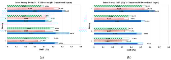
Figure 11.
Mean and maximum inter-story drift for NLRHA bidirectional input (a) x- direction (b) y-direction.
It is noteworthy that for bidirectional input, for the bare frame, both the total and all the inter-story drift in the x-direction overcame the 3% that is conventionally assumed as an overestimated failure drift. In the y-direction, the values approached (and sometime overcame also) the 2% that is a more realistic estimation of the failure drift for a non-earthquake-resistant frame design. Therefore, the results highlight that the BF is not able to cope with the seismic action thus modeled.
Regarding the behavior of the DBF, for all the design methods, the mean total drift was always smaller than the design one (0.5%). However, none of the methods were able to ensure an inter-story drift smaller than that of the design in the y-direction at the fourth story, and an exceedance of the limit was also found at the first story in the x-direction for both the BQC and CAD methods.
The comparison with the values for monodirectional input shows that for the bare frame, the effects of the bidirectional input are extremely relevant since the structure is loaded in conditions close to collapse even for unidirectional input, and a slightly more demanding seismic action is able to cause its collapse. For the DBF, the total and inter-story drift averages for the three design methods and the two response directions are only slightly increased with respect to the ones for the one-directional input. Variations of roughly 3.9% for the mean values, 3.0% for the total drift maximum values, and 5.5% and 4.5% larger for the mean (among the stories) inter-story drift and mean and maximum values (among the three accelerograms) were obtained. The largest variation was found for the CAD design method and the x-direction of the response.
5. Effect of Repeated Seismic Action
In the updated application of seismic strengthening, great importance is now given to the evaluation of the effects of repeated seismic actions, which have already been highlighted in the past by several researchers [36,37,38], both with reference to the effects of damage in determining the behavior of the structure related to a seismic action of intensity comparable to that previously suffered (design earthquake) and in producing an accumulation of damage. Recently, this issue returned to favor [73] in life cycle assessment [74] and assessing the resilience of structures [75,76]. None of the methods analyzed consider this aspect in defining the characteristics of the dissipative bracing system. By contrast, past [77,78] and recent [79,80,81] studies have demonstrated that self-centering braces have the ability to foster structural resilience by decreasing residual drift, accumulating damages induced by major earthquakes and repeated events.
With the aim of highlighting the paramount role that this aspect must play in the design techniques of dissipative bracing systems, in this section, the effect of a second seismic event of intensity and characteristics equal to the first on the behavior of the analyzed structure is evaluated. To model this effect, at the end of the first event, whose total duration was t = 35 s, a time interval of Δt = 5 s was considered, during which the system was not forced, and the oscillations caused by the first event were exhausted. At 40 s, the former event with 35 s time duration was applied again, with a direction opposite that of the former. This choice was motivated by the desire to avoid the effects of the residual drift at the end of the first event being unrealistically amplified by the second event.
In Figure 12a–h, the total drift in the x- and y-directions for the BF and the three DBF are reported for one sample for each direction of the seismic action. In Table 9, the increment of the maximum drift caused by the repeated seismic action with respect to the maximum value obtained by the correspondent single accelerograms is reported both for the total and the inter-story drift.
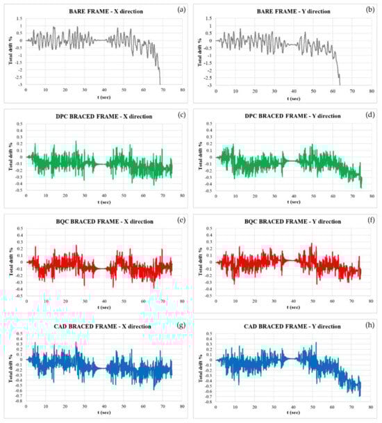
Figure 12.
Effects of the repeated seismic action on total drift of bare and braced frames in x and y direction; (a,b) bare frame, (c,d) DPC braced frame, (e,f) BQC braced frame, (g,h) CAD braced frame.
Table 9.
Increment of total and story drift (%) due to repeated seismic action.
Figure 12a,b show that, for the BF, the effect of the repeated action of the earthquake is tragic. The damage accumulated during the first event makes the structure unable to cope with the action of the second event, and after 20 s from the beginning of the second event, namely for t > 60 s, the structure breaks, with drift >3%, both when the earthquake has x- and y-direction. The results in Table 9 prove that the columns of almost all the stories undergo failure.
By contrast, the response of DBFs depicted in Figure 12c–h show that, thanks to the stability of the hysteresis cycles of the dissipative devices, the DBBs are able to contain the response to repeated action within sufficiently low drift values. Only the DBF designed with the CAD method exceeded the design total drift, reaching 0.59% due to an increase of 0.14% in the x-direction and a total drift of 0.7% due to an increase of 0.22% in the y-direction. The same increase of 0.15% recorded in the y-direction for the DPC does not cause the exceeding of the limit threshold of 0.5% since the displacement due to the first seismic event in this case was only 0.32%.
The analysis of the inter-story drift increases shown in Table 8 highlights a strong undesired increase in the drift at the first story for the DBF designed with the CAD method (+0.64%), which for the earthquake in the y-direction reaches 1.14%, highlighting a condition of potential failure. For this method, drifts of the third and fourth stories also reach 0.87% and 0.62%, respectively, for earthquakes in the x-direction.
The increases observed in the DBFs designed with the DPC and CAD methods are small and were found to exceed the design inter-story drift only at the third story for the DPC method and input in the x-direction (inter-story drift = 0.67%) and at the first story for the BQC design method and input in the y-direction (inter-story drift = 0.60%).
The results shown above highlight that, as is well known, RC frames without anti-seismic construction details are strongly prone to repeated seismic actions. The use of dissipative braces allows protection of the structure from the effect of repeated seismic actions. A careful analysis of the time histories in Figure 12a–h highlights that the increases in damage in DBFs are generated by the residual drift that occurs after a seismic event or even just a segment of the accelerogram of high amplitude. Many studies in the literature have highlighted that this effect can be mitigated, if not eliminated, by using dissipative re-centering braces [22,77,79,80,81]. Lastly, it must be remarked that the chosen input model, consisting of accelerograms generated as samples of a stationary process in amplitude and frequency in the strong-motion phase lasting 25 s, tend to overestimate the energy transmitted to the structure compared to that of a real event. This effect is particularly relevant if the response to two successive seismic events of the same intensity is evaluated.
Finally, considering the possible extension of these results in a broader context, it is worth noting that studies concerning seismic retrofit techniques of existing structures cannot ignore the characteristics of the structure to be retrofitted. The structure examined here can effectively represent the characteristics of a large number of structures built in the 1970s throughout a significant part of Southern Europe, the area of North Africa and South America, and probably in a wider geographical area. Moreover, the structure was chosen so that, once the intervention was carried out, the strengthened structure could be classified as a rigid structure with a vibration period lower than that of the end of the constant pseudo-acceleration branch in the response spectrum. For these structures, the analyzed design methods provided different indications on the estimate of the maximum expected displacement and therefore different design outcomes. The findings may not be directly applicable to other types of buildings or regions with different construction practices and seismic demands.
6. Conclusions
Three design methods were analyzed for the seismic strengthening design of reinforced concrete frames using braces equipped with dissipative devices. The comparison of the performances was performed by the strengthening of a spatial frame structure with typical characteristics representative of the design and construction common practice of the 1970s in Southern European countries. The chosen methods are characterized by different approaches for two key points of the design process: (i) procedures for estimating the peak displacement response of the nonlinear systems, namely the well-known equal displacement rule and the equivalent (secant) stiffness and damping rule, and (ii) the distribution of stiffness and resistance in elevation and in plan, namely stiffness and resistance distribution proportional to the characteristics of the structure to be strengthened or stiffness and resistance distribution in such a way as to correct the irregularities in plan and in elevation present in the structure.
The performance of the three braced frames was compared by means of POA and NLRHA. The results allow us to draw the following conclusions:
- The two different procedures of bilinearization and displacement estimation applied to rigid systems (T < Tc), even through different mechanical and dynamic parameters, led to predicted displacements similar to each other. However, when they were applied to systems with dissipative braces characterized by parameters that account for the energy dissipation capacity of the structure = 1, the ED2 procedure, based on the equivalent damping, provided a smaller assessment of the displacement demand than the EDR1 procedure, based on modification of the “equal displacement rule” for stiff systems;
- All the three dissipative braces-design methods allowed obtaining an efficient design of the dissipative braces that was able to avoid significative damage on the frame to be strengthened. Increases in the stiffness by about 10 times and in the strength between 7.5 to 3.7 times depending on the design method and reductions in the displacements in a range between 31% and 42% compared to the values of the original frame were found;
- The DCP method, when it leads to designing a rigid braced system (TDBF < Tc), was found particularly conservative due to the over-conservative assessment of the displacement demand for structures with T < Tc based on the equal energy rule;
- The CAD method can lead to an unconservative design of the dissipative braces since it is aimed at obtaining systems with the minimum possible stiffness because of the choice of a constant inter-story drift equal to the design maximum value. The effect of repeated seismic action stresses these circumstances. However, a gain in the used material of roughly 40% with respect to the other method highlights that the method has strong potential but requires improvement to be able to account for the effects of bidirectional inputs and repeated seismic events;
- The BQC method provides a reasonable solution based on the choice of limiting the inter-story displacement of the weakest floor to the maximum design value. However, it can produce an over-sizing of the braces on all the other floors. The method is not suitable for effective application to structures with high irregularity in elevation, where oversizing could be particularly relevant;
- In this regard, both the DCP and CAD methods try to regularize the structure: the DCP method ensures that the floor stiffness of the braced structure satisfies the limits of regularity in elevation of the Italian Regulatory Code [43] by containing the variations in stiffness and resistance within pre-established limits. The CAD method sizes the braces in relation to the stiffness of the structure to be reinforced so as to obtain constant inter-floor displacements for the braced structure. The effectiveness of these choices was demonstrated by the significant reduction in COV of inter-story drift guaranteed by the two structures;
- The variation in stiffness along the height, together with the realistic estimate of the maximum expected displacement, allows the CAD method to reduce the material used for the braces by about 40% compared to the other two methods. In terms of cost, it should be noted that the material is only a part of the overall cost of the seismic strengthening intervention;
- All the methods considered do not take into account the effects of the variation in the axial stress generated by the braces on the stiffness, resistance, and ductility of the columns of the reinforced concrete frame, which can be particularly relevant for undersized columns and in the case of reduced transverse confining reinforcements. This circumstance can make the behavior of the lower floors, whose columns are affected by the maximum variation in the normal stress, not always easy to predict.
Based on the results obtained, it can be concluded that the BQC method is the most effective for structures that, when strengthened with dissipative braces, present a vibration period included into the pseudo-constant acceleration branch of the spectrum, provided that the structures to be adjusted do not present significant irregularities in plan and height. This superior performance is guaranteed in the face of a 40% increase in the material used for the braces compared to the CAD method but with a lower increase in axial actions on the columns.
In the presence of large irregularities in elevation in the structure to be strengthened, the CAD method is to be preferred since, in addition to being based on simple relationships and allowing a reduction in the material usage for the braces, it is aimed at eliminating or mitigating such irregularities. However, it should be noted that these considerations cannot be considered general since they were verified on a single case study.
Finally, it should be noted that the definition of complete criteria and methods for the design of seismic retrofitting interventions using dissipative braces requires further studies and in-depth analyses. In this context, the following topics are considered to be of primary importance but do not constitute an exhaustive list: (i) study of the influence of the displacement demand assessment technique adopted on the global stiffness and resistance of the dissipative bracing system, in which particular emphasis should be placed on strengthened structures that have a vibration period lower than that of the end of the branch of the response spectrum at constant pseudo-accelerations; (ii) calibration of the global resistance of the bracing system, which must be aimed at identifying the lower limit threshold capable of ensuring the reduction in the design displacement and minimizing the variation in the axial force in the columns (limiting the increase in compression and avoiding the risk of generating tensile actions in the columns); (iii) definition of the laws of variation in stiffness and resistance of the braces along the height of the structure, reducing or eliminating the irregularities in elevation, which may better allow the structure to be strengthened; (iv) definition of clear criteria for the in-plan placement of the braces, which, respecting the architectural requirements, can mitigate the in-plan irregularities that may be present in the structure to be analyzed; the optimal placement should aim at reducing the variations in the axial force in the columns in relation to the different capacities of axial resistance and plastic deformation of the columns and also in relation to the capacity of the foundations to cope with such variations in the actions transmitted by the columns; and (v) investigation of the effect of repeated seismic action, residual drift and damage accumulation, and equipment of dissipative braces with self-centering devices.
Author Contributions
Conceptualization, Data curation, Formal analysis, Investigation, Methodology, Visualization, Writing original draft, Writing review & editing, M.A., P.C. and J.D.; funding acquisition, P.C. All authors have read and agreed to the published version of the manuscript.
Funding
The studies presented here were carried out as part of the activities envisaged by the RETURN Extended Partnership and received funding from the European Union Next-Generation EU (National Recovery and Resilience Plan—NRRP, Mission 4, Component 2, Investment 1.3—D.D. 1243 2 August 2022, PE0000005).
Data Availability Statement
The data presented in this study are available on request from the corresponding author.
Conflicts of Interest
The authors declare no conflicts of interest.
Abbreviations
Following Notations are used in this paper:
| xxx = (DBF = dissipative braced frame; BF = bare frame; DB = dissipative braces) | |
| d*el | Displacement demand of elastic SDOF |
| d*y,xxx | Yield displacement of SDOF xxx structure |
| dy,xxx | Yield displacement of MDOF xxx structure |
| d*u,xxx | Ultimate displacement of SDOF xxx structure |
| du,xxx | Ultimate displacement of MDOF xxx structure |
| d*max | Displacement demand of nonlinear SDOF |
| d*max, xxx | Displacement demand for the equivalent SDOF of the xxx |
| dR2max, xxx | Displacement demand for the MDOF xxx evaluated according the equivalent damping (ED2) procedure (procedure 2 of the Italian Building Code [35]) |
| T | Fundamental period of vibration of MDOF system |
| T* | Period of vibration of SDOF system |
| Tb, Tc | starting and the ending abscissa of the flat branch of the pseudo-acceleration response spectrum |
| T*eff,xxx, | Effective fundamental period of vibration of the xxx structure |
| m* | Mass of equivalent SDOF system |
| Eigenvector of the first mode of the MDOF system | |
| Γ1,BF | First-mode transformation factor |
| Fy,xxx | Yield force of MDOF xxx |
| F*y,xxx | Yield force of SDOF xxx |
| F*u,xxx = F*dmax,xxx | Ultimate strength of the xxx SDOF system |
| Ki,xxx | i-th story stiffness of the MDOF xxx structure |
| k*,xxx | Elastic stiffness of SDOF xxx |
| k* | Post-yielding stiffness of SDOF system |
| μBF* | Maximum ductility of equivalent SDOF bare frame |
| μDB | Design ductility of dissipative bracing system |
| μ*T,BF | Target ductility of the bare frame |
| T* jDBF | Equivalent period of the SDOF DBF at the j-th design iteration |
| k*jDBF | Total elastic stiffness of the SDOF DBF at the j-th design iteration. |
| Vbmax | Maximum base shear of MDOF system |
| Vb,y | Yielding base shear of MDOF system |
| E*H | Energy absorbed (area under the force–displacement curve) by SDOF system |
| Coefficient representing energy dissipation capacity of the system | |
| Equivalent damping ratio of the linearized system | |
| nd | Number of the braces at each story |
| np | Number of story |
| HT | Total height of the frame |
| Δdi | Inter-story displacement at the i-th story |
| ΔT | Total drift |
References
- Gkournelos, P.D.; Triantafillou, T.C.; Bournas, D.A. Seismic Upgrading of Existing Reinforced Concrete Buildings: A State-of-the-Art Review. Eng. Struct. 2021, 240, 112273. [Google Scholar] [CrossRef]
- Calvi, G.M. Choices and Criteria for Seismic Strengthening. J. Earthq. Eng. 2013, 17, 769–802. [Google Scholar] [CrossRef]
- Golias, E.; Schlüter, F.-H.; Spyridis, P. Strengthening of Reinforced Concrete Beam-Column Joints by Means of Fastened C-FRP Ropes. Structures 2024, 66, 106811. [Google Scholar] [CrossRef]
- Ebanesar, A.; Gladston, H.; Noroozinejad Farsangi, E.; Sharma, S.V. Strengthening of RC Beam-Column Joints Using Steel Plate with Shear Connectors: Experimental Investigation. Structures 2022, 35, 1138–1150. [Google Scholar] [CrossRef]
- Pohoryles, D.A.; Melo, J.; Rossetto, T.; Varum, H.; Bisby, L. Seismic Retrofit Schemes with FRP for Deficient RC Beam-Column Joints: State-of-the-Art Review. J. Compos. Constr. 2019, 23, 3119001. [Google Scholar] [CrossRef]
- De Lorenzis, L.; Teng, J.G. Near-Surface Mounted FRP Reinforcement: An Emerging Technique for Strengthening Structures. Compos. Part B Eng. 2007, 38, 119–143. [Google Scholar] [CrossRef]
- Colajanni, P.; Recupero, A.; Spinella, N. Increasing the Shear Capacity of Reinforced Concrete Beams Using Pretensioned Stainless Steel Ribbons. Struct. Concr. 2017, 18, 444–453. [Google Scholar] [CrossRef]
- Colajanni, P.; La Mendola, L.; Recupero, A.; Spinella, N. Stress Field Model for Strengthening of Shear-Flexure Critical RC Beams. J. Compos. Constr. 2017, 21, 4017039. [Google Scholar] [CrossRef]
- Monti, G.; Liotta, M. Tests and Design Equations for FRP-Strengthening in Shear. Constr. Build. Mater. 2007, 21, 799–809. [Google Scholar] [CrossRef]
- Koutas, L.N.; Tetta, Z.; Bournas, D.A.; Triantafillou, T.C. Strengthening of Concrete Structures with Textile Reinforced Mortars: State-of-the-Art Review. J. Compos. Constr. 2019, 23, 3118001. [Google Scholar] [CrossRef]
- Rocca, S.; Galati, N.; Nanni, A. Review of Design Guidelines for FRP Confinement of Reinforced Concrete Columns of Noncircular Cross Sections. J. Compos. Constr. 2008, 12, 80–92. [Google Scholar] [CrossRef]
- Raza, S.; Khan, M.K.I.; Menegon, S.J.; Tsang, H.-H.; Wilson, J.L. Strengthening and Repair of Reinforced Concrete Columns by Jacketing: State-of-the-Art Review. Sustainability 2019, 11, 3208. [Google Scholar] [CrossRef]
- Koutas, L.; Bousias, S.N.; Triantafillou, T.C. Seismic Strengthening of Masonry-Infilled RC Frames with TRM: Experimental Study. J. Compos. Constr. 2015, 19, 4014048. [Google Scholar] [CrossRef]
- Colajanni, P.; Papia, M. Hysteretic Behavior Characterization of Friction-Damped Braced Frames. J. Struct. Eng. 1997, 123, 1020–1028. [Google Scholar] [CrossRef]
- Wakabayashi, M. Behaviour of Braces and Braced Frames under Earthquake Loading. Int. J. Struct. 1982, 2, 49–70. [Google Scholar]
- Akiyama, H. Earthquake-Resistant Limit-State Design for Buildings; University of Tokyo Press: Tokyo, Japan, 1985; ISBN 4-13-068111-7. [Google Scholar]
- Maison, B.F.; Popov, E.P. Cyclic Response Prediction for Braced Steel Frames. J. Struct. Div. 1980, 106, 1401–1416. [Google Scholar] [CrossRef]
- Colajanni, P.; Recupero, A.; Spinella, N. Shear Strength Degradation Due to Flexural Ductility Demand in Circular RC Columns. Bull. Earthq. Eng. 2015, 13, 1795–1807. [Google Scholar] [CrossRef]
- Mazza, F.; Vulcano, A. Displacement-Based Design Procedure of Damped Braces for the Seismic Retrofitting of rc Framed Buildings. Bull. Earthq. Eng. 2015, 13, 2121–2143. [Google Scholar] [CrossRef]
- Di Cesare, A.; Ponzo, F.C. Seismic Retrofit of Reinforced Concrete Frame Buildings with Hysteretic Bracing Systems: Design Procedure and Behaviour Factor. Shock. Vib. 2017, 2017, 2639361. [Google Scholar] [CrossRef]
- Ferraioli, M.; Lavino, A. A Displacement-Based Design Method for Seismic Retrofit of RC Buildings Using Dissipative Braces. Math. Probl. Eng. 2018, 2018, 5364564. [Google Scholar] [CrossRef]
- Bruschi, E.; Quaglini, V.; Calvi, P.M. A Simplified Design Procedure for Seismic Upgrade of Frame Structures Equipped with Hysteretic Dampers. Eng. Struct. 2022, 251, 113504. [Google Scholar] [CrossRef]
- Benfratello, S.; Palizzolo, L.; Vazzano, S. A New Design Problem in the Formulation of a Special Moment Resisting Connection Device for Preventing Local Buckling. Appl. Sci. 2021, 12, 202. [Google Scholar] [CrossRef]
- Benfratello, S.; Caddemi, S.; Palizzolo, L.; Pantò, B.; Rapicavoli, D.; Vazzano, S. Targeted Steel Frames by Means of Innovative Moment Resisting Connections. J. Constr. Steel Res. 2021, 183, 106695. [Google Scholar] [CrossRef]
- Colajanni, P.; La Mendola, L.; Monaco, A.; Pagnotta, S. Seismic Performance of Earthquake-Resilient RC Frames Made with HSTC Beams and Friction Damper Devices. J. Earthq. Eng. 2022, 26, 7787–7813. [Google Scholar] [CrossRef]
- Pagnotta, S.; Ahmed, M.; Colajanni, P. Experimental and Finite Element Analysis of the Cyclic Behaviour of Linear Dissipative Devices. In COMPDYN Proceedings; National Technical University of Athens: Athens, Greece, 2023. [Google Scholar]
- Pall, A.S.; Verganelakis, V.; Marsh, C. Friction dampers for seismic control of concordia university library building. In Proceedings of the Fifth Canadian Conference on Earthquake Engineering, Ottawa, ON, Canada, 6–9 July 1987; pp. 191–200. [Google Scholar]
- Martinez-Romero, E. Experiences on the Use of Supplementary Energy Dissipators on Building Structures. Earthq. Spectra 1993, 9, 581–625. [Google Scholar] [CrossRef]
- Titirla, M.D. A State-of-the-Art Review of Passive Energy Dissipation Systems in Steel Braces. Buildings 2023, 13, 851. [Google Scholar] [CrossRef]
- Yoo, J.-H.; Lehman, D.E.; Roeder, C.W. Influence of Connection Design Parameters on the Seismic Performance of Braced Frames. J. Constr. Steel Res. 2008, 64, 607–623. [Google Scholar] [CrossRef]
- Valente, M.; Milani, G. Alternative Retrofitting Strategies to Prevent the Failure of an Under-Designed Reinforced Concrete Frame. Eng. Fail. Anal. 2018, 89, 271–285. [Google Scholar] [CrossRef]
- Filiatrault, A.; Cherry, S. Seismic Design Spectra for Friction-Damped Structures. J. Struct. Eng. 1990, 116, 1334–1355. [Google Scholar] [CrossRef]
- Ciampi, V.; De Angelis, M.; Paolacci, F. Design of Yielding or Friction-Based Dissipative Bracings for Seismic Protection of Buildings. Eng. Struct. 1995, 17, 381–391. [Google Scholar] [CrossRef]
- Ciampi, V. Development of passive energy dissipation techniques for buildings. In Proceedings of the International Post-SMIRT Conference Seminar on Isolation, Energy Dissipation and Control of Vibrations of Structures, Capri, Italy, 23–25 August 1993; pp. 495–510. [Google Scholar]
- Constantinou, M.C.; Soong, T.T.; Dargush, G.F. Passive Energy Dissipation Systems for Structural Design and Retrofit, MCEER Monograph No.1; Multidisciplinary Center for Earthquake Engineering Research: Buffalo, NY, USA, 1998. [Google Scholar]
- Elnashai, A.S.; Bommer, J.J.; Martinez-Pereira, A. Engineering Implications of Strong-Motion Records from Recent Earthquakes. In Proceedings of the 11th European Conference on Earthquake Engineering, Paris, France, 6–11 September 1998. CD-ROM. [Google Scholar]
- Amadio, C.; Fragiacomo, M.; Rajgelj, S. The Effects of Repeated Earthquake Ground Motions on the Non-linear Response of SDOF Systems. Earthq. Engng Struct. Dyn. 2003, 32, 291–308. [Google Scholar] [CrossRef]
- Hatzigeorgiou, G.D.; Liolios, A.A. Nonlinear Behaviour of RC Frames under Repeated Strong Ground Motions. Soil. Dyn. Earthq. Eng. 2010, 30, 1010–1025. [Google Scholar] [CrossRef]
- Elettore, E.; Francavilla, A.B.; Freddi, F.; Latour, M.; Rizzano, G. Preliminary numerical study of a steel concentrically braced frame equipped with dissipative braces and self-centring column bases. In Proceedings of the 11th International Conference on Behaviour of Steel Structures in Seismic Areas, Salerno, Italy, 8–18 July 2024; Mazzolani, F.M., Piluso, V., Nastri, E., Formisano, A., Eds.; Lecture Notes in Civil Engineering. Springer Nature Switzerland: Cham, Switzerland, 2024; Volume 520, pp. 418–430, ISBN 978-3-031-62887-0. [Google Scholar]
- Bergami, A.V.; Nuti, C. A Design Procedure of Dissipative Braces for Seismic Upgrading Structures. Earthq. Struct. 2013, 4, 85–108. [Google Scholar] [CrossRef]
- EN 1998–1 Eurocode 8; Design of Structures for Earthquake Resistance—Part 1: General Rules, Seismic Actions and Rules for Building. CEN (European Committee for Standardization): Brussels, Belgium, 2005.
- EN 1998–3 Eurocode 8; Design of Structures for Earthquake Resistance—Part 3: Assessment and Retrofitting of Buildings. CEN (European Committee for Standardization): Brussels, Belgium, 2005.
- CSLLPP (Consiglio Superiore dei Lavori Pubblici). Circolare 21 Gennaio 2019, n. 7 C.S.LL.PP. Istruzioni per L’applicazione Dell’«Aggiornamento Delle “Norme Tecniche per Le Costruzioni”» Di Cui al Decreto Ministeriale 17 Gennaio 2018, Roma; CSLLPP (Consiglio Superiore dei Lavori Pubblici): Roma, Italy, 2019. (In Italian) [Google Scholar]
- Shibata, A.; Sozen, M.A. Substitute-Structure Method for Seismic Design in R/C. J. Struct. Div. 1976, 102, 1–18. [Google Scholar] [CrossRef]
- Elishakoff, I.; Colajanni, P. Stochastic Linearization Critically Re-Examined. Chaos Solitons Fractals 1997, 8, 1957–1972. [Google Scholar] [CrossRef]
- Baraschino, R.; Baltzopoulos, G.; Iervolino, I. Reconciling Eurocode 8 Part 1 and Part 2 Two-Component Record Selection. J. Earthq. Eng. 2022, 26, 6918–6942. [Google Scholar] [CrossRef]
- Mazza, F. Nonlinear Seismic Analysis of r.c. Framed Buildings with Setbacks Retrofitted by Damped Braces. Eng. Struct. 2016, 126, 559–570. [Google Scholar] [CrossRef]
- Palermo, M.; Laghi, V.; Gasparini, G.; Silvestri, S.; Trombetti, T. A Multi-Performance Seismic Design Procedure to Incorporate Crescent Shaped Braces in Mid-Rise Frame Structures. Soil Dyn. Earthq. Eng. 2023, 164, 107625. [Google Scholar] [CrossRef]
- Kim, J.; Choi, H. Displacement-Based Design of Supplemental Dampers for Seismic Retrofit of a Framed Structure. J. Struct. Eng. 2006, 132, 873–883. [Google Scholar] [CrossRef]
- Lin, Y.Y.; Tsai, M.H.; Hwang, J.S.; Chang, K.C. Direct Displacement-Based Design for Building with Passive Energy Dissipation Systems. Eng. Struct. 2003, 25, 25–37. [Google Scholar] [CrossRef]
- Mazza, F.; Vulcano, A. Equivalent Viscous Damping for Displacement-Based Seismic Design of Hysteretic Damped Braces for Retrofitting Framed Buildings. Bull. Earthq. Eng. 2014, 12, 2797–2819. [Google Scholar] [CrossRef]
- Segovia, V.A.; Ruiz, S.E. Direct Displacement-Based Design for Buildings with Hysteretic Dampers, Using Best Combinations of Stiffness and Strength Ratios. J. Earthq. Eng. 2017, 21, 752–775. [Google Scholar] [CrossRef]
- Priestley, M.J.N. Myths and Fallacies in Earthquake Engineering. BNZSEE 1993, 26, 329–341. [Google Scholar] [CrossRef]
- Priestley, M.J.N. Performance Based Seismic Design. BNZSEE 2000, 33, 325–346. [Google Scholar] [CrossRef]
- Maley, T.J.; Sullivan, T.J.; Corte, G.D. Development of a Displacement-Based Design Method for Steel Dual Systems with Buckling-Restrained Braces and Moment-Resisting Frames. J. Earthq. Eng. 2010, 14, 106–140. [Google Scholar] [CrossRef]
- Sutcu, F.; Takeuchi, T.; Matsui, R. Seismic Retrofit Design Method for RC Buildings Using Buckling-Restrained Braces and Steel Frames. J. Constr. Steel Res. 2014, 101, 304–313. [Google Scholar] [CrossRef]
- Moradpour, S.; Dehestani, M. Optimal DDBD Procedure for Designing Steel Structures with Nonlinear Fluid Viscous Dampers. Structures 2019, 22, 154–174. [Google Scholar] [CrossRef]
- Noruzvand, M.; Mohebbi, M.; Shakeri, K. An Improvement of Direct Displacement-Based Design Approach for Steel Moment-Resisting Frames Controlled by Fluid Viscous Dampers. Adv. Struct. Eng. 2021, 24, 2148–2160. [Google Scholar] [CrossRef]
- Barbagallo, F.; Bosco, M.; Marino, E.M.; Rossi, P.P.; Stramondo, P.R. A Multi-performance Design Method for Seismic Upgrading of Existing RC Frames by BRBs. Earthq. Eng. Struct. Dyn. 2017, 46, 1099–1119. [Google Scholar] [CrossRef]
- Monti, G.; Rahmat Rabi, R.; Vailati, M. Direct Displacement-Based Design of Dissipative Bracings for Seismic Retrofit of Reinforced Concrete Buildings. J. Build. Eng. 2024, 82, 108208. [Google Scholar] [CrossRef]
- Seismosoft. SeismoStruct V2024 (2024)-A Computer Program for Static and Dynamic Nonlinear Analysis of Framed Structures. Available online: http://www.seismosoft.com (accessed on 30 June 2024).
- Monti, G.; Nuti, C.; Santini, S. CYRUS: CYclic Response of Upgraded Sections. A Program for the Analysis of Retrofitted or Repaired Sections under Biaxial Cyclic Loading Including Buckling of Rebars. 1996. Available online: https://iris.uniroma1.it/handle/11573/470455 (accessed on 24 September 2024).
- Fragiadakis, M.; Papadrakakis, M. Modeling, Analysis and Reliability of Seismically Excited Structures: Computational Issues. Int. J. Comput. Methods 2008, 5, 483–511. [Google Scholar] [CrossRef]
- Fragiadakis, M.; Pinho, R.; Antoniou, S. Modelling Inelastic Buckling of Reinforcing Bars under Earthquake Loading. In Computational Dynamics and Earthquake Engineering; Papadrakakis, M., Charmpis, D., Lagaros, N., Tsompanakis, Y., Balkema, A., Eds.; Taylor & Francis: Leiden, The Netherlands, 2008. [Google Scholar]
- Scott, M.H.; Fenves, G.L. Plastic Hinge Integration Methods for Force-Based Beam–Column Elements. J. Struct. Eng. 2006, 132, 244–252. [Google Scholar] [CrossRef]
- Spacone, E.; Ciampi, V.; Filippou, F.C. Mixed Formulation of Nonlinear Beam Finite Element. Comput. Struct. 1996, 58, 71–83. [Google Scholar] [CrossRef]
- Neuenhofer, A.; Filippou, F.C. Evaluation of Nonlinear Frame Finite-Element Models. J. Struct. Eng. 1997, 123, 958–966. [Google Scholar] [CrossRef]
- Mander, J.B.; Priestley, M.J.; Park, R. Theoretical Stress-Strain Model for Confined Concrete. J. Struct. Eng. 1988, 114, 1804–1826. [Google Scholar] [CrossRef]
- Martínez-Rueda, J.E.; Elnashai, A.S. Confined Concrete Model under Cyclic Load. Mat. Struct. 1997, 30, 139–147. [Google Scholar] [CrossRef]
- Menegotto, M.; Pinto, P.E. Method of Analysis for Cyclically Loaded RC Plane Frames Including Changes in Geometry and Non-Elastic Behaviour of Elements under Combined Normal Force and Bending. In Proceedings of the IABSE Symposium on Resistance and Ultimate Deformability of Structures Acted on by Well Defined Loads, Lisboa, Portugal, 13–14 September 1973; pp. 15–22. [Google Scholar]
- Jennings, P.C. Simulated Earthquake Motions for Design Purpose. In Proceedings of the 4-th World Conference on Earthquake Engineering, Santiago, Chile, 13–18 January 1969; pp. 145–160. [Google Scholar]
- Cacciola, P.; Colajanni, P.; Muscolino, G. Combination of Modal Responses Consistent with Seismic Input Representation. J. Struct. Eng. 2004, 130, 47–55. [Google Scholar] [CrossRef]
- Banayan-Kermani, A.; Bargi, K. Seismic Collapse Assessment of Intermediate RC Moment Frames Subjected to Mainshock-Aftershock Sequences. Results Eng. 2023, 20, 101629. [Google Scholar] [CrossRef]
- Iervolino, I.; Chioccarelli, E.; Suzuki, A. Seismic Damage Accumulation in Multiple Mainshock–Aftershock Sequences. Earthq. Engng Struct. Dyn. 2020, 49, 1007–1027. [Google Scholar] [CrossRef]
- Patil, S.; Kori, J. Performance Evaluation of RC Building Subjected to Repeated Earthquake Load. Reliab. Eng. Resil. 2021, 3, 1–20. [Google Scholar] [CrossRef]
- Tauheed, A.; Alam, M. Seismic response of RC frame with stiffness irregularity under sequential loading of main shock and repeated aftershocks. In Advances in Structural Mechanics and Applications; Fonseca De Oliveira Correia, J.A., Choudhury, S., Dutta, S., Eds.; Structural Integrity; Springer International Publishing: Cham, Switzerland, 2023; Volume 26, pp. 17–38. ISBN 978-3-031-05508-9. [Google Scholar]
- Fang, C.; Yam, M.C.H.; Lam, A.C.C.; Zhang, Y. Feasibility Study of Shape Memory Alloy Ring Spring Systems for Self-Centring Seismic Resisting Devices. Smart Mater. Struct. 2015, 24, 75024. [Google Scholar] [CrossRef]
- Hu, J.W.; Noh, M.-H. Seismic Response and Evaluation of SDOF Self-Centering Friction Damping Braces Subjected to Several Earthquake Ground Motions. Adv. Mater. Sci. Eng. 2015, 2015, 397273. [Google Scholar] [CrossRef]
- Zhang, R.; Wang, W.; Alam, M.S. Seismic Evaluation of Friction Spring-based Self-centering Braced Frames Based on Life-cycle Cost. Earthq. Engng Struct. Dyn. 2022, 51, 3393–3415. [Google Scholar] [CrossRef]
- Xu, G.; Guo, T.; Li, A.; Wu, Y.; Zhang, H.; Zhi, G. Innovative Self-Centering Tension-Only Braces for Enhanced Seismic Resilience in Frame Structures: An Experimental and Numerical Analysis. Eng. Struct. 2024, 319, 118816. [Google Scholar] [CrossRef]
- Guo, T.; Wang, J.; Ji, X.; Song, L.; Sun, Y.; Zhang, Y. Seismic Resilience Enhancement of Irregular Space Structure Using Friction-Damped Self-Centering Tension Braces. J. Struct. Eng. 2024, 150, 4024005. [Google Scholar] [CrossRef]
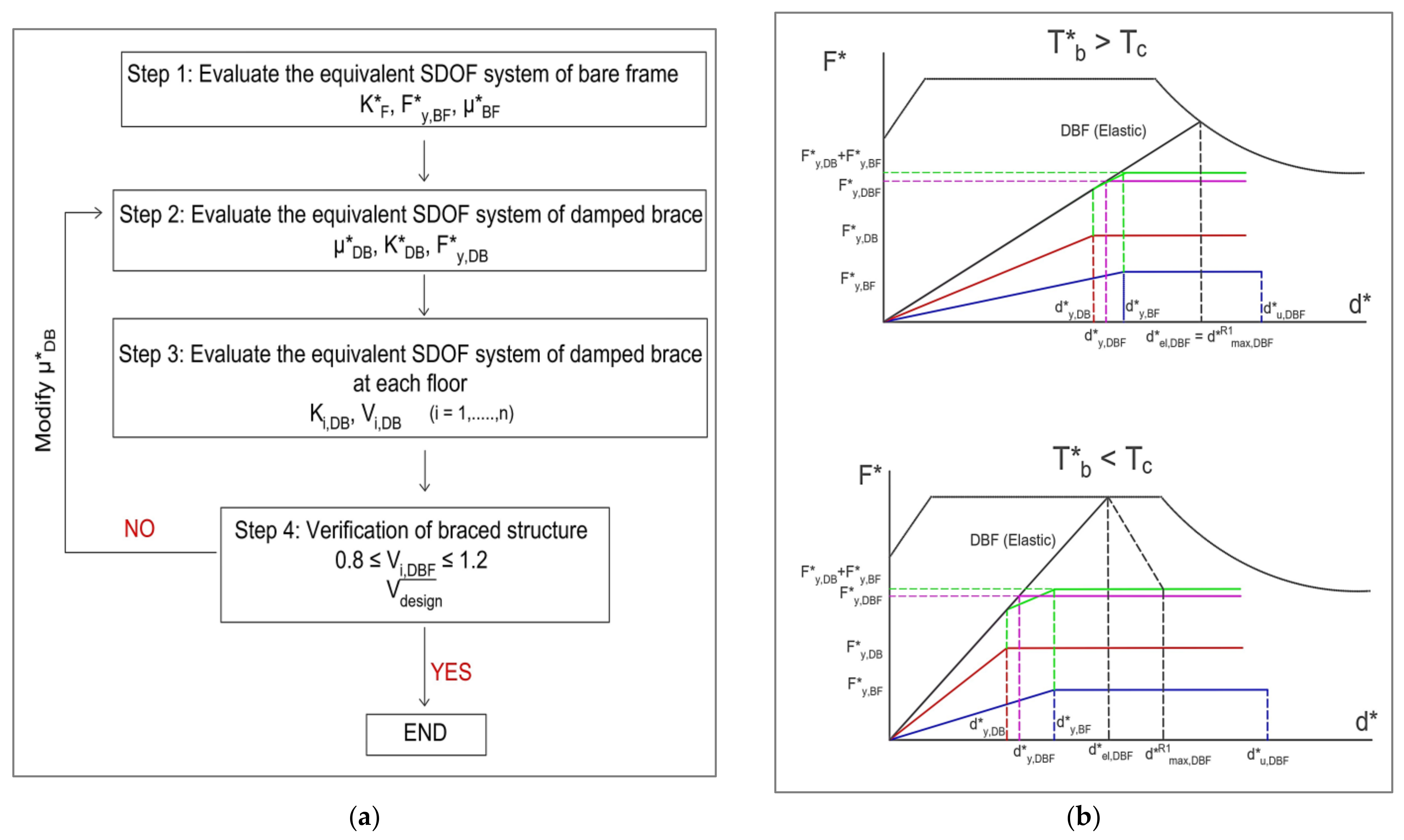
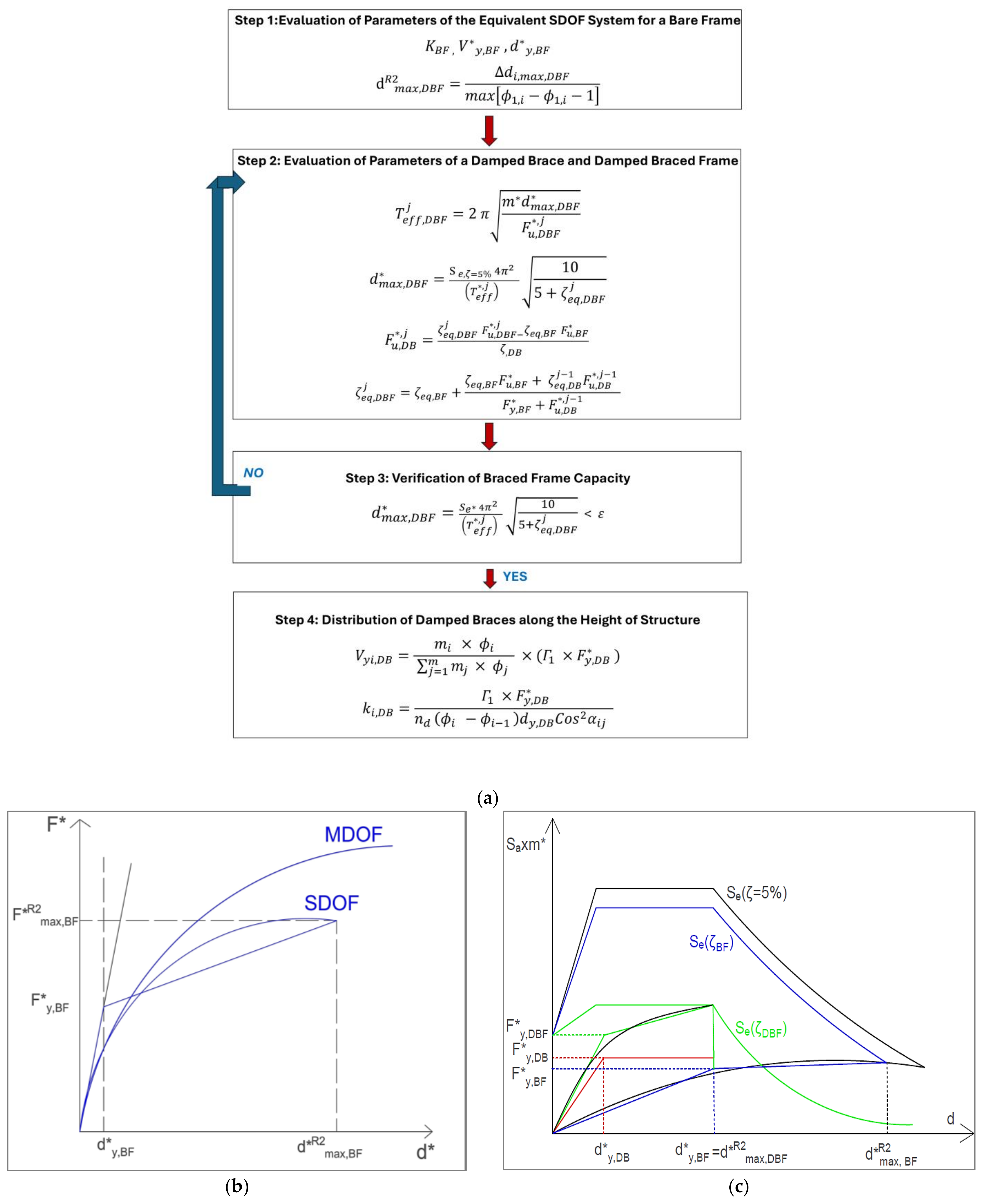
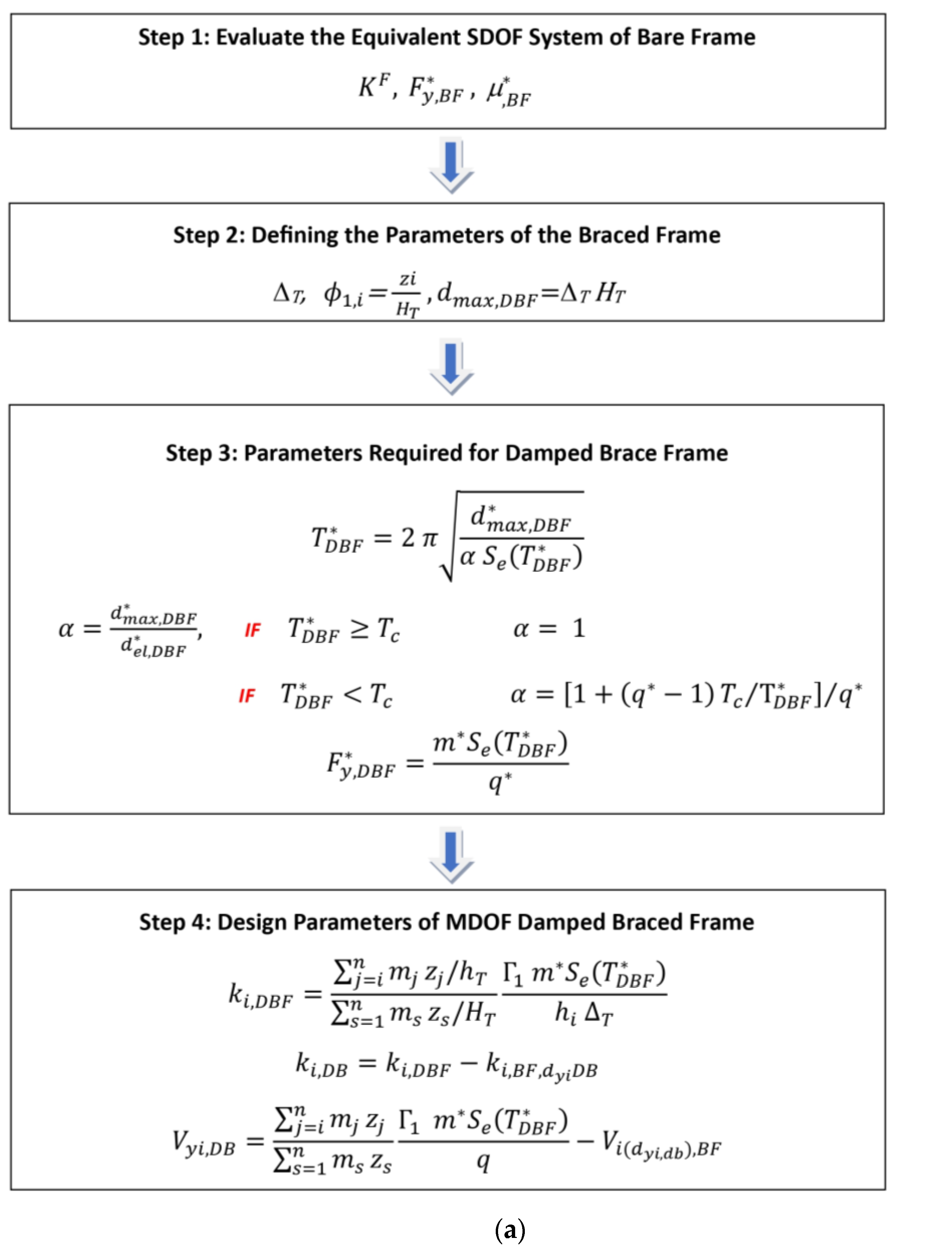
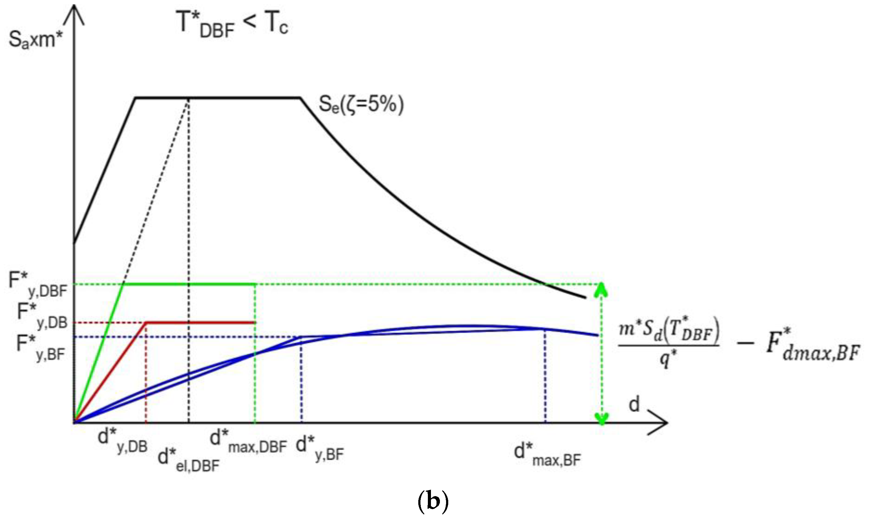
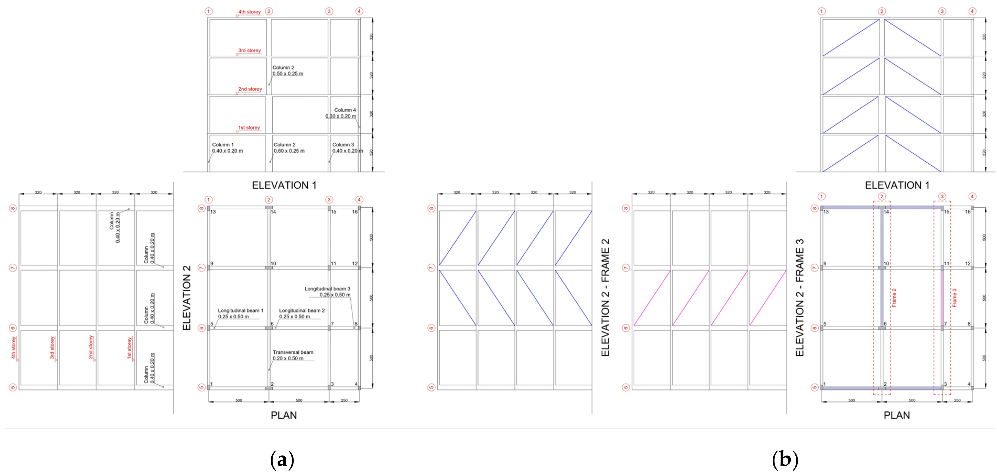
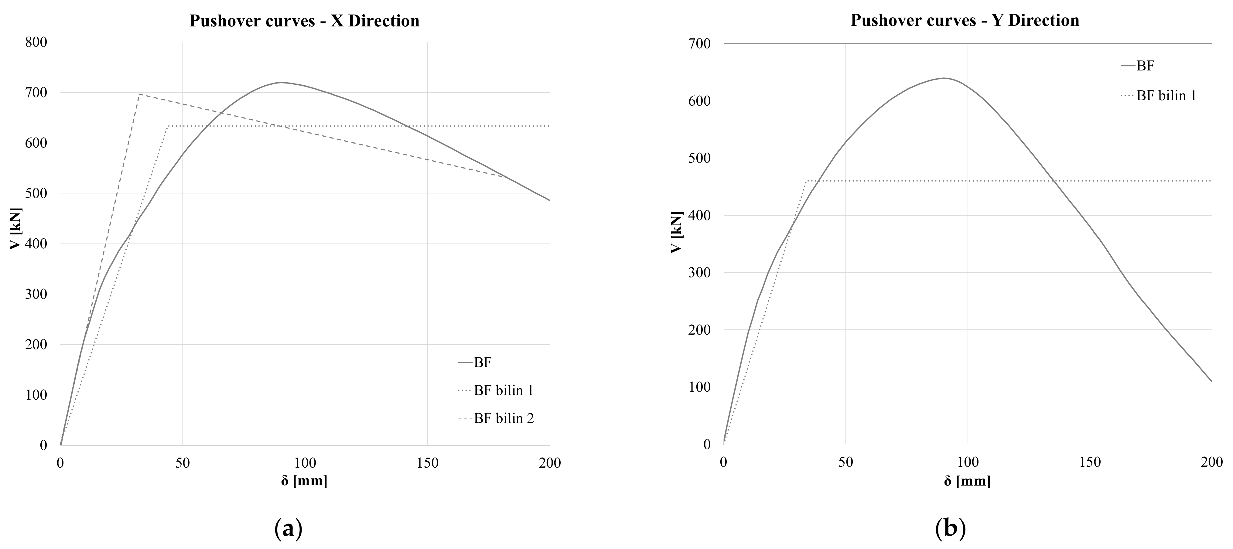
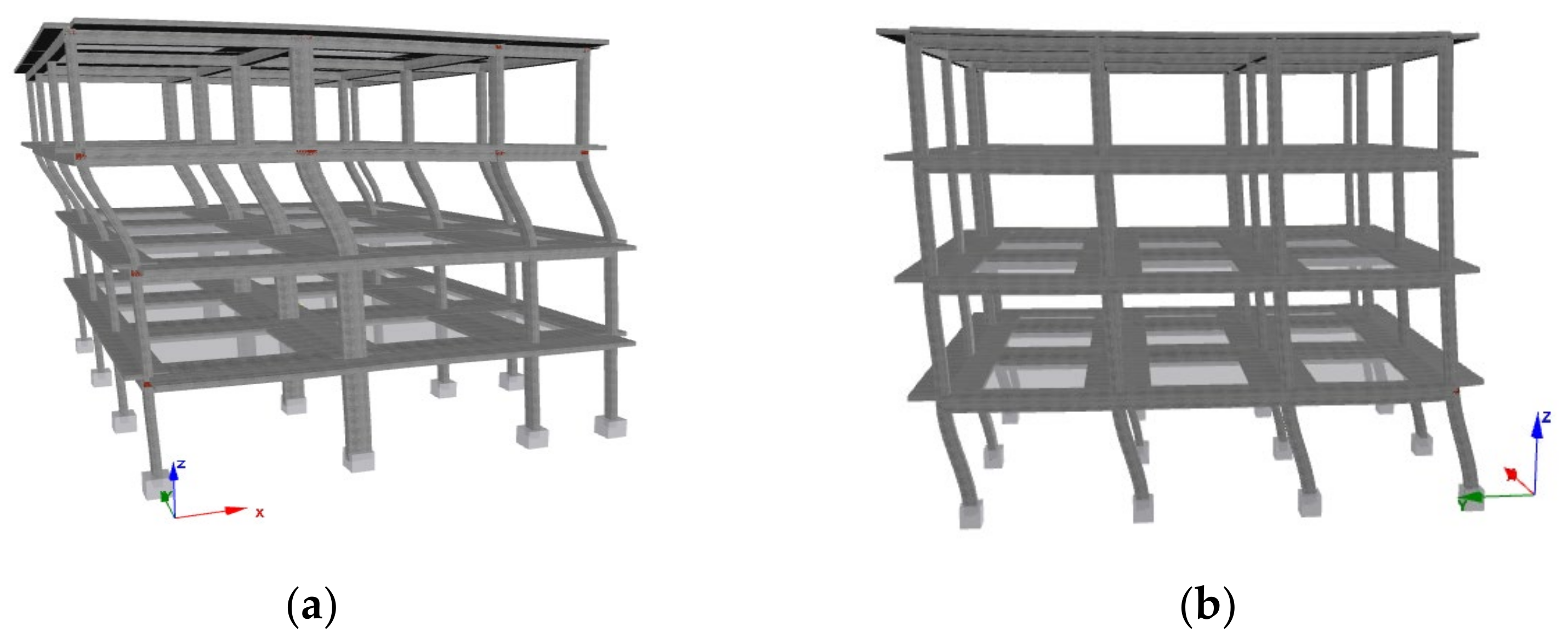
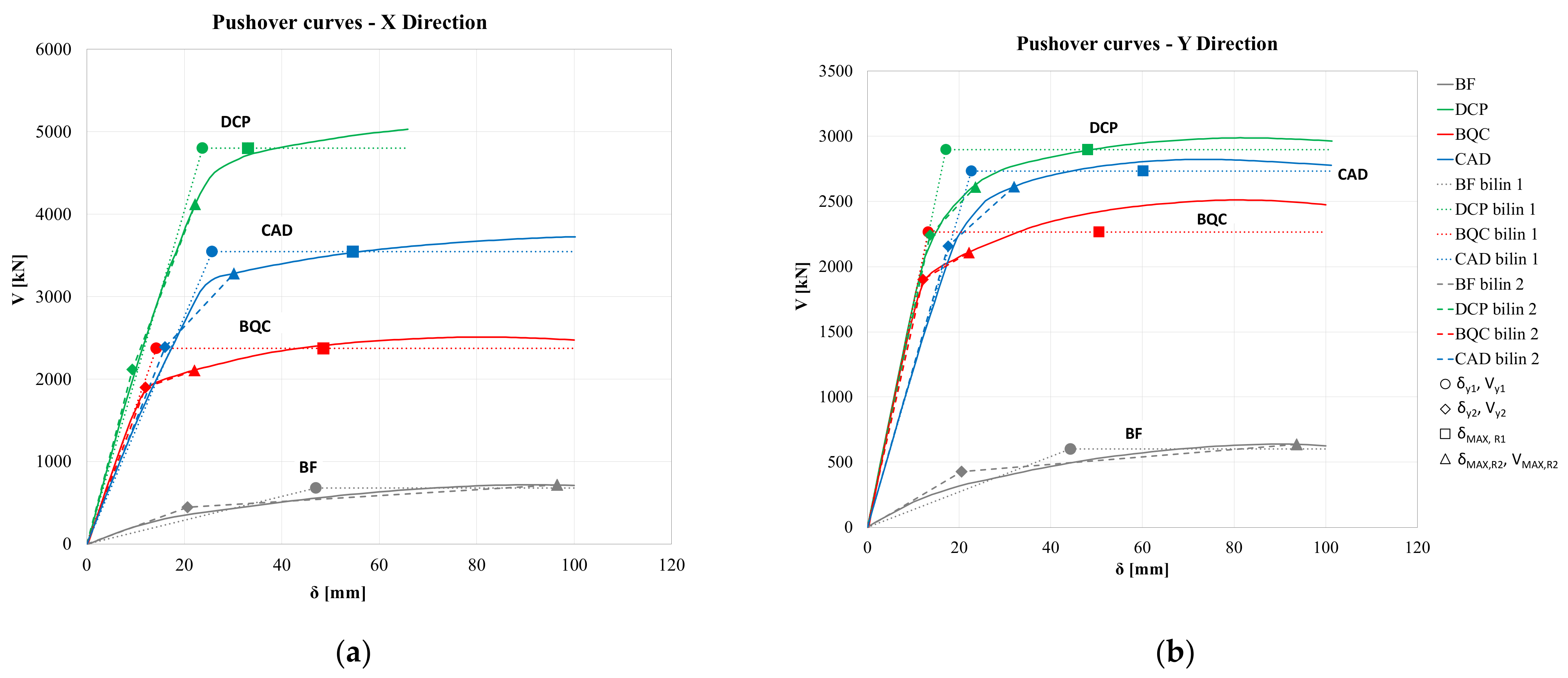

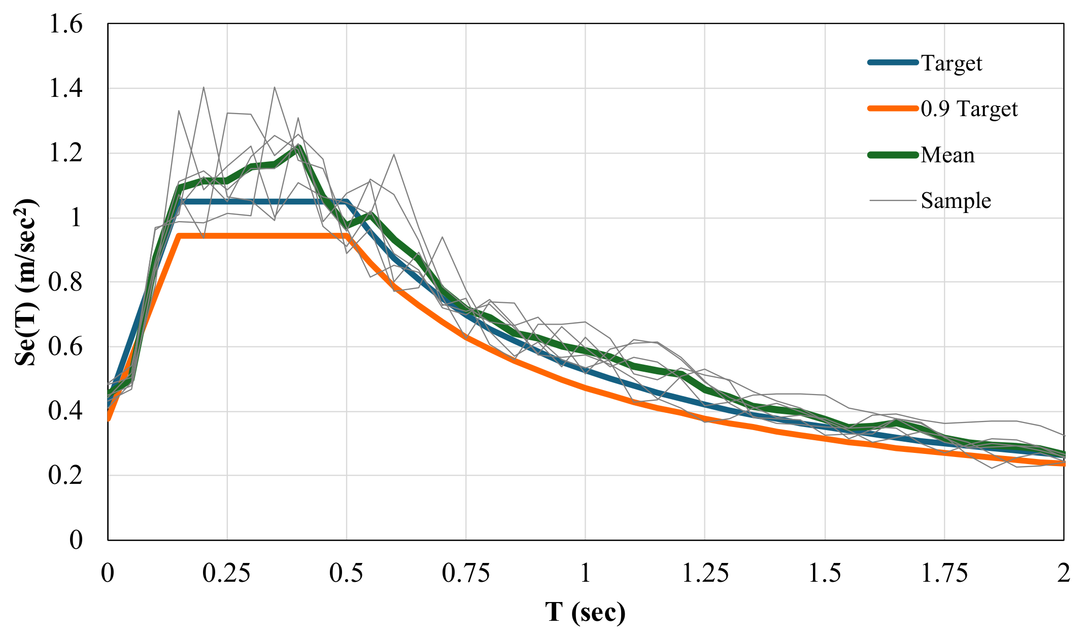
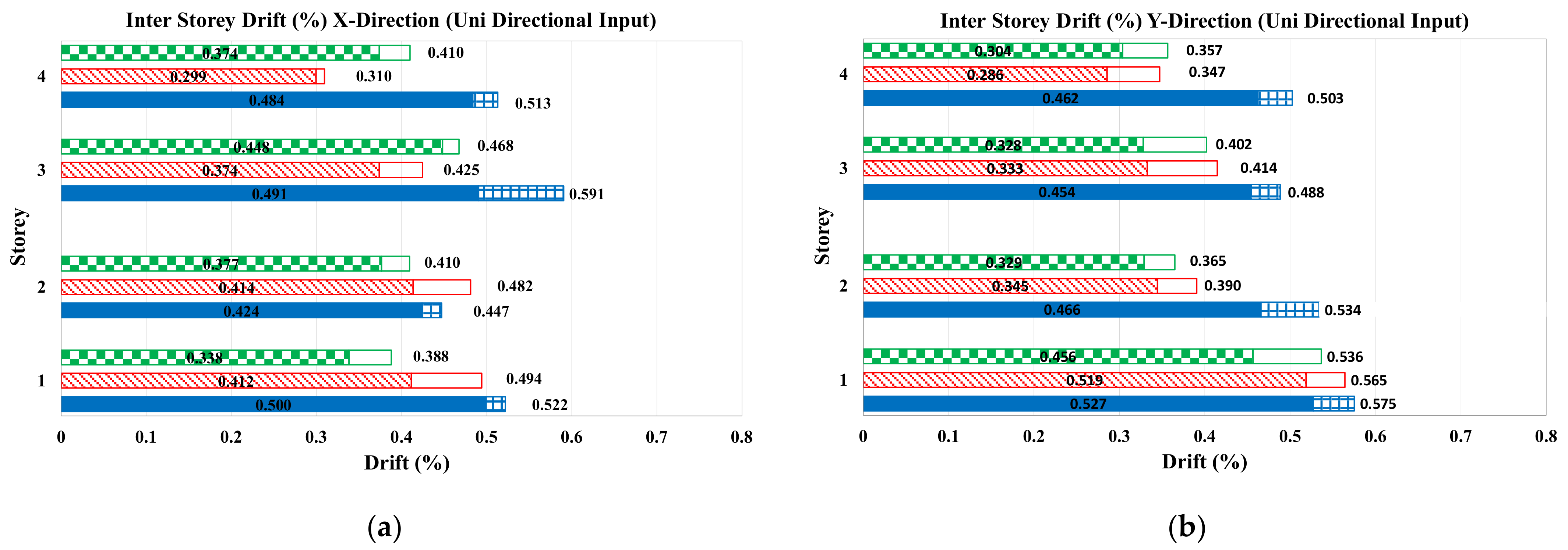

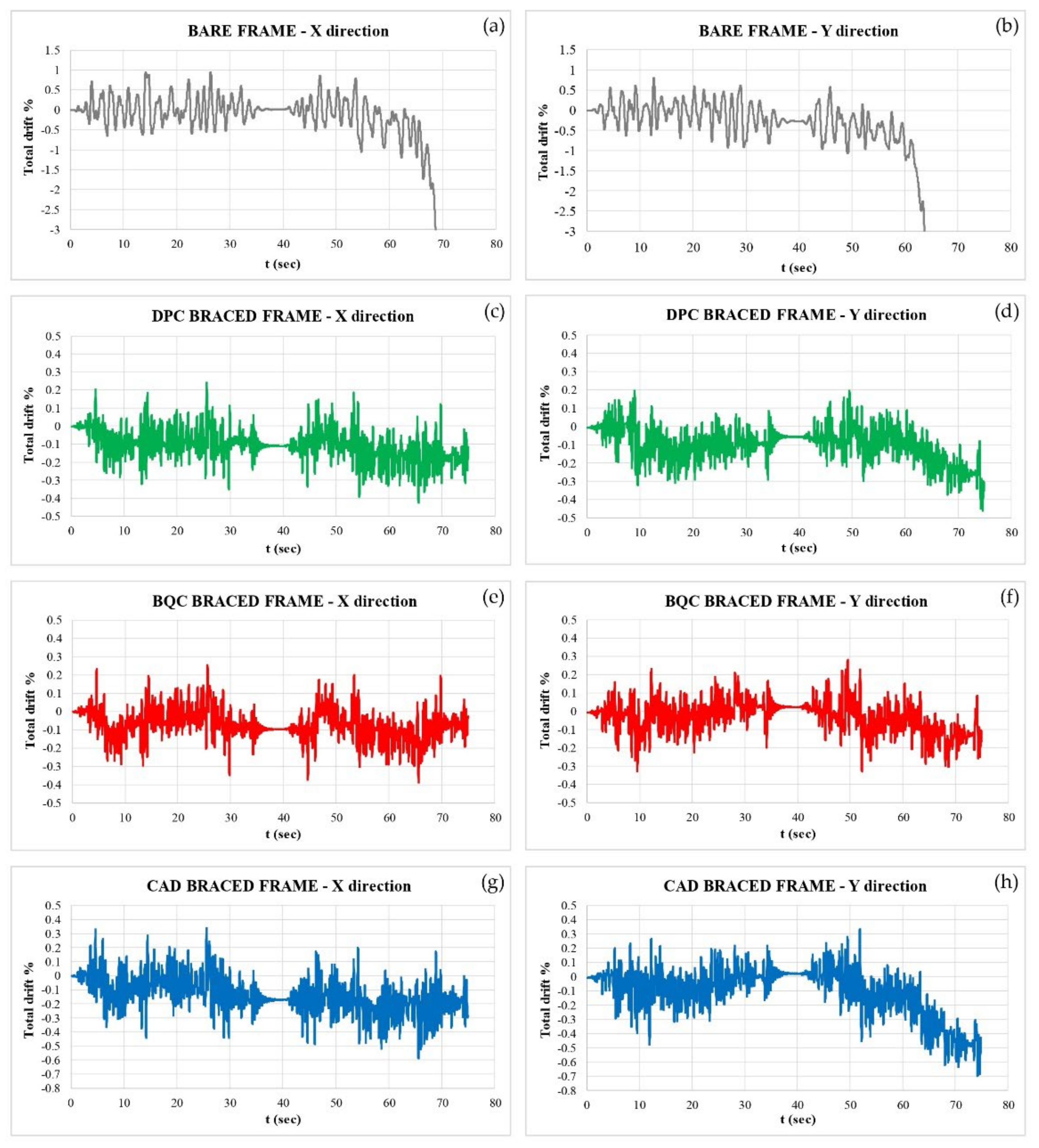
Disclaimer/Publisher’s Note: The statements, opinions and data contained in all publications are solely those of the individual author(s) and contributor(s) and not of MDPI and/or the editor(s). MDPI and/or the editor(s) disclaim responsibility for any injury to people or property resulting from any ideas, methods, instructions or products referred to in the content. |
© 2024 by the authors. Licensee MDPI, Basel, Switzerland. This article is an open access article distributed under the terms and conditions of the Creative Commons Attribution (CC BY) license (https://creativecommons.org/licenses/by/4.0/).