Article

Rib Alignment Control of Long-Span Arch Bridge in Cable-Stayed Buckle by Multi-Objective Optimization

1
Guangxi Beitou Gulf Investment Group Co., Ltd., Nanning 530029, China
2
Guangxi Transportation Science and Technology Group Co., Ltd., Nanning 530007, China
3
Guangxi Beitou Traffic Maintenance Technology Group Co., Ltd., Nanning 530029, China
4
College of Civil Engineering and Architecture, Guangxi University, Nanning 530004, China
*
Author to whom correspondence should be addressed.
Buildings 2024, 14(10), 3281; https://doi.org/10.3390/buildings14103281
Submission received: 20 August 2024 / Revised: 24 September 2024 / Accepted: 14 October 2024 / Published: 17 October 2024

Abstract

:
The construction duration of long-span arch bridges is excessively prolonged due to insufficient closing precision and the non-convergence of traditional cable adjustment calculation methods. This study investigates cable force management in long-span concrete-filled steel tubular (CFST) arch bridges during cable-stayed buckle construction, aiming to improve construction safety and precision in arch rib alignment. Using the Pingnan Third Bridge and Tian’e Longtan Bridge as practical examples, the research develops a multi-objective optimization method for cable forces that integrates influence matrices, constrained minimization, and a forward iterative approach. This method offers a robust strategy for tensioning and cable-stayed buckling, enabling real-time monitoring, calculation, and adjustment during the construction of large-span CFST arch bridges. The results reveal that the iterative approach notably enhances calculation efficiency compared to conventional methods. For instance, field measurements at the Pingnan Third Bridge show a minimal arch closure error of only 3 mm. Additionally, the study addresses concerns about excessive stress in exposed steel tubes during concrete casting. By optimizing the sequence of main arch closure and concrete casting, stress in the exposed steel tube is reduced from 373 MPa to 316 MPa, thus meeting specification requirements. In summary, the multi-objective cable force optimization method demonstrates superior efficiency in determining cable tension and controlling rib alignment during cable-stayed buckle construction of long-span CFST arch bridges.

1. Introduction

The utilization of cable-stayed buckles has demonstrated effectiveness as a widely employed technique for constructing long-span arch bridges. Presently, eight arch bridges with spans exceeding 400 m are operational on a global scale. Notably, the Pingnan Third Bridge and the Tian’e Longtan Bridge feature impressive spans of 560 m (comprising 44 segments) and 600 m (comprising 48 segments), respectively. In CFST arch bridges, the span increases proportionally with the number of arch rib segments, thereby rendering the determination of reasonable cable force and the alignment control of arch rib an intricate process. As such, the construction monitoring of large-span arch bridges poses a significant challenge and calls for precise cable force determination and arch rib alignment control [1,2,3,4,5,6,7].
The present study investigates the optimization and implementation of cable force in the process of cable-stayed buckle construction of a CFST (Concrete Filled Steel Tubular) arch bridge, with primary reference to cable-stayed bridges [8,9]. Various methods have been proposed, including the influence matrix, forward iteration, and backward iteration [10]. However, these methods have limitations such as low computational efficiency, ignoring cable force uniformity, and arch alignment accuracy. To address these limitations, Xu et al. [11] proposed an improved iteration method but did not consider cable force uniformity and arch alignment accuracy. In contrast, Zhang et al. [12] argued that the backward iteration method is incapable of obtaining an accurate solution in complicated constructions due to unknown parameters and nonlinear effects. Therefore, this study proposes an approach to calculate the displacement influence matrix under the arch self-weight and cable forces based on the influence matrix [13,14,15,16,17,18,19]. The objective optimization function is the deviation between the control point and target alignment during construction.
In contrast, the deviation between the arch and its target alignment after arch closure serves as the constrained function. While this method effectively manages the uniformity of cable forces, it does not sufficiently address the accuracy of arch closure or the alignment of upstream and downstream segments. Another approach, known as the influence matrix method, involves adjusting and optimizing cable forces based on the influence degree matrix at each stage. The cable forces for the hoisting segments are calculated according to the construction sequence. However, without appropriate constraints on the influence matrix, the resulting cable forces can be non-uniform, leading to misalignment of the arch and failure to meet the desired objectives.
This study develops a rapid cable regulation method using the influence matrix to achieve high-precision adjustments in the linear shape of cable-structure bridges, such as arch bridges, during construction. This method ensures that the bridge achieves its optimal shape upon completion, aligning with engineering needs while offering notable social and economic benefits. Real-time monitoring throughout construction allows for the identification of deviations from the ideal state, enabling precise regulation and control. This paper presents a study that uses the Pingnan Third Bridge and Tian’e Longtan Bridge as case studies to develop a multi-objective cable force optimization method. The method integrates the influence matrix, constrained minimization, and forward iterative techniques to determine the optimal cable forces during the hoisting of arch rib segments in long-span CFST (Concrete-Filled Steel Tubular) arch bridges. This approach is especially useful for monitoring and optimizing the construction of arch bridges that require one-time tensioning without subsequent cable adjustments. By comparing the in situ measured data, it is found that the measured errors in cable force are within specification limits, and the alignment of the arch rib during installation and after arch closure is satisfactory. Therefore, this multi-objective cable force optimization method provides an effective means of controlling cable forces in long-span CFST arch bridges and offers a valuable reference for similar bridge construction projects.

2. Method and Theory of Cable-Stayed Buckle

2.1. General Solution of Initial Cable Tension and Hoisting Cable Force

The cable-stayed buckle arch bridge’s force calculation is documented in the literature pertaining to cable-stayed bridges [20,21,22,23]. Presently, the optimization and determination of cable force during construction predominantly employ the influence matrix method. The control objective {ΔR} considers the influence of all structural dead load and cable force. The main purpose of the objective function is to reduce the difference between the target value and the model prediction value. An overarching equation to solve for the initial tension of the buckle cable in a CFST arch bridge is established as follows:
A T 0 + Δ S = Δ R
where A represents the unit influence matrix for cable force adjustments relative to control targets; T 0 represents the initial cable tension that needs to be determined; Δ S represents the displacement caused by the dead load during the construction of the arch cable-stayed buckle; Δ R represents the target displacement for the arch bridge design alignment.; m and n are the numbers of elements of Δ R and Δ T , respectively, and m = n.
For the nonlinearity of a long-span arch bridge, the sag effect of the cable is mainly considered at the stage of cable-stayed suspension, and the sag effect is simulated by the equivalent elastic modulus method. In the context of cable-stayed buckle arch bridges, cable tension is determined via iterative forward calculations that utilize the initial tension as a starting point. Notably, the installation of new components occurs tangentially to the previous components. Consequently, the impact of tangential displacement resulting from this installation on the finite element calculation must be accounted for to ensure the calculation results conform to actual engineering requirements. The nonlinearity of the superposition principle is thus introduced, which leads to discrepancies between the calculated cable forces obtained from the influence matrix and the actual tension experienced during installation. Therefore, further optimization and adjustment are required to minimize errors in the tensioning of cables for cable-stayed buckle arch bridge construction that considers the influence of tangential installation displacement.

2.2. Arch Rib Alignment Control Method Based on Multi-Objective Optimization

The innovative multi-objective cable force optimization method proposed herein is based on the iterative analysis of rigid frame structures. This approach simultaneously controls the cable forces in the completed bridge, its geometry, and the displacement of the towers, achieving a one-time tensioning effect without subsequent adjustments to cable forces. It eliminates the need for a sequential adjustment process for orderly tensioning, fundamentally addressing the technical challenges associated with traditional empirical methods that require strict adherence to a predetermined tensioning sequence. If an inappropriate order is chosen for cable tensioning, it necessitates repeated adjustments to achieve design specifications, resulting in complex construction procedures and difficulties in ensuring precision.
When constructing a long-span CFST arch bridge, several factors must be considered to ensure the safety and uniformity of cable forces. These factors include the alignment of the arch rib, the uniformity of cable forces, and safety considerations. The alignment of the arch rib is primarily evaluated based on the cable closure and target alignment, the displacement error of the north and south segments following cable closure, the displacement error of the upstream and downstream sections of the cross brace, and the displacement error of the maximum cantilever end before cable closure. To achieve cable force uniformity and ensure safety during construction, cable forces are optimized by adjusting alignment. The least square method is used to establish the square error function Q, which optimizes cable forces:
Q ( X ) = A s Δ X + d i s 01 d e s t 2 Q = i = 1 m d i s 01 u d e s t j = 1 n Δ α i j Δ X j 2
where Δ α i j represents the change in the jth control target caused by a unit adjustment in the ith cable force.
According to the extreme value theorem, when the objective function Q Δ X takes the minimum value, Δ X k needs to satisfy the following equation,
Q Δ X Δ X k = 0 k = 1,2 , , n
2 i = 1 m d i s 01 u d e s t j = 1 n Δ α i j Δ X j ( α i k ) = 0
Simplified Equation (4) can be obtained:
j = 1 n i = 1 m Δ α i j Δ X j = i = 1 m α i k d i s 01 u d e s t i
Equation (2) can be written in matrix form:
A 1 T A 1 Δ X = A 1 T d i s 01 u d e s t
Equation (4) is a system of linear equations with n unknowns and n equations and the final optimized one-time tension initial cable force T can be obtained by solving the Δ X according to Equation (6):
T = T 0 + Δ X
where T 0 represents the initial cable tension of the control target before adjustment.
The constrained optimization problems are usually transformed into simpler subproblems that can be solved and used as the basis of the iterative process. Based on the solution of the Kuhn–Tucker (K–T) equation, the constrained optimization problem is transformed into an unconstrained optimization problem, and the constraint variables and functions are:
A 0 Δ X + d i s 0 u 0 Δ 0 C 1 Δ X + u 1 Δ 1 C 2 Δ X + u 2 Δ 2 dis 1 Δ x A 0 Δ X Δ s dis 1 k = f i 0 f l i m A 0 = δ 11 0 δ 12 0 δ 1 n 0 δ 21 0 δ 22 0 δ 2 n 0 δ n 1 0 δ n 2 0 δ n n 0 ,   A 1 = δ 11 1 δ 12 1 δ 1 n 1 δ 21 1 δ 22 1 δ 2 n 1 δ n 1 1 δ n 2 1 δ n n 1 ,   A 2 = δ 11 2 δ 12 2 δ 1 n 2 δ 21 2 δ 22 2 δ 2 n 2 δ n 1 2 δ n 2 2 δ n n 2 C 1 = δ 11 1 δ 12 1 δ 1 n 1 δ 21 1 δ 22 1 δ 2 n 1 δ n 1 1 δ n 2 1 δ n n 1 ,   C 2 = δ 11 1 δ 12 1 δ 1 n 1 δ 21 1 δ 22 1 δ 2 n 1 δ n 1 1 δ n 2 1 δ n n 1 ,   C 3 = δ 11 1 δ 12 1 δ 1 n 1 δ 21 1 δ 22 1 δ 2 n 1 δ n 1 1 δ n 2 1 δ n n 1
where d i s 0 represents the actual displacement after cable closure under the initial force t0; d i s 1 represents the actual displacement of the current tension segment under the initial forcee t0; d i s 2 represents the actual displacement of the current transverse brace segment under the initial force; Δ X represents the optimized cable force incremental vector; Δ 0 represents the allowable error in target displacement between the control point after cable closure and the bare arch; Δ 1 represents the upstream and downstream displacement error of the transverse brace segment; Δ 2 represents the displacement error of the largest cantilever before cable closure; C 1 represents the upstream and downstream displacement difference control matrix for the current transverse brace segment; C 2 represents the south and north displacement difference control matrix after cable closure; C 3 represents the displacement difference control matrix of the closure segment; u 0 represents the difference between the total displacement of the initial model and the actual displacement after cable closure under the initial force t0; u 1 represents the displacement difference vector of the south and north arch rib after cable closure under the initial force t0; u 2 represents the displacement difference vector of the upstream and downstream arch rib under the initial force t0; u 3 represents the displacement difference vector of the closure segment; Δ x represents the lower limit of the current constraint tensile segment; Δ s represents the upper limit of the current constraint tensile segment and denotes the cable tension force; f l i m represents the cable-breaking force.
With the aim of achieving alignment, uniformity, and safety in cable tension while maintaining the established status of the bridge, adjustments to the linear configuration of long-span cable-stayed bridges are made by optimizing cable forces during construction. A rapid solution method for determining appropriate installation cable tensions is developed to ensure that the number of tensioning operations is minimized. This approach guarantees that cable forces remain uniform and within permissible safety limits, ultimately leading to an optimal shape for the bridge.

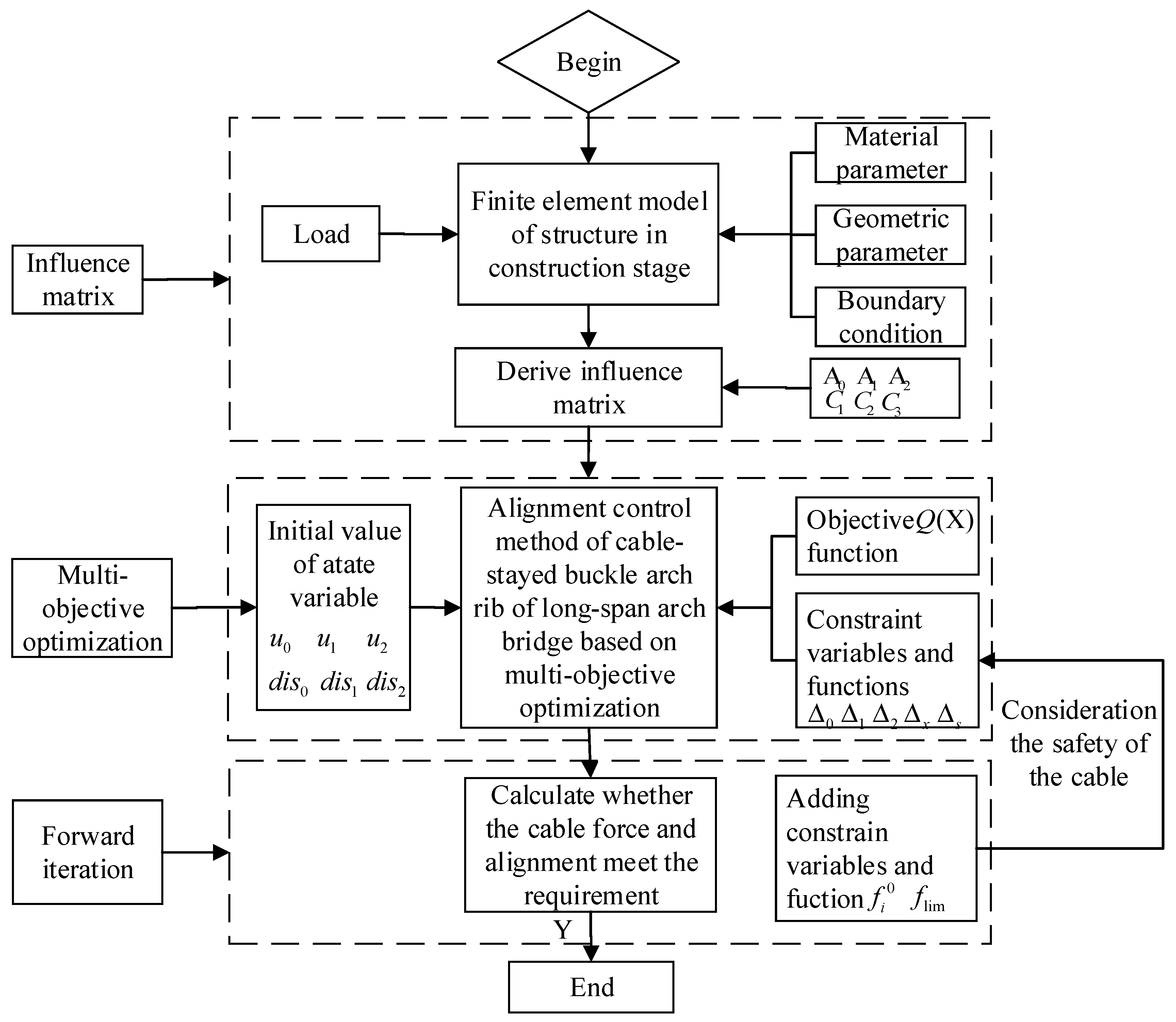
3. Calculation Steps of Arch Rib Alignment Control Based on Multi-Objective Optimization

For long-span CFST arch bridges with numerous segments and intricate construction processes, cable force adjustments must be made repeatedly to satisfy multiple objectives concurrently. This necessitates the involvement of individuals with extensive experience in cable adjustment calculations. However, the tediousness of manual cable adjustment can be eliminated by utilizing MATLAB R2016a. The mathematical formulation implemented in MATLAB utilizes the cyclic loading method to tackle the problem [24,25,26,27]. It is important to ensure that the objective and constraint functions are continuous to prevent the occurrence of a locally optimal solution. In addition, the objective and constraint functions must be real numbers when the fmincon function is used for maximum constraint minimization. The steps involved in solving the alignment control problem of long-span bridge arch ribs using cable-stayed construction and multi-objective optimization are shown in Figure 1.

4. Engineering Applications

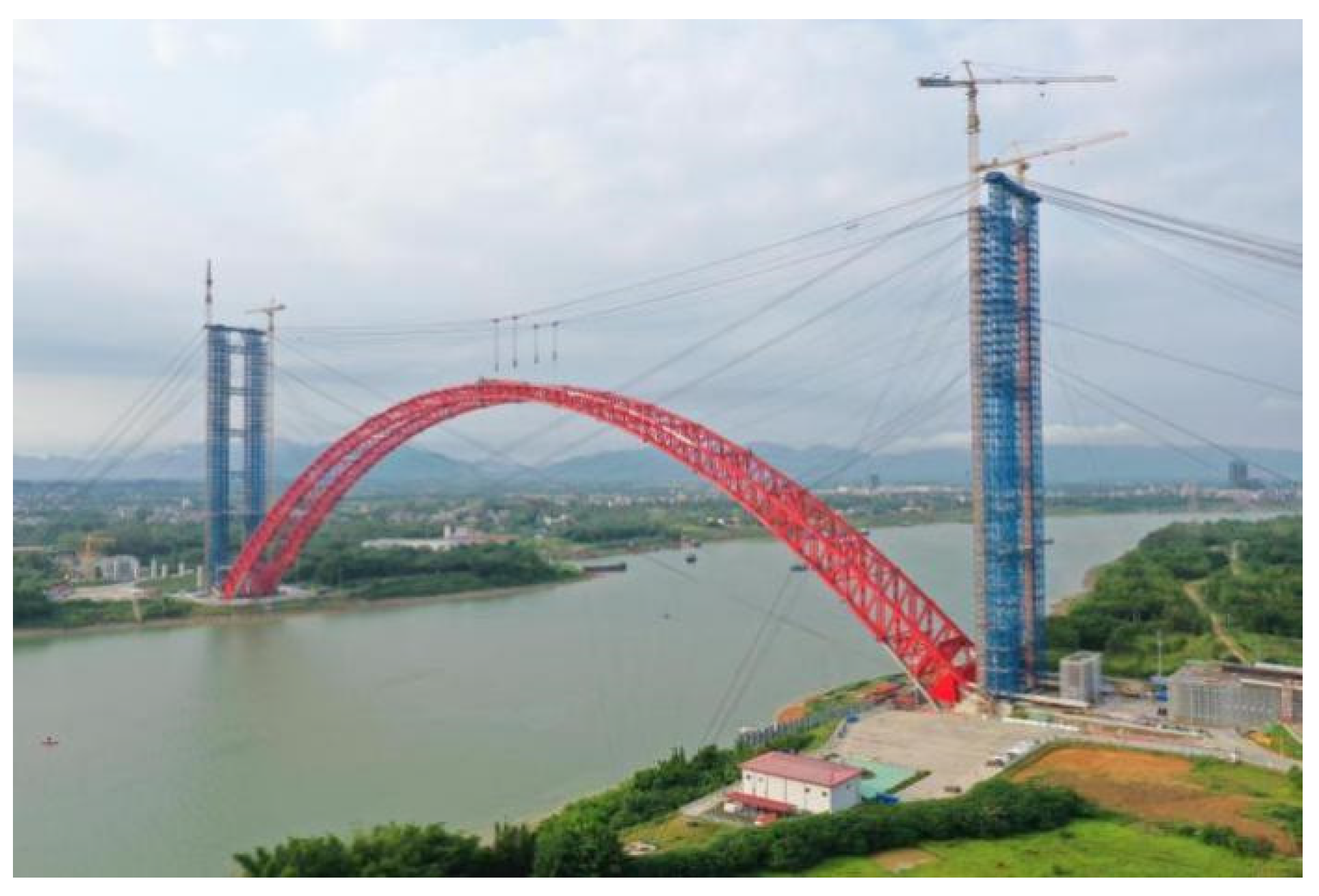
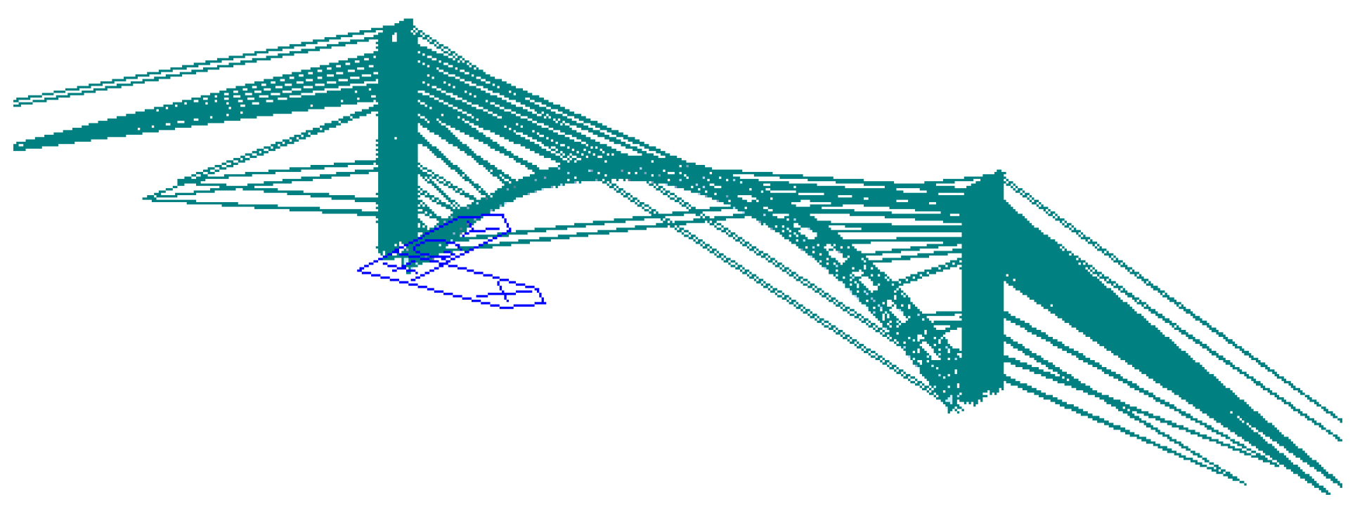
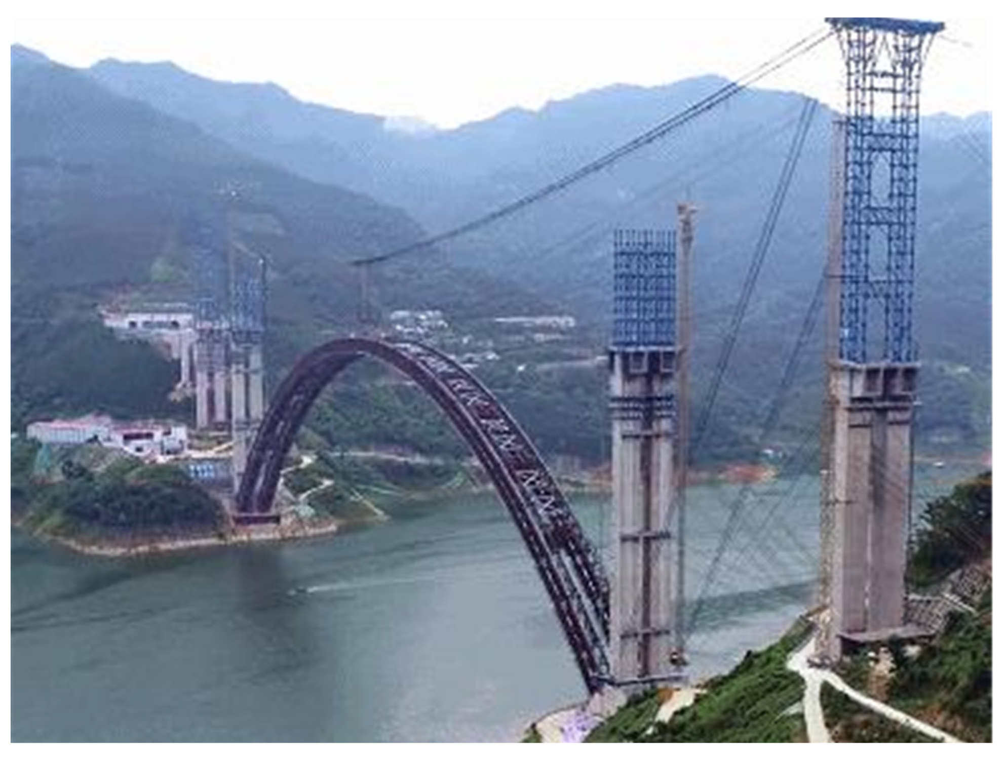
4.1. Engineering Overview and Calculation Model Acquisition

The Pingnan Third Bridge’s cable-stayed buckle system comprises two components: the buckle and the horizontal force adjustment cable. The cable buckle supports the cantilever assembly of the arch rib segment. At the same time, the ground stretching form is incorporated into the design for the safety and convenience of the cable buckle. The horizontal force adjustment cable consists of active and passive adjustment cables. In the event that the buckle tower is affected by unbalanced horizontal forces, the horizontal force adjustment cable regulates the tower’s deviation within a small range, mitigating the influence of the hoisting segment on the buckle segment elevation. The buckle cable was constructed from high-strength, low-relaxation 1860 MPa Φ15.24 mm steel strands, with a single strand’s area and elastic modulus (E) being 140 mm2 and 1.95 × 10⁵ MPa, respectively. The anchor end of the buckle cable is secured with a low retraction anchorage situated close to the hoisting arch rib segment’s end at the buckle point. The overall layout of the cable-stayed buckle method is depicted in Figure 2. The Pingnan Third Bridge’s finite element model comprises 12,321 nodes and 24,251 elements, with material properties, geometric characteristics, boundary conditions, and external load information consistent with the design drawing data. Due to the bridge’s symmetry, the cable buckles are labeled based on the construction stage’s sequence. The modeling assumptions employed include steel’s ideal elastic material property and the plane section assumption for cross-section deformation. The finite element model is presented in Figure 3.
The Tian’e Longtan Bridge, which spans 624 m, is a rib-skeleton concrete arch bridge with a cable buckle design featuring divided cables, whereby the pulling end cable force is equal to the anchoring end. A single-bundle cable force was used during construction, whereas each arch rib segment consisted of two-bundle cables. The buckle cable was constructed of high-strength, low-relaxation steel strands with 1860 MPa Φ15.24 mm. A single steel strand has an area of 140 mm2 and an elastic modulus of 1.95 × 10⁵ MPa. The anchor end comprises a low-retraction anchorage located at the buckle point close to the end of the hoisting arch rib segment. The control point is the intersection point of the arch rib upper axis and the top vertical web axis horizontally translated outward from the main chord during construction. The finite element model of the Tian’e Longtan Bridge has 7614 nodes and 15,545 elements, and its material properties, geometric characteristics, boundary conditions, and external load information are consistent with the design drawing data. The buckles are numbered based on the bridge’s construction stage sequence, owing to its symmetry. The modeling method is similar to that of Pingnan Third Bridge, the solid model is shown in Figure 4 below, and the finite element model is shown in Figure 5.

4.2. Results of Arch Rib Alignment Based on Multi-Objective Optimization

The cable-stayed buckle method finite element model of the Pingnan Third Bridge and Tian’e Longtan Bridge was utilized to extract the displacement change influence matrix of the different construction segment control points, namely, the current tension segment, the current transverse brace segment, and the cable closure segment. This was achieved by considering the cable force of the current arch rib installing segment. In addition, the displacement influence matrix of the bare arch resulting from the weight change of the arch rib and the transverse brace of each segment was also extracted. The alignment operation was employed to solve the influence matrices C 1 ,   C 2 ,   C 3 , which were solved by A 0 ,   A 1 ,   A 2 .
In this study, the arch rib installation stage was simulated based on the final construction sequence, which involved using the tower cable-stayed buckle cantilever assemblage method. The Pingnan Third Bridge and Tian’e Longtan Bridge hoisting stages were divided into 44 and 48 sections, respectively. The cable force was used to balance the arch rib segment self-weight load during the cantilever assemblage. The construction approach involved symmetrical installation on both sides, which started with installing the upstream and downstream arch ribs, followed by transverse connection between the segments, and finally, installing the next segment until cable closure. The objective function aimed to simultaneously satisfy three criteria, including minimizing the sum of squares of the difference between the mean value of the actual displacement of the cantilever end in the arch rib segments installation and the control point displacement of the cantilever end in the arch transverse brace installation caused by the bare arch weight. Furthermore, it sought to minimize the variance between the mean value and target displacement and reduce the influence of the tension buckle cable of the uninstalled segment of the arch rib on the displacement control point of the installed segment. A comparative analysis reveals that for the Pingnan Third Bridge, the inflection point of the optimization function dispersion occurred at delta = 30 mm, with the dispersion increasing exponentially as the delta decreased. When the delta > 30 mm, the dispersion delta tended to smooth; therefore, it is recommended that the difference between the actual and the target displacement of the control point should not be large, and the delta of the Pingnan Third Bridge should be selected between 30 mm to 35 mm. Similarly, the delta of Tian’e Longtan Bridge should be 40 mm~50 mm. This is illustrated in Figure 6 and Figure 7, which show the dispersion and delta variation curves for the Pingnan Third Bridge and Tian’e Longtan Bridge, respectively.

4.3. Solution Results

The analysis results in Section 4.3 demonstrate that the displacement delta between the actual and target values of the cable closure for the Pingnan Third Bridge is 35 mm, while that of the Tian’e Longtan Bridge is 45 mm. The multi-objective arch rib alignment control technique was employed to evaluate the structural construction. The theoretical displacement analysis under the cable tension iteration’s final value is reported in Table 1 and Table 2.
The segmental division of Pingnan Third Bridge is shown in Figure 8 below. The segmental division of Tian’e Longtan Bridge is shown in Figure 9 below.
The multi-objective arch rib alignment control method was analyzed and calculated to investigate the displacement change in different segments’ cantilever end control points, as observed in Figure 10, Figure 11, Figure 12 and Figure 13. The results revealed a more gradual displacement change in comparison to other methods. The control points of the two adjacent sections displayed no significant displacement change, indicating good continuity in construction alignment. After the cable closure of the Pingnan Third Bridge and the Tian’e Longtan Bridge, the error between the control point elevation and the target alignment was 10 mm and 30 mm, respectively. During the hoisting construction of the Tian’e Longtan Bridge, the error between the control point elevation and the target alignment was less than 45 mm. All of the errors observed in the study met the required specifications. These findings demonstrate the effectiveness of the multi-objective arch rib alignment control method in achieving precise alignment during construction.

4.4. In Situ Measurement Comparison

The comparison of in situ and theoretical data is presented using the Pingnan Third Bridge as an example, given that the Tian’e Longtan Bridge is currently under construction. During the in situ monitoring of the Pingnan Third Bridge, a one-time passive adjustment method for cable tension was utilized, and the optimization of cable tension was performed to achieve the convergence goal. Cable closure was carried out at a stable time of elevation and axis change, and the arch rib alignment was continuously monitored in situ. The displacement of the control point is presented in Figure 14 and analyzed using the multi-objective optimization method for arch rib alignment. Results show that the cable closure error of Pingnan Third Bridge is 3 mm. This precision adjustment method for arch rib alignment enabled control of each arch rib’s alignment during the hoisting construction process, while ensuring uniform cable force that met safety requirements. This approach effectively resolved the issue of repeated cable adjustments and offered the advantages of high efficiency and convenience.

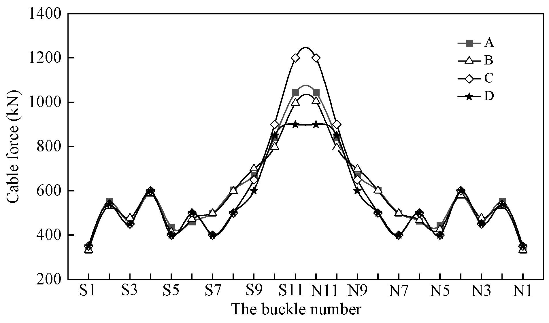
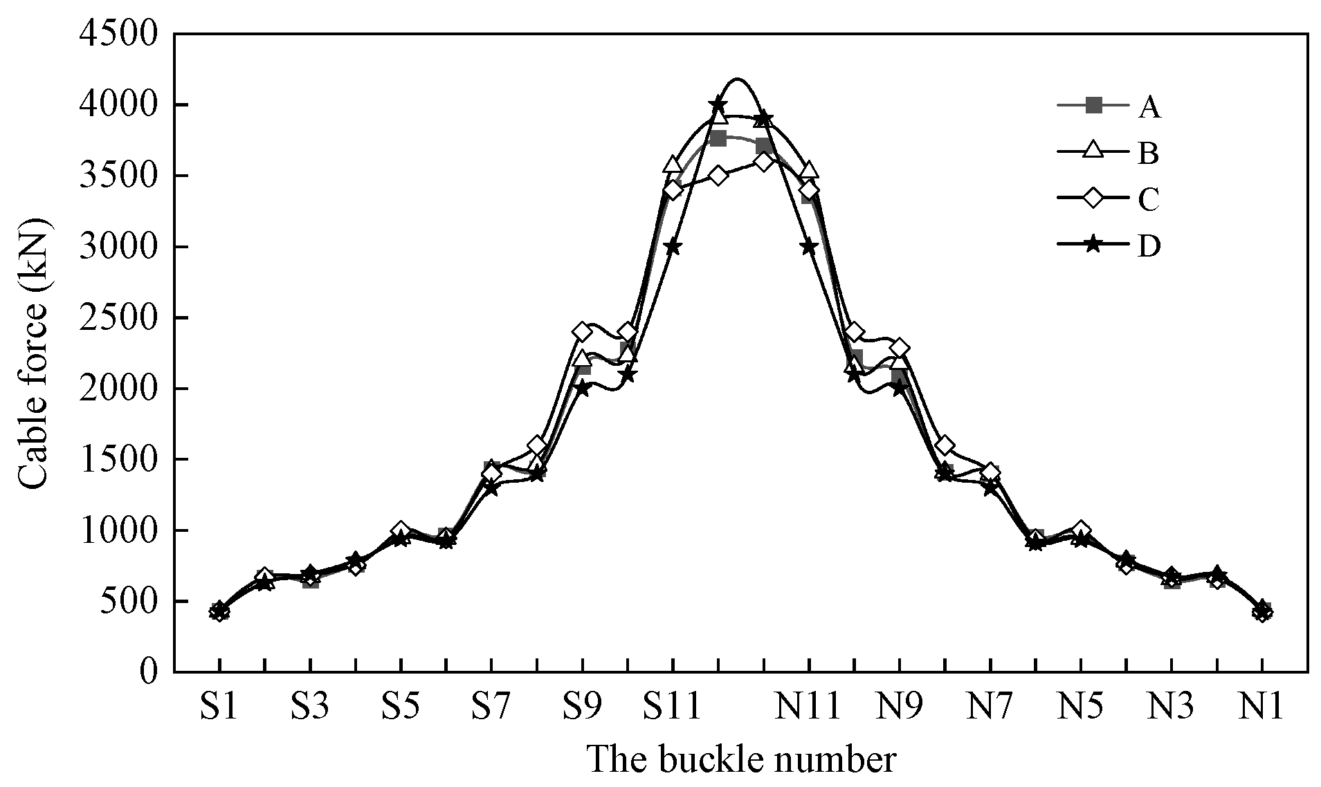
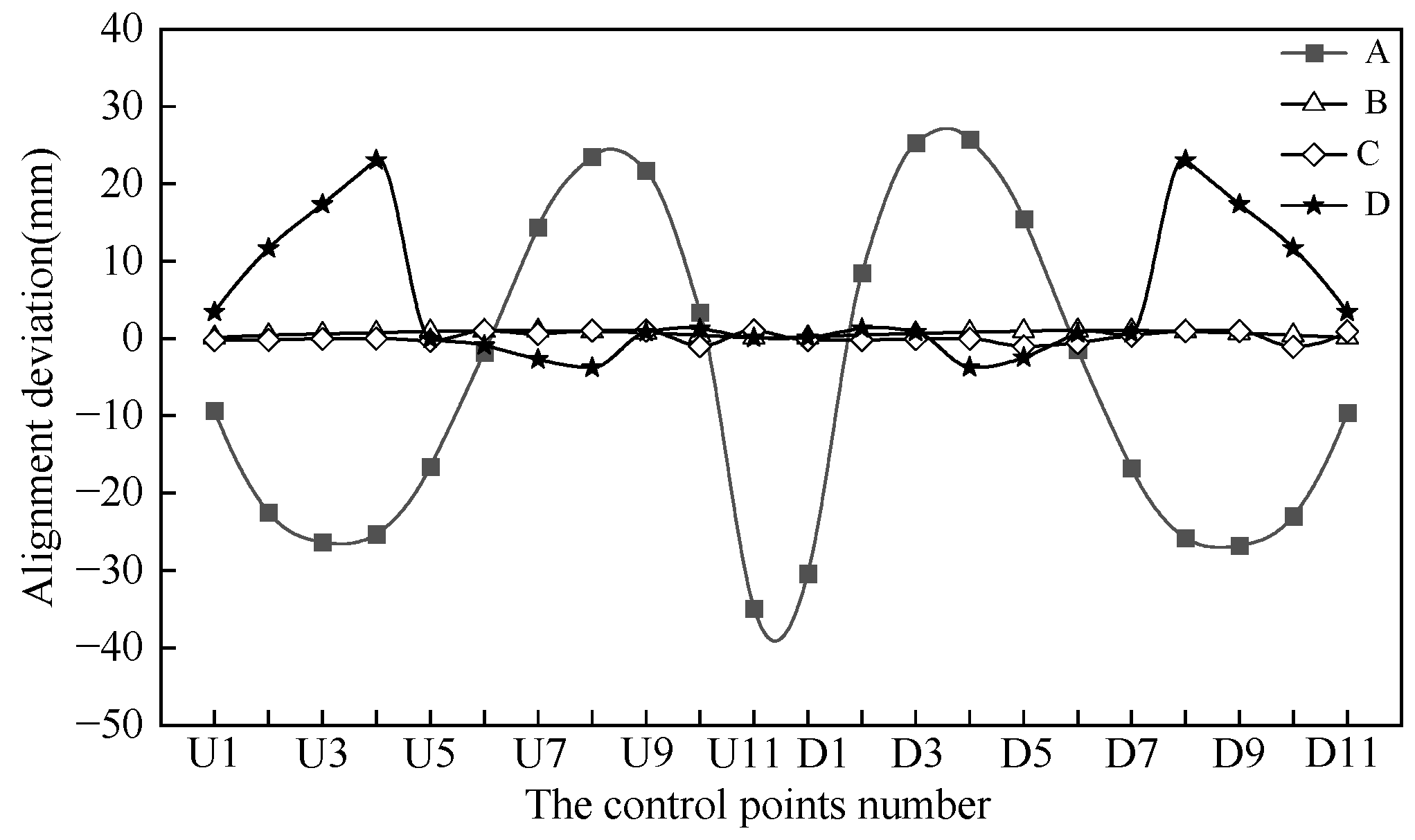
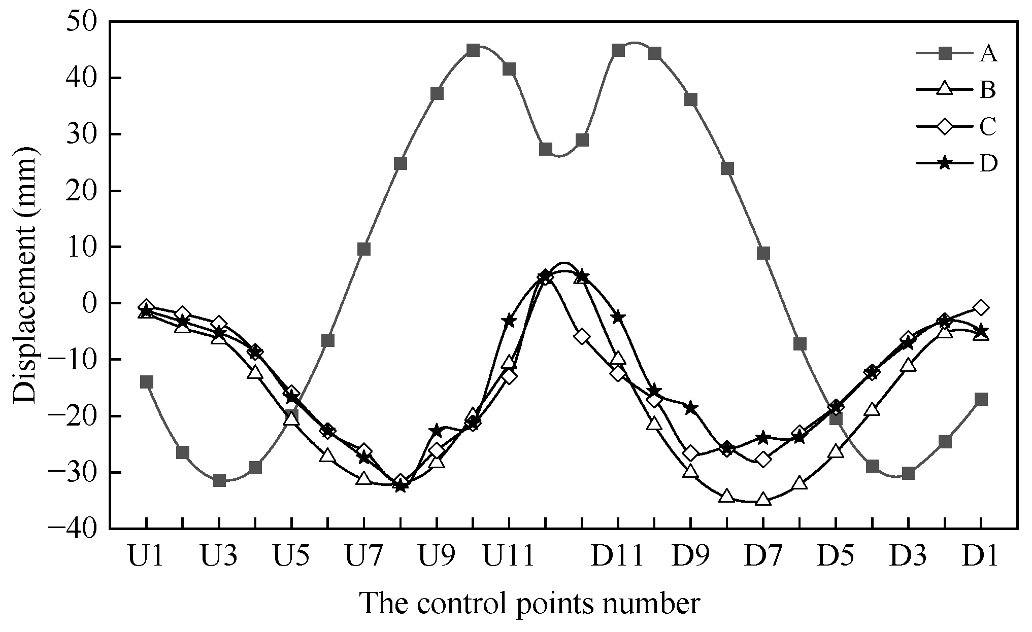
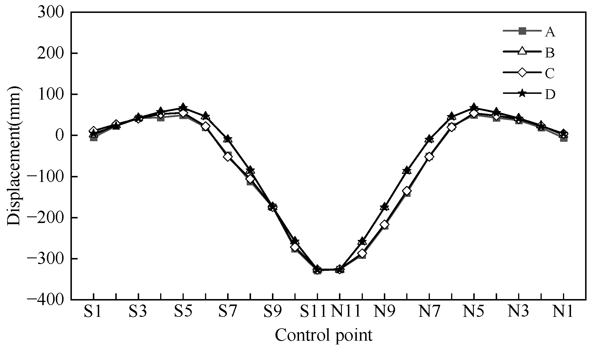
5. Comparative Analysis of Each Optimization Scheme

According to the construction process of the Tian’e Longtan Bridge, the mid-span section of the exposed steel tube stress is the most concerning area. This observation indicates that the cable closure section of the CFST rigid skeleton arch bridge is the most critical and high-risk segment. Consequently, the division of construction stages commenced with the installation of the cable closure. To analyze the stress superposition of the exposed steel tube accurately, the construction stage and sequence were considered and are presented in Table 3.
In the process of constructing a rigid skeleton arch bridge, each stage of construction is characterized by creep, shrinkage, boundary constraints, and changes in structural stiffness due to the application of structural load step by step. The final structure’s mechanical properties and stress state are closely related to the previous stages of construction. Specifically, in the concrete encasement process, the stress state of the exposed steel tube is affected by the previous stress superposition process. Therefore, optimizing the stress of the exposed steel tube requires considering the previous stress process. The construction process can be divided into two main stages: the installation of the rigid skeleton and the concrete encasement. The former is achieved through hoisting and cable-stayed buckle methods. At the same time, the latter is constructed using the multi-point balanced loading method, which ensures the stability of the structure by effectively balancing the stress of each section during construction. Therefore, optimization of the construction process focuses on the design of the rigid skeleton installation and concrete encasement casting schemes, as presented in Table 4.
During the installation phase of the rigid skeleton, the original plan for installing the upstream segments 11 and 12 involved first performing a unilateral cable closure followed by installing the downstream segments 11 and 12. However, an optimized scheme was developed to install the upstream segment 12 only after completing upstream and downstream segments 11 and 12 and to perform the downstream cable closure only after the upstream segment was installed. For the concrete encasement phase, the construction method adopted was the vertical ring and longitudinal section multi-surface casting, resulting in a uniform stress distribution and smooth deformation of the rigid skeleton. The exhaustive method was employed to adjust the sub-ring casting sequence, with the apex of the arch cast first to enhance the strength of the cross-section near the apex and reduce subsequent superimposed stress. Based on the optimized working surface and casting sequence, the stress and deformation process of the structure was calculated, as shown in Figure 15. The optimized cable closure and casting scheme significantly decreased the exposed steel tube’s stress from the original 373 MPa to 316 MPa, meeting the specification requirements.

6. Conclusions

The alignment control problem considered in this study can be summarized as cable force optimization, which is different from the existing cable force optimization, since the arch rib alignment, tower deviation, cable force uniformity, and safety during construction for long-span arch bridges’ cable-stayed buckles are considered. This approach effectively addresses the defects of traditional monitoring and calculation methods. Additionally, this paper proposes a solution to address the impact of temperature by conducting daily measurements at low temperatures. From a construction perspective, it is essential to resolve the issue of arch rib positioning under varying temperature conditions. The following conclusions are drawn:
(1)
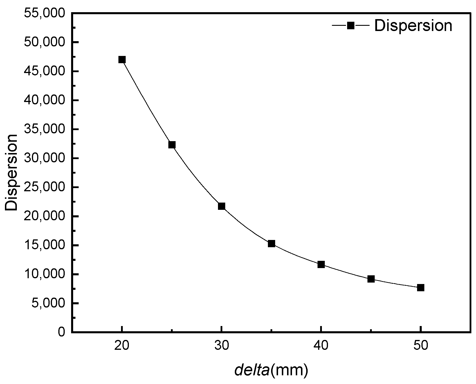
The multi-objective cable force optimization method is an efficient and convenient approach for iterative calculation and engineering applications. It can analyze the relationship between delta and optimization dispersion to determine the difference between actual and target displacement after cable closure under the action of the bare arch.
(2)
In constructing cable-stayed buckle long-span arch bridges, arch rib alignment, cable force uniformity, and safety are considered comprehensively. Optimizing the alignment of cable force during construction ensures that the cable force is uniform and meets specification requirements, effectively overcoming the traditional manual cable adjustment and cable force inhomogeneity issues.
(3)
The alignment deviation in the construction process could affect the cable force. Still, the multi-objective cable force optimization method can ensure precision during arch segment installation, and the arch/bridge completion states meet specification requirements.
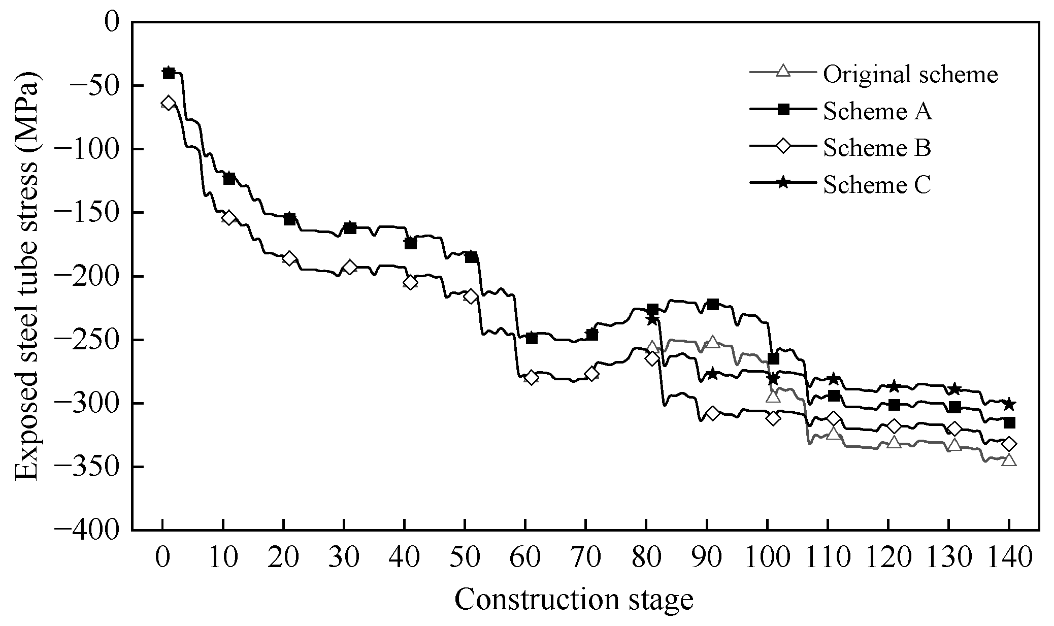
(4)
The control cross-sectional stress of exposed steel tube in rigid skeleton arch bridge is related to the installation method and the concrete casting scheme. To achieve a good stress control effect, selecting the appropriate construction scheme to reduce construction risk is necessary.

Author Contributions

Conceptualization, X.Y. and M.Y.; methodology, L.W.; data curation, X.Y.; writing—original draft preparation, T.H. and N.D.; writing—review and editing, X.Y. All authors have read and agreed to the published version of the manuscript.

Funding

This study was partly sponsored by following funding programs: (1) National Natural Science Foundation of China (Code: 51738004); (2) National Natural Science Foundation of China (Code: 51868006); (3) The Scientific and Technological Project of the Science and Technology Department of Guangxi Province (grant number: 2021AC19125).

Data Availability Statement

The testing and analysis data used to support the findings of this study are included within the article.

Conflicts of Interest

Author Mengsheng Yu was employed by the company Guangxi Beitou Gulf Investment Group Co., Ltd. Author Mengsheng Yu, Xinyu Yao and Longlin Wang were employed by the company Guangxi Transportation Science and Technology Group Co., Ltd. Author Tianzhi Hao was employed by the company Guangxi Beitou Traffic Maintenance Technology Group Co., Ltd. The remaining authors declare that the research was conducted in the absence of any commercial or financial relationships that could be construed as a potential conflict of interest.

References

  1. Zhao, R.; Zhang, Z. A Summary of Development of Concrete-Filled Steel Tube Framed Arch Bridges in China. Bridge Constr. 2016, 46, 45–50. [Google Scholar]
  2. Fan, Y.; Xin, J.; Yang, L. Optimization method for the length of the outsourcing concrete working plane on the main arch rib of a rigid-frame arch bridge based on the NSGA-II algorithm. Structures 2024, 59, 105767. [Google Scholar] [CrossRef]
  3. Tao, T.; Wang, H. Simulation of multivariate ergodic stochastic processes using adaptive spectral sampling and non-uniform fast Fourier transform. Probabilistic Eng. Mech. 2024, 77, 103669. [Google Scholar] [CrossRef]
  4. Tao, T.; Wang, H. Efficient buffeting analysis of long-span bridges under non-stationary winds: A 2D interpolation enhanced approach. J. Sound Vib. 2023, 559, 117754. [Google Scholar] [CrossRef]
  5. Yao, X.; Li, C.; Wang, L.; Yu, M.; Zhuo, X.; Hao, T.; Wang, X. A Practical Approach to Alignment and Error Feedback Control for Long-Span Arch Bridges. Buildings 2024, 14, 1995. [Google Scholar] [CrossRef]
  6. Zhou, Q.; Feng, P.; Zhou, J.; Xin, J.; Wang, J. Analysis of concrete emptying in concrete-filled steel tube arch bridge under uneven temperature field. J. Bridge Constr. 2024, 54, 103–109. [Google Scholar] [CrossRef]
  7. Mou, T.; Fan, B.; Zhao, Y.; Li, S. Application and Development of Steel Pipe Concrete Bridges in China. Highway 2017, 62, 161–165. [Google Scholar]
  8. Zhou, Y.; Wang, Y.; Zhou, J. Arch calculation and control method of 500 m class steel pipe arch bridge. China Highw. 2022, 35, 60–72. [Google Scholar] [CrossRef]
  9. Li, Y.; Li, Y.; Li, J. The calculation method of the whole process cable force optimization of the long-span concrete-filled steel tube arch bridge constructed by cable-stayed suspension method. Prog. Build. Steel Struct. 2019, 21, 33–39. [Google Scholar] [CrossRef]
  10. Xie, K.; Wang, H.; Guo, X.; Zhou, J. Study on the safety of the concrete pouring process for the main truss arch structure in a long-span concrete-filled steel tube arch bridge. Mech. Adv. Mater. Struct. 2021, 28, 731–740. [Google Scholar] [CrossRef]
  11. Xu, Y.; Shen, C.; Zhu, Y.; Wang, C. Improved Iteration Algorithm for Determination of Tension of Fastening Stays for Cantilever Construction of Arch Bridge. Bridge Constr. 2016, 46, 65–69. [Google Scholar]
  12. Zhang, J.; Zheng, J.; Xiao, R. Optimization Calculation and Analysis of Concrete Filled Steel Tube Arch Bridge Hoisting Process. China J. Highw. Transp. 2005, 2, 40–44. [Google Scholar] [CrossRef]
  13. Zhen, J.; Wang, J.; Feng, Z.; Han, Y.; Qin, D. Test on vacuum auxiliary filling technology of concrete-filled steel tube arch section. China Highw. J. 2014, 27, 44–50. [Google Scholar] [CrossRef]
  14. Han, Y. Test and application of vacuum assisted filling of concrete in tubular arch bridge. Bridge Constr. 2015, 45, 19–25. [Google Scholar]
  15. Zhou, D.; Deng, N.; Shi, T. Test and numerical simulation analysis of large scale hydration temperature field of concrete-filled steel tube arch bridge. J. Guangxi Univ. 2021, 46, 51–59. [Google Scholar] [CrossRef]
  16. Sun, J.; Xie, J. Simulation analysis of the hydration heat of large diameter CFST arch and its effects on loading age. Appl. Therm. Eng. 2019, 150, 482–491. [Google Scholar] [CrossRef]
  17. Zhou, Q.; Zhou, J.; Zhang, J.; Zhang, L. Self-regulating loading pouring method of long span CFST arch bridge. J. Harbin Inst. Technol. 2020, 52, 82–89. [Google Scholar] [CrossRef]
  18. Zheng, J.; Wang, J. Chinese steel tube concrete arch bridge. Engineering 2018, 4, 306–331. [Google Scholar] [CrossRef]
  19. Qin, D.; Zheng, J.; Du, H.; Han, Y.; Zheng, J.; Wei, L. Optimization Calculation Method for Stayed-Buckle Cable Force under One-Time Tension by Fastening Stay Method and Its Application. China Railw. Sci. 2020, 41, 52–60. [Google Scholar]
  20. Han, Y.; Qin, D.; Zheng, J. Optimization calculation method for CFST arch bridge cable-stayed suspension construction. Highway 2018, 63, 100–104. [Google Scholar]
  21. Zhou, J.; Liu, J.; Zhou, W.; Yan, R.; Yan, T. Analysis of the influence of temperature changes on the pre lifting value of cable-stayed buckle and the main arch ring shape of steel tube concrete arch bridges. J. China Foreign Highw. 2017, 37, 62–66. [Google Scholar] [CrossRef]
  22. Chen, B.; Wei, J.; Zhou, J.; Liu, J.P. Application of concrete-filled steel tube arch bridges in China: Current status and prospects. China Civ. Eng. J. 2017, 50, 50. [Google Scholar]
  23. Yu, M.; Deng, N.; Wang, L.; Hao, T.; Zhang, Z. Study on Sunshine Temperature Effect in Concrete-filled Steel Tubes Arch Rib of Extra-Large Arch Bridge. Highw. Eng. 2021, 46, 99–104. [Google Scholar] [CrossRef]
  24. Liu, X.; Zhou, G.; Qiu, Y. Optimal Polynomial Time-varying Parameters Discrete Grey Model and Its Applications. Stat. Decis. 2022, 38, 31–36. [Google Scholar]
  25. Li, X.; Wang, C. STI prediction based on metabolic GM (1, 1) Copula BP neural network. Stat. Decis. 2021, 37, 158–161. [Google Scholar] [CrossRef]
  26. Vasques, J.F.; Gonalves, R.G.D.J.; Silva-Junior, A.J.D.; Martins, R.S.; Gubert, F.; Mendez-Otero, R. Gangliosides in nervous system development, regeneration, and pathologies. Neural Regen. Res. 2023, 18, 81–86. [Google Scholar] [CrossRef]
  27. Li, C.; Huang, J.; Li, X. Consider the sunshine temperature field of concrete-filled steel tube arch. Sino-Foreign Highw. 2020, 40, 102–107. [Google Scholar]
Figure 1. Iterative calculation steps of cable force adjustment.
Buildings 14 03281 g001
Figure 2. The elevation view of the Pingnan Third Bridge.
Buildings 14 03281 g002
Figure 3. The schematic diagram of the displacement control point.
Buildings 14 03281 g003
Figure 4. Elevation of Tian’e Longtan Grand Bridge.
Buildings 14 03281 g004
Figure 5. The schematic diagram of the cable-stayed buckle construction.
Buildings 14 03281 g005
Figure 6. Relationship curve between dispersion and delta of the Pingnan Third Bridge.
Buildings 14 03281 g006
Figure 7. Relationship curve between dispersion and delta of the Tian’e Longtan Bridge.
Buildings 14 03281 g007
Figure 8. Arch rib segment division (Pingnan Third Bridge) (the number indicates the arch rib segment number).
Buildings 14 03281 g008
Figure 9. Arch rib segment division (Tian’e Longtan Bridge) (the number indicates the arch rib segment number).
Buildings 14 03281 g009
Figure 10. The comparison diagram of the initial iteration cable tension and optimized cable force of Pingnan Third Bridge (unit: kN). Note: S = South, N = North, A = Cable force after upstream optimization, B = Cable force after downstream optimization, C = Cable force before upstream optimization, D = Cable force before downstream optimization.
Buildings 14 03281 g010
Figure 11. The comparison diagram of the initial iteration cable tension and optimized cable force of the Tian’e Longtan Bridge (unit: kN). Note: S = South, N = North, A = Cable force after upstream optimization, B = Cable force after downstream optimization, C = Cable force before upstream optimization, D = Cable force before downstream optimization.
Buildings 14 03281 g011
Figure 12. The displacement result diagram of the Pingnan Third Bridge. Note: U = Up, D = Down, A = The difference between the alignment of the after cable closure and the target displacement, B = The displacement difference between south and north after cable closure, C = The displacement difference between the upstream and downstream of the installed horizontal brace segment, D = The displacement difference between south and north in the current tension stage.
Buildings 14 03281 g012
Figure 13. The displacement result diagram of the Tian’e Longtan Bridge. Note: U = Up, D = Down, A = The difference between the alignment of the after cable closure and the target displacement, B = The displacement difference between south and north after cable closure, C = The displacement difference between south and north in the current tension stage, D = The displacement difference between the upstream and downstream of the installed horizontal transverse brace segment.
Buildings 14 03281 g013
Figure 14. The displacement of in situ measured and theoretical of the Pingnan Third Bridge. Note: S = South, N = North, A = The upstream in situ measured displacement, B = The upstream theoretical displacement, C = The downstream in situ measured displacement, D = The downstream theoretical displacement.
Buildings 14 03281 g014
Figure 15. The comparison diagram of stress optimization schemes for the Tian’e Longtan Bridge.
Buildings 14 03281 g015
Table 1. The theoretical displacement calculation results of Pingnan Third Bridge (mm).
SegmentThe Target Displacement After Cable ClosureThe Actual Displacement After Cable ClosureThe Actual Displacement of the Current Tension SegmentThe Actual Displacement of the Current Transverse Brace SegmentRelative Error of Actual Displacement to Target
1−5−140−11−9
2−15−388−32−23
3−23−499−44−26
4−33−58106−54−25
5−54−71−11−80−17
6−77−7925−87−2
7−100−86−97−18014
8−119−95−51−20724
9−137−115−191−29222
10−152−149−84−3533
11−162−197−322−329−35
Table 2. The theoretical displacement calculation results of Tian’e Longtan Bridge (mm).
SegmentThe Target Displacement After Cable ClosureThe Actual Displacement After Cable ClosureThe Actual Displacement of the Current Tension SegmentThe Actual Displacement of the Current Transverse Brace SegmentPercentage of Error Between Actual Displacement and Target Displacement
1−6−20−5−15−14
2−14−41−14−35−27
3−28−59−31−53−31
4−56−85−59−69−29
5−98−118−105−152−20
6−150−156−156−180−6
7−208−199−216−3029
8−270−245−277−34725
9−333−295−339−43438
10−384−339−388−49045
11−415−374−417−46441
12−423−395−420−50628
Table 3. The construction stage division of the Tian’e Longtan Bridge.
StageConstruction Stage Content
CS1Install 12 segment rigid skeleton
CS2-CS6Install cable closure segment and transverse braces
CS7Dismantle cable
CS8Dismantle interim transverse brace
CS9-CS24Casting and activating concrete in the tube
CS25-CS26Casting and activating permanent transverse braces
CS27-CS62Bottom concrete encasement stage
CS63-CS68Activate bottom stiffness
CS69-CS110Web concrete encasement stage
CS111-CS115Activate web stiffness
CS115-CS144Top plate concrete encasement stage
Table 4. The optimization scheme of the Tian’e Longtan Bridge.
The Optimization SchemeOptimization StageOptimization Content
ARigid skeleton installation stageOptimize the cable closure scheme
BConcrete encasement casting stageOptimize the web casting sequence
CRigid skeleton installation stage Concrete encasement casting stageOptimize the sequence of cable closure and web casting at the same time
Disclaimer/Publisher’s Note: The statements, opinions and data contained in all publications are solely those of the individual author(s) and contributor(s) and not of MDPI and/or the editor(s). MDPI and/or the editor(s) disclaim responsibility for any injury to people or property resulting from any ideas, methods, instructions or products referred to in the content.

