Abstract
Given the functional and aesthetic quality expected from concrete surfaces, this study investigated the influence of different formwork materials on their surface density, porosity, voids, and elementary chemical composition by relying on X-ray Microtomography (μCT), Scanning Electronic Microscopy (SEM), and Energy Dispersive X-ray Spectroscopy (EDS). The formwork materials assessed were galvanized steel, regular plywood (pink), marine plywood, polyvinyl chloride (PVC), and silicone. μCT showed that distinct formwork affected the surface density of the concrete. In this case, specimens cast within silicone and marine plywood had similar pore volumes although different pore sizes, whereas PVC led to the highest pore volume with small pore sizes. Galvanized steel and regular plywood resulted in similar porosity. SEM showed that the concrete surfaces produced with marine plywood formwork had the highest void content. EDS identified surface products resulting from the contact of concrete with the different formwork materials, suggesting the potential migration of chemical elements. This research significantly contributes to optimizing formwork material selection and enhancing concrete quality and durability. Moreover, it establishes a foundation for further investigations into how formwork materials affect concrete surfaces and the pathological manifestations potentially arising from the molding process.
1. Introduction
There is considerable interest in the functional and visible aspects of concrete surfaces [1], given their relevance to the durability of structures, their role in limiting the entrance of aggressive agents [2], and the ongoing exploration of concrete for aesthetic purposes [3]. Since additional coating systems are often reported to prevent the penetration of external aggressive agents into the concrete and, thus, to improve the durability of the structures [4,5], the importance of concrete surfaces with durable characteristics is clear.
Nevertheless, studies have yet to address the influence of formwork materials on concrete surfaces. Indeed, several studies focus on casting materials as containers for fresh concrete until the hardened state, the demolding procedure, and the permeability of the mold and its impact on concrete strength [6,7,8,9]. However, investigating whether varied formwork materials influence the concrete surface is fundamental to understanding pathologies that may impair the durability of buildings. For example, the surface microstructure is essential in the concrete interface with potential additional coatings [10]. Additionally, formwork parameters are listed along with the raw materials selection and construction processes as significant in obtaining apparent fair-faced concrete of good quality [11].
Through computed tomography, Sadowski and Stefaniuk [12] evaluated the heterogeneity and microstructural properties of the raw concrete surface produced directly after contact with the formwork, mechanically grounded, or shotblasted, verifying that the thickness and concrete surface characteristics varied with the different treatments. A study by Liu et al. [10] sought low concrete surface porosity by comparing conventional molding methods (steel molds) and molds with a controlled permeable formwork (CPF) liner. In a study by He et al. [13] analyzing 3D-printed concrete, the quasi-exponential distribution of interfacial void lengths, with an exponential decrease in the probability of void occurrence beyond twice the surface node interval, significantly affects interlayer strength. This strength decreases non-linearly with increasing void ratio, following a function that can be well-approximated by a combination of exponential and linear functions.
Lim et al. [14] investigated concrete micropore and microstructure characteristics when molded within insulated gang forms, observing improved workability, safety, and initial quality. Pan et al. [3] studied the aesthetical surface quality of concretes molded with plywood formwork with epoxy resin and other polymeric molds, concluding that, generally, smoother casting led to smoother specimens irrespective of their polarity, wettability, and thickness; low friction molds and formwork composed of mixed polymers resulted in higher surface porosity, damaging reflection [3]. Jiang et al. [15] concluded that formworks determine the surface area roughness of concretes, indicating that plywood is more favorable for surface quality than steel; furthermore, mineral oil led to higher surface voids [15]. Mohseni et al. [16] also obtained lower surface roughness for concretes produced with polymeric-coated formwork rather than mineral and vegetable oils.
X-ray computed tomography is a usual approach to investigate cementitious systems in a non-destructive way [17], revealing the pore structure of the specimens [18]. Xu et al. [19] used synchrotron X-ray Microtomography (μCT) to study water distribution, absorption, and the microstructure of ancient Roman concrete samples extracted from Pompeii. X-ray μCT can even be combined with machine learning techniques [20,21], and its association with Scanning Electronic Microscopy (SEM) and Energy-Dispersive X-ray Spectroscopy (EDS) allows the further investigation of morphology, microstructure, and elemental compositions of materials [22].
So, this research discusses the influence of formwork materials used to contain the concrete from its fresh state up to the hardened state regarding microstructure, porosity, surface density, and the presence of chemical elements deriving from the molding materials. The topic’s significance relies on seeking better adhesion and adherence to external coatings applied to concrete substrates. Moreover, the study intends to contribute to the investigation of whether concrete deterioration may begin at the time of molding, regarding, for instance, the emergence of chloride ions and carbonation processes. By critically examining these aspects, this research offers significant contributions to optimizing formwork material selection, ultimately enhancing the quality and durability of concrete. Furthermore, this study paves the way for further investigations into the influence of formwork materials on concrete surfaces and the potential pathological manifestations that may arise from the molding process.
2. Materials and Methods
2.1. Materials
Regarding concrete production, the cement type used was Brazilian Portland Cement CP V-ARI (similar to the American Portland cement with High Early Strength (III and HE) [23]). Table 1 presents the cement’s physical characterization, with data provided by the manufacturer.

Table 1.
Characterization of the cement used in concrete production.
The concrete was produced with a basaltic coarse aggregate with a 7.11 fineness modulus, dimensions ranging from 9.5 to 25 mm, a specific density of 2.98 g/cm3, and a 1.38 g/cm3 unit weight. The fine aggregate was quartz sand from the Jacuí River, with a 2.22 fineness module and a maximum dimension of 2.24 mm. Tap water was used for the concrete production.
2.2. Concrete Production
Five different formwork materials were used for casting the concrete, aiming to evaluate the impacts on its surface. The selected materials were galvanized steel, regular plywood (pink), marine plywood, polyvinyl chloride (PVC), and silicone. Although both the regular and the marine plywood are composites produced by gluing together sheets of wood, solely the marine plywood is externally coated with a phenolic resin, which enhances its resistance to water and facilitates the removal of the casting. One of the advantages of using plywood is its availability in several thicknesses and lengths, with it being extensively used in construction [28]. Table 2 shows the elementary chemical composition of the casting materials and extra additives or finishing, following the existing literature.
Table 2.
Chemical composition and extra additives or finishing for the formwork materials used on the concrete casting. Caption: n = polymer chain length.
The concrete was produced with a mass proportion of 1:3.0 (cement:aggregates). The mortar content was 53%, as determined by the EPUSP/IPT dosage method [32], and the water-to-cement ratio was 0.38. The slump test resulted in 110 mm ± 2 mm, following NBR 16889 [33].
For the primary tests of this research, cylindrical concrete specimens with 10 cm × 2 cm were produced within the different formwork materials. Curing was performed in a climate-controlled chamber with a relative humidity of 96% ± 2% for 28 days. After curing, the 10 cm × 2 cm specimens were split into volumes lower than 1 cm3, one for each type of formwork, prioritizing the obtention of areas in contact with the molds to investigate their impact on the surface quality; the size of the specimens was defined due to the capacity of the experimental tests. Furthermore, three specimens cast in 10 cm × 20 cm cylindrical metallic molds were tested for compressive strength following NBR 5739 [34], resulting in 43.48 MPa ± 0.82 MPa.
2.3. Testing Methods
X-ray μCT was used to study porosity. This non-destructive technique can determine specimens’ pore distribution, pore size, total porosity, and the density of the different phases of hardened cement paste. A Skyscan 1173 X-ray Microtomograph piece of equipment (manufacturer Bruker, Billerica, MA, USA) was used. The scanning was performed in a spiral, 130 kV microphoto X-ray source with a pixel size of approximately 9 µm. The images obtained through X-ray μCT were manipulated regarding spatial orientation so that the concrete surface in contact with the formwork was perpendicular to a Cartesian plane’s abscissa axis (x). DataViewer [35] software version 1.5.0.0 was used.
Then, the sets of images were analyzed in Bruker [35] CT-analyzer (CTan) software version 1.14 to check the morphometry and densitometry of the concrete. CTan identifies different densities through a scale of gray, white, and black shades formed over the specimen, resulting in 256 possible shades. CTan provides Hounsfield Unit (HU) density values proportional to the degree of X-ray attenuation (grayscale) placed on each pixel of the image representing the material density [36].
Calibration of the CTan software version 1.14 ensured the consistency of the measurements with the analyzed concrete and required knowledge about its chemical composition and physical density [37]. HU is not considered an absolute physical density, which should instead be computed as mass per volume. Thus, to convert HU units into mass density units (kg/m3), the Matlab code ‘hounsfield2density’ [38] was used, based on the experimental data of Schneider et al. [37] and the density measurements indicative of concrete phases of Balonis and Glasser [39].
Table 3 presents the calibration of the density range used in the CTan software to analyze X-ray μCT images. In Table 3, the minimum value of HU corresponds to the darkest shade of gray in the considered scale (black), equivalent to the density of carbonated ettringite (1.76 g/cm3). The maximum value of HU corresponds to the lightest shade of gray in the scale (white), equivalent to the density of the corundum (3.99 g/cm3), a mineral based on aluminum oxide, which represents a value of 9 in the Mohs hardness scale [38,39]. Thus, in the X-ray μCT images, the black color represents elements of lower density, such as pores, while the white color stands for higher-density elements, such as metals.
Table 3.
Calibration of the density range used in the CTan software for analyzing the images obtained with X-ray μCT.
The concrete specimens used for X-ray μCT had their surfaces analyzed by SEM with secondary electrons and EDS. A Hitachi model TM 3000 piece of equipment (manufacturer Hitachi, Tokyo, Japan) with a magnification of up to 30,000 times allowed the visualization of the morphology of the surfaces. The SEM images were treated in the Adobe Photoshop CC 2018 software for surface voids visualization and measurement. For this purpose, 40 voids were randomly selected from each surface and measured in terms of width and height; a mean value was obtained with the two dimensions, and the area of a circle was calculated from the results. The EDS associated with the SEM enabled the elementary chemical characterization of the concrete surface.
3. Results and Discussion
3.1. Densities and Porosity of the Concrete Surface Studied with X-Ray μCT
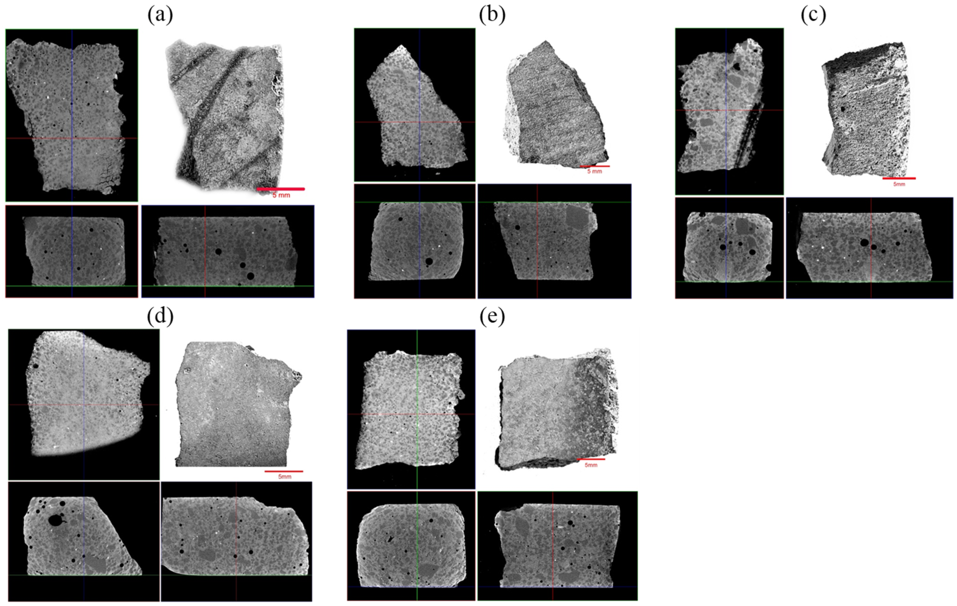
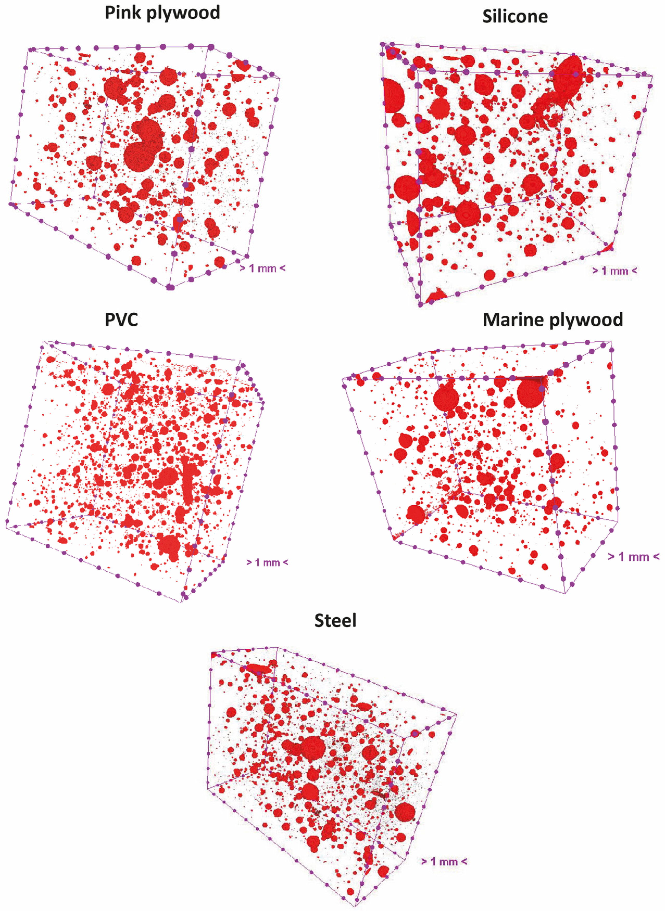
Figure 1 arranges in a Cartesian plane the images resulting from X-ray μCT of the concrete surfaces cast within the various formwork materials; a photographic image of each specimen was inserted in the upper right region. X-ray μCT showed that different densities were found over the area of the concrete’s surface. For example, regions with a higher density and lower porosity values may have cement products with a higher hydration degree [40]. Moreover, decreases in the permeability of cement pastes were expected during hydration [41].
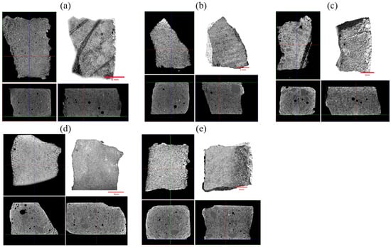
Figure 1.
X-ray Microtomography (μCT) from the surface of concrete specimens cast within different formwork materials: (a) Galvanized steel; (b) Marine plywood; (c) Regular plywood (pink); (d) Silicone; (e) PVC. Red line in the upper right figure represents a dimension of 5 mm.
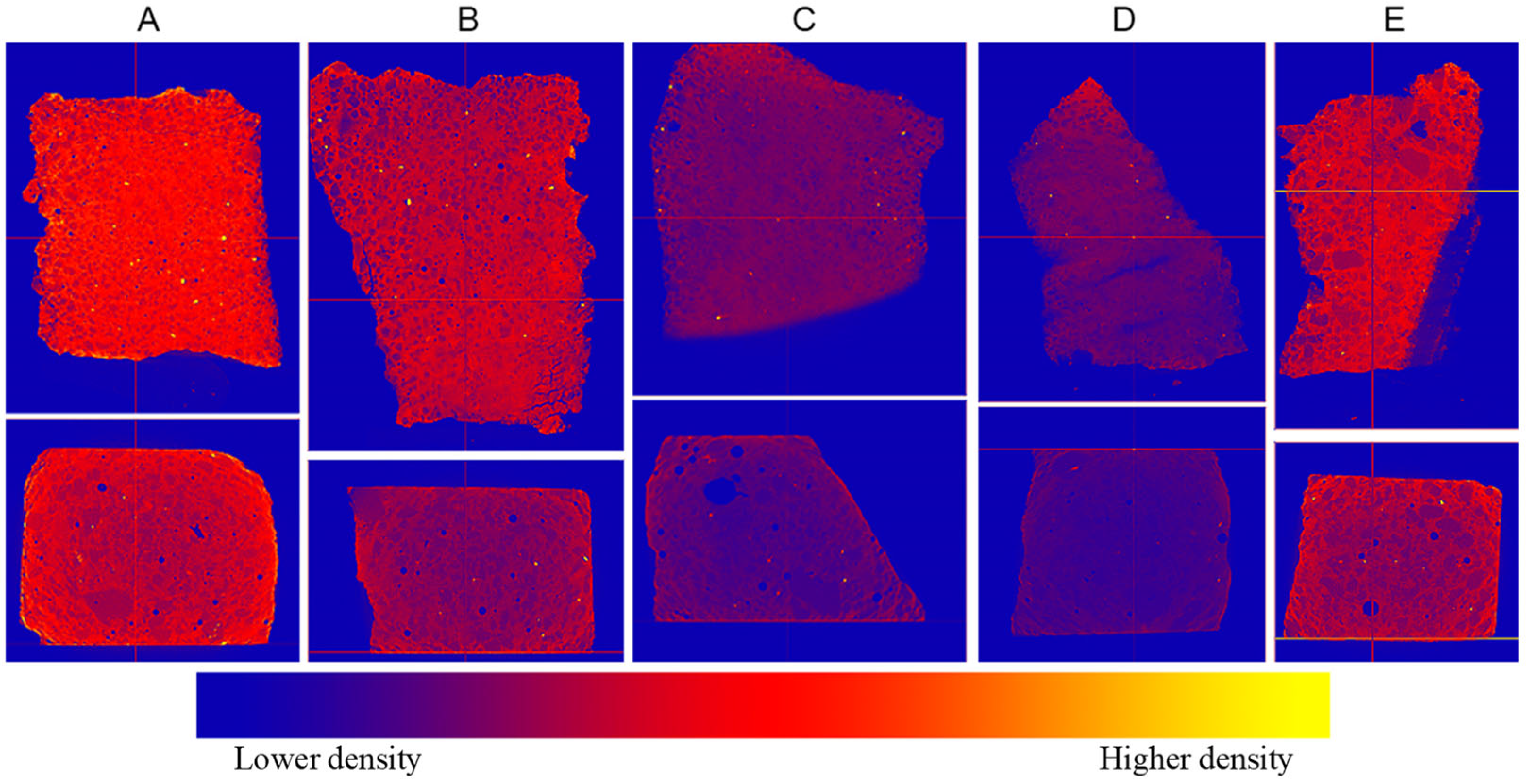
Figure 2 further explores the density difference over the concrete surface produced with the distinct formwork. The results indicate that PVC formwork led to higher surface density. Galvanized steel and regular plywood (pink) resulted in intermediate density values, whereas silicone and marine plywood were responsible for the lowest surface densities. Figure 2 shows less uniformity of densities on the concrete surfaces produced in contact with galvanized steel and marine plywood since several areas have different shades. In contrast, concrete surface densities were more uniform for the other formwork materials.
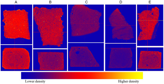
Figure 2.
Densities of concrete along the surface (top) and front view (bottom), regarding specimens cast on different formwork materials: (A)—PVC; (B)—Galvanized Steel; (C)—Silicone; (D)—Marine plywood; (E)—Regular plywood (pink).
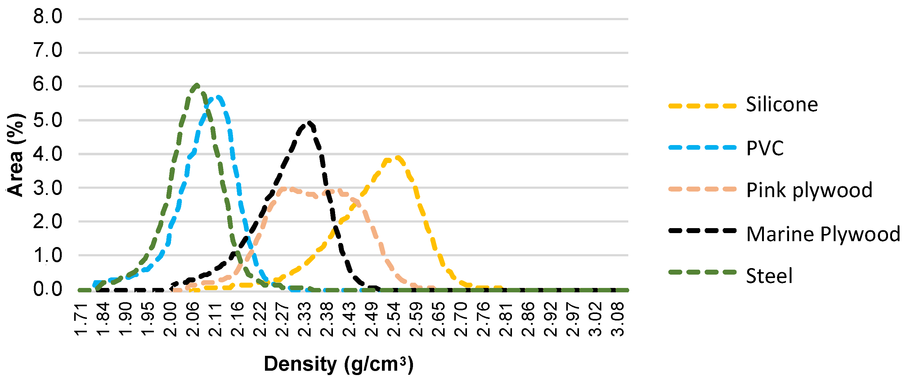
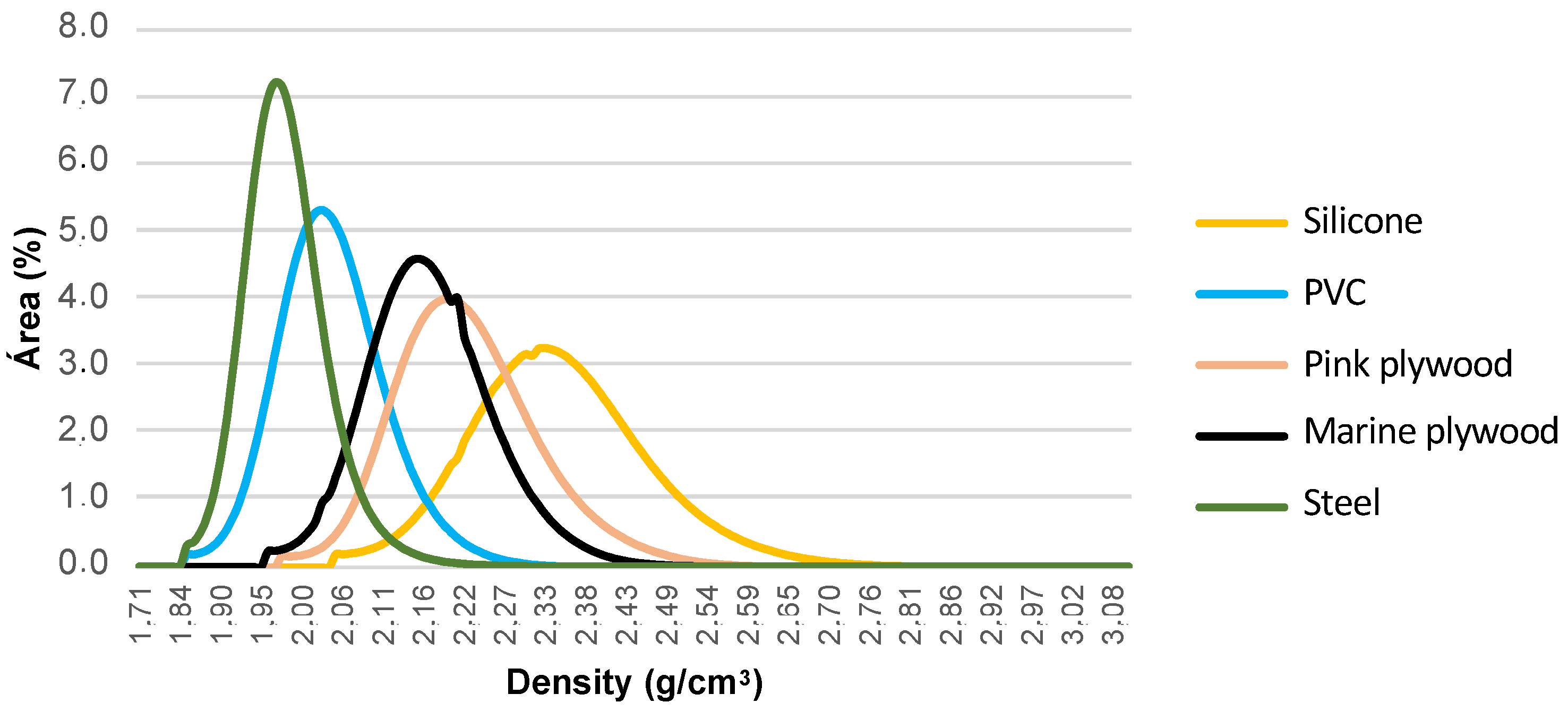
Figure 3 and Figure 4 compare the densities of the concrete in normal distribution graphs regarding the external surface layer and the total volume of the tested specimens, respectively. When comparing the graphs, it is observed that all concrete surfaces molded with different formwork materials presented higher surface densities when compared to the total volume density of the sample. This difference is substantial for concrete surfaces molded using silicone and marine plywood formwork. This result may indicate that in the concrete-form interface region, there may have been a greater tendency for cement hydration [38]. The surface-densified microstructure may be due to additional calcium silicate hydrates (C-S-H) formation [42]; higher densities can mitigate chloride diffusivity, mainly if associated with an enhanced chloride binding capacity [43].
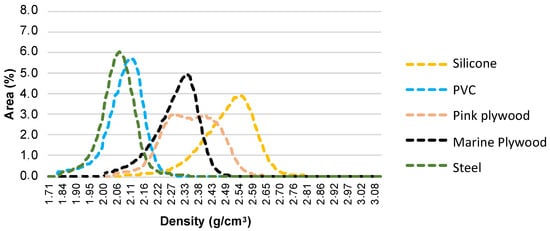
Figure 3.
Densities of the surface layer of concrete specimens molded within different formwork materials.
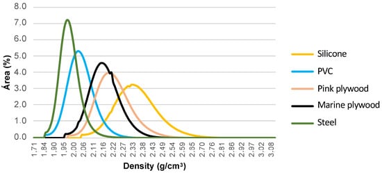
Figure 4.
Densities of the total volume of the tested concrete specimens molded within different formwork materials.
The concrete X-ray μCT enabled the quantification of the pore volume of the analyzed specimens, as shown in Table 4 and Figure 5, and the visualization of their dimensions and distribution. Specimens produced with silicone and marine plywood formworks had similar pore volumes, but silicone led to larger surface pores than marine plywood. The concrete cast with PVC formwork had much higher pore volume but relatively small pore sizes. The specimens produced with galvanized steel and regular plywood (pink) had similar porosity regarding pore volume, size, and distribution.
Table 4.
Concrete porosity and mean density of the specimens’ total volume or surface layer.
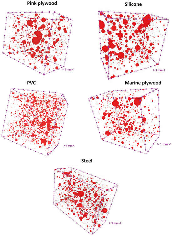
Figure 5.
Pore distribution in concrete specimens molded within different formwork materials.
3.2. Concrete Surface Voids Assessed with SEM
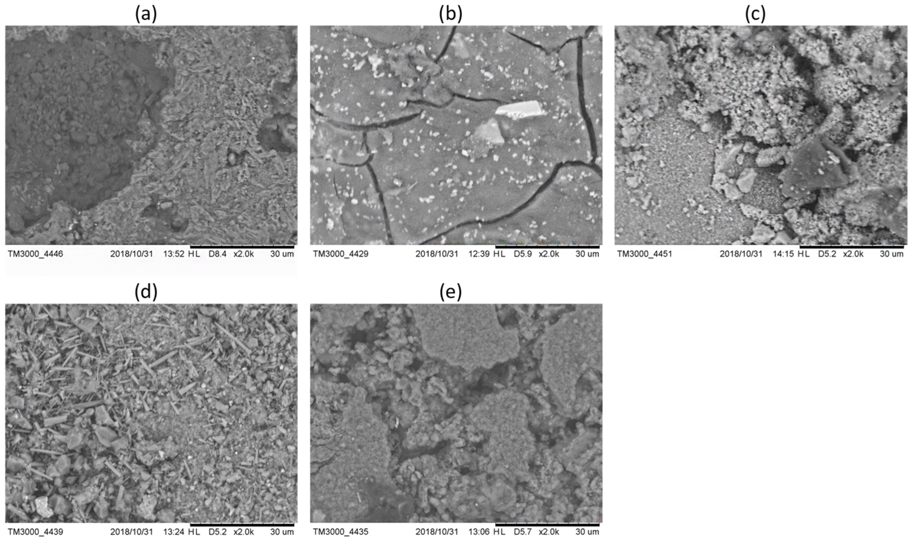
Figure 6 shows the SEM images of the concrete surfaces cast within the different formwork materials at 2000 times magnification, illustrating distinct microscopic morphological formations. SEM images had shades from white to black with several gray tones. According to Monteiro et al. [44], anhydrous cement grains should have the lightest coloration, as should calcium hydroxide (Ca(OH)2), which should present a light gray tone; a dark gray tone is expected from C-S-H and voids are black. Especially in Figure 6a,c,e, C-S-H may be verified as an amorphous, fibrous structure in the darker gray regions, while voids appear as black areas scattered throughout the image. Figure 6b potentially displays light gray crystals typical of Ca(OH)2 with dark cracks representing voids.

Figure 6.
Scanning Electronic Microscopy (SEM) with secondary electrons of the concrete cast within different formwork materials. 2000 times magnification and 30 µm scale. Concrete produced within: (a) Galvanized steel; (b) Marine plywood; (c) Regular plywood (pink); (d) Silicone; (e) PVC.
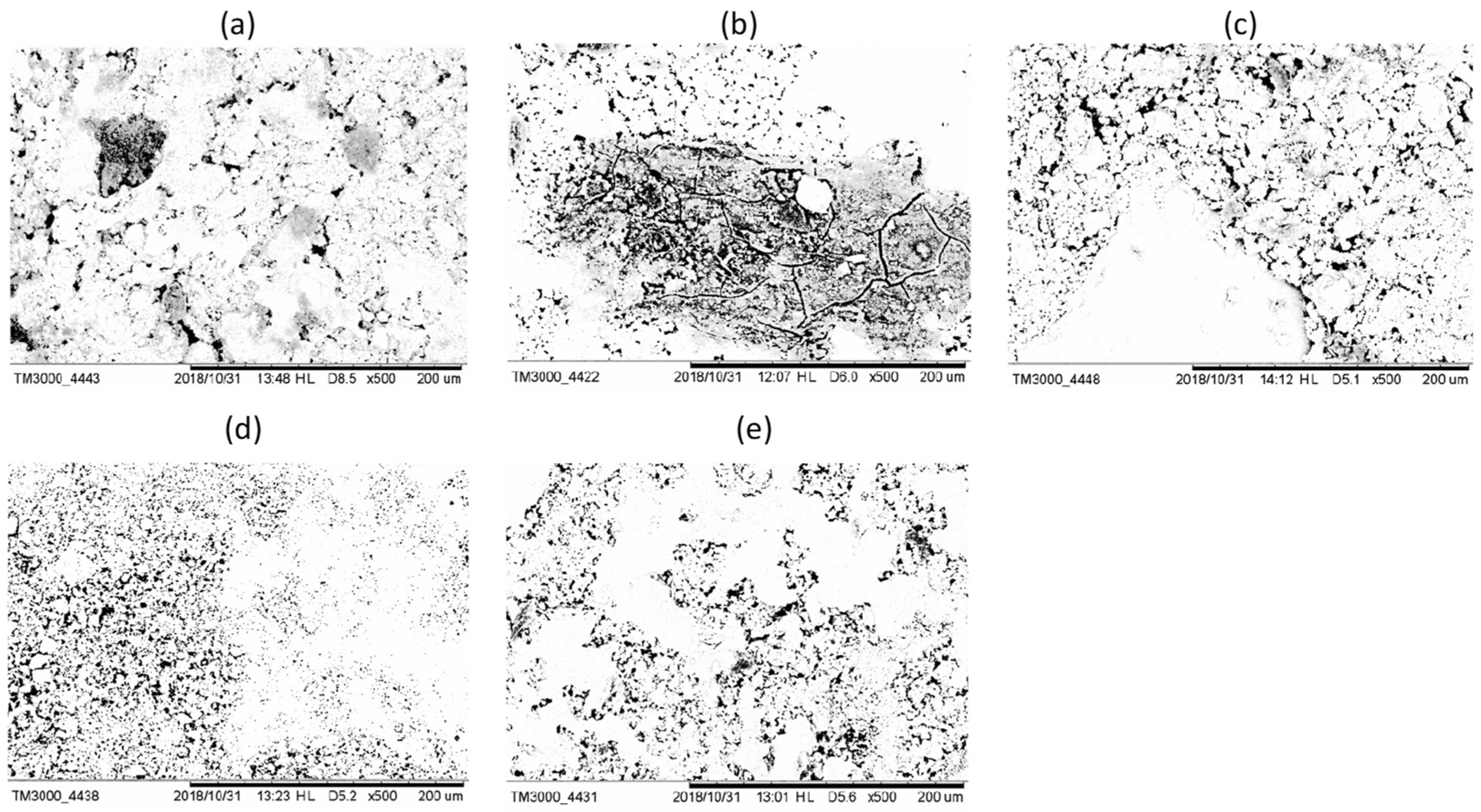
The voids on the specimens’ surface were quantified from the SEM images by selecting the black shades. Table 5 presents the ratio between the voids and the total evaluated area, while Table 6 shows the frequency of void sizes observed during the treatment of the images. Figure 7 further illustrates the treatment of images with black and white shades, and finally, Figure 8 presents a relative frequency distribution of the void sizes observed in the concrete surfaces.
Table 5.
Ratio between the voids and the total evaluated area of the specimens, with images at 200 µm scale.
Table 6.
Void sizes observed on the concrete surface cast within different formwork materials. Caption: Occ = Occurrence; Acc—Accumulated.

Figure 7.
Scanning Electronic Microscopy (SEM) with secondary electrons of the concrete cast on different formwork materials. 500 times magnification and 200 µm scale. Black and white comparison for concrete produced within: (a) Galvanized steel; (b) Marine plywood; (c) Regular plywood (pink); (d) Silicone; (e) PVC.
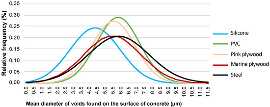
Figure 8.
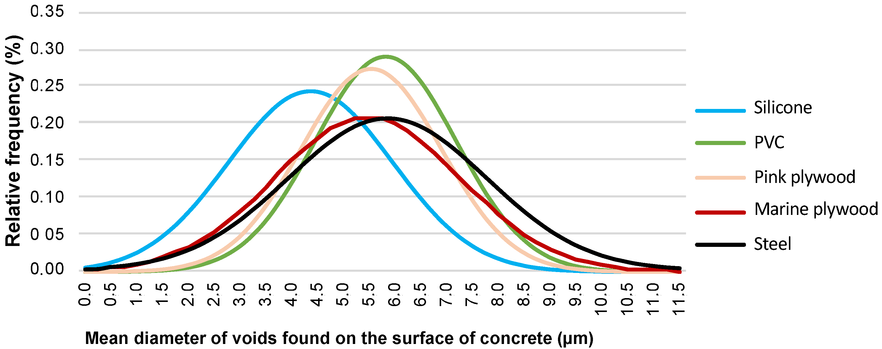
Relative frequency distribution of the void sizes in the concrete surfaces cast within different formwork materials.
The surface of concrete specimens produced with marine plywood formwork had the highest void content within the total evaluated area, with almost 3.5 times more voids than the surface resulting from galvanized steel formwork, as seen in Table 5. Regular pink plywood and PVC led to similar results concerning the area of surface voids and the most recurrent void size, with the highest quantity observed being around 6.0 µm. According to Figure 8, although galvanized steel and marine plywood formworks had many voids with around 6.0 µm, they also had more voids distributed from 2.5 µm to 9.5 µm compared to regular plywood and PVC. In the distribution of the void sizes, silicone formwork led to the most particular behavior, with it concentrating almost 25% in smaller sizes around 4.0 µm.
3.3. Elementary Chemical Analysis Through EDS
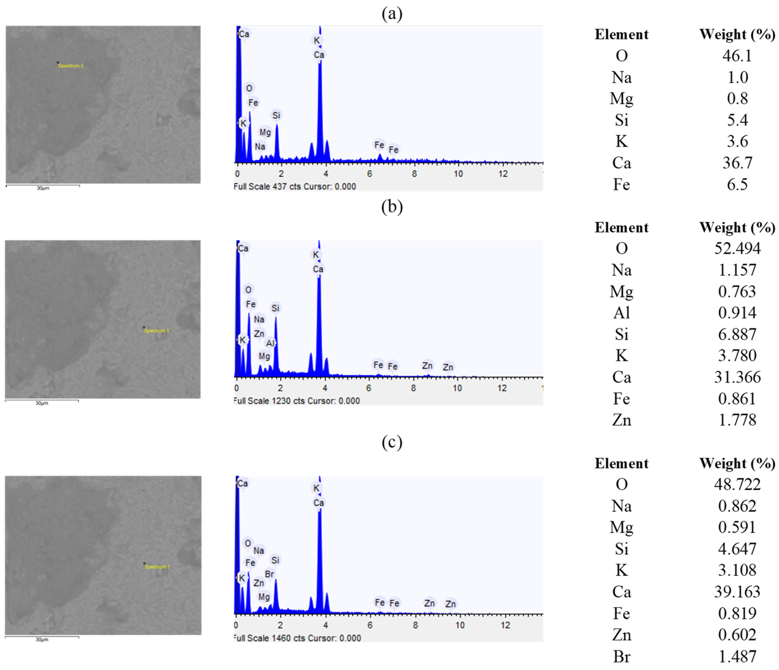
Concerning EDS, evaluated in association with SEM, Figure 9 depicts the results of the concrete surface cast within galvanized steel formwork. Firstly, Figure 9a refers to the darkest shade observed in the specimen, indicating the probable presence of tetracalcium aluminoferrate (C4FH). The C4FH phase is a solid solution oscillating between C2F and C6A2F [45]. The spectrum in Figure 9b highlights the presence of zinc (Zn). Since the steel used as formwork receives a thin layer of Zn for galvanization to protect it against corrosion, the Zn may have reacted with the other cement products. Lastly, Figure 9c shows, as well as Zn, the occurrence of bromine (Br). Br may be present in drinking water, as it is an agent similar to chlorine (Cl) in the water disinfection process [46]. However, Br is an aggressive agent for steel corrosion, in addition to it potentially causing the decomposition of C-S-H and other harmful reactions [47].
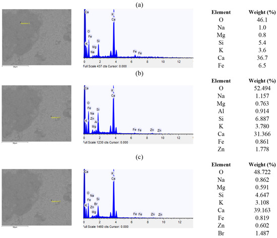
Figure 9.
Energy Dispersive X-ray Spectroscopy (EDS) spectrum of the concrete surface cast within galvanized steel: (a) Darkest shade observed in the specimen; (b) Presence of zinc (Zn); (c) Presence of bromine (Br).
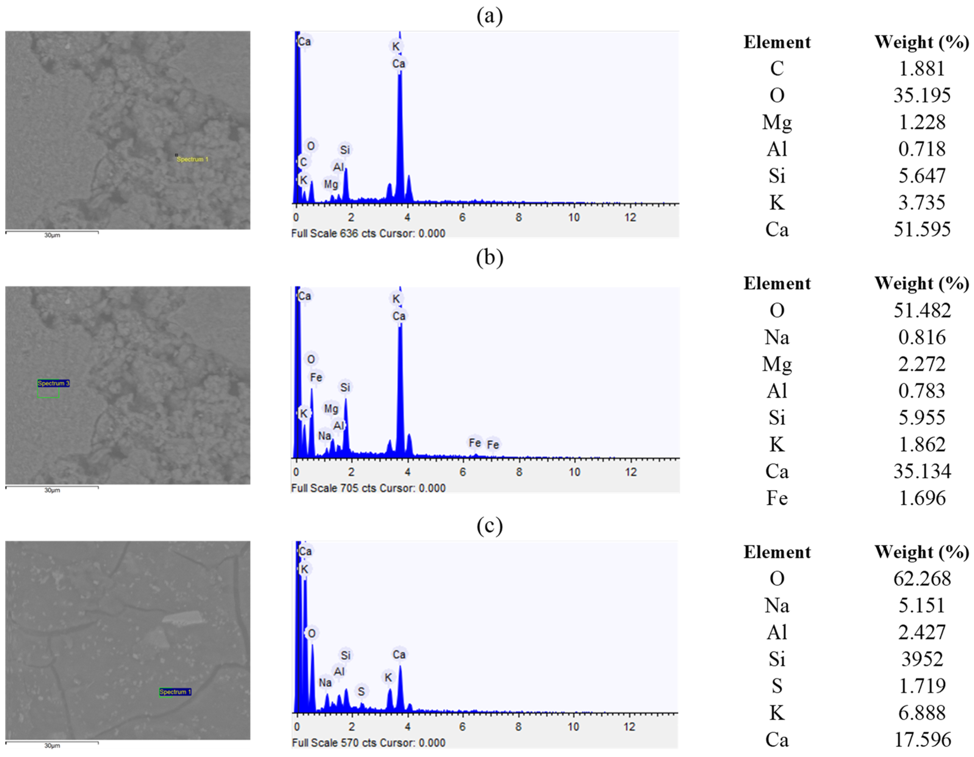
Figure 10 shows the spectrum for the concrete surface obtained with marine plywood formwork. Figure 10a relates to rounded crystals, demonstrating an elevated presence of calcium (Ca) and oxygen (O). Also, the presence of carbon (C) stood out as C modifies the chemical stability of concrete, leading to carbonation. According to Matschei et al. [48], many carbonate sources bonded to concrete are not evident in this context. C is the main element in phenolic resins present in both marine and regular plywood, potentially transferring C to the concrete surfaces. Regarding chemical resistance, phenolic resins tend to have questionable behavior when in contact with alkaline solutions [49], such as Portland cementitious products [50]. On the other hand, carbonated concrete is more resistant and less permeable to aggressive agents’ penetration than non-carbonated concrete [51], thus suggesting potential benefits from the C migration from the mold to the concrete surface.
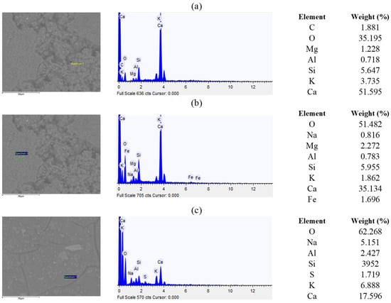
Figure 10.
Energy Dispersive X-ray Spectroscopy (EDS) spectrum of the concrete surface cast within marine plywood: (a) Rounded crystals; (b) Less rough region; (c) Darkest shade observed in the specimen.
Figure 10b depicts a spectrum formed on the less rough region of the concrete surface molded with marine plywood, possibly containing tricalcium silicate or alite (C3S) due to the observed amounts of O, Ca, and silicon (Si). In the case of C3S silicates, small amounts of ions (magnesium (Mg), aluminum (Al), iron (Fe), potassium (K), sodium (Na), and sulfur (S)) occur [52]. Mg contents above 2% can crystallize as periclase, which has slow hydration and can increase in volume over the years, causing internal tensions. On the other hand, Mg ions may react with the cement mortar, forming a magnesium hydroxide film over the substrate, preventing sulfate ions from entering [53]. The occurrence of alkalis, K and Na, can affect the cement’s setting time, accelerating it and impacting mechanical strength development [54].
The darkest shade of the specimen shown in Figure 10c had different chemical and morphological characteristics. K and Na alkalis were also present, and the incidence of Na may reinforce the hypothesis of the migration of phenolic resin elements to the concrete surface, as the most commonly used catalysts during the curing process of these resins are sodium hydroxide (NaOH), potassium hydroxide (KOH), ammonia (NH3), sodium carbonate (Na2CO3), and hydrogen chloride (HCl) [55]. Cracking is noticed in Figure 10c.
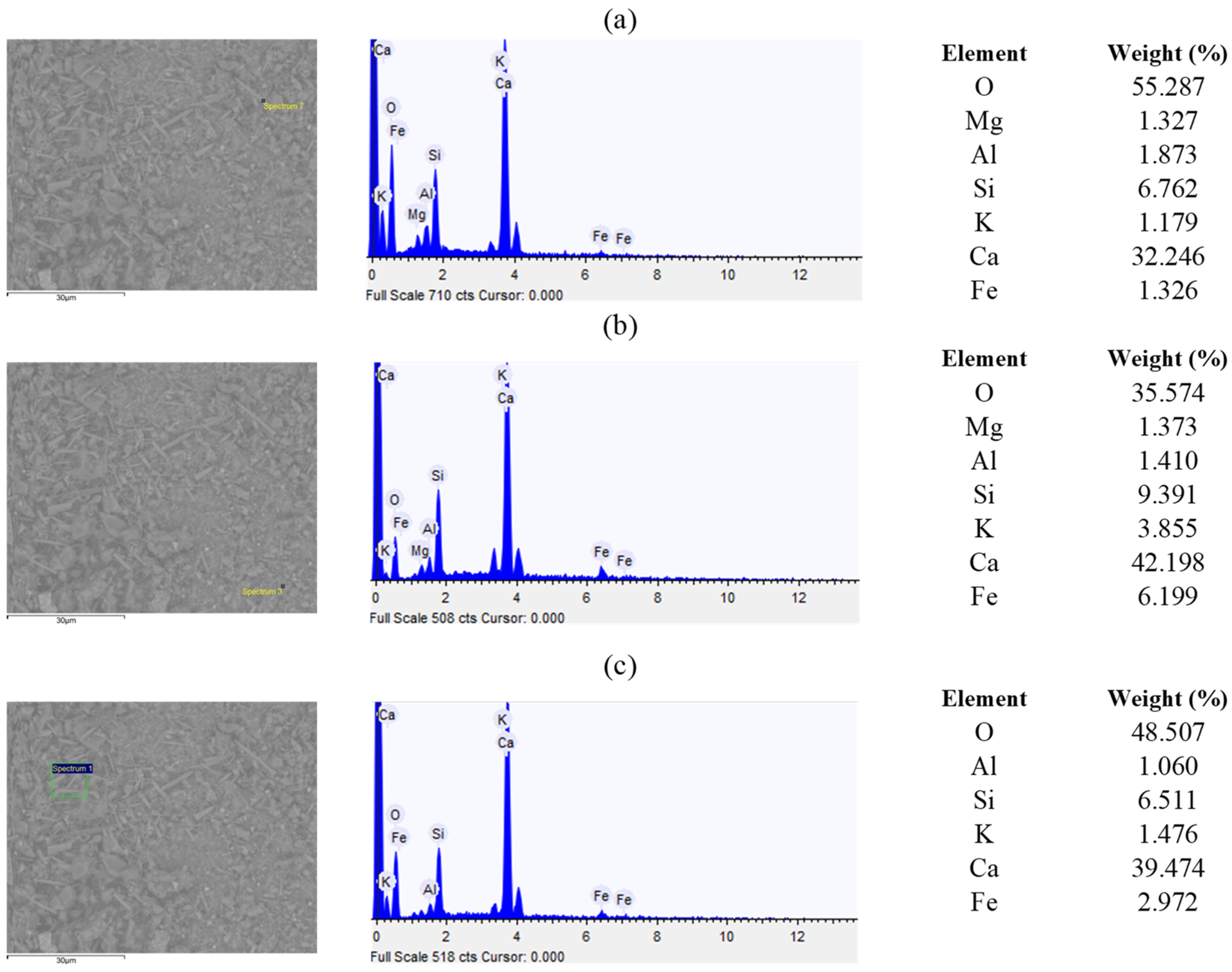
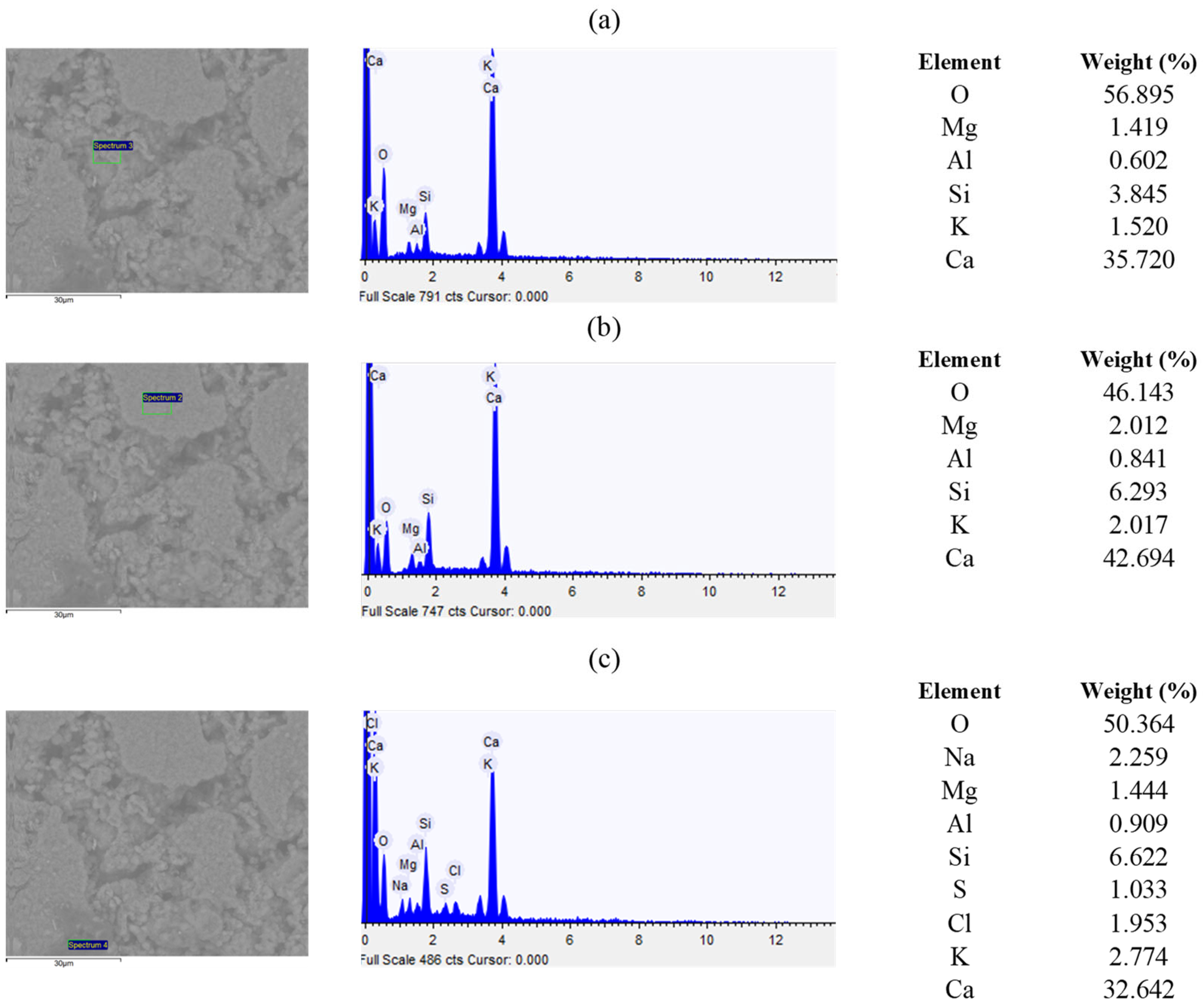
Figure 11 shows the EDS spectra for the concrete surface molded on regular pink plywood. The chemical elements in Figure 11a probably compose the AFm phase within concrete hydration. The presence of alkalis was also identified. C and Fe, shown in Figure 11b, can lead to the formation of iron carbonate (FeCO3), which is responsible for concrete degradation and the appearance of brown stains on its surface [56]. Regarding Figure 11, Na and C are probably derived from the formwork, which, similarly to the marine plywood, also receives a phenolic resin. According to Zhao et al. [57], chlorides can degrade the concrete in the presence of sulfates, decreasing strength in the initial ages and causing volume expansion, loss of mass, visual damage, and detachment of fragments.
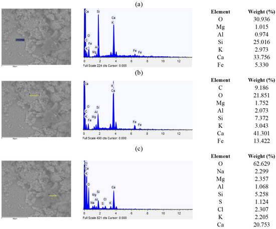
Figure 11.
Energy Dispersive X-ray Spectroscopy (EDS) spectrum of the concrete surface cast within regular plywood (pink): (a) Less rough region; (b,c) Rougher regions.
EDS analysis of the concrete produced with silicone formwork is presented in Figure 12. In this case, the chemical compositions along the three spectra of the specimens remained similar, with no particular occurrences within the subfigures (Figure 12a–c), which have all shown mainly O, Ca, and Si with the highest amounts. Unlike other formwork materials, silicone can have a lower chemical reactivity [58], and, probably because of that, the resulting concrete surfaces showed fewer impurities or migrations.
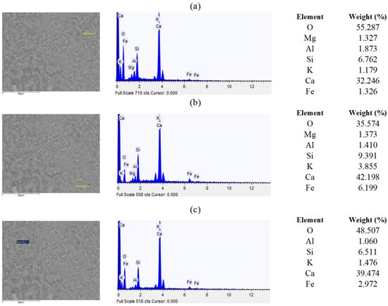
Figure 12.
Energy Dispersive X-ray Spectroscopy (EDS) spectra of the concrete surface cast within silicone.
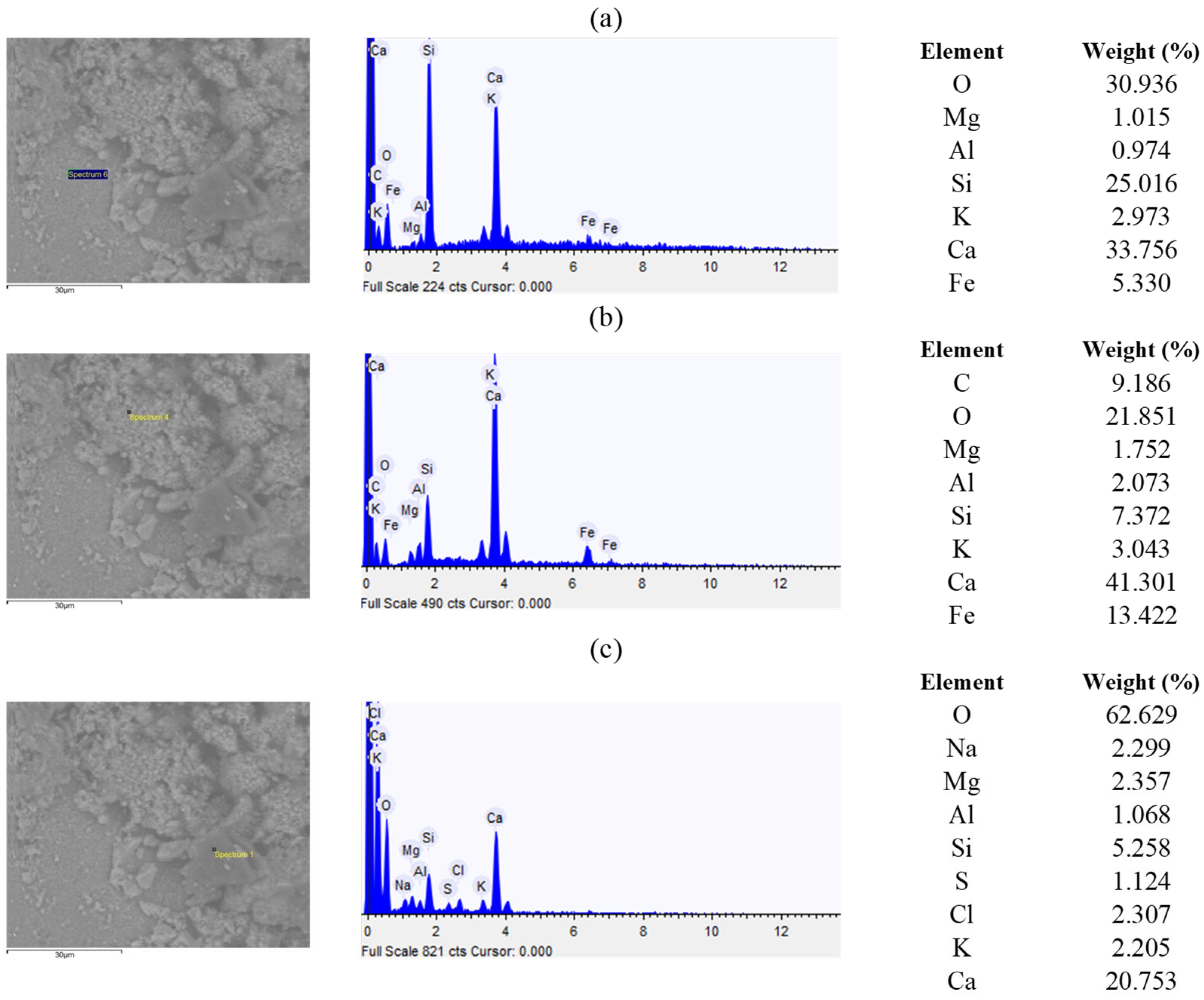
Finally, EDS analysis for concrete produced with PVC formwork showed different chemical elements on the surface of the specimens. Figure 13a depicts the spectrum formed over rounded crystals with a high concentration of Ca and O. Then, Figure 13b illustrates a less rough area with a high value of Mg. Lastly, Figure 13c shows the spectrum formed on the darker crystals of the concrete surface, which had relevant amounts of Ca, O, and Si.
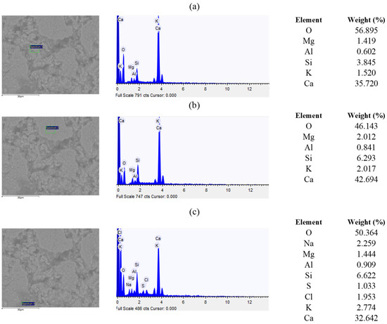
Figure 13.
Energy Dispersive X-ray Spectroscopy (EDS) spectrum of the concrete surface cast within PVC: (a) Rounded crystals; (b) Less rough region; (c) Darker crystals.
The presence of Cl on the concrete surface, identified in Figure 13c, could be due to the composition of PVC (polyvinyl chloride). PVC, generally, has satisfactory chemical resistance to alkalis at temperatures up to 60 °C [59]. However, the temperature may reach values above 70 °C during cement hydration, mainly for CP V-ARI [60]. Therefore, PVC components could have been transferred to the concrete surface during hydration and temperature increase. Concrete with Cl is susceptible to cracks caused by increased chlorine volume during crystallization [61]; the tensile forces from crystal expansion can likely affect the adherence of additional external coatings.
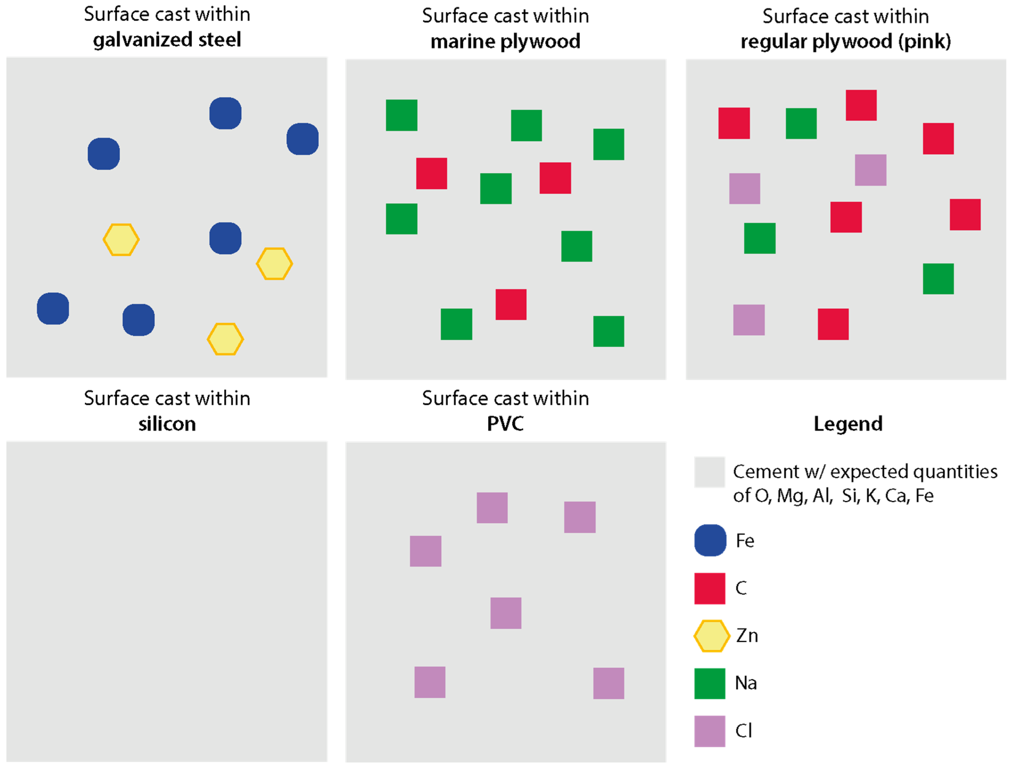
Figure 14 presents a visual schematic demonstrating the chemical elements found on the concrete surfaces that may have originated from contact with the formwork during casting. This scheme was developed by comparing the chemical elements from the formworks (Table 2) with those conventionally found in concrete, according to the composition of Portland cement as described by Neville [62] (CaO: 60–67%; SiO2: 17–25%; Al2O3: 3–8%; Fe2O3: 0.5–6.0%; SO3: 1–3%; MgO: 0.1–4.0%; Alkalis K2O, Na2O: 0.2–1.3%). Thus, the scheme highlights the chemical elements that likely originated from the formworks and which are not part of the standard composition of the cement or that were found in large quantities on the surface of the concrete.
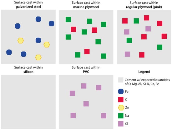
Figure 14.
Visual diagram demonstrating the chemical elements that may have migrated from the formwork to the concrete surface.
3.4. General Overview
PVC formwork led to a concrete surface with high density and relatively small pore sizes. Based on Liu et al. [10], the absence of visible defects on the surface, with reduced mesopores and improved pore structures, may restrain water absorption, contributing to durability, which is especially important considering the identified migration of chloride from the formwork to the concrete.
Galvanized steel and regular plywood (pink) had similar results, leading to intermediate density values with similar pore volumes, sizes, and distribution. Silicone and marine plywood were responsible for the lowest surface densities, with similar pore volumes. However, silicone led to larger surface pores than marine plywood in µCT, although it concentrated almost 25% in smaller sizes around 4.0 µm.
Regular and marine plywood presented sodium distributed throughout their surface, while galvanized steel showed iron and zinc. Additionally, marine plywood formwork resulted in the highest void content; increasing void ratio could be related to decreasing interlayer strength [13], potentially implicating the concrete performance after casting. A general finding is that surface densities were higher than the specimen’s total volume density independent of the formwork material.
4. Conclusions
This research approached the surface quality of concrete produced within different formwork materials, including galvanized steel, regular plywood (pink), marine plywood, polyvinyl chloride (PVC), and silicone. With X-ray μCT, SEM, and EDS, discussions addressed surface density, porosity, voids, and chemical elementary composition. With the results obtained, it is possible to highlight the following main findings:
- The formwork material influenced the surface density of concrete. PVC led to the highest surface density, and silicone and marine plywood to the lowest;
- The external surface layer of the concrete had a higher density than the rest of the tested specimens’ volume;
- Silicone and marine plywood formworks led to similar pore volumes on the concrete surface, but the first resulted in larger surface pores than the latter. PVC formwork was responsible for a much higher pore volume, and galvanized steel and regular plywood (pink) had similar porosity;
- The concrete surface cast within different formwork materials had distinct microscopic morphology;
- Marine plywood led to the highest content of surface voids in the evaluated area. Regular plywood and PVC led to similar surface concrete voids, mostly around 6.0 µm. Silicone formwork led to the most particular behavior, concentrating most of the voids in smaller sizes around 4.0 µm;
- Some chemical elements from the formwork materials migrated to the concrete surface. Specimens molded within steel presented Zn, while Cl was found on the surface molded with PVC, and C and Na were present in surfaces produced with regular pink and marine plywood.
Therefore, this research confirmed the influence of formwork materials on the surface quality of concrete, supporting decision-making for different types of construction work. For example, silicone molds could be interesting for apparent concrete surfaces due to their smaller surface voids. However, PVC also has the advantage, in this case, of a higher surface density. On the other hand, for concretes receiving additional coating layers, the surface quality is paramount regarding performance, so adhesion tests are recommended to understand the adequate formwork for each coating composition.
The topic is important because it is related to durability and performance concerns. Furthermore, the impact of formwork extends to adherence properties in the case of additional coating layers. Additional research may be suggested regarding the effects of formwork on other surface phenomena or more sustainable concrete mixings, such as including bio-based materials.
Author Contributions
Conceptualization, S.T.H.D. and A.B.M.; Data curation, S.T.H.D. and A.B.M.; Formal analysis, S.T.H.D.; Funding acquisition, A.B.M.; Investigation, S.T.H.D.; Methodology, S.T.H.D. and A.B.M.; Resources, A.B.M.; Software, S.T.H.D.; Supervision, A.B.M.; Visualization, S.T.H.D.; Writing—original draft, S.T.H.D., J.D.B. and A.B.M.; Writing—review and editing, S.T.H.D., J.D.B. and A.B.M. All authors have read and agreed to the published version of the manuscript.
Funding
This research was funded by CNPq (Conselho Nacional de Desenvolvimento Científico e Tecnológico) and CAPES (Coordenação de Aperfeiçoamento de Pessoal de Nível Superior). The second author acknowledges the Foundation for Science and Technology’s (FCT) support through funding UIDB/04625/2020 from the research unit CERIS (DOI: 10.54499/UIDB/04625/2020) and the grant number 2023.05316.BD (DOI: 10.54499/2023.05316.BD).
Data Availability Statement
The original contributions presented in the study are included in the article; further inquiries can be directed to the corresponding author.
Acknowledgments
The authors appreciate the support of LAMTAC (Laboratório de Materiais e Tecnologia do Ambiente Construído), PPGCI (Programa de Pós-Graduação em Engenharia Civil: Construção e Infraestrutura), UFRGS (Universidade Federal do Rio Grande do Sul), CNPq (Conselho Nacional de Desenvolvimento Científico e Tecnológico) and CAPES (Coordenação de Aperfeiçoamento de Pessoal de Nível Superior).
Conflicts of Interest
The authors declare no conflicts of interest. The funders had no role in the design of the study; in the collection, analyses, or interpretation of data; in the writing of the manuscript; or in the decision to publish the results.
References
- Sadowski, Ł.; Mathia, T.G. Multi-Scale Metrology of Concrete Surface Morphology: Fundamentals and Specificity. Constr. Build. Mater. 2016, 113, 613–621. [Google Scholar] [CrossRef]
- Alexander, M.G.; Ballim, Y.; Stanish, K. A Framework for Use of Durability Indexes in Performance-Based Design and Specifications for Reinforced Concrete Structures. Mater. Struct. Mater. Constr. 2008, 41, 921–936. [Google Scholar] [CrossRef]
- Pan, Y.; Zhang, Y.; Zhang, D.; Yang, H. Effect of Polymer and Conventional Molds on the Aesthetical Surface Quality of Concretes. Constr. Build. Mater. 2021, 302, 124375. [Google Scholar] [CrossRef]
- Peng, L.; Shen, P.; Poon, C.S.; Zhao, Y.; Wang, F. Development of Carbon Capture Coating to Improve the Durability of Concrete Structures. Cem. Concr. Res. 2023, 168, 107154. [Google Scholar] [CrossRef]
- He, J.; Qiao, C.; Farnam, Y. Durability Evaluation of Reinforced Concrete with Surface Treatment of Soy Methyl Ester-Polystyrene under Freeze-Thaw Cycles and Calcium Chloride. Cem. Concr. Compos. 2023, 137, 104927. [Google Scholar] [CrossRef]
- Chen, C.; Liu, J.; Cui, G.; Liu, J. Effect of Controlled Permeable Formwork on the Improvement of Concrete Performances. Procedia Eng. 2012, 27, 405–411. [Google Scholar] [CrossRef]
- Suryavanshi, A.K.; Swamy, R.N. An Evaluation of Controlled Permeability Formwork for Long-Term Durability of Structural Concrete Elements. Cem. Concr. Res. 1997, 27, 1047–1060. [Google Scholar] [CrossRef]
- Tichko, S.; Van De Maele, J.; Vanmassenhove, N.; De Schutter, G.; Vierendeels, J.; Verhoeven, R.; Troch, P. Numerical Simulation of Formwork Pressure While Pumping Self-Compacting Concrete Bottom-Up. Eng. Struct. 2014, 70, 218–233. [Google Scholar] [CrossRef]
- Libessart, L.; De Caro, P.; Djelal, C.; Dubois, I. Correlation between Adhesion Energy of Release Agents on the Formwork and Demoulding Performances. Constr. Build. Mater. 2015, 76, 130–139. [Google Scholar] [CrossRef]
- Liu, J.; Miao, C.; Chen, C.; Liu, J.; Cui, G. Effect and Mechanism of Controlled Permeable Formwork on Concrete Water Adsorption. Constr. Build. Mater. 2013, 39, 129–133. [Google Scholar] [CrossRef]
- Qian, C.; Liu, Q.; Zhang, J.; Zhou, Z. Influence of Materials and Processes on the Robustness of Apparent Porosity Control Methods for Fair-Faced Concrete. J. Build. Eng. 2024, 94, 109956. [Google Scholar] [CrossRef]
- Sadowski, Ł.; Stefaniuk, D. The Effect of Surface Treatment on the Microstructure of the Skin of Concrete. Appl. Surf. Sci. 2018, 427, 934–941. [Google Scholar] [CrossRef]
- He, L.; Chen, B.; Liu, Q.; Chen, H.; Li, H.; Chow, W.T.; Tang, J.; Du, Z.; He, Y.; Pan, J. A Quasi-Exponential Distribution of Interfacial Voids and Its Effect on the Interlayer Strength of 3D Printed Concrete. Addit. Manuf. 2024, 89, 104296. [Google Scholar] [CrossRef]
- Lim, M.K.; Nam, K.Y. Comparative Analysis on the Micropore and Microstructure Characteristics of Concrete under Insulated Formwork. Materials 2021, 14, 2862. [Google Scholar] [CrossRef]
- Jiang, Q.; Yu, C.; Zhou, M. Effect of Typical Formworks and Release Agents on Aesthetical Surface Quality of Concrete. Mag. Concr. Res. 2023, 75, 1285–1296. [Google Scholar] [CrossRef]
- Mohseni, S.H.; Bahij, S.; Omary, S.; Feugeas, F.; Birinci, F. Effect of Formwork Surface Texture Features on Surface Morphology, Roughness Parameters, and the Demolding Force of Cementitious Materials. J. Civ. Environ. Eng. 2022, 12, 449. [Google Scholar] [CrossRef]
- Deboodt, T.; Wildenschild, D.; Ideker, J.H.; Burkan Isgor, O. Comparison of Thresholding Techniques for Quantifying Portland Cement Hydrates Using Synchrotron Microtomography. Constr. Build. Mater. 2021, 266, 121109. [Google Scholar] [CrossRef]
- Luo, Y.; Yu, Q. Valorization of Mineral Wool Waste in Class F Fly Ash Geopolymer: Geopolymerization, Macro Properties, and High Temperature Behavior. Cem. Concr. Compos. 2024, 145, 105318. [Google Scholar] [CrossRef]
- Xu, K.; Tremsin, A.S.; Li, J.; Ushizima, D.M.; Davy, C.A.; Bouterf, A.; Su, Y.T.; Marroccoli, M.; Mauro, A.M.; Osanna, M.; et al. Microstructure and Water Absorption of Ancient Concrete from Pompeii: An Integrated Synchrotron Microtomography and Neutron Radiography Characterization. Cem. Concr. Res. 2021, 139, 106282. [Google Scholar] [CrossRef]
- Xu, K.; Jin, Q.; Li, J.; Ushizima, D.M.; Li, V.C.; Kurtis, K.E.; Monteiro, P.J.M. In-Situ Microtomography Image Segmentation for Characterizing Strain-Hardening Cementitious Composites Under Tension Using Machine Learning. Cem. Concr. Res. 2023, 169, 107164. [Google Scholar] [CrossRef]
- Saha, S.K.; Pradhan, S.; Barai, S.V. Use of Machine Learning Based Technique to X-Ray Microtomographic Images of Concrete for Phase Segmentation at Meso-Scale. Constr. Build. Mater. 2020, 249, 118744. [Google Scholar] [CrossRef]
- Li, F.; Chen, Q.; Lu, Y.; Zou, Y.; Li, S. Mitigating Drying Shrinkage and Enhancing Mechanical Strength of Fly Ash-Based Geopolymer Paste with Functionalized MWCNTs Grafted with Silane Coupling Agent. Cem. Concr. Compos. 2023, 143, 105250. [Google Scholar] [CrossRef]
- Mehta, P.K.; Monteiro, P.J.M. Cimentos Hidráulicos. In Concreto, Microestrutura, Propriedades E Materiais; Hasparyk, N.P., Ed.; IBRACON: São Paulo, Brazil, 2014; pp. 215–273. [Google Scholar]
- ABNT NBR 16697:2018; Portland cement—Requirements. ABNT—Associação Brasileira de Normas Técnicas: Rio de Janeiro, Brazil, 2018.
- ABNT NBR NM 23; Cimento Portland e Outros Materiais Em Pó—Determinação Da Massa Específica. ABNT—Associação Brasileira de Normas Técnicas: Rio de Janeiro, Brazil, 2000.
- ABNT NBR 16607; Portland Cement—Determination of Setting Times. ABNT—Associação Brasileira de Normas Técnicas: Rio de Janeiro, Brazil, 2018.
- ABNT NBR 7215; Portland Cement—Determination of Compressive Strength of Cylindrical Test Specimens. ABNT—Associação Brasileira de Normas Técnicas: Rio de Janeiro, Brazil, 2019.
- Li, W.; Lin, X.; Bao, D.W.; Min Xie, Y. A Review of Formwork Systems for Modern Concrete Construction. Structures 2022, 38, 52–63. [Google Scholar] [CrossRef]
- Callister, W.D.; Rethwisch, D.G. Ciência e Engenharia de Materiais—Uma Introdução, 9th ed.; LTC: Rio de Janeiro, Brazil, 2016. [Google Scholar]
- Pizzi, A.; Mittal, K.L. Handbook of Adhesive Technology; Marcell Deckker: New York, NY, USA, 1994. [Google Scholar]
- Kumar, A.; Gupta, R.K. Fundamentals of Polymers Engineering; Marcel Dekker: New York, NY, USA, 2003. [Google Scholar]
- Helene, P.; Terzian, P. Manual de Dosagem e Controle Do Concreto; Pini: São Paulo, Brazil, 1993. [Google Scholar]
- ABNT NBR 16889; Fresh Concrete—Slump Test. ABNT—Associação Brasileira de Normas Técnicas: Rio de Janeiro, Brazil, 2020.
- ABNT NBR 5739; Concrete—Compression Strength of Cylindrical Specimens. ABNT—Associação Brasileira de Normas Técnicas: Rio de Janeiro, Brazil, 2018.
- Bruker. Microtomography—Welcome to Bruker MicroCT. Available online: https://www.bruker.com/products/microtomography.html (accessed on 15 November 2018).
- Razi, T.; Niknami, M.; Alavi Ghazani, F. Relationship between Hounsfield Unit in CT Scan and Gray Scale in CBCT. J. Dent. Res. Dent. Clin. Dent. Prospect. 2014, 8, 107–110. [Google Scholar] [CrossRef]
- Schneider, U.; Pedroni, E.; Lomax, A. The Calibration of CT Hounsfield Units for Radiotherapy Treatment Planning. Phys. Med. Biol. 1996, 41, 111–124. [Google Scholar] [CrossRef]
- K-Wave Hounsfield2density. Available online: http://www.k-wave.org (accessed on 15 November 2018).
- Balonis, M.; Glasser, F.P. The Density of Cement Phases. Cem. Concr. Res. 2009, 39, 733–739. [Google Scholar] [CrossRef]
- Relis, M.; Soroka, I. Variation in Density of Portland Cement Hydration Products. Cem. Concr. Res. 1977, 7, 673–680. [Google Scholar] [CrossRef]
- Tracz, T.; Zdeb, T. Effect of Hydration and Carbonation Progress on the Porosity and Permeability of Cement Pastes. Materials 2019, 12, 192. [Google Scholar] [CrossRef]
- Peng, L.; Jiang, Y.; Ban, J.; Shen, Y.; Ma, Z.; Zhao, Y.; Shen, P.; Poon, C.S. Mechanism Underlying Early Hydration Kinetics of Carbonated Recycled Concrete Fines-Ordinary Portland Cement (CRCF-OPC) Paste. Cem. Concr. Compos. 2023, 144, 105275. [Google Scholar] [CrossRef]
- Li, J.; Guo, Y.; Zhang, T.; Gao, P.; Wu, J.; Ren, Q.; Wei, J.; Yu, Q. Clarifying the Effects of Volume Proportion and Surface Area of Aggregate on Chloride Diffusivity of Concrete through Microstructural Design. Cem. Concr. Compos. 2023, 143, 105248. [Google Scholar] [CrossRef]
- Monteiro, H.; Moura, B.; Soares, N. Advancements in Nano-Enabled Cement and Concrete: Innovative Properties and Environmental Implications. J. Build. Eng. 2022, 56, 104736. [Google Scholar] [CrossRef]
- Ramachandran, V.S.; Paroli, R.M.; Beaudoin, J.J.; Delgado, A.H. Introduction to Portland Cement Concrete. In Handbook of Thermal Analysis of Construction Materials; Ramachandran, V.S., Paroli, R.M., Beaudoin, J.J., Delgado, A.H., Eds.; William Andrew Publishing: Norwich, NY, USA, 2002; pp. 35–69. [Google Scholar]
- Cleto, C.I.T.P. O Alumínio Na Água de Consumo Humano. Master’s Thesis, Universidade da Beira Interior, Covilhã, Portugal, 2008. [Google Scholar]
- Boyd, A.J.; Skalny, J. Environmental Deterioration of Concrete. In Environmental Deterioration of Materials; WIT Press: Southampton, UK, 2007; pp. 143–184. [Google Scholar]
- Matschei, T.; Lothenbach, B.; Glasser, F.P. The AFm Phase in Portland Cement. Cem. Concr. Res. 2007, 37, 118–130. [Google Scholar] [CrossRef]
- Borges, S.G. Síntese e Caracterização de Resinas Fenólicas Líquidas Do Tipo Novolaca Aplicáveis No Processo de Pultrusão. Master’s Thesis, Universidade Federal do Rio Grande do Sul, Porto Alegre, Brazil, 2004. [Google Scholar]
- Recena, F.A.P. Dosagem E Controle Da Qualidade de Concretos Convencionais de Cimento Portland, 4th ed.; EDIPUCRS: Porto Alegre, Brazil, 2017. [Google Scholar]
- Helene, P. Contribuição Ao Estudo Da Corrosão Em Armaduras de Concreto Armado. Professor Thesis, Universidade de São Paulo, São Paulo, Brazil, 1993. [Google Scholar]
- de Melo, A.B. Influência Da Cura Térmica (Vapor) Sob Pressão Atmosférica No Desenvolvimento Da Microestrutura Dos Concretos de Cimento Portland. Ph.D. Thesis, Universidade de São Paulo, São Paulo, Brazil, 2000. [Google Scholar]
- Zhao, H.; Hu, Y.; Tang, Z.; Wang, K.; Li, Y.; Li, W. Deterioration of Concrete under Coupled Aggressive Actions Associated with Load, Temperature and Chemical Attacks: A Comprehensive Review. Constr. Build. Mater. 2022, 322, 126466. [Google Scholar] [CrossRef]
- Pereira, D.S.S. Influência Do Tempo de Adição Do Policarboxilato Em Pastas de Cimento Portland Para Cimentação de Poços Petrolíferos. Master’s Thesis, Universidade Federal do Rio Grande do Norte, Natal, Brazil, 2015. [Google Scholar]
- Pizzi, A.; Mittal, K.L. Handbook of Adhesive Technology, 2nd ed.; Marcel Dekker: New York, NY, USA, 2003. [Google Scholar]
- Gillot, J.E. Properties of Aggregates Affecting Concrete in North America. Q. J. Eng. Geol. Hydrogeol. 1980, 13, 289–303. [Google Scholar] [CrossRef]
- Zhao, G.; Li, J.; Shao, W. Effect of Mixed Chlorides on the Degradation and Sulfate Diffusion of Cast-in-Situ Concrete due to Sulfate Attack. Constr. Build. Mater. 2018, 181, 49–58. [Google Scholar] [CrossRef]
- Brook, M.A. New Control Over Silicone Synthesis Using SiH Chemistry: The Piers–Rubinsztajn Reaction. Chem. A Eur. J. 2018, 24, 8458–8469. [Google Scholar] [CrossRef]
- Brasken. Boletim Técnico 02 PVC—Resistência Química Dos Compostos de PVC. Available online: https://www.braskem.com.br/Portal/Principal/Arquivos/html/boletm_tecnico/Tabela_de_Resistencia_Quimica_dos_Compostos_de_PVC.pdf (accessed on 15 November 2018).
- Gambale, P.G. Estudo Do Calor de Hidratação Do Concreto Massa e Contribuição Ao Cálculo Térmico e À Previsão de Fissuras de Retração. Master’s Thesis, Universidade Federal de Goiás, Goiânia, Brazil, 2017. [Google Scholar]
- Mehta, P.K.; Monteiro, P.J.M. Concreto, Microestrutura, Propriedades e Materias, 3rd ed.; IBRACON: São Paulo, Brazil, 2008. [Google Scholar]
- Neville, A.M.; Brooks, J.J. Concrete Technology; Pearson: London, UK, 2010. [Google Scholar]
Disclaimer/Publisher’s Note: The statements, opinions and data contained in all publications are solely those of the individual author(s) and contributor(s) and not of MDPI and/or the editor(s). MDPI and/or the editor(s) disclaim responsibility for any injury to people or property resulting from any ideas, methods, instructions or products referred to in the content. |
© 2024 by the authors. Licensee MDPI, Basel, Switzerland. This article is an open access article distributed under the terms and conditions of the Creative Commons Attribution (CC BY) license (https://creativecommons.org/licenses/by/4.0/).