Article

Modified Use of the Component Method to Get More Realistic Force Distribution in Joints of Steel Structures

Department of Civil Engineering, Faculty of Engineering, University of Debrecen, 4028 Debrecen, Hungary
*
Author to whom correspondence should be addressed.
Buildings 2024, 14(11), 3553; https://doi.org/10.3390/buildings14113553
Submission received: 26 September 2024 / Revised: 3 November 2024 / Accepted: 4 November 2024 / Published: 7 November 2024
(This article belongs to the Section Building Structures)

Abstract

:
According to the EN 1993-1-8 Standard, the moment resistance of end-plated connections can be calculated with the use of the component method. In this, a pair-of-force defines the moment resistance. The magnitude and the location of the compression force can be accurately identified. The tension force part is usually the resultant of parallel forces appearing in line with the bolt rows. Following the rules of manual calculation and using a mechanical finite element model, where each component is modelled with spring elements, in some—easily identifiable—cases, leads to different force distribution. The simplifications defined in the Standard provide a longer arm for the same force, and because of this, larger moment resistance at the expense of safety. In this work, an alternative calculation method will be presented that provides the same force values in each bolt row, as the mechanical model of the connection, without constructing the finite element model.

1. Introduction

The check of a beam-to-column connection in a steel frame can be performed with the use of the Component Method, according to the EN 1993-1-8 Standard [1] in the Eurocode standard environment. Other possibilities are also allowed, but this is the most common way to verify the appropriate loadbearing capacity. In the Component Method, there are a number of components defined that must be checked during the design process. For most of these components, equations for the design resistance and stiffness coefficient are available. The check of the rotation capacity of the joint is also possible, but it is not involved in this research. Based on the resistance and stiffness values, the components can be modelled with springs with bi-linear, elastic–plastic characteristics. With the use of these springs, finite element models—so-called mechanical models—were built. In the case of some complex connections, where the group failure of the bolts was relevant or the compression components or the shear component was weaker than the combined tension resistance of the bolt rows, it was found that the moment resistance, calculated with the use of the usual steps of the manual version of the component method, was higher than the one calculated with the use of the mechanical model.
So, while in many cases, the two methods, manual calculation and the mechanical model, lead to the same result, there are cases where there is a difference. Manual calculation, which is much more common, provides higher moment resistance compared to the more reliable mechanical model. It is at the expense of safety. Moreover, even though it is referred to as manual calculation, it is also the method used by the built-in modules of a lot of structural design software [2,3,4]. The primary goal of this work is to draw attention to the phenomenon. It also aims to present an alternative calculation method that provides the same force distribution and moment resistance as the mechanical model of the connection, without constructing the finite element model. First, the difference between the results of the two methods provided by the Standard [1] will be presented through a relevant example. Then the connection will be checked with the proposed modified calculation.
A beam-to-column connection can be seen on Figure 1. A vertical column and a horizontal beam are connected. The exact definition of the connection geometry and material quality is rather important because these parameters define the moment resistance. The cross-section is IPE 450 for both elements. At the end of the beam, an endplate can be found with an overhang of 80 mm at the top. The thickness of the endplate is 20 mm. Aligned with the upper and bottom flanges of the beam, double-sided stiffeners are placed in the column. The steel grade is S235 for all steel elements in the connection except the bolts. The connection is loaded with a moment on the beam side. The moment causes tension at the top of the beam. M20 bolts are used with the bolt grade of 8.8. The exact position of the bolts can be seen in the B-B section. Four pairs of bolts out of the total five pairs will be considered to transfer the tension force. The one close to the compression zone will be neglected in the calculation.

2. Comparing the Results of the Manual Calculation and the Mechanical Model

2.1. Manual Calculation with the Use of the Component Method

The method used here is defined in the EN 1993-1-8 Standard [1] for checking various structural joints connecting “H” or “I” sections in steel structures. This is widely used in design practice. All details are provided in the Standard [1].
The moment is transferred on the connection as a pair-of-force, two parallel forces with the same magnitude and opposite directions. The magnitude of the force is limited by the combined resistance of the tension side, the combined resistance of the compression side, and the shear resistance of the column.
The tensile resistance of the top part of the connection can be determined by considering several components for each row of bolts. These are the column web in tension, column flange in bending, bolt in tension, endplate in bending, and beam web in tension.
On the other side, the compression resistance is determined by the compression resistance of the column web, or the compression resistance of the flange of the beam. The shear resistance will also be considered here, as in common practice. The shear diagram of the column is modified by the tension forces transferred on each bolt row, and by the compression force transferred in line with the bottom flange of the beam. The relevant shear value usually can be found where the compression force is transferred.
By the shear component, in this case, the transformation parameter β = 1. In other cases, for example, in case of double-sided connections, defining this parameter is a complex question. Two kinds of possible solutions for considering this are presented in [5,6].
The moment resistance of the beam-to-column connection can be calculated based on the acting tension force in each bolt row and the position of these bolt rows. It is declared in the first point of chapter B.3.2.2 in the annex B of EN 1993-1-8 [1]. If the compression resistance proves to be decisive, then in some bolt rows, lower forces should be considered than their resistance. This is how the horizontal equilibrium of the forces can be achieved.
Chapter number B.3.2.2 of EN 1993-1-8 [1] provides guidance on the reduction of the forces in the bolt rows. The calculation must be started with the row of bolts located farthest from the compression side and must be continuously progressed towards the rows of bolts, which are closer to the compression side. The previously defined resistances should be replaced with a lower force value in cases of the following.
  • The calculated resistance of the currently checked bolt row, together with the bolt rows above it, exceeds the resistance of the compression components, or the resistance of the shear component. In this case, the assumed force in the actual bolt row must be defined by considering the smallest resistance of the compression components and the shear component, so that the pair-of-force can develop. (This is based on the seventh point of the referred chapter).
  • The calculated resistance of the currently checked bolt row, together with those bolt rows above it, which are also included in the same group failure, exceeds the resistance of the group. In this case, the assumed force in the actual bolt row should be defined considering the previously defined forces in the other bolt rows involved in the group and the group resistance. (This is based on the eighth point of the referred chapter).
The resistances calculated for each component can be seen in Table 1. Based on the bolt pattern and the placement of the stiffeners, by the bolt row numbers 2 and 3, group failure can occur both on the side of the column and on the side of the endplate. In this case, the group failure is relevant. The resistance of the group is less than the sum of the resistance of the individual bolt rows. The components “column web in compression” and “column web in shear” are weaker compared to the sum of the resistance of the bolt rows on the tension side. This means the forces in each bolt row should be defined based on the seventh and eighth points of chapter number B.3.2.2 in EN 1993-1-8 Standard [1], as mentioned above. The results of this can be seen in the last column of Table 1.
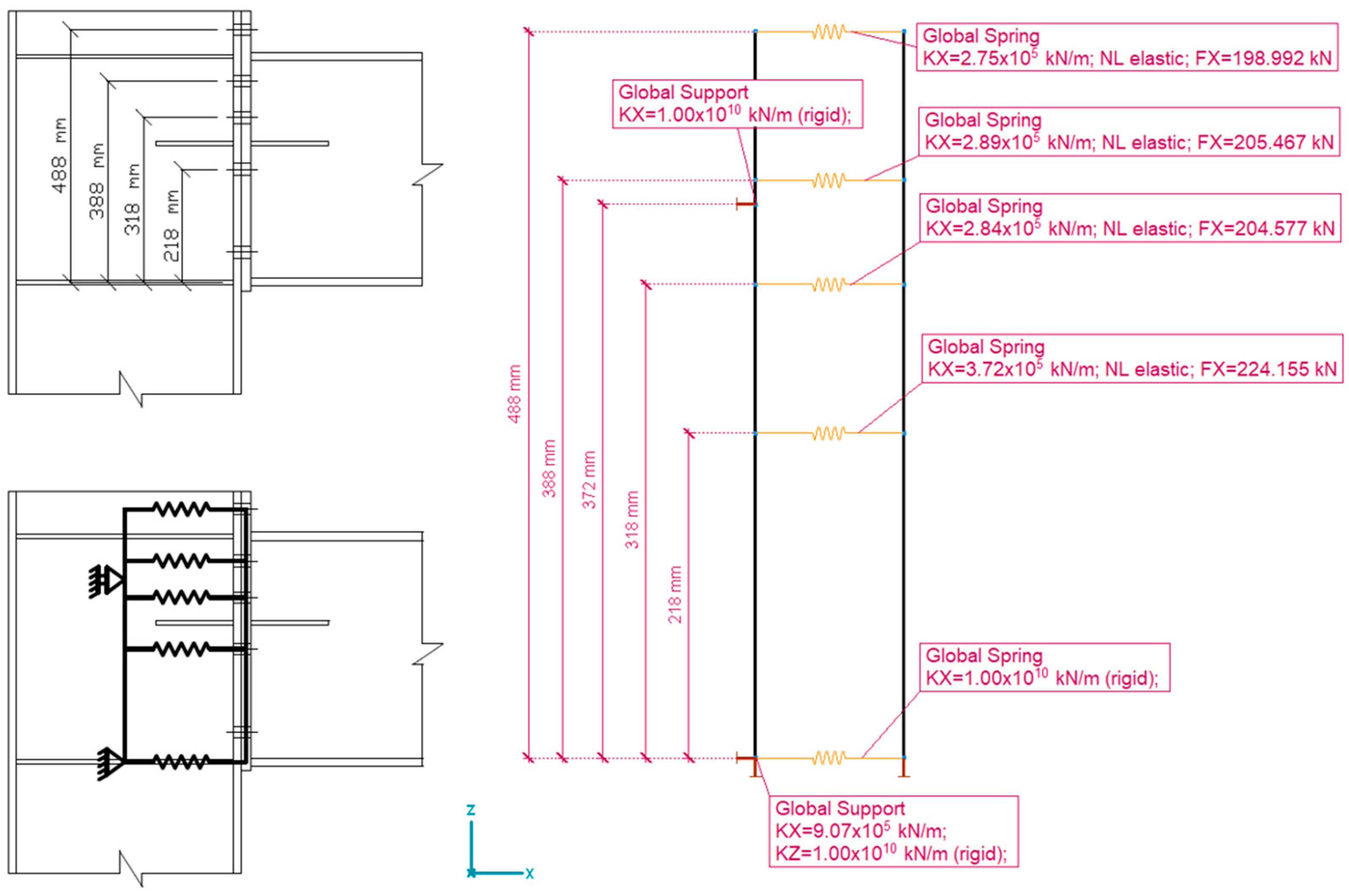
The place of the compression point, which can be defined as a rotation point, is placed in the middle point of the compressed flange of the beam, according to [1]. This assumption will be used; however, there are different opinions presented, for example, in [6]. The distances of the bolt rows from the rotation point are 488 mm for the first bolt row, 388 mm for the second, 318 mm for the third, and 218 mm for the fourth bolt row. The moment calculated with use of the known forces and distances is the moment resistance of the connection. In this case, it is 222.75 kNm.

2.2. Checking the Results with the Mechanical Model

Mechanical spring models combined with the component method are widely used for more accurate and complex check of connections in steel structures, as is the case in [5,6,7,8,9,10,11]. The latest version of the EN 1993-1-8 Standard [1] also contains this possibility. To build up this model, besides the resistance of each component already calculated for the manual method, the stiffness values are also necessary. The calculated values can be seen in Table 2. Multiplying the modulus of elasticity with the stiffness coefficient calculated according to the Standard [1] results in the presented stiffness values. A bi-linear force-elongation function is used. This is in accordance with the principles of the component method defined in [1]. However, in the mechanical model, there is the possibility of taking a reduced post-critical stiffness into account, as presented in [7,8]. The 1.00 × 10¹⁰ values are for infinite stiffness in this calculation.
The two-dimensional spring model of the beam-to-column joint can be seen in Figure 2. It was created and calculated with the use of Axis VM (Version: X7 Release: 3g-qf1, commercial version) finite element software. The model contains two “rigid bodies”. The left one is on the side of the column; the right one is on the side of the beam. With the X directional stiffness of the bottom support of the left rigid body, the stiffness of the “column web in shear” and the “column web in compression” components are considered. The stiffness of the support in the Z direction is infinite. The upper support is a horizontal support with infinite stiffness. The placement of it is defined based on the “equivalent arm of forces”, defined in [1], which is calculated based on the stiffness of each bolt row. It must be mentioned that this value is only valid while all the components are in an elastic state; however, it will not cause significant mistakes in the plastic state neither. The rigid body on the right side is supported by a vertical support with infinite stiffness and with the springs. The spring at the bottom might be replaced with a rigid rod, but it is easier to keep the spring element. The other four springs represent the bolt rows. Each of them stands for the summarized stiffness of five relevant components. In the case of these springs, the definition of non-linear parameters was also necessary. In addition to the stiffness value, it was necessary to also define the load bearing capacity. On the right rigid body, the moment resistance, calculated with the manual calculation, is defined as a load.

2.3. Comparison of the Results

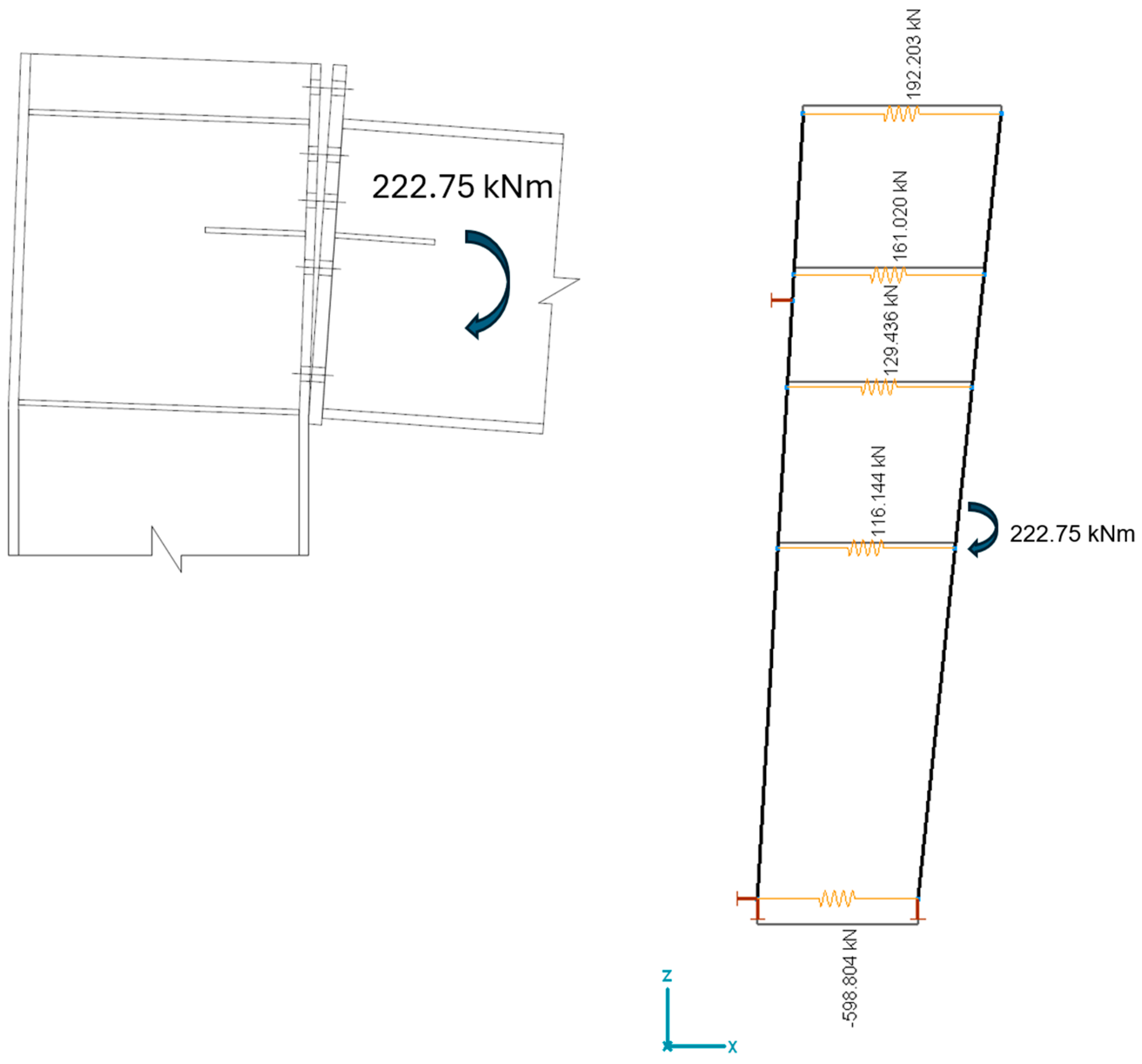
The results of the non-linear calculation can be seen in Figure 3. Comparing these results with the ones given in Table 1, it can be established that the force distribution is different from the results of the manual calculation. The differences are listed below.
  • There are lower forces in the first and second bolt rows (far from the rotation point) in the case of the mechanical model;
  • There are higher forces in the third and fourth bolt rows (closer to the rotation point) in the case of the mechanical model;
  • The force is higher in the compression zone in the case of the mechanical model. This exceeds the calculated limit value for the component “column web in shear”, which means that, according to this model, the moment resistance of the joint is lower than it was calculated with the common assumptions of the manual calculation.
This means that following the provisions of the referenced point of the Standard [1] leads to higher moment resistance compared to the application of a more precise method.
The differences are caused by the simplifications given in chapter number B.3.2.2 of EN 1993-1-8 [1], which are discussed above. Both the handling of the group failure and the handling of a weak component on the compression side (including the shear component) cause that the resultant of the tension forces occurring in the bolt rows will be located farther from the rotation point (409.05 mm), than in the case of the mechanical model of the joint (371.99 mm).
It should be mentioned that none of them are necessarily equal to the “equivalent arm of forces” value (371.99 mm in this example), which is a decisive value in the stiffness calculation of the joint. The reason for the discrepancy has already been discussed in the case of manual calculation. The mechanical model can provide an even lower distance between the resultant forces if any of the bolt rows are in a plastic state. In that case, checking the model with a lower moment, where all the bolt rows are in an elastic state, provides the “equivalent arm of forces” value.

3. The Methodology of the Modified Calculation

To obtain a better match in the results, modifications should be made to the manual application of the component method. Steps of a calculation will be presented, which will provide the same results as the mechanical model without building it in a finite element program. The actual calculations were performed by using the Smath Studio Enterprise Desktop mathematical program (Ver 1.2 (build: 9018) commercial version). This can be found in the “Supplementary Materials” section.

3.1. Defining the Effective Length for Each Bolt Row

The first step of the calculation is to define the effective length values based on the geometry of the connection. The effective length values should be defined for single bolt rows and for all the possible group failure modes. The comparison of the results determines whether individual or group failure is expected. If the effective length calculated for the group is lower compared to the sum of the effective length of the bolt rows involved in the group, then the group failure is relevant.
In this case, their part from the group effective length is considered in each bolt row participating in the group, as is allowed by the first point of chapter 8.3.6 in EN 1993-1-8 [1].
In the later calculation, there will be just one Leff1 and one related Leff2 value used for each bolt row on each side of the connection.

3.2. Defining the Stiffness and Resistance Parameters of the Components

The same components are used as in the original calculation. The resistance and the stiffness of the components are calculated in the same step, according to the prescriptions of the latest version of the EN 1993-1-8 standard [1]. This differs from usual practice, where the moment resistance of the joint is defined first and the calculation of the rotation stiffness of the joint comes afterward, as was suggested by the previous version of the Standard [12]. The partially modified version of this [12], supplemented by the National Application Document, is still valid in Hungary in parallel with the new version [1].
In the modified method, presented here, as in the Mechanical Model Method, the stiffness parameters are necessary to define the moment resistance.
At the end of this step, the bi-linear normal force to elongation diagrams are provided for all the relevant components (in some cases, with infinite initial stiffness).

3.3. The Redistribution of the Forces in the Bolts

As mentioned above, two simplifications of the Standard result in a larger arm of force compared to the mechanical model. The one related to the group of bolts can be eliminated by defining the resistances based on the effective length values described above. The distribution of the forces in the group is based on the effective lengths determined by taking into account the group failure but considering isolated bolt rows.
The effect of the other simplification, which is used, if one of the components “column web in shear”, “column web in compression” or the “beam flange in compression” are weaker compared to the summarized resistance of the tension side, can be handled, with the use of a “while” cycle in a program. According to the results of the spring model, shown in Figure 3, the rigid bodies will have different rotation angles. The total amount of the rotation of the connection caused by the moment appears on the rigid body on the right side (beam side). Only a portion of it appears on the rigid body on the left side (column side). The four springs representing the bolt rows are under tension, so on that side, there will be an elongation in the spring elements, while on the bottom side, the compression will cause shortening in the spring. The different elongation of the connecting springs results in a different rotation of the connected elements. The elongation of the given spring can also be calculated based on the angle between the two rigid bodies and the vertical distance between the bottom point and the examined bolt row. The actual force in a bolt row can be calculated based on Equation (1):
F T _ i _ m o d = min k e f f _ i E h i t a n ( α ) F T R d _ i
where:
keff_i: combined stiffness coefficient of the bolt row number “i”;
E: modulus of elasticity;
hi: distance between the rotation point and the bolt row number “i”;
α: angle between the two rigid bodies;
FTRd_i: combined tension resistance of the bolt row number “i”.
In Equation (1), the first condition handles the elastic state of the bolt row, and the second one represents the plastic state.
The rotation of the rigid bodies causes vertical displacement in both endpoints of the checked spring elements. These displacements are not equal, so the spring elements are not exactly horizontal. This phenomenon can be neglected in practical cases, as the rotation of the rigid bodies are rather small. In the example, 1.613 × 10⁻³ Rad is for the left one, and 2.917 × 10⁻³ Rad is for the right one.
In a “while” cycle, the angle between the rigid bodies is increased in small steps until the sum of the forces determined based on the elongation, stiffness, and limit force of the springs in each row of bolts does not reach the lowest of the total tensile resistance, compression resistance, or shear resistance. This condition is given in Equation (2):
F T b o l t _ m o d min F T R d F c w c R d F c f b R d V w p R d  
where:
FTbolt_mod: the summarized value of the actual tension forces in the bolt rows;
FTRd: the summarized value of the tension resistance of the bolt rows;
FcwcRd: the design resistance of the “column web in compression” component;
FcfbRd: the design resistance of the “beam flange in compression” component;
VwpRd: the design resistance of the “column web in shear” component.

3.4. Compring the Results of the Modified Component Method and the Mechanical Model

The partial results of the calculation can be seen in Table 3. Compared to Table 1, the only difference in the resistance values is that in this case, the group failure resistance of the bolt row numbers 2 and 3 is divided between the concerned bolt rows. It can be seen that, also in this case, the group failure is relevant. The sum of the two resistances is equal to the value of the group resistance in Table 1. In this specific case, the resistance values of the two bolt rows are nearly equal because the positions of these two bolt rows are quite similar. In both cases, there is something—the upper flange of the beam and the stiffener in the column by the bolt row number 2, and the stiffeners on both sides in the case of bolt row number 3—that provides extra strength and stiffness.
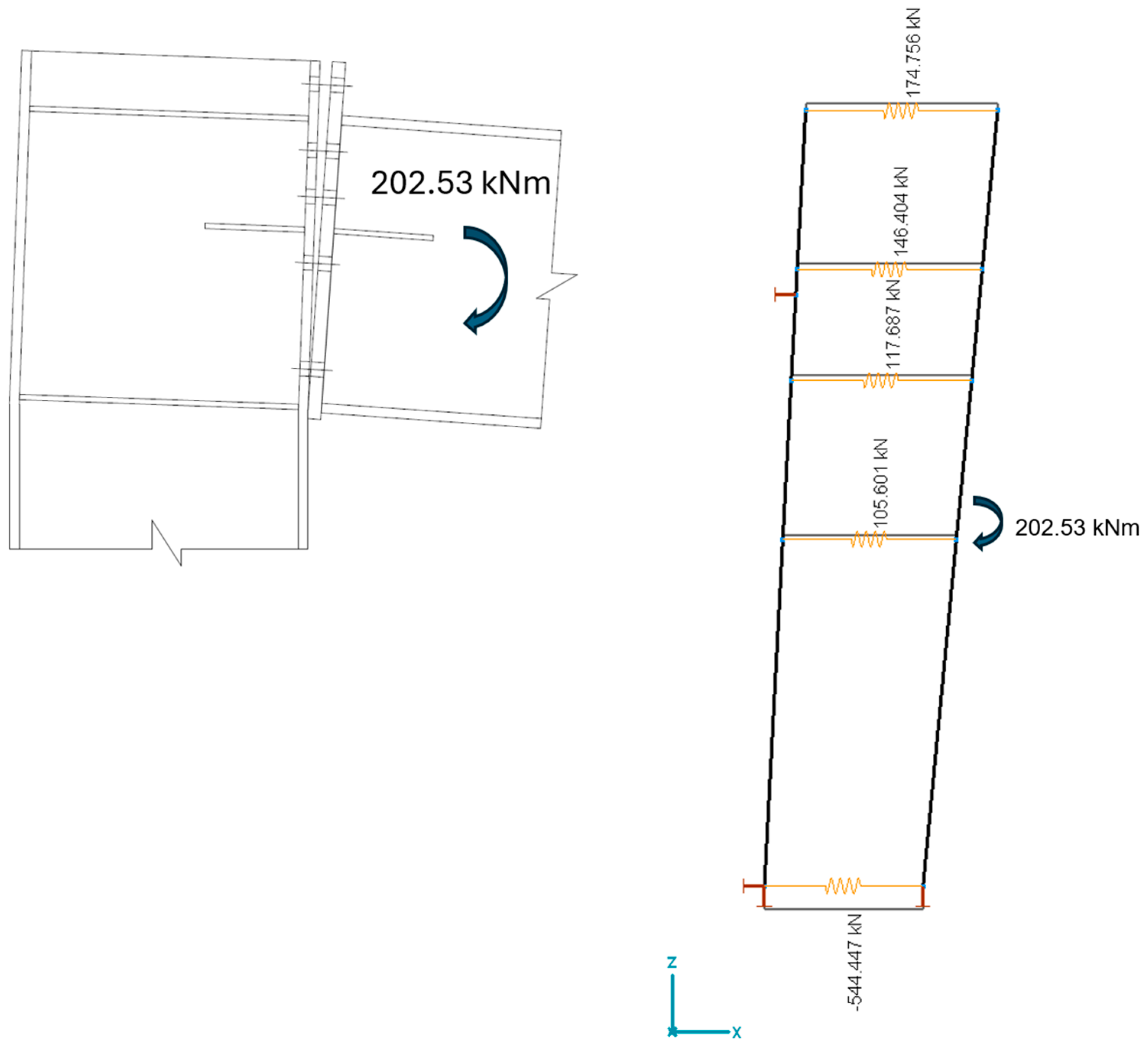
There is no change in the approximated forces on the compression side. The differences compared to the original method can be found by the approximated forces in the bolt rows. Based on these results, the moment resistance is 202.53 kNm. This is 90.92% of the result of the original manual calculation.
The check of the force distribution with the use of the mechanical model (same as before) can be seen in Figure 4. The maximal difference can be found in bolt row number 1. This is 0.01 kN.
The difference between the total value of the tension side and the total value of the compression side indicates a small inaccuracy of the calculation. It is 0.103 kN in this case. On one hand, it can be caused by rounding; on the other hand, the chosen angle steps in the calculation cannot provide the exact angle between the two rigid bodies. The latter can be corrected by choosing lower angle steps, but that means longer calculation time.

4. Discussion

Although the manual calculation and the mechanical model presented in the EN 1993-1-8 Standard [1] should lead to the same result, there are cases where differences can be found. In the case of the presented example, the manual calculation results in higher moment resistance compared to the more reliable mechanical model, at the expense of safety. This is caused by two approximations presented in the EN 1993-1-8 Standard [1]. Proceeding the reduction in bolt force due to the group failure and/or due to the “weak” shear component or compression components, just in the bolt rows closer to the compression zone is a significant simplification in the calculation, but can be dangerous, because the resultant of the forces in the bolts predicted to be further from the compression zone, than in the reality. The longer arm of the pair of force leads to higher moment resistance compared to the mechanical model. The force distribution in the mechanical model is obviously more realistic.
The difference in the calculated moment resistances based on the two original methods is influenced by several effects interacting with each other. The most significant is a large difference in the absolute values of the summarized tension resistance and the lowest among the compression resistances or the shear resistance, assuming that the tensile resistance is greater. There are methods to increase the resistance of the “weak” compression components or the shear component. This can solve the problem, but may lead to a less economical solution. The difference between the summarized individual resistance of the bolt rows in the group and the group failure resistance is the other effect. Group failure usually cannot be avoided. Limiting the number of bolt rows used in a group to two helps reduce the mistake, but will not eliminate it. And both previously mentioned effects are also influenced by the bolt pattern of the connection. The detection and treatment of these problems can be completed by examining the partial results of the calculation and modifying the connection several times. However, it is recommended in such cases, when the original manual calculation applies any approximations at the expense of safety, to use the mechanical model or the modified calculation presented here instead to define the force distribution.
Compared to make a mechanical model in a finite element software, it is much easier to use the modified calculation method. It does not require more work than the original manual calculation. It uses the same input data. With the exception of one, the same calculation steps are required, only in a modified sequence. The main difference is in the determination of the forces occurring in the bolt rows. The presented method determines it based on the operating principle of the mechanical model. Thus, apart from the rounding errors and errors due to the size of the step in the angle, it produces the same results with the most accurate method, the mechanical model method.
Since the method closely approximates the results of an already validated method, it can also be considered validated. Regardless, further checks of the method are under development in complex finite element models and full-scale experiments. The loading device presented in [13,14] could be suitable for this purpose. But in this case, it will not be enough to see that the connection fails at a given load due to the low shear resistance of the column; the value of the tensile forces occurring in the screws also must be measured.
In the presented form, the modified manual calculation method is not suitable for real manual calculation because of the “while” cycle in it, but it can be performed with different mathematical software which are already used in structural design practice. As a further simplification, the “while” cycle may be replaced with a “controlled trial of the rotation angles” that can quickly lead to good results, for example, in the Excel program. The real manual calculation is extremely rare when using the component method because of the complexity of the calculation. The most common way of checking the joints in structural design practice is the use of the special modules of finite element software. These modules can be made even simpler and easier to use by incorporating the method presented in this paper.

5. Conclusions

With the use of the modified manual calculation method presented here, the simplifications in the definition of the force distribution, which results in higher moment resistance at the expense of safety, can be eliminated. This modified manual calculation is on the same difficulty level as the original calculation, but is much more accurate. It always provides results that closely match the results of the mechanical model, which can be considered as a benchmark.

Supplementary Materials

The following supporting information can be downloaded at https://www.mdpi.com/article/10.3390/buildings14113553/s1: Full check of the joint with the Modified Component Method: MCMcalc.pdf.

Author Contributions

Investigation, L.R.; methodology, L.R.; software, L.R.; supervision, I.K.; validation, L.R.; visualization, L.R. and I.K.; writing—original draft, L.R.; writing—review and editing, I.K. All authors have read and agreed to the published version of the manuscript.

Funding

The APC was funded by the University of Debrecen.

Data Availability Statement

Data are contained within the article.

Acknowledgments

Supported by the University of Debrecen Program for Scientific Publication. The commercial version of the Axis VM, the SMath and the CMS IntelliCad programs were provided by the StatiCalc Ltd. for the research project.

Conflicts of Interest

The authors declare no conflicts of interest.

Abbreviations

The following are the notations used in the article in alphabetical order.
αAngle between the two rigid bodies in Figure 3
EModulus of elasticity
FcfbRdThe design resistance of the “beam flange in compression” component
FcwcRdThe design resistance of the “column web in compression” component
FTbolt_mod∑The summarized value of the actual tension forces in the bolt rows
FTRd_iCombined tension resistance of the bolt row number “i”
FTRd∑The summarized value of the tension resistance of the bolt rows
hiDistance between the rotation point and the bolt row number “i”
keff_iCombined stiffness coefficient of the bolt row number “i”
VwpRdThe design resistance of the “column web in shear” component

References

  1. EN 1993-1-8; Eurocode 3: Design of Steel Structures, Part 1-8: Design of Joints. European Committee for Standardization: Brussels, Belgium, 2024.
  2. InterCad Ltd. Axis VM 17, Commercial version; SC1 steel connection design module; InterCad Ltd.: Budapest, Hungary, 2023. [Google Scholar]
  3. StruSoft Ltd. FEM-Design, Educational version; Steel connection design module; StruSoft Ltd.: Malmö, Sweden, 2023. [Google Scholar]
  4. ConSteel Solutions Ltd. ConSteel Joint, Educational version; ConSteel Solutions Ltd.: Budapest, Hungary, 2023. [Google Scholar]
  5. Golea, T.; Corman, A.; Mathieu, J.; Duchêne, Y.; Jaspart, J.P.; Demonceau, J.F. An innovative mechanical model for structural steel joints. Eng. Struct. 2023, 277, 115459 . [Google Scholar] [CrossRef]
  6. Gil-Martín, L.M.; Hernández-Montes, E. A compact and simpler formulation of the component method for steel connections. J. Constr. Steel Res. 2020, 164, 105782. [Google Scholar] [CrossRef]
  7. Da Silva, L.S.; Coelho, A.G. Ductility model for steel connections. J. Constr. Steel Res. 2001, 57, 45–70. [Google Scholar] [CrossRef]
  8. Coelho, A.G.; da Silva, L.S.; Bijlaard, F.S. Ductility analysis of bolted extended end plate beam-to-column connections in the framework of the component method. Steel Compos. Struct. 2006, 6, 33–53. [Google Scholar] [CrossRef]
  9. Golea, T.; Bodson, R.; De Ville De Goyet, V.; Jaspart, J.P.; Demonceau, J.F. A generalised mechanical model for the characterisation of steel joints. Ce/Paper 2023, 6, 1222–1227. [Google Scholar] [CrossRef]
  10. Bayo, E.; Cabrero, J.M.; Gil, B. An effective component-based method to model semi-rigid connections for the global analysis of steel and composite structures. Eng. Struct. 2006, 28, 97–108. [Google Scholar] [CrossRef]
  11. Rasmussen, K.J.R.; Zhao, X.; Yan, S.; Dai, L.; Zhu, C.; Jiang, L. Recent developments of the Component Method. Ce/Paper 2019, 3, 313–323. [Google Scholar] [CrossRef]
  12. EN 1993-1-8; Eurocode 3: Design of Steel Structures, Part 1-8: Design of Joints. European Committee for Standardization: Brussels, Belgium, 2010.
  13. Son, M.P. Experimental determination of yield in beam-to-column flange connections. IOP Conf. Ser. Mater. Sci. Eng. 2019, 687, 033006. [Google Scholar] [CrossRef]
  14. Da Silva, L.S.; Simoes, R.D.; Cruz, P.J. Experimental behaviour of end-plate beam-to-column composite joints under monotonical loading. Eng. Struct. 2001, 23, 1383–1409. [Google Scholar] [CrossRef]
Figure 1. The geometry of the examined connection.
Buildings 14 03553 g001
Figure 2. Mechanical model with stiffness and load bearing settings.
Buildings 14 03553 g002
Figure 3. Force distribution in the joint calculated with the mechanical model to check the results of the manual calculation. (Normal forces in the springs are presented).
Buildings 14 03553 g003
Figure 4. Force distribution in the joint calculated with the mechanical model to check the results of the modified application of the component method (normal forces presented).
Buildings 14 03553 g004
Table 1. Partial results of the moment resistance calculation with the manual version of the component method.
ResistanceApproximated Force in
Component
Single2–3 as a Group
[kN][kN][kN]
Tension sideBolt row no. 1198.992198.992198.992
Bolt row no. 2225.045410.044225.045
Bolt row no. 3224.155120.505
Bolt row no. 4224.155224.1550.000
Total (Sum)872.347833.191544.542
Compression sideColumn web in compression733.977544.542
Beam flange in compression918.513544.542
Column web in shear544.542544.542
Total (min)544.542544.542
Table 2. Stiffness values of each component in the example connection.
Stiffness of the Replacing Spring Element [kN/m]
Column Web in
Tension
Column Flange in BendingBolt in TensionEndplate in BendingBeam Web in TensionTotal
Bolt row no. 14.40 × 1053.06 × 1061.46 × 1062.82 × 1061.00 × 10102.75 × 105
Bolt row no. 24.55 × 1053.17 × 1061.46 × 1063.92 × 1061.00 × 10102.89 × 105
Bolt row no. 34.46 × 1053.11 × 1061.46 × 1063.63 × 1061.00 × 10102.84 × 105
Bolt row no. 46.29 × 1054.38 × 1061.46 × 1065.29 × 1061.00 × 10103.72 × 105
C. web in comp.1.00 × 1010
B. flange in comp.1.00 × 1010
C. web in shear9.07 × 105
Table 3. Partial results of the moment resistance calculation with the modified application of the component method.
ResistanceApproximated Force in
Component
Single2–3 as a Group
[kN][kN][kN]
Tension sideBolt row no. 1198.992198.992174.746
Bolt row no. 2225.045205.467146.399
Bolt row no. 3224.155204.577117.686
Bolt row no. 4224.155224.155105.608
Total (Sum)872.347833.191544.439
Compression sideColumn web in compression733.977544.439
Beam flange in compression918.513544.439
Column web in shear544.542544.439
Total (min)544.542544.439
Disclaimer/Publisher’s Note: The statements, opinions and data contained in all publications are solely those of the individual author(s) and contributor(s) and not of MDPI and/or the editor(s). MDPI and/or the editor(s) disclaim responsibility for any injury to people or property resulting from any ideas, methods, instructions or products referred to in the content.