
Study on Error Influence Analysis of an Annular Cable Bearing-Grid Structure


Abstract
1. Introduction
2. Random Error Influence Analysis Method
2.1. Basic Theory
- (1)
- The sign and magnitude of the error are both uncertain quantities.
- (2)
- As the number of samples increases, the average value of the error will gradually tend to 0.
- (3)
- If the number of samples is large enough, the distribution of random errors will also show a certain regularity [8].
2.2. Error Distribution Model
- (1)
- Utilize the normal distribution theory to define the error distribution model of ∆L1, ∆L2 and ∆C.
- (2)
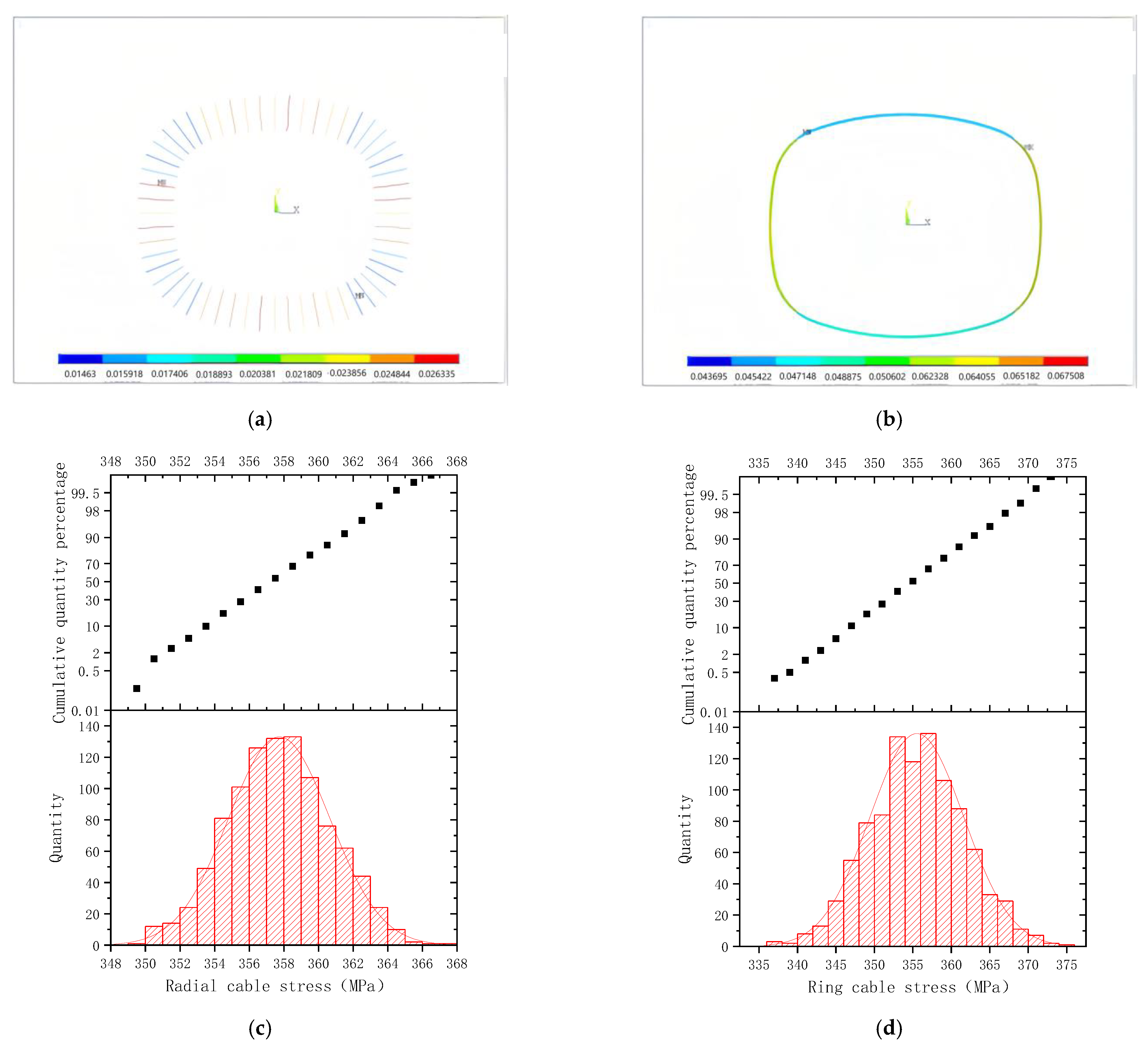
- Generate 1000 error samples in random, while each error sample is a calculation error condition of the structure of the Qatar Education City Stadium. Likewise, these 1000 error samples also conform to the normal distribution. Among them, the statistical error distribution of a radial cable, a ring cable, and a ring beam are shown in Figure 2.
- (3)
- Each generated error case will be introduced into the simulation model and form the calculation case of the defective structure.
- (4)
- Perform the numerical calculate of each defect condition and obtain the error effect of the simulation model under each condition.
- (5)
- Compare the cable stress under the non-defect condition and the defect conditions, and obtain the maximum stress error.
- (6)
- Determine whether the maximum stress error meets the requirements. If it does meet the requirements, the allowable range of the error parameters is set reasonably. Otherwise, adjust the allowable range of the error parameters, and perform steps (1)~(5) again until a reasonable allowable range of the error parameters is obtained.
3. Analysis and Results
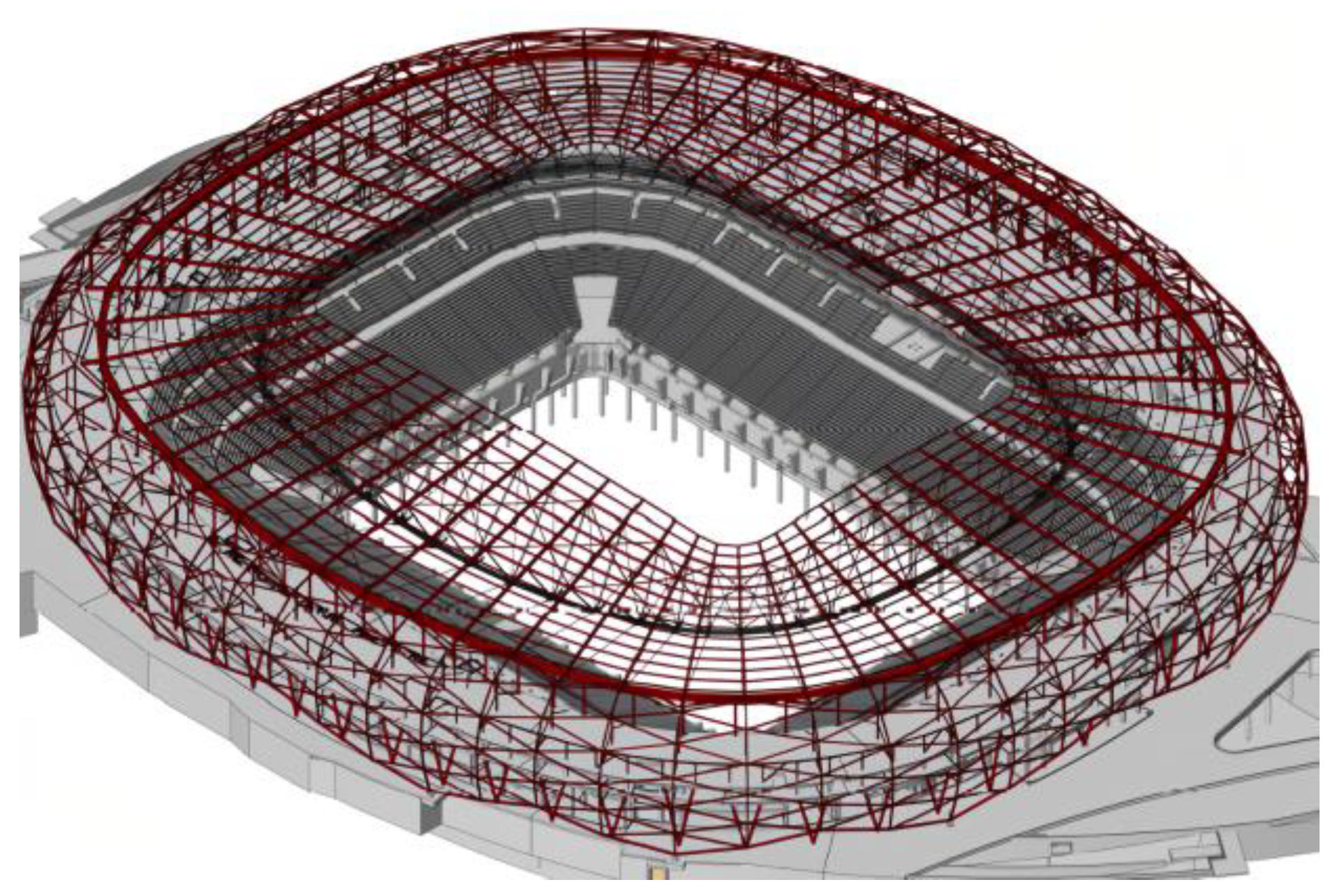
3.1. Project Overview
3.2. Analysis Model
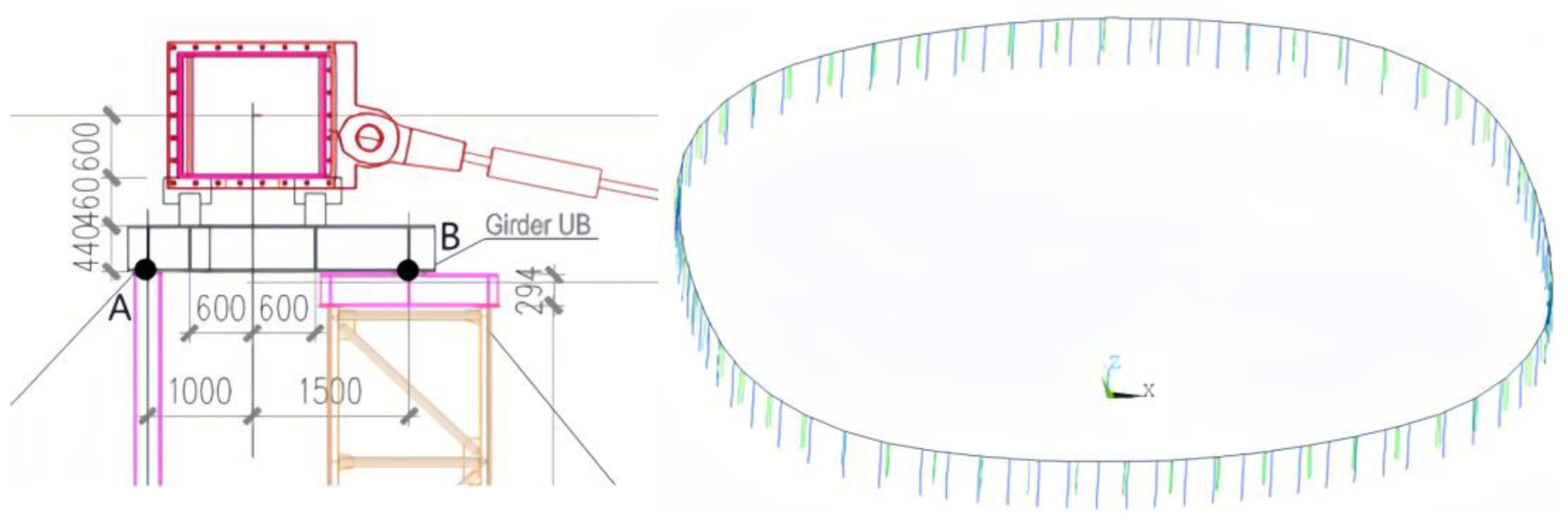
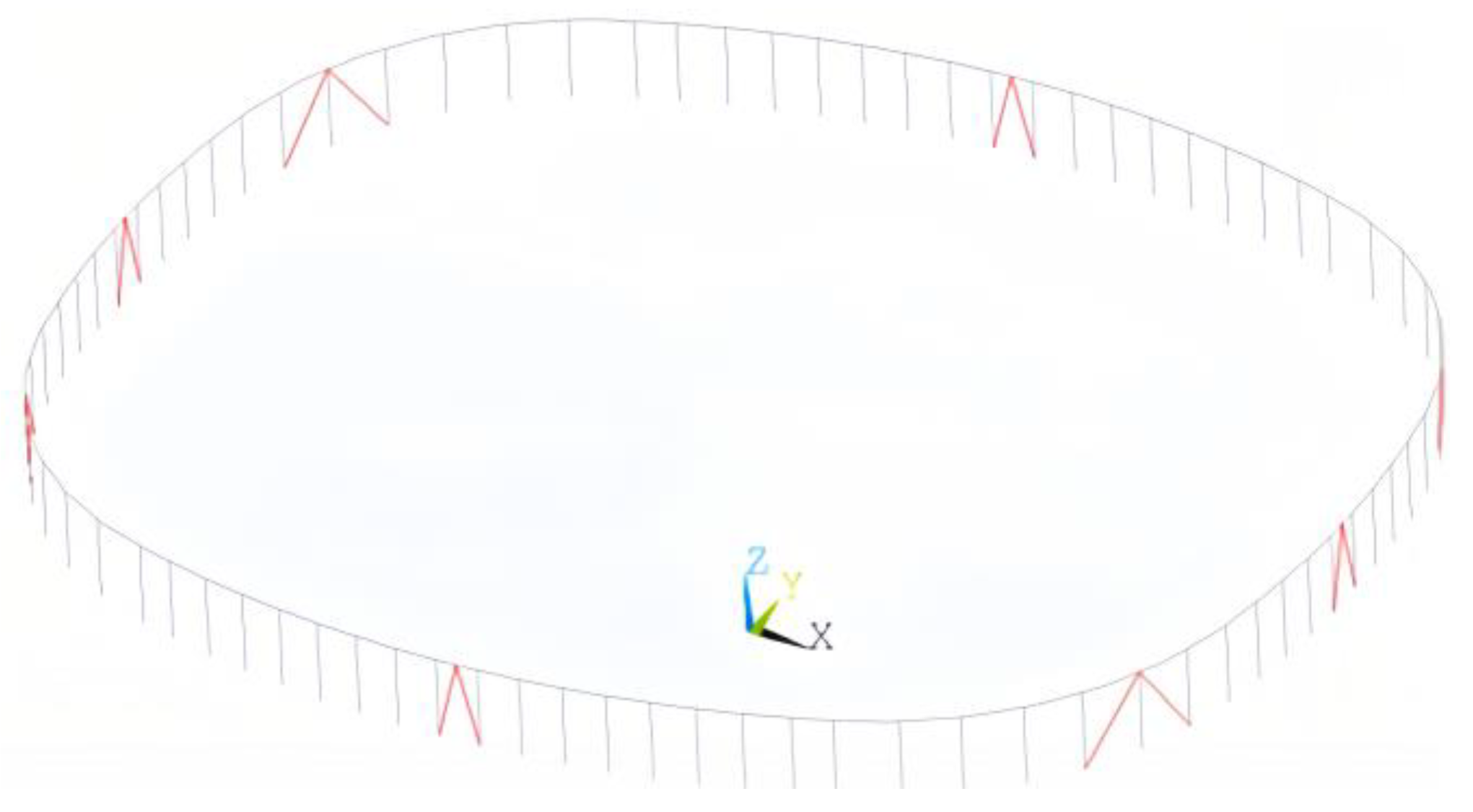
- (1)
- Ring beam support frame
- (2)
- Cross braces between columns
3.3. Overview of Analysis Objects
3.4. Load Conditions
- (1)
- Dead load (the self-weight of the structure, considering the magnification factor of 0.15 times)
- (2)
- Prestressing (including radial cables, ring cables, and external compression ring beams)
- (3)
- Random errors in the length of the cables and the external pressure ring beam
3.5. Error Combination
4. Influence Analysis of Independent Error Effect
4.1. Radial Cable Length Error
4.2. Ring Cable Length Error
4.3. Ring Beam Length Error
4.4. Analysis Summary
5. Coupling Error Effect Analysis
5.1. Combination 4#
5.2. Combination 5#
5.3. Combination 6#
5.4. Combination 7#
5.5. Combination 8#
5.6. Analysis Summary
- (1)
- With the increase in the maximum allowable value of the length error of the outer pressure ring beam, the error ratio of the radial cable, the error ratio of the ring cable, and the stress error of the outer pressure ring beam also increase. The maximum radial cable force error ratio of Combination 8# is 8.61%, and the maximum cable force error ratio of the ring cable is 10.13%, which has reached the maximum allowable error ratio of 10% in specification. The maximum value of the equivalent stress error of the external pressure ring beam is 13.5 MPa.
- (2)
- From the calculation and analysis of error combinations 4# to 8#, it can be seen that the maximum cable force error ratio of the ring cable is greater than that of the radial cable, which shows that the sensitivity of the ring cable force to the error is higher than that of the radial cable force.
6. Discussion
6.1. Discussion of Error Effect Analysis
6.2. Limitations
6.3. Advantages and Innovations of the Methods
7. Conclusions
- (1)
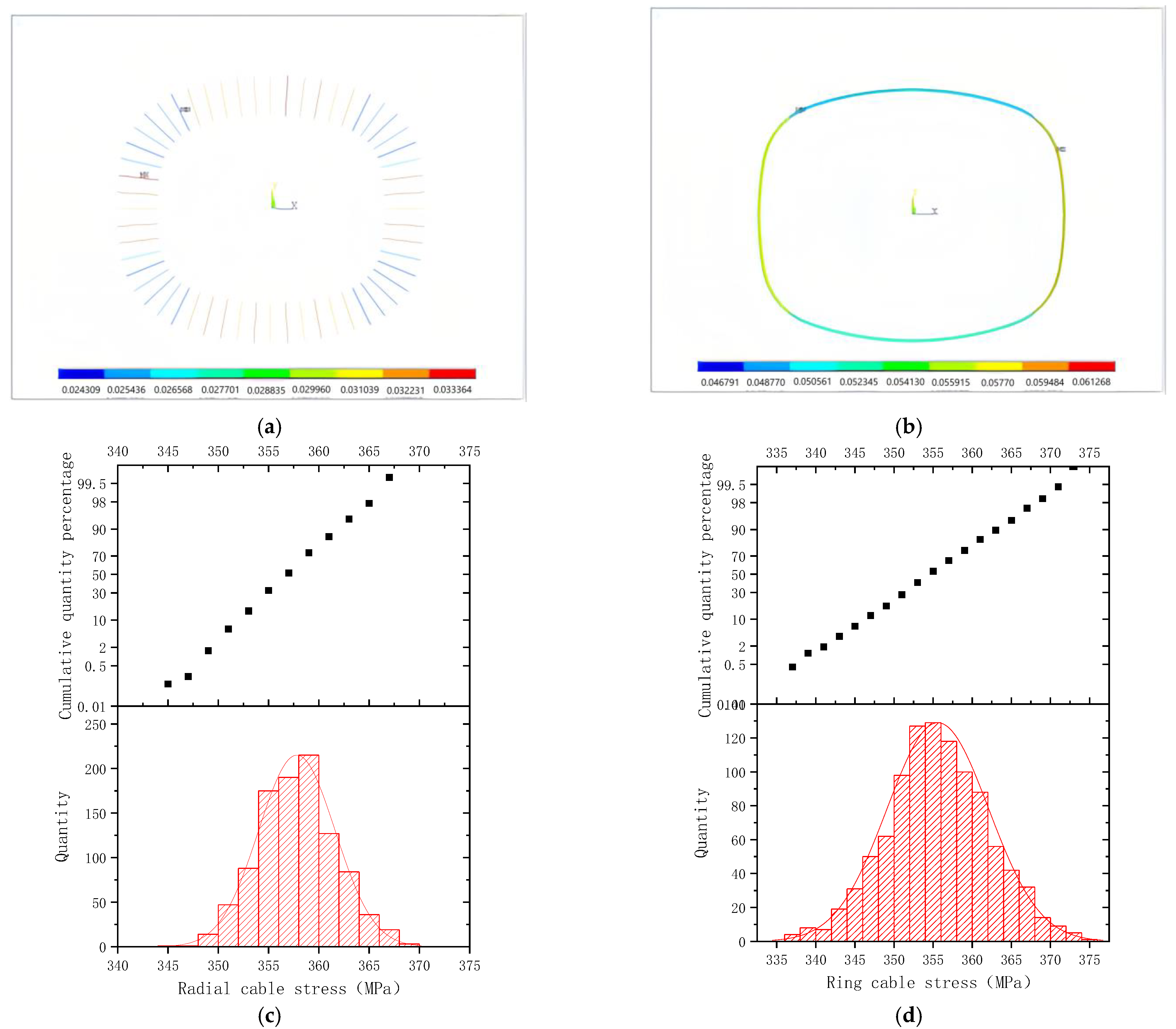
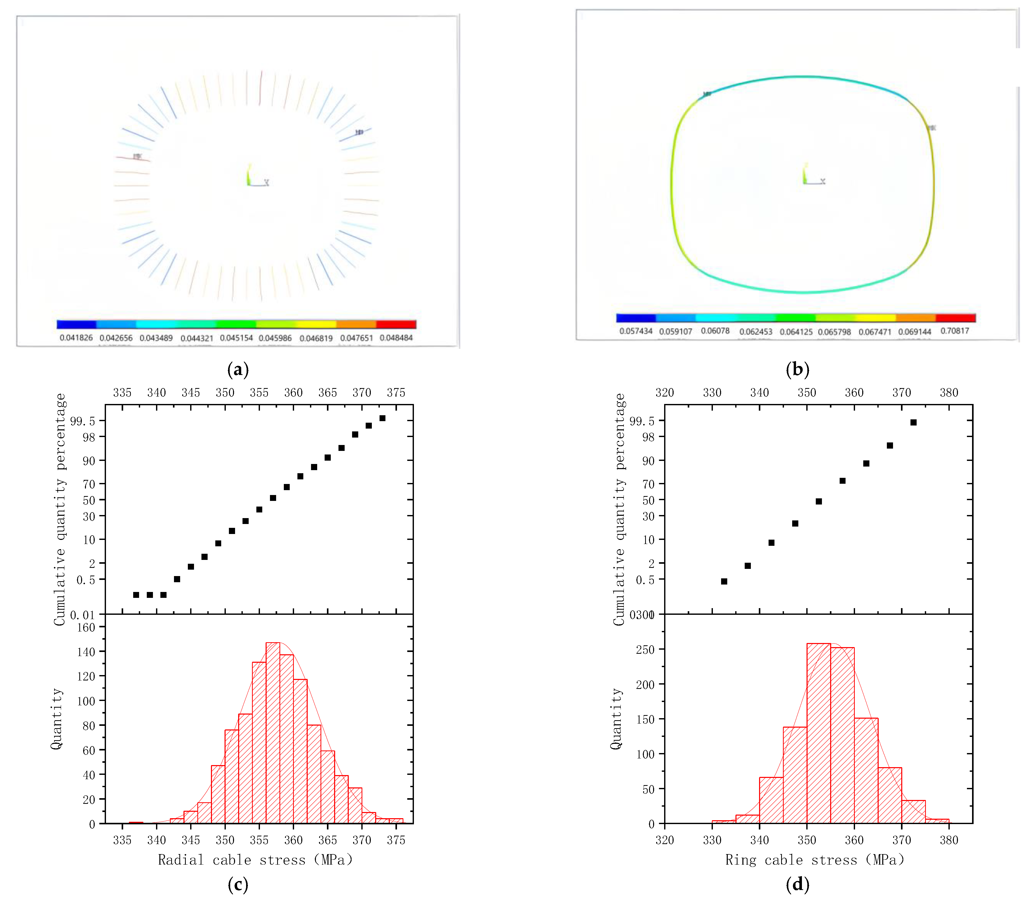
- The input 1000 random error samples all conform to normal distribution, and the error responses of the structure also conform to the normal distribution.
- (2)
- In the independent error analysis, if the maximum allowable error of the length of the outer compression ring beam is set as ±170 mm, structural response generated by the independent error of the outer compression ring beam is the most obvious, the absolute values of the cable force error ratios of the radial cable and the ring cable are both close to 8.3%, and the maximum value of the equivalent stress error of the external pressure ring beam is 13.5 MPa.
- (3)
- When considering the coupling effects of the radial cable, ring cable length error, and external pressure ring beam length error, the resulting cable force error and ring beam stress error are not a linear superposition of the structural response under the independent action of various errors, but a certain discounts occur. Meanwhile, from combinations 4# to 8#, with the increasing length error of the external pressure ring beam, the error response of the structure is becoming increasingly apparent. When the maximum allowable length error of the outer pressure ring beam is set as ±170 mm, the cable force error ratios of the structure reach the maximum allowable error ratio of 10% mentioned in the specification, under the coupling action of the cable force errors of the radial cable and the ring cable.
- (4)
- It is feasible to use fixed-length cables in the Qatar Education City Stadium project. The control standard for |efr| ≤ 10% can be set as ∆1L ≤ ±0.03%L0 for radial cable length error, for ring cable length error, and ∆C ≤ ±170 mm for the length error of the outer pressure ring beam.
- (5)
- As a natural extension of this study, the error impact analysis method proposed in this study will be used to analyze other types of cable trough structures, such as cable dome, Soteras, cable net, cantilever structure, etc.
Author Contributions
Funding
Institutional Review Board Statement
Informed Consent Statement
Data Availability Statement
Conflicts of Interest
References
- Wan, Z.; Cao, Z.; Sun, Y.; Fan, F. Experimental and numerical research on the structural behaviour of a Tensairity dome. Eng. Struct. 2021, 248, 113225. [Google Scholar] [CrossRef]
- Liu, F.; Wang, L.; Jin, D.; Wen, H. Equivalent continuum modeling of beam-like truss structures with flexible joints. Acta Mech. Sin. 2019, 35, 1067–1078. [Google Scholar] [CrossRef]
- Zhang, Y.; Wei, Y.; Bing, L.; Wang, G.; Huang, L. A novel seawater and sea sand concrete-filled FRP-carbon steel composite tube column: Seismic behavior and Finite-Element Analysis. Eng. Struct. 2022, 270, 114872. [Google Scholar] [CrossRef]
- Dong, F.H.; Zhang, H.H. Probabilistic Safety Factor Calculation of the Lateral Overturning Stability of a Single-Column Pier Curved Bridge under Asymmetric Eccentric Load. Symmetry 2022, 14, 1534. [Google Scholar] [CrossRef]
- Wei, Y.; Zhu, C.; Miao, K.; Chai, J.; Zheng, K. Compressive behavior of rectangular concrete-filled fiber-reinforced polymer and steel composite tube columns with stress-release grooves. Compos. Struct. 2022, 281, 114984. [Google Scholar] [CrossRef]
- Chen, S.; Wei, Y.; Ding, M.; Zhao, K.; Zheng, K. Combinatorial design and flexural behavior of laminated bamboo-timber composite beams. Thin Wall Struct. 2022, 181, 109993. [Google Scholar] [CrossRef]
- Bäck, J.; Nobile, F.; Tamellini, L.; Tempone, R. Stochastic spectral Galerkin and collocation methods for PDEs with random coefficients: A numerical comparison. In Spectral and High Order Methods for Partial Differential Equations; Springer: Berlin/Heidelberg, Germany, 2011; pp. 43–62. [Google Scholar]
- Nobile, F.; Tempone, R.; Webster, C.G. A sparse grid stochastic collocation method for partial differential equations with random input data. SIAM J. Numer. Anal. 2008, 46, 2309–2345. [Google Scholar] [CrossRef]
- Chen, L.M.; Deng, H.; Ye, X.G.; Dong, S.L.; Zhou, Y.Y. Theoretical analysis and experimental research on element-length error sensitivity of cable-bar tensile structures. J. Build. Struct. 2015, 36, 93–100. (In Chinese) [Google Scholar]
- Chen, L.; Hu, D.; Deng, H.; Cui, Y.; Zhou, Y. Optimization of the construction scheme of the cable-strut tensile structure based on error sensitivity analysis. Steel Compos. Struct. 2016, 21, 1031–1043. [Google Scholar] [CrossRef]
- Yang, Y. Optimal topology design of replaceable bar dampers of a reticulated shell based on sensitivity analysis. Earthq. Eng. Eng. Vib. 2014, 1, 113–124. [Google Scholar] [CrossRef]
- Zong, Y.L.; Hu, N.G.; Duan, B.Y.; Yang, G.G.; Cao, H.J.; Xu, W.Y. Manufacturing error sensitivity analysis and optimal design method of cable-network antenna structures. Acta Astronaut. 2016, 120, 182–191. [Google Scholar] [CrossRef]
- Kong, X.; Jiang, P.; Wang, Q.M. A Study of Influences of Value Variations of Structural Parameters on Forces in Cables in the Net Structure of Cables of the FAST. Astron. Res. Technol. 2015, 12, 159–165. [Google Scholar]
- Hu, N.; Zhang, Y.; Yang, G.; Yang, D. Global sensitivity analysis for cable-network antennas by Kriging models with a sensitivity-based accuracy indicator. J. Mech. Sci. Technol. 2023, 37, 4137–4147. [Google Scholar] [CrossRef]
- Sun, Z.; Duan, B.; Zhang, Y.; Yang, D. Influence and experiment of cable-net manufacturing errors on surface accuracy of mesh reflector antennas. Chin. J. Aeronaut. 2023, 36, 363–376. [Google Scholar] [CrossRef]
- Wang, L.; Ding, M.; Ruan, Y.; Luo, B.; Guo, J. Error Influence Simulation of the 500 m Aperture Spherical Radio Telescope Cable-Net Structure Based on Random Combinations. Sustainability 2023, 15, 15061. [Google Scholar] [CrossRef]
- Luo, B.; Sun, Y.; Guo, Z.X.; Pan, H. Multiple random-error effect analysis of cable length and tension of cable–strut tensile structure. Adv. Struct. Eng. 2016, 19, 1289–1301. [Google Scholar] [CrossRef]
- Bonizzoni, F.; Nobile, F. Regularity and sparse approximation of the recursive first moment equations for the lognormal Darcy problem. Comput. Math. Appl. 2020, 80, 2925–2947. [Google Scholar] [CrossRef]
- Bonizzoni, F.; Nobile, F.; Kressner, D. Tensor train approximation of moment equations for elliptic equations with lognormal coefficient. Comput. Method. Appl. Mech. Eng. 2016, 308, 349–376. [Google Scholar] [CrossRef]
- Chen, L.M.; Gao, W.F.; Hu, D.; Zhou, Y.Y.; Zhang, F.B.; Dong, S.L. Determination of a Monitoring Scheme for Controlling Construction Errors of a Cable-strut Tensile Structure. KSCE J. Civ. Eng. 2018, 22, 4030–4037. [Google Scholar] [CrossRef]
- Yang, C.; Xia, Y. Interval Uncertainty-oriented Optimal Control Method for Spacecraft Attitude Control. IEEE Trans. Aerosp. Electron. Syst. 2023, 59, 5460–5471. [Google Scholar] [CrossRef]
- Yang, C.; Lu, W.; Xia, Y. Reliability-constrained optimal attitude-vibration control for rigid-flexible coupling satellite using interval dimension-wise analysis. Reliab. Eng. Syst. Safe 2023, 237, 109382. [Google Scholar] [CrossRef]
- Yang, C.; Xia, Y. A novel two-step strategy of non-probabilistic multi-objective optimization for load-dependent sensor placement with interval uncertainties. Mech. Syst. Signal Process. 2022, 176, 109173. [Google Scholar] [CrossRef]
- Asghari, R.; Abedi, K.; Chenaghlou, M.R. Investigation into pre-stress modes and optimal layout of a new hybrid cable-strut system. Adv. Struct. Eng. 2020, 23, 1259–1275. [Google Scholar] [CrossRef]
- Diaz, J.J.D.C.; Nieto, P.J.G.; Fresno, D.C.; Fernández, E.B. Non-linear analysis of cable networks by FEM and experimental validation. Int. J. Comput. Math. 2009, 86, 301–313. [Google Scholar] [CrossRef]
- Wang, Z.; Yi, T.H.; Yang, D.H.; Li, H.N.; Liu, H. Eliminating the Bridge Modal Variability Induced by Thermal Effects Using Localized Modeling Method. J. Bridge Eng. 2021, 26, 04021073. [Google Scholar] [CrossRef]
- Interpretations for ASCE/SEI 19-10; Structural Applications of Steel Cables for Buildings. American Society of Civil Engineers: Reston, VA, USA, 2014. [CrossRef]
- The Ministry of Housing and Urban Rural Development of China. Technical Standard For Prestressed Steel Structures. JGJ/T 497-2023. Available online: http://www.ccsn.org.cn/Zbbz/Show.aspx?Guid=32e5f6cb-519c-4128-8813-49ea388f4a61 (accessed on 1 January 2020).
- Jin, X.F.; Fan, F.; Shen, S.Z. Parameter sensitivity analysis of the cable-net structure supporting the reflector of a large radio telescope-FAST. Tumu Gongcheng Xuebao/China Civ. Eng. J. 2010, 43, 12–19. (In Chinese) [Google Scholar]
- Duan, M.J.; Suo, X.C.; Dong, F.H.; Li, J.H.; Li, G.F. Research on the Control Method for the Reasonable State of Self-Anchored Symmetry Suspension Bridge Stiffening Girders. Symmetry 2022, 14, 935. [Google Scholar] [CrossRef]
- Li, Q.W.; Jiang, P.; Li, H. Prognostics and health management of FAST cable-net structure based on digital twin technology. Res. Astron. Astrophys. 2020, 20, 49–56. [Google Scholar] [CrossRef]


| Standard | L0 | Error Limitation |
|---|---|---|
| ASCE/SEI STANDARD 19-10 | ≤8.54 m | ±2.54 (mm) |
| >36.59 m |
| Member Name | Section/mm | Elastic Modulus Before Yield/MPa | Yield Strength /MPa |
|---|---|---|---|
| Outer pressure ring beam | 1200 × 40 | 2.06 × 10⁵ | 420 |
| Radial cable | Φ75~Φ135 | 1.60 × 10⁵ | 420 |
| Annular ring cables | 8Φ110 | 1.60 × 10⁵ | 420 |
| Strut | Φ120 × 15 | 2.06 × 10⁵ | 420 |
| Error Combination | Radial Cable Length Error | Ring Cable Length Error | Length Error of External Pressure Ring Beam |
|---|---|---|---|
| 1 | —— | —— | |
| 2 | —— | —— | |
| 3 | —— | —— | |
| 4 | —— | ||
| 5 | |||
| 6 | |||
| 7 | |||
| 8 |
| Extreme Value | Maximum Stress Element | Minimum Stress Element | |
|---|---|---|---|
| Stress of radial cables/MPa | Theoretical value | 378.4 | 338.8 |
| Maximum value | 388.2 | 343.9 | |
| Minimum value | 368.5 | 333.7 | |
| Stress of ring cables/MPa | Theoretical value | 358.1 | 351.3 |
| Maximum value | 359.6 | 352.8 | |
| Minimum value | 356.6 | 349.9 | |
| Stress of external pressure ring beam/MPa | Theoretical value | −158.1 | −82.0 |
| Maximum value | −160.4 | −85.0 | |
| Minimum value | −155.9 | −78.9 | |
| Extreme Value | Maximum Stress Element | Minimum Stress Element | |
|---|---|---|---|
| Stress of radial cables/MPa | Theoretical value | 378.385 | 338.824 |
| Maximum value | 380.505 | 340.727 | |
| Minimum value | 376.275 | 336.931 | |
| Stress of ring cables/MPa | Theoretical value | 358.108 | 351.335 |
| Maximum value | 374.34 | 369.111 | |
| Minimum value | 341.665 | 333.307 | |
| Stress of external pressure ring beam MPa | Theoretical value | −158.088 | −81.997 |
| Maximum value | −159.004 | −82.459 | |
| Minimum value | −157.178 | −81.539 | |
| Extreme Value | Maximum Stress Element | Minimum Stress Element | |
|---|---|---|---|
| Stress of radial cables/MPa | Theoretical value | 378.385 | 338.824 |
| Maximum value | 409.605 | 366.491 | |
| Minimum value | 347.048 | 311.05 | |
| Stress of ring cables/MPa | Theoretical value | 358.108 | 351.335 |
| Maximum value | 386.937 | 380.433 | |
| Minimum value | 329.171 | 322.121 | |
| Stress of external pressure ring beam/MPa | Theoretical value | −158.088 | −81.997 |
| Maximum value | −171.56 | −89.026 | |
| Minimum value | −144.565 | −74.939 | |
| Extreme Value | Maximum Stress Element | Minimum Stress Element | |
|---|---|---|---|
| Stress of radial cables/MPa | Theoretical value | 378.385 | 338.824 |
| Maximum value | 388.36 | 344.15 | |
| Minimum value | 368.292 | 333.436 | |
| Stress of ring cables/MPa | Theoretical value | 358.108 | 351.335 |
| Maximum value | 374.58 | 369.673 | |
| Minimum value | 341.01 | 369.673 | |
| Stress of external pressure ring beam/MPa | Theoretical value | −158.088 | −81.997 |
| Maximum value | −160.575 | −85.024 | |
| Minimum value | −155.705 | −78.893 | |
| Extreme Value | Maximum Stress Element | Minimum Stress Element | |
|---|---|---|---|
| Stress of radial cables/MPa | Theoretical value | 378.385 | 338.824 |
| Maximum value | 390.947 | 347.625 | |
| Minimum value | 365.876 | 330.112 | |
| Stress of ring cables/MPa | Theoretical value | 358.108 | 351.335 |
| Maximum value | 375.972 | 371.056 | |
| Minimum value | 339.775 | 331.504 | |
| Stress of external pressure ring beam/MPa | Theoretical value | −158.088 | −81.997 |
| Maximum value | −162.318 | −85.556 | |
| Minimum value | −154.035 | −78.401 | |
| Extreme Value | Maximum Stress Element | Minimum Stress Element | |
|---|---|---|---|
| Stress of radial cables/MPa | Theoretical value | 378.385 | 338.824 |
| Maximum value | 396.738 | 353.717 | |
| Minimum value | 360.255 | 324.171 | |
| Stress of ring cables/MPa | Theoretical value | 358.108 | 351.335 |
| Maximum value | 379.745 | 374.694 | |
| Minimum value | 336.16 | 328.023 | |
| Stress of external pressure ring beam/MPa | Theoretical value | −158.088 | −81.997 |
| Maximum value | −165.325 | −86.713 | |
| Minimum value | −151.102 | −77.282 | |
| Extreme Value | Maximum Stress Element | Minimum Stress Element | |
|---|---|---|---|
| Stress of radial cables/MPa | Theoretical value | 378.385 | 338.824 |
| Maximum value | 403.632 | 360.313 | |
| Minimum value | 353.532 | 317.727 | |
| Stress of ring cables/MPa | Theoretical value | 358.108 | 351.335 |
| Maximum value | 384.937 | 379.749 | |
| Minimum value | 331.126 | 323.126 | |
| Stress of external pressure ring beam/MPa | Theoretical value | −158.088 | −81.997 |
| Maximum value | −168.556 | −88.157 | |
| Minimum value | −147.945 | −75.876 | |
| Extreme Value | Maximum Stress Element | Minimum Stress Element | |
|---|---|---|---|
| Stress of radial cables/MPa | Theoretical value | 378.385 | 338.824 |
| Maximum value | 410.94 | 367.062 | |
| Minimum value | 346.397 | 311.129 | |
| Stress of ring cables/MPa | Theoretical value | 358.108 | 351.335 |
| Maximum value | 390.89 | 385.606 | |
| Minimum value | 325.331 | 317.426 | |
| Stress of external pressure ring beam/MPa | Theoretical value | −158.088 | −81.997 |
| Maximum value | −171.853 | −89.73 | |
| Minimum value | −144.721 | −74.341 | |
Disclaimer/Publisher’s Note: The statements, opinions and data contained in all publications are solely those of the individual author(s) and contributor(s) and not of MDPI and/or the editor(s). MDPI and/or the editor(s) disclaim responsibility for any injury to people or property resulting from any ideas, methods, instructions or products referred to in the content. |
© 2024 by the authors. Licensee MDPI, Basel, Switzerland. This article is an open access article distributed under the terms and conditions of the Creative Commons Attribution (CC BY) license (https://creativecommons.org/licenses/by/4.0/).
Share and Cite
Xu, J.; Ding, M.; Lin, Y.; Wei, Y.; Hua, Z. Study on Error Influence Analysis of an Annular Cable Bearing-Grid Structure. Buildings 2024, 14, 3750. https://doi.org/10.3390/buildings14123750
Xu J, Ding M, Lin Y, Wei Y, Hua Z. Study on Error Influence Analysis of an Annular Cable Bearing-Grid Structure. Buildings. 2024; 14(12):3750. https://doi.org/10.3390/buildings14123750
Chicago/Turabian StyleXu, Jingshuo, Mingmin Ding, Yu Lin, Yang Wei, and Zhenliang Hua. 2024. "Study on Error Influence Analysis of an Annular Cable Bearing-Grid Structure" Buildings 14, no. 12: 3750. https://doi.org/10.3390/buildings14123750
APA StyleXu, J., Ding, M., Lin, Y., Wei, Y., & Hua, Z. (2024). Study on Error Influence Analysis of an Annular Cable Bearing-Grid Structure. Buildings, 14(12), 3750. https://doi.org/10.3390/buildings14123750