Article

The Influence of Key Dimensions of the Swivel Hinge on the Mechanical Performance of Bridge Rotary Structure

1
School of Human Settlements and Civil Engineering, Xi’an Jiaotong University, Xi’an 710049, China
2
Installation Engineering Co., Ltd. of CSCEC 7th Division, Zhengzhou 450000, China
*
Author to whom correspondence should be addressed.
Buildings 2024, 14(12), 3905; https://doi.org/10.3390/buildings14123905
Submission received: 17 October 2024 / Revised: 25 November 2024 / Accepted: 27 November 2024 / Published: 6 December 2024
(This article belongs to the Topic Resilient Civil Infrastructure, 2nd Edition)

Abstract

:
To assess the influence of the spherical and supporting radius of swivel hinges on the anti-overturning capability of T-structures and the safety of lower turntables, this study focuses on large-tonnage rotary bridges spanning the South-to-North Water Diversion Project along the Jiaozuo to Tanghe Expressway. The research involved theoretical analysis and numerical simulations to evaluate the stability of the rotary structures and the load-bearing capacity of rotary platforms with varying spherical and supporting radii, and we generated 15 numerical models. The results indicate that the critical eccentricity for T-structure anti-overturning increases with larger supporting and spherical radii, with diminishing returns as the supporting radius decreases. The critical eccentricity for spherical hinges is consistently lower than that seen for flat hinges. The lower turntable’s failure characteristics divide it into four zones, as follows: main compressive stress failure at the bottom under the hinge, main tensile stress failure at the top around the hinge, and two other regions less prone to failure. The supporting radius significantly influences compressive and tensile stress failures, while the spherical radius mainly affects the tensile stress area. These results offer insights for the design and construction of large-tonnage rotational bridges.

1. Introduction

For the purpose of ensuring construction safety, efficiency, minimal impact on the water quality of important waterbodies, and non-interference with the normal operation of public railways and roads, bridges spanning gorges, rivers, and existing railway or road routes often cannot be constructed using conventional methods. Bridge rotation construction technology is widely applied due to its capability to address the construction challenges under the mentioned conditions. The flat rotation method is a typical approach in bridge rotation construction, enabling the rotational movement of the bridge structure in the horizontal plane to successfully traverse existing obstacles [1]. The typical rotary structure constructed using the flat rotation method is illustrated in Figure 1. It mainly consists of a rotary platform (referred to as the bearing pedestal), a swivel hinge, pier columns, cap beams, and box girders. Based on the form of the contact surface between the upper and lower swivel hinges, the hinge can be categorized as a planar hinge or a spherical hinge. The rotary bridge achieves rotational movement in a specific direction through the relative sliding between the upper and lower swivel hinges. Therefore, the performance of the swivel hinge significantly influences the structural forces and the smoothness, as well as the difficulty of the rotation process in the rotary structure [2].
Despite the advancements in current engineering practices, construction codes, and design standards for the construction of swivel bridges, there is a noticeable lag compared to that of practical experiences, and a comprehensive technical evaluation system has not yet been established [3,4,5,6,7,8]. Due to the large engineering quantities, complex construction processes, and unique mechanical behaviors involved in the construction of swivel bridges, the design of spherical hinges still largely relies on empirical judgment, including material selection, dimension determination, and the establishment of computational models, especially when dealing with large-tonnage rotations. As a critical component of the swivel construction process, the design methods for spherical hinges are seldom detailed in the current literature, and specific design calculation processes are often overlooked. Therefore, to the best of the authors’ knowledge, there is a certain disconnect between engineering applications and scientific research, necessitating an in-depth analysis of the critical dimensions of swivel hinges.
A significant amount of research has been conducted by engineering researchers on the mechanical performance and applicability issues of swivel hinges. Guo [9] explored the dynamic characteristics of a steel-plate-covered concrete swivel table, noting non-uniform stress distribution at the turntable’s concrete base. Siwowski [10] indicated that most of the designs always depend on experience during the practical engineering stage, and special attention should be paid to the design and construction of the spherical hinge. Taking a 22,400-ton rotary bridge as an example, Yu [11] compared planar joints and spherical joints in terms of overcoming unbalanced moments and requirements for center deviation during construction. Ye [12] indicated that the resistance of the overturning moment must be calculated, in order to avoid the structural overturn and collapse in the rotating process, during the design stage of the bridge. Niu [13] conducted an analysis of the swivel joint structural selection issue in bridge rotation construction technology, considering aspects such as force characteristics, rotational stability, and support coordination. It has been pointed out that, in principle, both spherical joints and flat joints can achieve the rotation of super-large-tonnage structures. The respective shortcomings of each can be reduced or eliminated through technical improvements. Che [14] studied the overturning moment problem of a swing bridge during the construction process, and a vertical compressive stress formula on the contact surface of spherical joints was deduced by using the boundary action concentration theory of half-space body, and then a formula of the critical overturning moment was derived. Fu [15] conducted a comparative analysis between planar joints and spherical joints, considering aspects such as processing and production costs, structural forces, anti-overturning moments, and balance testing. It is concluded that bridges designed with spherical joints are more prone to vertical rotation. Shi [16] carried out a case study about the overturning moment of a bridge under heavy vehicles, and they proposed that the second-order effects due to girder rotation should be considered when calculating the resistance of the overturning moment. Qian [17] conducted a force analysis on concrete spherical joints and steel spherical joints. Combining engineering experience, the applicable rotational tonnage for concrete spherical joints and steel spherical joints is proposed. Additionally, they provided recommendations for the values of the supporting radius and spherical radius of steel spherical joints for different tonnages. Wang [1] analyzed the impact of static wind loads and fluctuating wind loads on the stability of rotary T-structures. It is indicated that rotary structures are sensitive to one-sided overloading and wind-induced vibrations. Liu [18] utilized the response surface method to optimize the dimensional parameters of the spherical joint structure and validated the effectiveness and necessity of the optimization through a comparison of the contact stress and rotational traction force of the spherical joint. Wei [19] developed a detailed finite element model of the swivel structure using finite element software, analyzed its static forces, and determined the stress distribution on the spherical hinge’s contact surface. Wang [20] indicated that, in the design and construction of rotating bridges, the difficulty in obtaining the detailed load transfer characteristics of the spherical hinge, along with significant theoretical errors, leads to conservative designs and high costs. Fan [21] compared planar hinges and spherical hinges in terms of overcoming unbalanced moments and requirements for center deviation during construction. During the rotation of the T-structure, the loads from the upper structure are supported by the swivel hinge, which, in turn, is supported at the center of the top surface of the lower turntable. Due to the significantly larger cross-sectional dimensions of the lower turntable compared to the swivel hinge, there will be a noticeable concentration of stress in the lower turntable. Simultaneously, the geometric dimensions of the swivel hinge are crucial factors affecting the anti-overturning capability of the rotary T-structure. An unreasonable design of swivel hinge dimensions can result in an insufficient anti-overturning moment for the rotary structure, increasing the risk of instability and collapse of the rotary T-structure.
Currently, there is limited research on the impact of critical geometric dimensions of the swivel hinge on the force performance of the rotating support area, the stress state of the lower rotary platform, and the stability of the rotary T-structure. Most studies primarily involve qualitative comparisons based on construction processes and simplistic force analyses of the rotary structure. Such approaches are insufficient to guide the design and construction of the swivel hinge and the lower rotary platform.
Therefore, this study examines the influence of the key geometric parameters of swivel hinges on the anti-overturning stability of rotary T-structures and the stress and strength safety of lower rotary platforms. The research findings are synthesized to provide practical recommendations for the engineering design and construction of swivel hinges and lower turntables in rotary bridge projects.

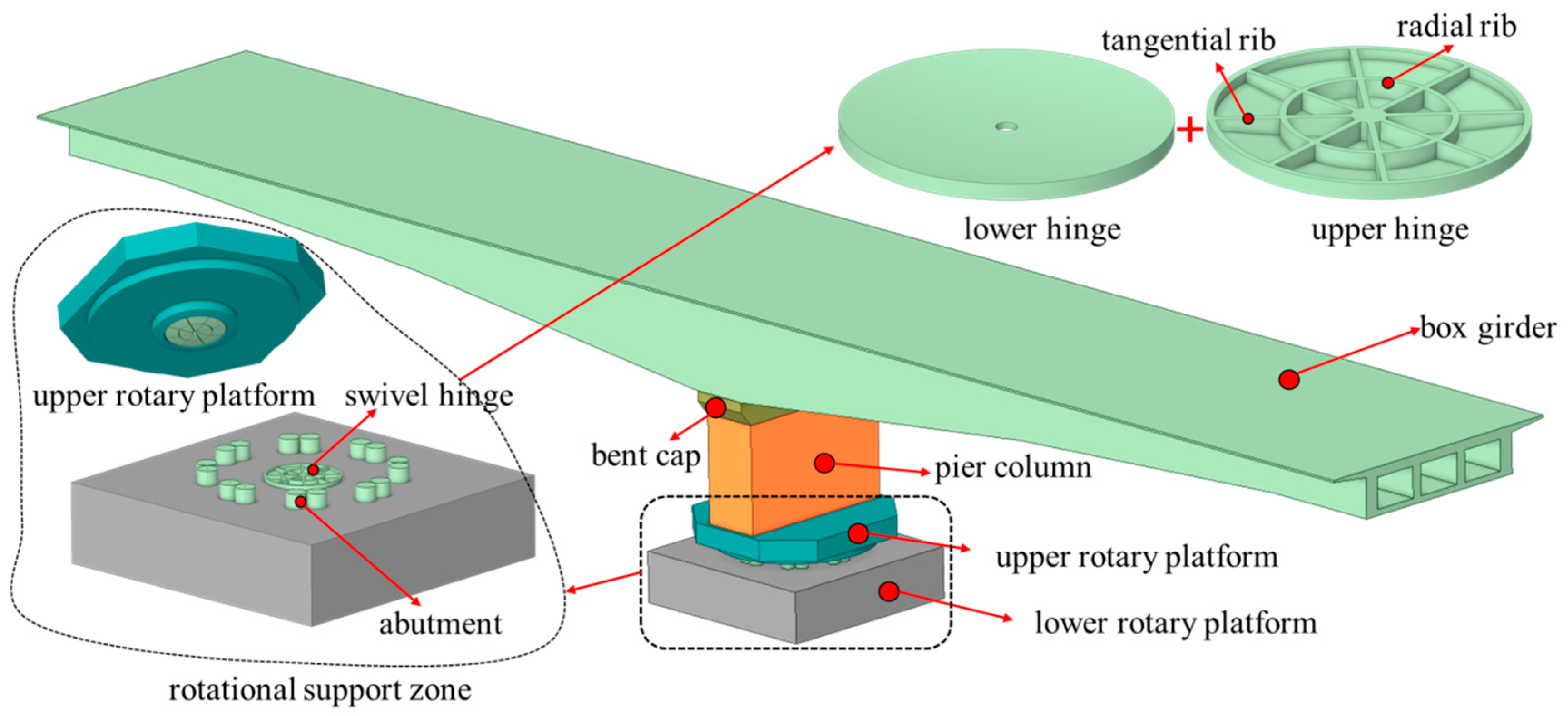
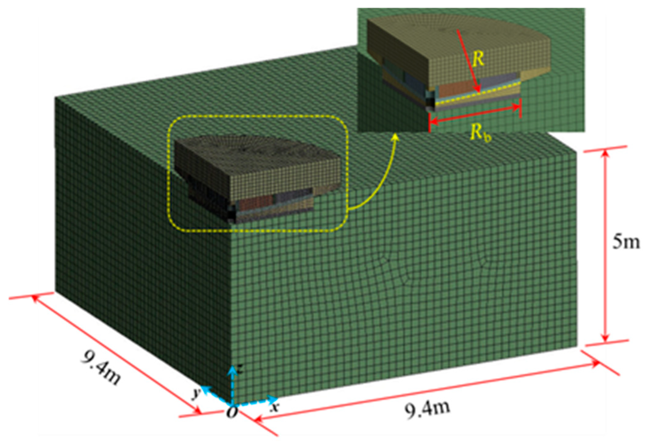
2. Finite Element Model and Validation

2.1. Model Overview

This study focuses on large-tonnage rotary bridges spanning the South-to-North Water Diversion Project along the Jiaozuo to Tanghe Expressway, material and equipment are sourced by Installation Engineering Co., Ltd. of CSCEC 7th Division, Zhengzhou China. The finite element model of the rotary bridge project is established by using the Ansys 2020 R2, which is an important method used to calculate the contact force. The model is built with reference to the actual project size and parameters. Upon the removal of the supports and the dismantling of the temporary stabilizing structures, a bridge under rotational construction will temporarily remain in a static state. During this phase, all rotational loads will be borne by the central pivot hinge, which serves as the load-transferring mechanism between the rotational T-structure and the lower turntable and facilitates the rotation process. From the perspective of the effects of force, the presence of the central hinge has a significant impact on the anti-overturning performance of the rotating T-structure and the stress characteristics of the lower turntable. On the one hand, this is due to the frictional torque generated between the upper and lower pivots, which constitutes a major contributor to the anti-overturning torque of the T-structure. The magnitude of the frictional torque is closely related to the critical geometric dimensions of the hinge. On the other hand, the differences in geometric dimensions between the central pivot and the lower turntable result in localized force phenomena at the lower turntable, leading to notable stress concentration effects.
A cross-sectional diagram of the spherical hinge and schematic diagrams of key geometric dimensions are illustrated in Figure 2 and Figure 3, respectively. Based on a geometric analysis of the central pivot, it is discerned that the spherical radius (R), supporting radius (Rb), and spherical crown height (H) are three crucial geometric dimensions determining its structural configuration. The interrelation between those three effective parameters is proposed in terms of Equations (1) and (2).
R = R b 2 + H 2 2 H
lim R H = lim R ( R R 2 R b 2 ) = 0
Equation (2) elucidates that, as the radius (R) tends towards infinity, the spherical crown height (H) approaches zero. Consequently, the central pivot gradually transitions from a spherical hinge to a planar one. In geometric terms, a flat pivot can be conceptually regarded as a spherical pivot with an infinitely large spherical radius (R). Thus, there exists continuity in the geometric relationships between planar and spherical hinges. Furthermore, it follows that any two out of the three mentioned dimensions uniquely determine the configuration of the hinge. Considering the direct influence of the spherical pivot’s radius (R) and supporting radius (Rb) on the structural forces of the rotating body, these two dimensions are selected as key parameters for investigating the impact of pivot forms on the structural behavior of the rotating system.
The numerical model of the rotating structure analyzed in this paper is based on the South-to-North Water Diversion Extraordinary Rotational Bridge, spanning the Fangcheng to Tanghe Section of the Jiaozuo to Tanghe Expressway. The structural composition, from bottom to top, includes the lower turntable, steel spherical hinge, steel-reinforced concrete support abutments, upper turntable, piers, and a variable-section box girder. The rotating T-structure is symmetrical about the center of the spherical hinge. The longitudinal total length of the box girder is 160 m, with the lower turntable having a height of 5 m. The overall height of the upper turntable is 3.7 m, while the pier columns stand at a height of 2.5 m. The cross-sectional height of the 0# box girder located at the top of the pier column is 10.5 m. The lower turntable utilizes C55 concrete and serves as the foundation to support the entire weight of the rotating structure. Upon the completion of rotation, it collaborates with the upper turntable to form the foundation of the bridge. The lower turntable is equipped with a rotation system comprising a lower spherical hinge, support legs, and a circular slide track, as well as jacks and reaction seats used for rotating the structure. The hinge has a spherical radius (R) of 13.5 m and a supporting radius (Rb) of 2.25 m. The spherical pivot employs an integral cast structure utilizing steel grade Q355D. The static friction coefficient for the contact surface of the hinge is set at 0.10, while the dynamic friction coefficient is 0.06. Based on the analysis of the geometric dimensions of the central pivot mentioned above, corresponding numerical models are established for the spherical radius (R) and supporting radius (Rb), as shown in Table 1, Table 2 and Table 3. The ratio of radius to height (α) in the tables represents the ratio of the supporting radius to the spherical crown height, indicating the curvature level of the contact surface of the central pivot. A higher value of α implies a pivot form closer to that of a flat pivot.
The primary focus of this study lies in the analysis of the impact of localized compression and stress concentration on the lower turntable induced by rotational loads under different dimensions of hinges, as well as differences in the stability of the rotational T-structure. Secondary factors, including sliders between the upper and lower hinges, shear-resistant steel plates, vibration-compaction holes, and pin axles [22,23], are considered to have minimal impact on the analysis. Furthermore, incorporating these elements into the solid model would substantially increase the numerical model’s element count without yielding significant advantages for the analysis objectives. Therefore, these secondary factors are excluded from this study.

2.2. Model Validation

The concrete utilized in the bridge exhibits a strength grade of C55, and its stress–strain relationship under uniaxial loading is illustrated in Figure 4. The parameter values are derived in accordance with the specifications outlined [24]. As for the central pivot, Q355D steel is employed, characterized by a Young’s modulus of 200 GPa, a Poisson’s ratio of 0.25, and a yield strength of 355 MPa. The steel material behavior is modeled using an ideal elastoplastic model.
According to engineering design experience, the vertical stress on the contact surface of the central pivot is a crucial indicator in determining the dimensions of a hinge. Its value can be obtained through analytical solutions derived from elastic mechanics, and numerous scholars have conducted in-depth research on this aspect. Simplified the force acting on the contact surface of the spherical hinge as an approximately concentrated force model applied on the boundary of a semi-planar body [11]. The vertical stress calculation formula for the contact surface of the spherical hinge was derived through static equilibrium conditions, as expressed in Equation (3). Mo [22] employed the principles of elastic deformation coordination criteria to derive the theoretical calculation formula for the vertical stress on the contact surface of the hinge, as presented in Equation (4). Presently, the design of swiveling hinges (spherical hinge and plane hinge) commonly refers to the calculation of the vertical stress on the hinge contact surface in accordance with [25], as illustrated in Equation (5).
σ v 1 = 3 cos 2 θ 2 [ 1 ( R 2 R b 2 ) 3 / 2 / R 3 ] F π R 2
σ v 2 = F 2 π R b 2 ( 1 r 2 R b 2 ) 1 / 2
σ v 3 = F π R b 2
The meanings of the parameters in Equation (3) to Equation (5) are depicted in Figure 5. The theoretical calculation formula regarding the vertical stress on the contact surface of the ball joint mentioned above can be employed to verify the reliability of the finite element model. The current study selects the model “M-Rbs2.25-R13.5”, established based on the Jiaozuo to Tanghe Expressway—Fangcheng to Tanghe cross-section of the South-to-North Water Diversion Grand Bridge, to verify the reliability of the finite element model. The quarter model of the rotational support zone is depicted in Figure 6. Considering only the self-weight of the bridge under the actual loading conditions, the rotational load is approximately 25 × 104 kN. Fixed constraints are applied to the underside of the lower turntable.
Figure 7 depicts a contour map of the vertical stress on the lower half of the spherical hinge for the model “M-Rbs2.25-R13.5”. The deep-blue region corresponds to the positions of the radial and annular ribs on the upper half of the hinge. Due to the significantly higher Young’s modulus of steel compared to concrete, the stress values in these regions are greater under the same strain conditions. In the figure, Path1 represents the trajectory along the non-radial ribs on the contact surface of the spherical hinge, while Path2 corresponds to the trajectory along the radial ribs on the contact surface. As depicted in Figure 8, the simulated values of vertical stress distribution along Path1 and Path2 are compared with the calculated values from the three aforementioned theoretical formulas. It can be observed that the theoretical calculations for the vertical stress distribution on the contact surface of the spherical hinge are generally consistent with the numerical simulation results. The results from Equations (3) and (5) exhibit a minor discrepancy, with their values closely aligning with the vertical stress distribution beneath the ribs (Path2) on the contact surface. On the other hand, Equation (4) concurs with the vertical stress distribution in the non-rib region (Path1) of the contact surface.
A finite element model is established based on actual dimensions, utilizing hexahedral meshing. The load of the rotating structure is transferred through the upper and lower spherical hinges to the contact surface [26]. The friction between the contact surfaces provides the anti-overturning torque for the balance of the T-structure during the rotation process, while also affecting the ease of achieving the rotation. For concrete spherical hinges, the contact area between the upper and lower hinges is greatly affected by on-site construction errors. By requiring the contact ratio after grinding to exceed 75% for steel spherical hinges, due to the customized construction completed in the factory, their contact surfaces are relatively smooth, and the matching contact ratio between the upper and lower hinges is easy to control. Therefore, in this paper, it is assumed that the upper and lower hinges are in 100% contact before the load is applied. The workbench provides six types of contact to adapt to different working conditions. According to the actual working conditions of the rotating construction bridge, the contact mode between the upper and lower hinges is defined as frictional (surface) contact, that is, the upper and lower hinges can achieve normal separation and tangential sliding based on the way the external forces act. When the tangential component force generated after the external force acts exceeds the maximum friction force in that direction, the equation can slide; moreover, the contact of other structural members is uniformly simplified to bonded contact, coupling all degrees of freedom of the nodes between the two contact surfaces within the contact range, that is, no relative sliding or separation occurs between the contact surfaces. The main load borne by the spherical hinges and the lower turntable is still the self-weight of the rotating structure; in addition, the weight of the other auxiliary facilities, such as that of construction equipment, is relatively minimal compared to the self-weight of the rotating structure (2.5 × 10⁵ kN), hence only the self-weight load of the rotating structure is considered. At the same time, based on the actual boundary conditions of the rotating structure, fixed constraints are applied at the bottom of the lower turntable.
In the sensitivity analysis of mesh size, the load and boundary conditions were kept unchanged, and a total of seven mesh sizes of 0.5, 1.0, 1.5, 2.5, 5, 10, and 20 mm were selected for simulation research. The results show that when the mesh size increases to more than 2 mm, the finite element numerical results begin to fluctuate greatly, and the mesh division is rough and the finite element simulation results are inaccurate; therefore, the mesh size used is 1.5 mm. Guo [27] also carried out static characteristic analysis and structural optimization on the key components of the rotating spherical hinge. The vertical pressure stress data on the contact surface of the upper and lower spherical hinge can also be used as the verification of the numerical simulation of this paper. The comparative verification results are shown in Figure 9.
Therefore, it can be concluded that the parameters of the finite element model are reasonably set, and the computational results are deemed suitable for further analysis.

3. Impact of Spherical Hinge Dimensions on the Anti-Overturning Performance

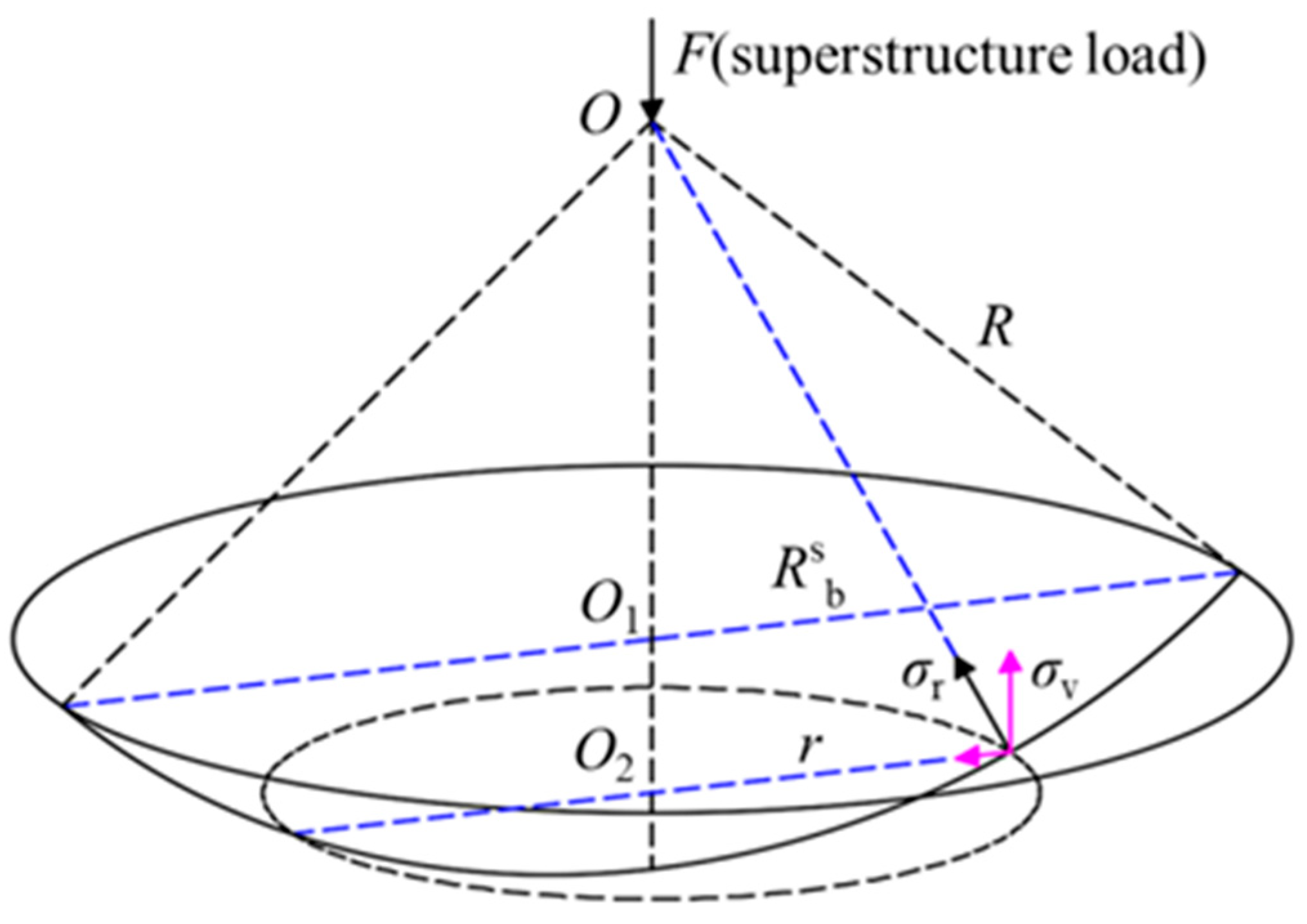
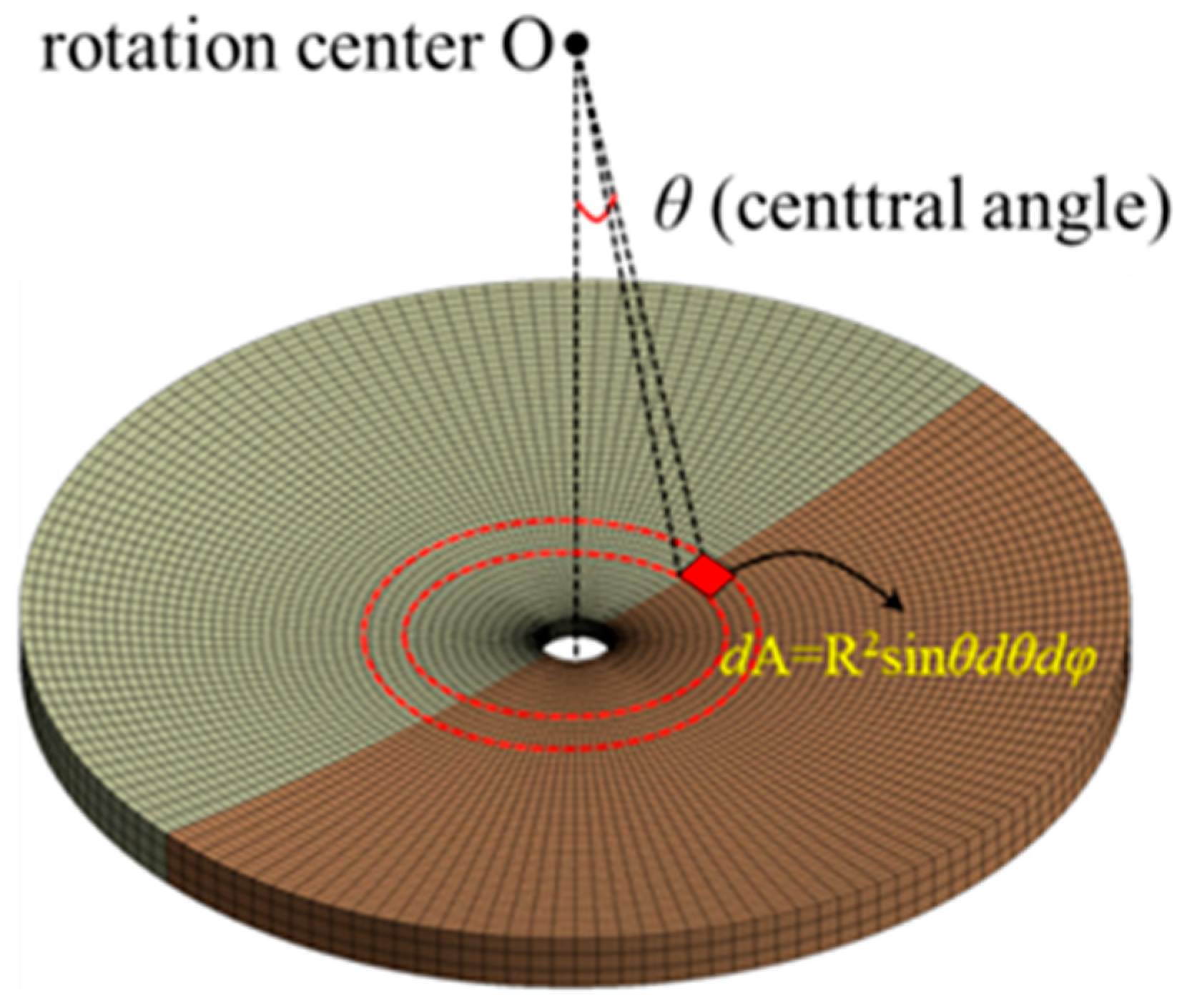
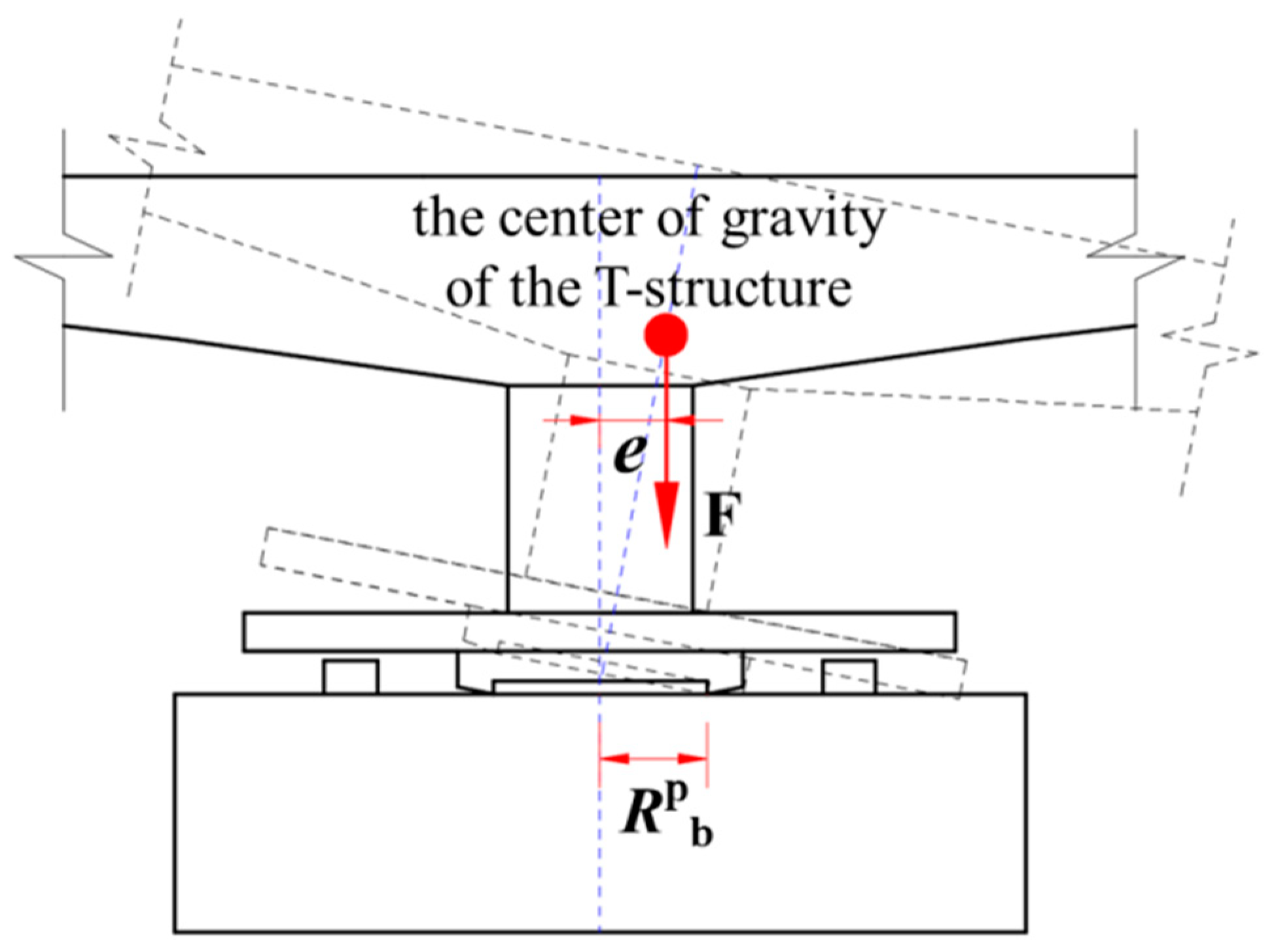
3.1. Theoretical Analysis of Anti-Overturning Performance

In the bridges constructed using the flat rotation method, the transverse span is typically symmetric, with its transverse width being smaller compared to its longitudinal length. Consequently, structural overturning in the transverse direction is less likely to occur. However, due to environmental constraints inherent to the construction of swiveling bridges, structural asymmetry may occur in the longitudinal direction. Additionally, the asymmetrical construction loads on both sides of the pier for the T-structure’s girders may lead to significant unbalanced moments. For rotational bridge structures with central support, when there is a tendency to tip, or actual tipping occurs in the rotational T-structure, the torque generated by the frictional force in the opposite direction of the tipping between the hinge contact surfaces becomes the main source of the T-structure’s resistance to tipping torque.
The force at any point on the contact surface of a spherical hinge can be resolved into three orthogonal directions—i, j, and k—as illustrated in Figure 10. Here, the i direction denotes the radial force directed towards the center of the spherical hinge. According to the relevant theories of frictional forces, when T-shaped structures experience overturning, the direction of frictional forces at various points on the hinge contact surface is opposite to the sliding direction within the j and k plane at that point. The overturning resistance moment generated by these frictional forces is expressed in Equation (6).
T s a = 0 2 π 0 α μ s σ r R 3 sin θ d θ d φ
where Tsa represents the anti-overturning moment produced by the spherical hinge, μs is the static friction coefficient, σr denotes the radial stress at any point on the contact surface, and the other parameters are as illustrated in Figure 10. By discretizing the contact surface of the spherical hinge into an adequate number of nodes and elements, as depicted in Figure 11, the discrete expression for Equation (6) is given as follows:
T s a = i = 1 n μ s σ r i R 3 sin [ θ 0 + ( n 1 ) θ i ] θ i φ 0
In practical engineering, when external factors such as asymmetric structural design and unbalanced construction loads cause the upper rotational load line to deviate from the center of the spherical hinge (as illustrated in Figure 12), an overturning moment is subsequently generated. The expression for this overturning moment is given with Equation (8).
T s o = F e
where Tso represents the overturning moment of the T-structure. Based on this, the equilibrium states of the T-shaped assembly can be classified into the following three scenarios:
{ T s o < T s a ,   stable   state T s o = T s a ,   critical   state T s o > T s a ,   unstable   state .
According to the aforementioned theoretical analysis related to the anti-overturning of the T-shaped assembly, the critical eccentricity escr can be utilized to characterize the anti-overturning performance of the T-shaped structure under specific hinge configurations and dimensions. Its calculation is expressed with Equation (10).
e s c r = T s a F
For bridges constructed with planar hinges, if the resultant force line of the upper structure’s self-weight and various construction loads exceeds that of the circular range of the planar hinge, the T-shaped assembly will experience overturning. Hence, the critical eccentricity for overturning (epcr) in the flat hinge system is equal to the support radius of the flat hinge, i.e., epcr = Rpb. A schematic illustration of the overturning of the upper rotational structure with a load (F) and a support radius (Rpb) for the planar hinge is depicted in Figure 13.

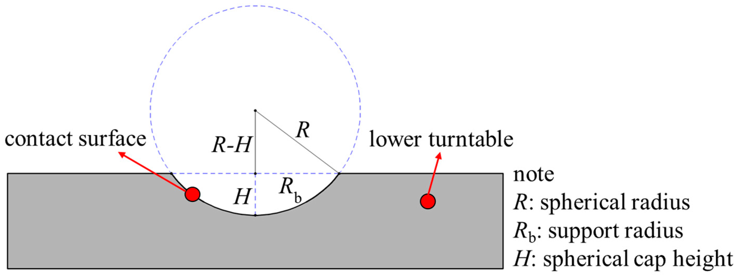
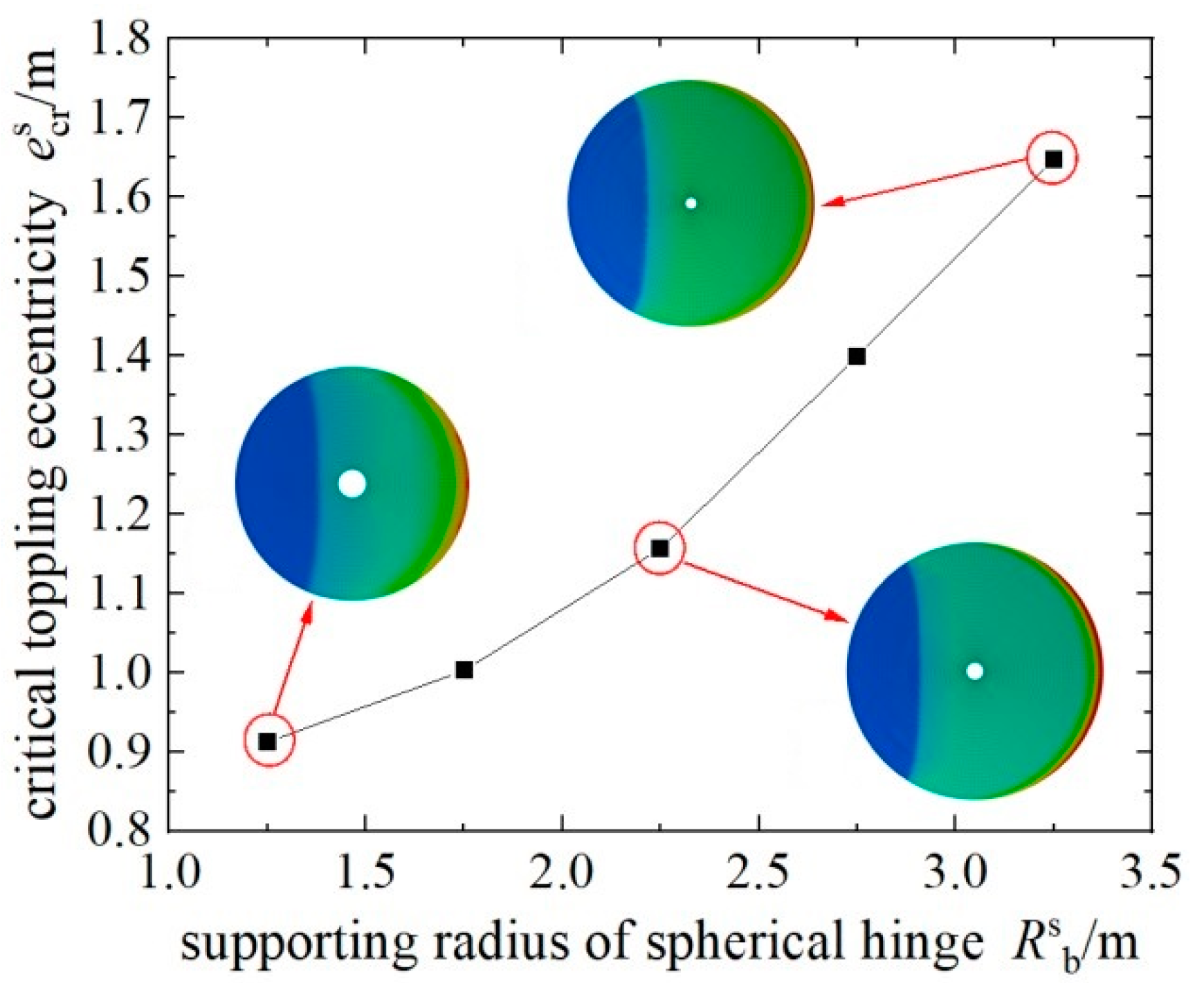
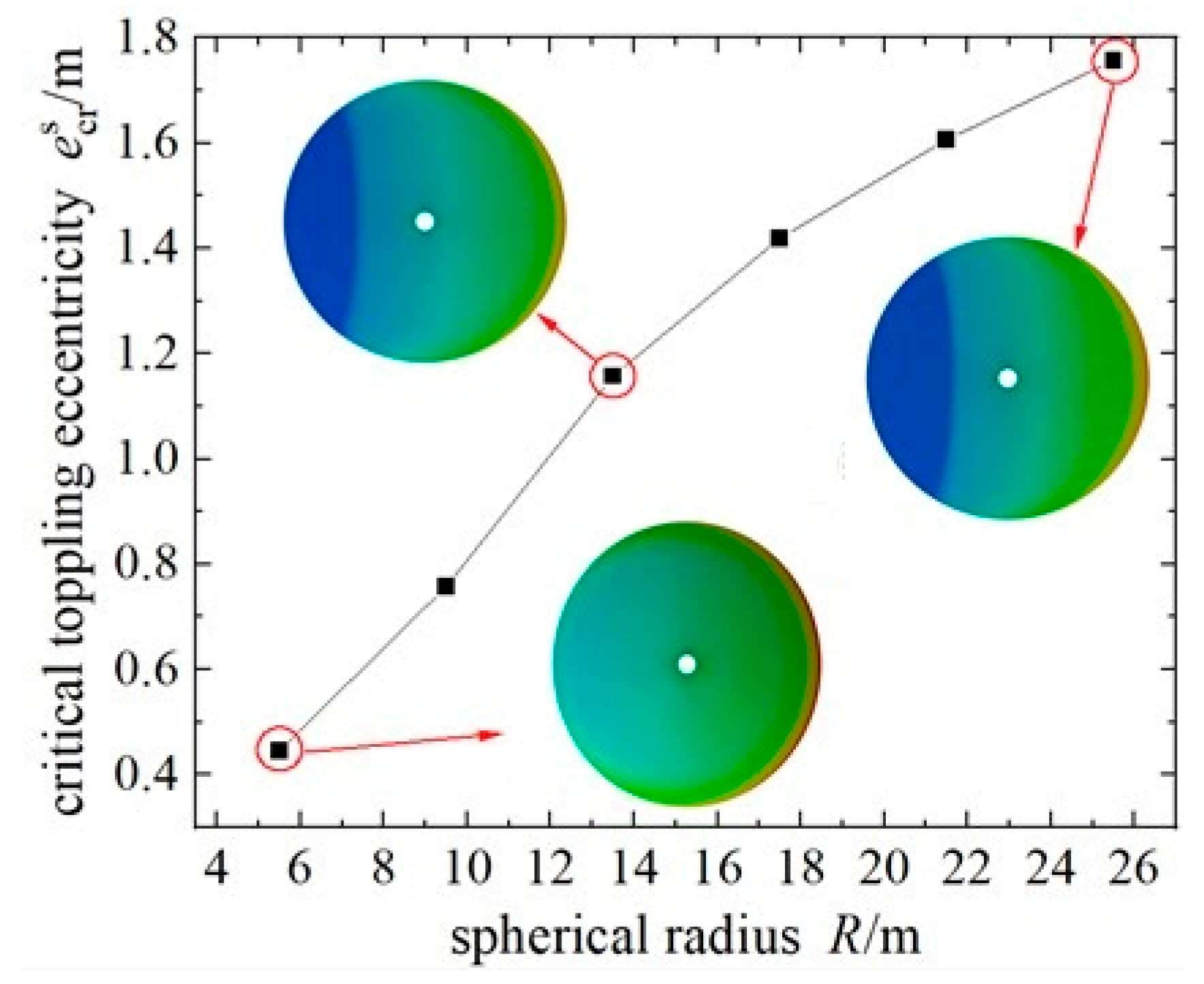
3.2. The Impact of Ball Joint Supporting Radius and Ball Joint Spherical Radius

As depicted in Figure 10, the sum of the moments exerted by the tangential friction forces at all points on the contact surface of the hinge creates the maximum static friction moment Ts that the T-structure must overcome to initiate rotation. Once the T-structure begins to rotate, the static friction moment transforms into a dynamic friction moment Tm. The relative magnitudes of these two critical moments determine the amount of kinetic energy supplied for the initiation and normal rotation of the T-structure. The theoretical calculation formulas for these moments are given as Equation (11) and Equation (12), respectively.
T s = 0 2 π 0 α μ s σ r R 3 sin 2 θ d θ d φ
T m = 0 2 π 0 α μ m σ r R 3 sin 2 θ d θ d φ
where μm represents the sliding friction coefficient of the ball joint contact surface.
The relationship between three critical torques and the rotating structure’s tonnage, as derived from theoretical calculations and finite element analysis, is depicted in Figure 14. It is evident that all three critical torques exhibit linear relationships with the rotating body’s tonnage. Due to the substantial stiffness and strength of steel spherical hinges, under the load conditions typical of commonly encountered heavy-tonnage rotational construction bridges, the vertical stress on the contact surface of the upper and lower ball joints exhibits a linearly increasing trend with the increase in the load of rotational structures. For subsequent studies on the critical eccentricity and strength safety performance of rotational bridge structures, a load of 2.5 × 10⁴ tons is selected for application to the corresponding structure.
The relationship between the supporting radius (Rsb) of the spherical hinge and the critical eccentricity (escr) of the overturning of the T-structure is illustrated in Figure 15. It is evident that the critical eccentricity (escr) significantly increases with the augmentation of the supporting radius. For the rotating T-structure, denoted as “M-Rsb1.25-R13.5”, with a static friction coefficient of 0.1 on the contact surface, the approximate critical eccentricity for overturning is 0.91 m. Therefore, under conditions excluding extreme scenarios, such as strong winds or highly asymmetric structures, the controlled range for the eccentricity of the rotating T-structure in rotating body bridge constructions, falling within the 5 to 15 cm range, exhibits a considerable safety margin. The cloud diagram in the figure depicts the vertical stress distribution on the lower hinge when subjected to the load of the rotating body at the corresponding critical eccentricity. The blue region signifies that the upper and lower hinges have separated and are no longer in contact. The maximum vertical compressive stress experienced by the spherical hinge due to the eccentric loading of the rotating body is 203 MPa, which remains below the yield stress of the steel ball joint, set at 355 MPa.
As the supporting radius of the spherical hinge decreases, the rate at which the critical eccentricity (escr) for the overturning of the T-structure diminishes and gradually approaches a more subdued pace. In accordance with the geometric relationship between the spherical hinge and the planar hinge, at a specific spherical hinge radius (R), as the supporting radius (Rsb) decreases, the spherical crown height of the ball joint decreases, resulting in an increase in the crown-height-to-radius ratio (α). Consequently, the geometric structure of the ball joint gradually approaches that of a planar hinge. Hence, at relatively smaller supporting radii for the ball joint, the critical eccentricity for the overturning of the T-structure in both the planar hinge and spherical hinge systems exhibits minimal disparity. Conversely, as the supporting radius increases, the discrepancy in the critical eccentricity for the overturning of the T-structure between the two hinges becomes more pronounced. Simultaneously, it is evident that the critical eccentricity for the overturning of the T-structure (escr) in the spherical hinge system consistently remains smaller than the critical eccentricity for instability in the planar hinge system (epcr = Rpb). Therefore, the anti-overturning performance of the planar hinge rotating body structure surpasses that of the spherical hinge with an equivalent supporting radius.
The relationship curve between the spherical radius (R) of the hinge and the critical eccentricity (escr) for the overturning of the T-structure is depicted in Figure 16. For the rotating body structure denoted as “M-Rsb2.25-R5.5”, with a supporting radius of 2250 mm and a spherical radius of 5500 mm, the critical eccentricity (escr) is determined to be 44.6 cm. As the ball joint radius increases, the critical eccentricity for the overturning resistance of the T-structure exhibits nonlinear growth, with the rate of increase gradually diminishing. As the ball joint radius (R) gradually increases, the spherical crown height (H) decreases, and the structure of the spherical hinge approaches that of a planar hinge. Therefore, the critical eccentricity for the overturning resistance of the T-structure should converge to that of the corresponding supporting radius. In the limit of R→+∞, it holds that escr = Rpb. On the other hand, the reduction in the ball joint radius (R) implies a shortened lever arm for the static friction torque resisting the overturning of the T-structure. This results in a decrease in the overturning resistance torque, consequently leading to a reduction in critical eccentricity.
The cloud diagram in the figure illustrates the vertical stress distribution on the lower spherical hinge when subjected to the load of the rotating body at the corresponding critical eccentricity. The blue region signifies that the upper and lower ball joints have separated and are no longer in contact. It is evident that, at relatively small ball joint radii (R), when the T-structure is in a critical overturning state, the upper and lower ball joints maintain complete contact. Therefore, in practical engineering, it is advisable to choose rotating joints with larger ball joint radii (R) to mitigate the risk of the sudden overturning of the T-structure. When subjected to the eccentric loading of the rotating body, the maximum vertical compressive stress experienced by the spherical hinge is 65 MPa, remaining below the yield stress of the steel ball joint.
Vertical stress contour maps of the lower half hinge of the rotating T-structure, employing a planar hinge at the critical overturning state, are illustrated in Figure 17a–e. In the figure, the blue regions indicate the separation of the lower turntable, signifying a detachment where no contact is maintained. It can be observed that, at the critical overturning state, different support radii of the upper and lower hinges experience partial detachment. At this juncture, the maximum vertical stress for the hinge with the minimum support radius is recorded at 180 MPa, a value significantly below its yield stress.

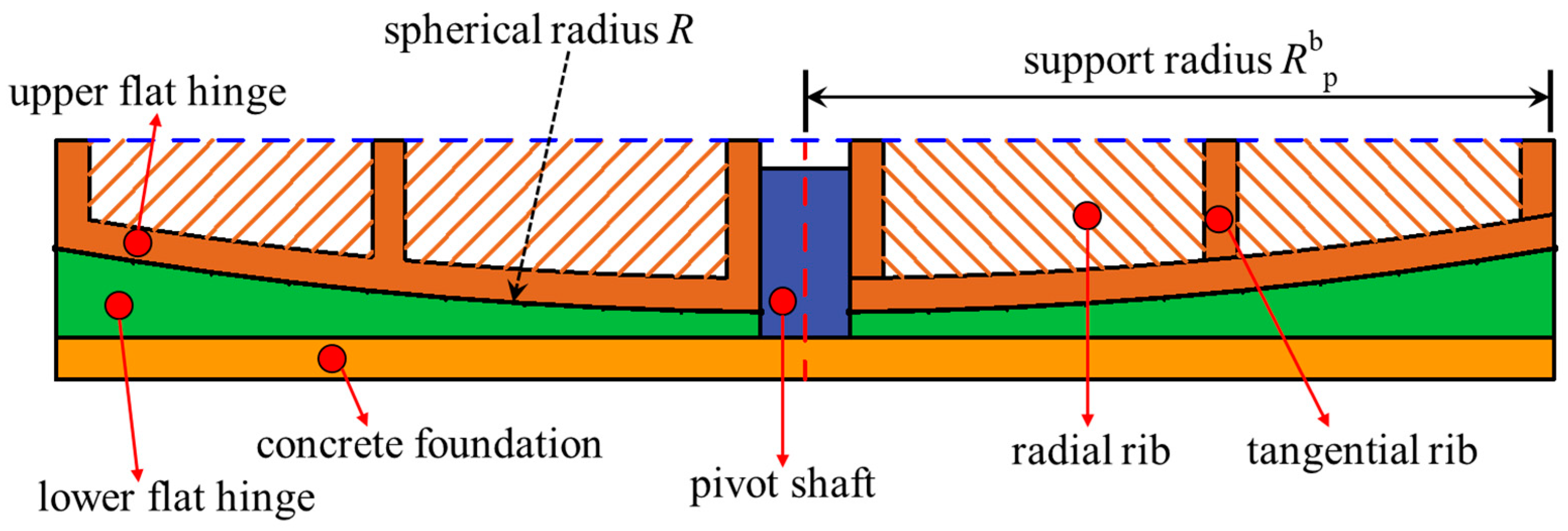
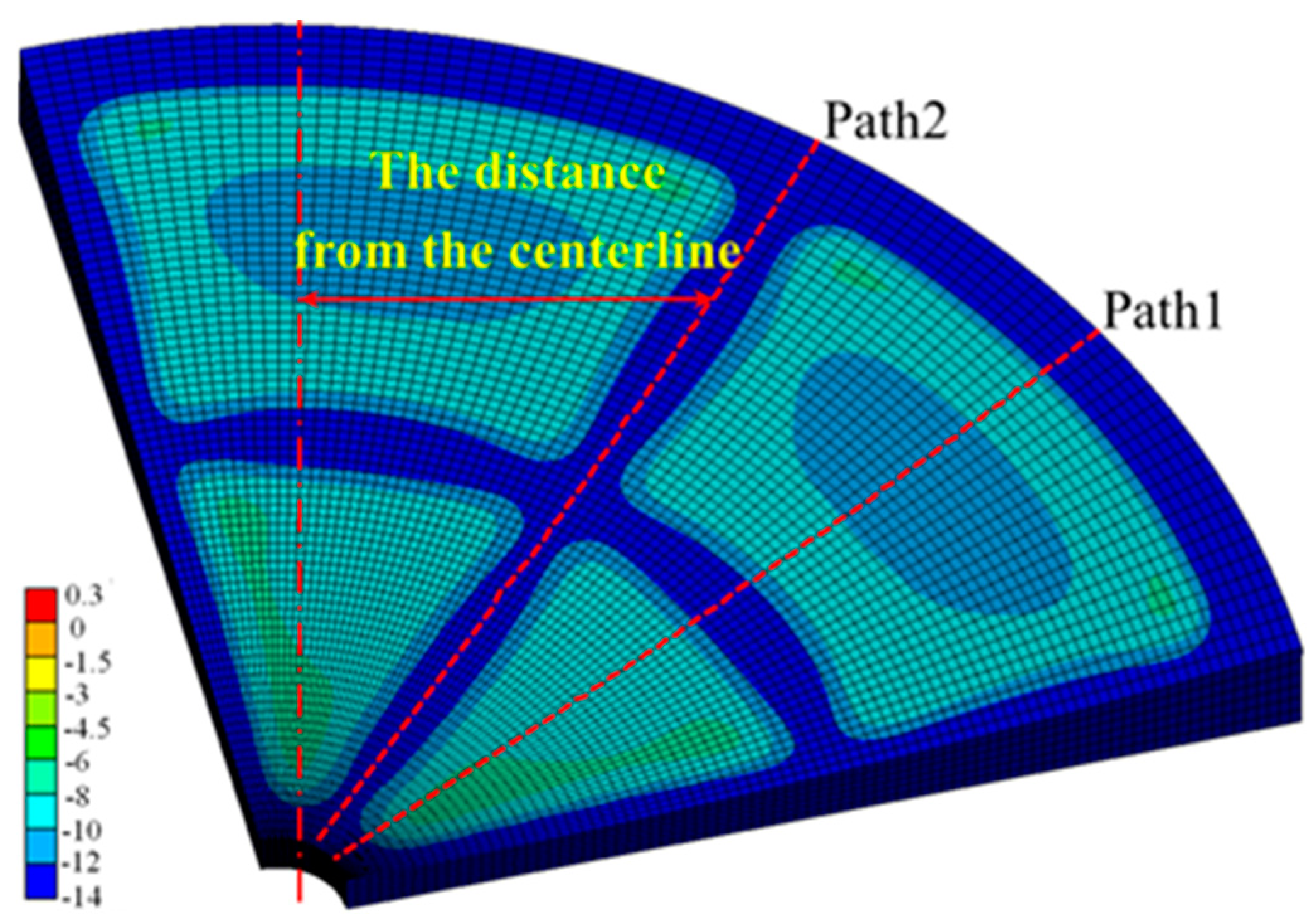
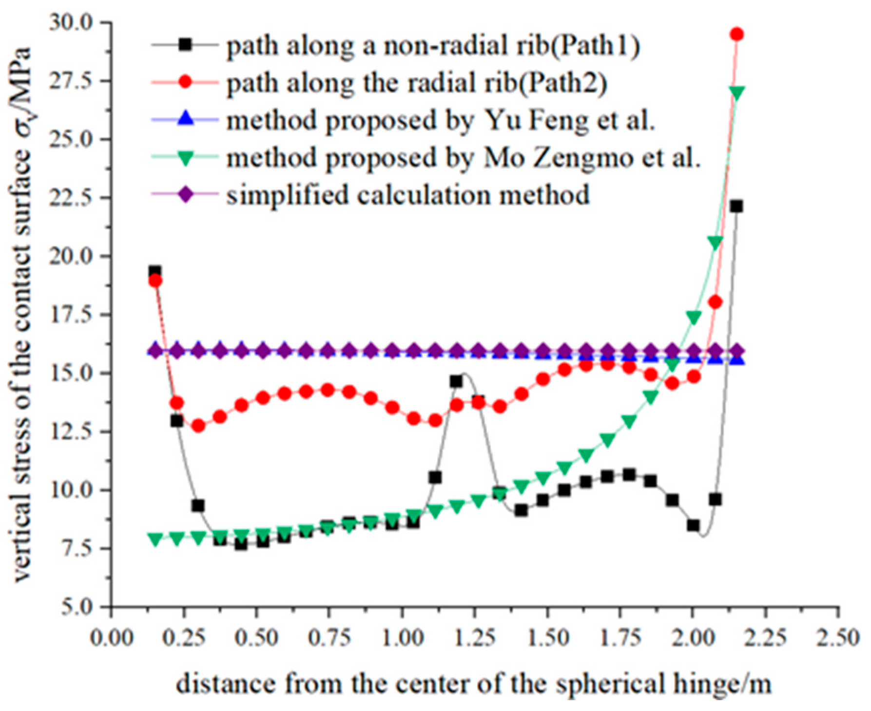
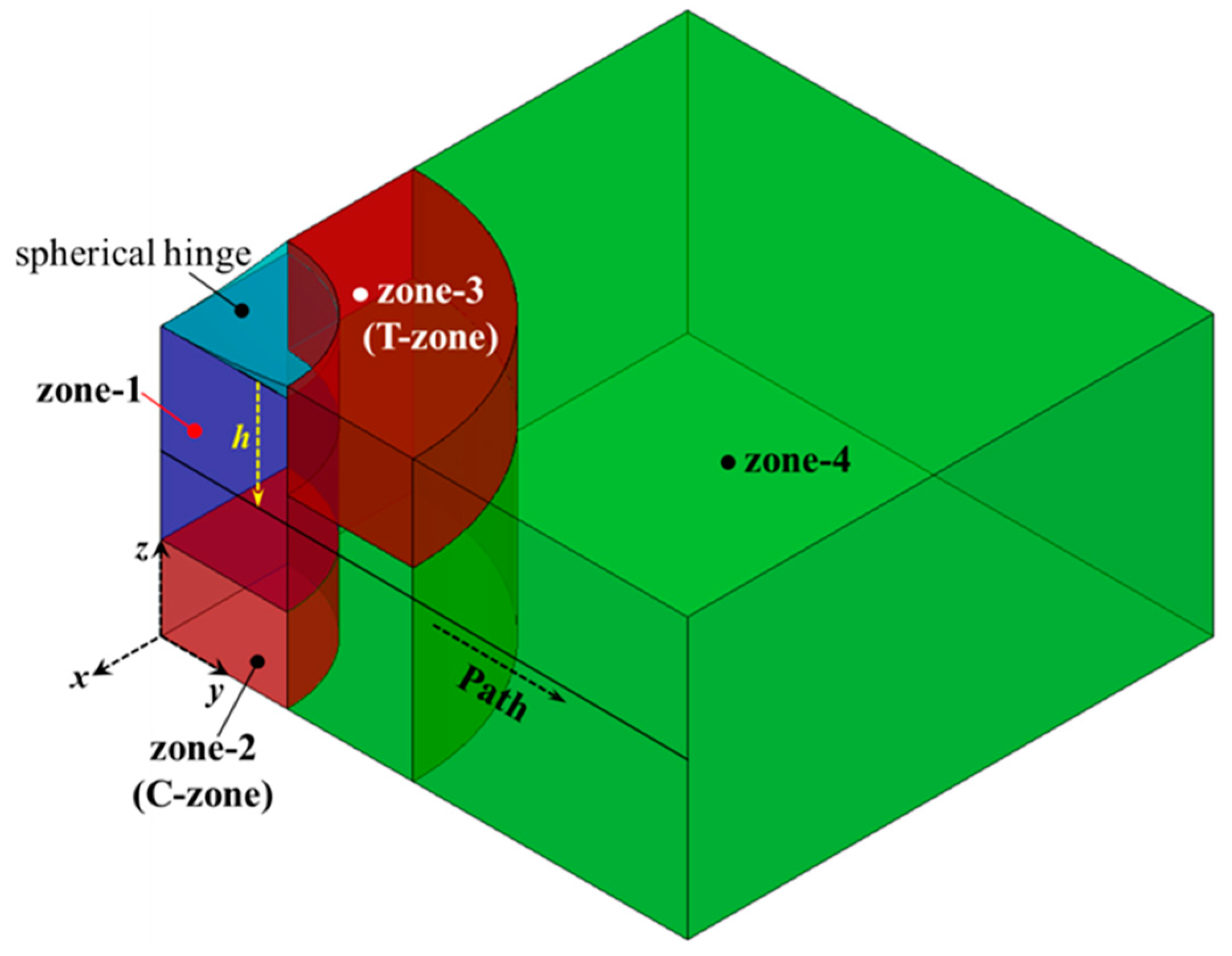
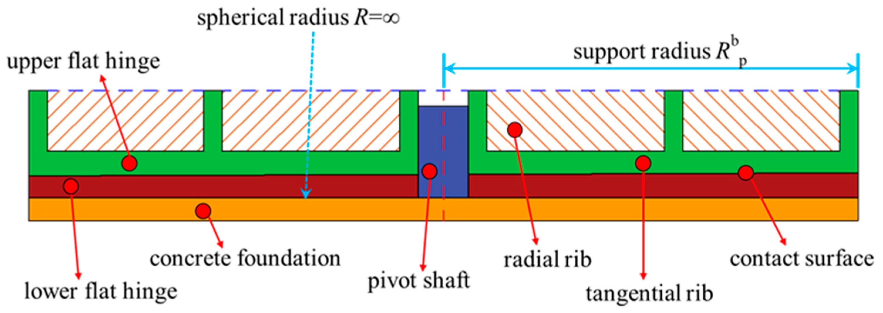
4. The Influence of Hinge Dimensions on the Lower Turntable

4.1. Local Compression of the Lower Turntable and the Ottosen Strength Criterion

The geometric differences in dimensions within the plane between the hinge and the lower turntable result in localized compression phenomena in the lower turntable. The magnitude of the geometric dimensions of the hinge directly influences the extent of localized compression in the lower turntable. This mode of loading often induces stress concentration, leading to localized structural failure well below its ultimate load-bearing capacity. Therefore, the design of the lower turntable must address the issues of localized compression caused by the hinge and the localized strength failure induced by stress concentration effects [7]. Under the predominant loading condition characterized by the rotational T-structure, localized sections beneath the hinge of the lower turntable are subjected to a triaxial compressive state, thereby exhibiting heightened strength relative to typical stress conditions. The surrounding regions are influenced by hoop effects, experiencing consequential tensile stress effects, thereby exacerbating crack control concerns in the lower turntable. To explore the influence of a varying support radius and spherical radius on the strength safety and corresponding failure modes of the lower turntable, the widely applicable Ottosen strength criterion for concrete materials is adopted for evaluation [23], as expressed in Equation (13).
f = a J 2 f c 2 + λ J 2 f c + b I 1 f c 1
where I1 represents the first stress invariant; J2 represents the second deviatoric stress invariant; fc denotes the uniaxial compressive strength of concrete (C55); and a, b, and λ are constants depending on the strength grade of the concrete. When f < 0 is true, it signifies the point is under safe stress conditions, f = 0 indicates that it is at a critical state, and f > 0 denotes that the point will experience failure under the corresponding stress conditions.

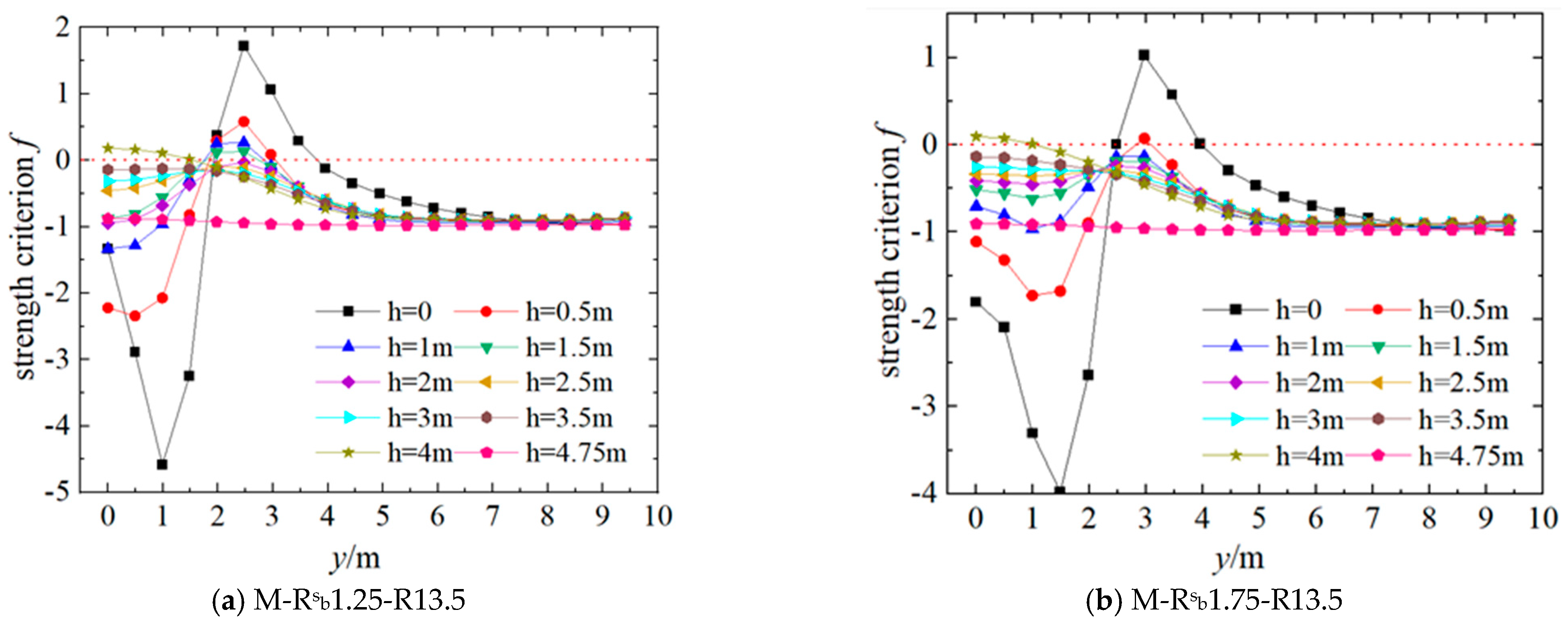
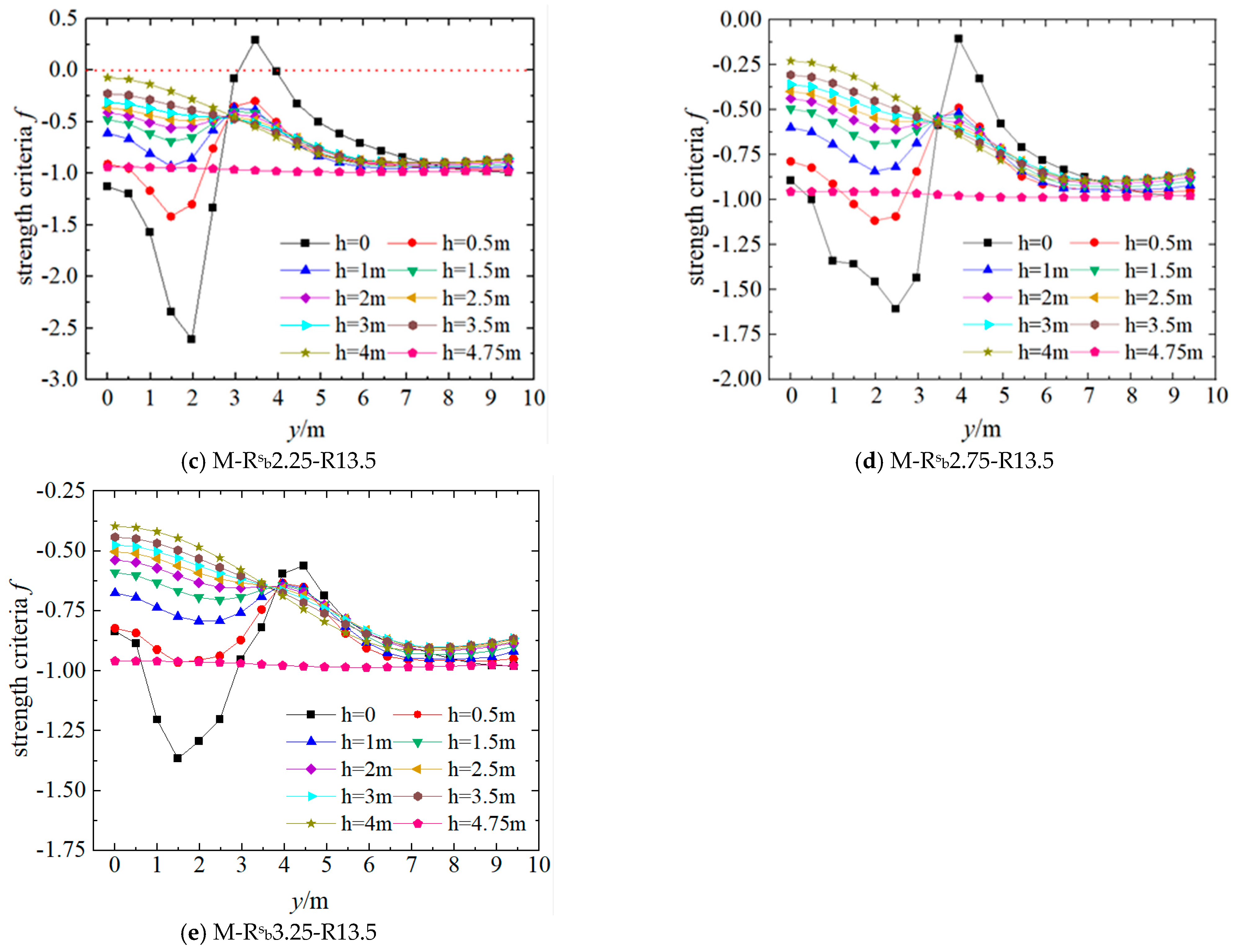
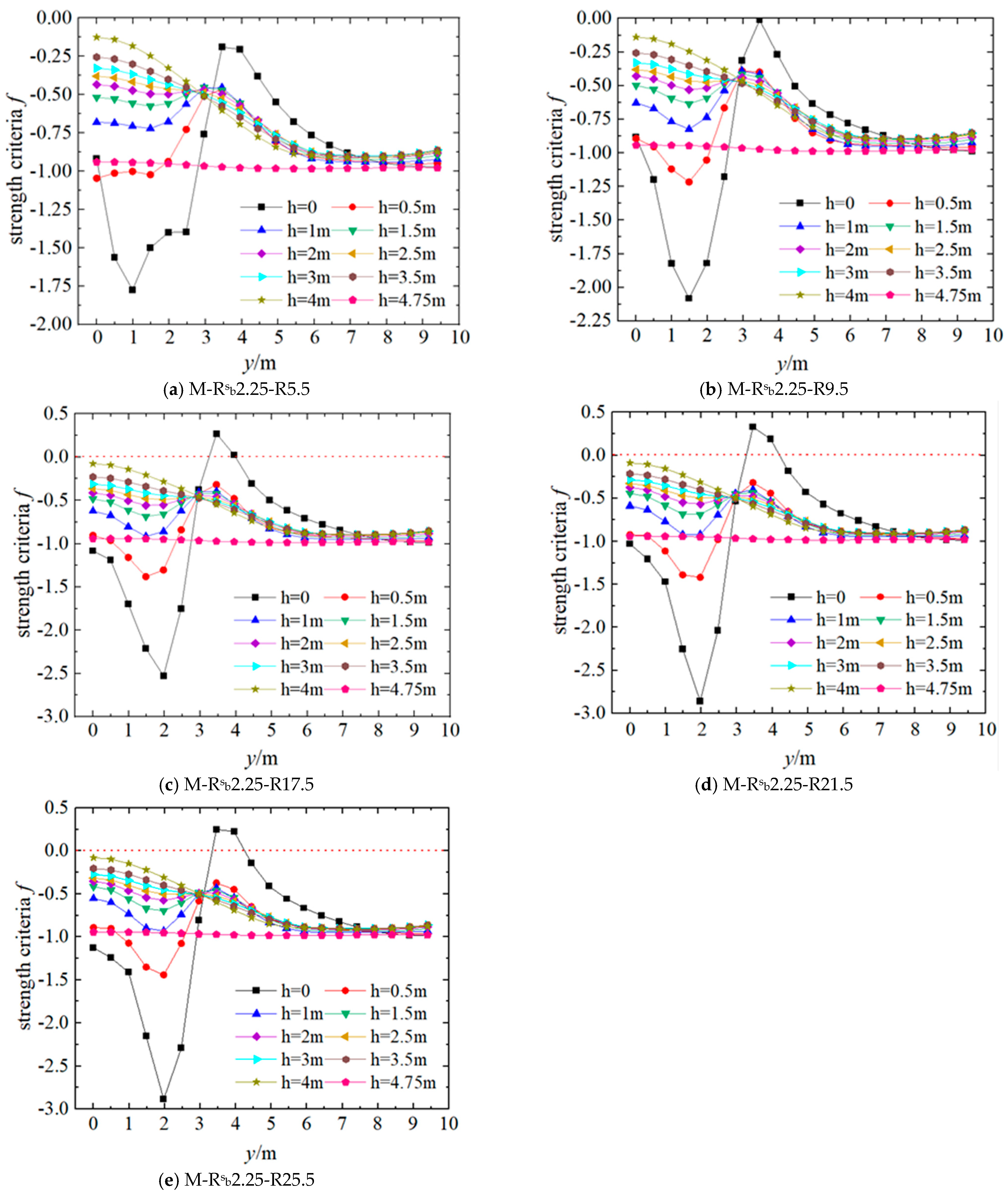
4.2. The Influence of the Support Radius

(1)
Spherical Hinge
Figure 18 depicts a quarter model of the rotational support region extracted from the rotating structure. Under a 25,000-ton rotational load, the strength safety condition of each point along the analysis path is evaluated using the Ottosen strength criterion, as depicted in Figure 19a–e. In the figure, h represents the vertical distance from the bottom surface of the lower hinge to the cross-section where the analysis path is located. In general, as the spherical hinge supporting radius increases, the area susceptible to strength failure within the lower turntable decreases. The localized compressive effect induced by the pivot gradually diminishes its influence on the strength safety of the lower turntable until it no longer causes strength failure. For the rotational support area with smaller supporting radii, the regions susceptible to strength failure are depicted as the T-zone and C-zone in Figure 18. The extent of these regions is closely associated with the magnitude of the T-structure load and the radius of the supporting radius.
The typical stress states of the nodes in the areas susceptible to strength failure on the lower turntable of the model M-Rsb1.25-R13.5, as depicted in Figure 19a, are illustrated in Table 4. It can be observed that, within the T-zone, the principal tensile stress at each point is significantly greater than that of the other two principal stresses. This region primarily experiences failure due to principal tensile stresses. Conversely, within the C-zone, although the points are under triaxial compressive stress, stress σ3 is notably higher than σ1 and σ2. Therefore, failure in this region is primarily governed by principal compressive stress. Due to the direct action of the rotational load transmitted by the spherical hinge and the hoop effect provided by the surrounding area of the lower turntable, the top region of the lower turntable beneath the hinge is under triaxial compressive stress. In this range, the hoop effect is significant, and the three principal compressive stress values are relatively close, indicating that the concrete is in a safe state. With the increase in h, the hoop effect on the concrete located directly beneath the pivot and near the bottom of the lower turntable (referred to as C-zone) weakens. At this point, although the points within the C-zone are under triaxial compressive stress state, the difference between σ3 and σ1 and σ2 becomes significant, leading to progressive strength failure.
Under localized loading from the T-structure, the concrete directly beneath the pivot undergoes compression, resulting in a vertical downward displacement. Consequently, the concrete in the upper region of the lower turntable, which is not directly compressed, experiences bending and tensile deformation. Under significant upper loading, this tensile stress in the bending region becomes considerable, potentially leading to primary tensile stress failure in the area. As h increases, the bending deformation gradually diminishes, reducing the likelihood of structural strength failure. Based on the analysis of the strength safety of the lower turntable and considering the structural symmetry and loading conditions, the lower turntable can be roughly divided into four zones, Zone-1 to Zone-4. The size of each zone primarily correlates with the dimensions of the hinge and the load from the T-structure.
  • Zone-1 is under triaxial compressive stress, with minimal difference among the three principal compressive stresses, making it less susceptible to strength failure.
  • Zone-2 (C-zone) is prone to primary compressive stress failure.
  • Zone-3 (T-zone) is susceptible to primary tensile stress failure.
  • Zone-4 experiences minimal stress response due to its distance from the direct-action area of the rotational load, making it less prone to strength failure.
(2)
Planar Hinge
Figure 20 presents a typical cross-sectional view of the planar hinge, while Figure 21a–e illustrates the assessment of the safety condition along the central axis of the lower turntable under a 25,000-ton load based on the Ottosen strength criterion. Regarding the influence of the planar pivot supporting radius on the strength safety of the lower turntable, there is no significant difference compared to that of the spherical hinge. As the radius of support of the planar hinge increases, the area of strength failure in the lower turntable induced by the concentrated load on the turntable decreases gradually until it disappears. Through the analysis of principal stresses at the failure nodes, it is evident that the failure mode of the lower turntable is similar to that of a spherical hinge. Specifically, primary compressive stress failure occurs in the C-zone, as depicted in Figure 18, while primary tensile stress failure occurs in the T-zone. Zone-1 and Zone-4, on the other hand, are less susceptible to strength failure due to the significant effect of hoop stress and their distance from the direct loading region of the turntable, respectively.

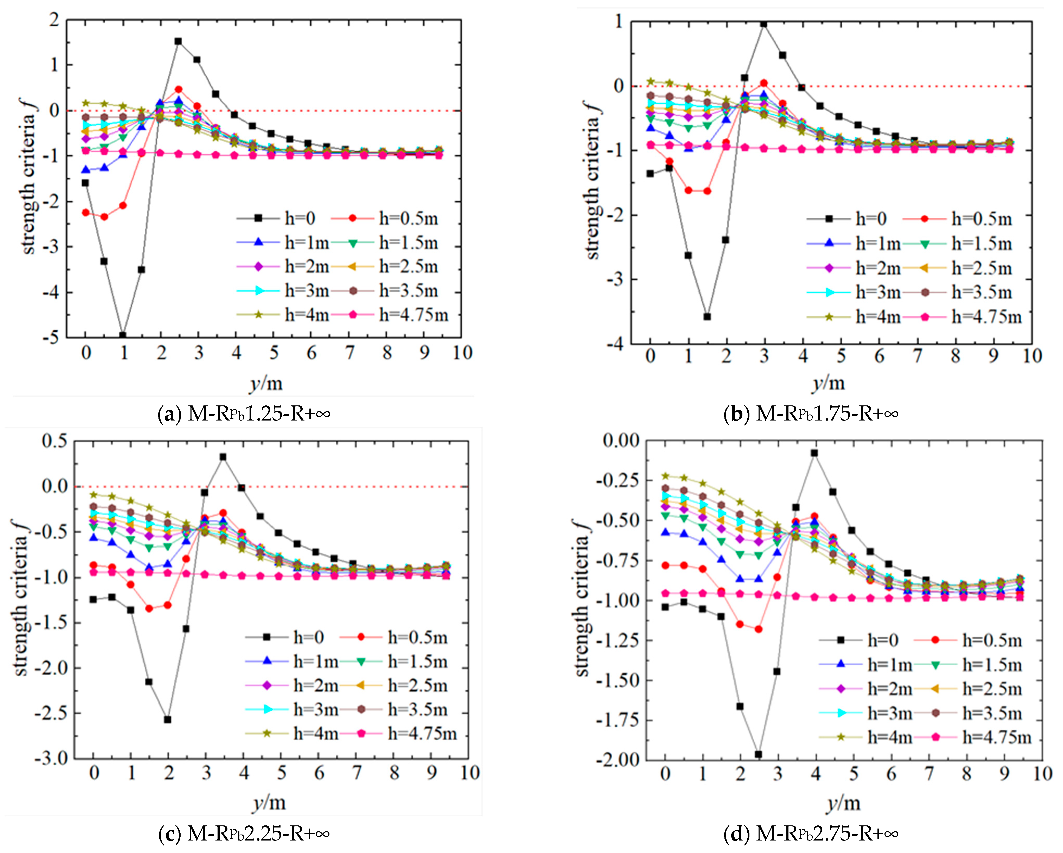
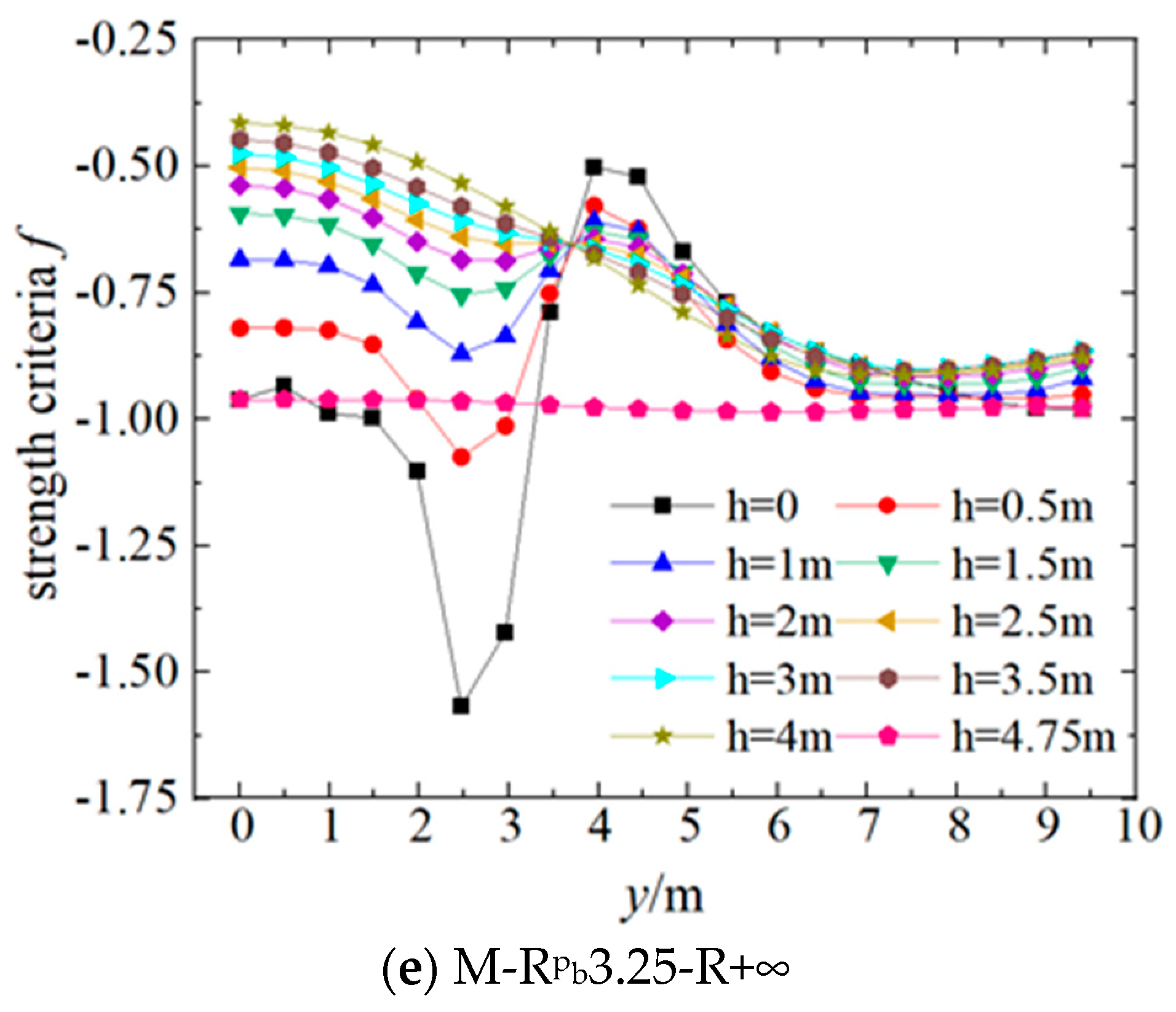
4.3. The Influence of the Spherical Radius

The spherical radius, denoted as R, represents the radius of the sphere where the upper and lower hinge contact surfaces lie. As R increases, as shown in Figure 3, the curvature of the circular contact line decreases. A planar hinge can be viewed as a spherical hinge with an infinitely large R value. Conversely, as R decreases, the curvature of the circular contact line increases. As illustrated in Figure 22, the depth value of the pivot contact surface penetrating into the lower turntable, denoted as the spherical crown height H, correlates with the severity of geometric transitions in regions subjected to the self-weight load of the upper T-structure. Theoretically, such transitions might exacerbate the stress concentration effects in the lower turntable under localized loading, thereby adversely impacting the structure itself.
Figure 23a–e depicts the strength safety conditions of the lower turntable along the central axis under a 25,000-ton load for different spherical radii. It is observed that the variation in the spherical radius has a minimal impact on the strength failure of Zone-2. Additionally, there is no occurrence of primary compressive stress failure near h = 4000 for different spherical radii. On the other hand, with the increase in the spherical radius, there is an increase in the number of nodes experiencing primary tensile stress failure in Zone-3 at h = 0. The reason for this phenomenon lies in the fact that the increase in R results in a decrease in the distance H between the cross-section at h = 0 and the top surface of the lower turntable. The settlement of concrete beneath the spherical hinge causes tension in the concrete around the top of the lower turntable, leading to primary tensile stress failure in this region. Moreover, the tensile effect becomes more prominent closer to the top surface of the lower turntable.

5. Conclusions

This study used ANSYS 2020 R2 to simulate the stress characteristics of a rotating structure under a 25,000-ton load with different support radii (Rb) and spherical radii (R). It explored the impact of these two factors on the anti-overturning performance of the T-structure and the strength safety performance of the lower turntable. The main research conclusions are as follows.
(1)
The support radius and spherical radius of hinges are two important factors influencing the critical eccentricity of the T-structure against overturning. The critical eccentricity (escr) for the overturning resistance of the T-structure increases with the increase in the support radius (Rb) and the spherical radius (R). With the decrease in Rb, the reduction rate of escr gradually decreases, while the increment of escr gradually decreases with the increase in R. The overturning resistance performance of the T-structure under planar hinges is superior to that observed under spherical hinges.
(2)
According to the intensity safety characteristics, the lower turntable can be divided into four areas, Zone-1~Zone-4. In Zone-2(C-zone), with the decrease in hinge bearing radius, there is main compression stress failure; in Zone-3(T-zone), main tensile stress failure may occur; while Zone-1and Zone-4 are not prone to strength failure. The ball hinge radius R has a great influence on Zone-3, and whether the main compressive stress failure occurs in Zone-2 is mainly determined by the rotating hinge bearing radius Rb.
(3)
The influence of the spherical radius (R) on the stress and strength safety of the lower turntable is primarily achieved by altering the height (H) from the pivot bottom to the top surface of the lower turntable, with a particularly significant effect on Zone-3. Therefore, whether principal compressive stress failure occurs in this zone is primarily determined by the support radius, with a lesser correlation to the spherical radius of the hinge.
(4)
In summary, this paper presents the design range of the support radii (Rb), spherical radii (R), and height (H), as well as the areas where the stress risk needs to be considered in the lower turntable. It provides a sufficient basis for the design of the bridge and guarantees the safety of bridge construction.

Author Contributions

Conceptualization, Z.Y.; Data curation, H.W.; Formal analysis, H.W. and G.S.; Funding acquisition, C.L.; Investigation, H.W.; Methodology, H.W.; Project administration, Z.Y. and H.W.; Resources, C.L. and Z.L.; Software, H.W.; Supervision, Z.Y., C.L. and Z.L.; Validation, H.W. and C.G.; Writing—original draft, H.W. and G.S.; Writing—review & editing, H.W. and C.G.; All authors have read and agreed to the published version of the manuscript.

Funding

The research described in this paper was financially supported by the China Construction Seventh Engineering Division Corp. Ltd.

Data Availability Statement

The original contributions presented in the study are included in the article, further inquiries can be directed to the corresponding author.

Conflicts of Interest

Authors Chunting Lu and Zhongming Li were employed by the company Installation Engineering Co., Ltd. of CSCEC 7th Division. The remaining authors declare that the research was conducted in the absence of any commercial or financial relationships that could be construed as a potential conflict of interest.

Nomenclature

SymbolDefinition
RSpherical radius
RbSupporting radius
HSpherical crown height
αThe ratio of radius to height
TsaThe anti-overturning moment produced by the spherical hinge
μsThe static friction coefficient
σrThe radial stress at any point on the contact surface
i, j, and kThree orthogonal directions
ORotation center
θCentral angle
ϕThe angle between the spherical hinge stress analysis point and the direction of a specific radius

References

  1. Wang, L.F.; Wang, E.Q.; Sun, Y.C.; He, D.P.; Ge, J.Y. Mechanical Characteristics of Rotation Construction Process of Ten-Thousand-Ton Cable-Stayed Bridges. J. Transp. Eng. 2015, 15, 52–61. (In Chinese) [Google Scholar]
  2. Zhang, L.Y. Construction of Bridge Rotation; China Communications Press: Beijing, China, 2002. (In Chinese) [Google Scholar]
  3. Cheng, F.; Zhang, Q.F.; Wang, J.Q. The development status and prospect of bridge turning construction technology in China. Railw. Stand. Des. 2011, 67–71. [Google Scholar] [CrossRef]
  4. Li, Q.S. Design of turntable bridge over Bao-Lanzhou Railway on Shi-alkali Highway in Zhongning County. Hunan Commun. Sci. Technol. 2015, 41, 96–101+109. [Google Scholar]
  5. Huang, S.P.; Tang, Y.; Yuan, Z.X.; Cai, X.P. An Efficient Contact Model for Rotating Mechanism Analysis and Design in Bridge Construction. Balt. J. Road Bridge Eng. 2021, 16, 57–76. [Google Scholar] [CrossRef]
  6. Ji, J.H.; Han, T.H.; Dong, Z.Q.; Zhu, H.; Wu, G.; Wei, Y.; Soh, C.K. Performance of concrete columns actively strengthened with hoop confinement: A state-of-the-art review. Structures 2023, 54, 461–477. [Google Scholar] [CrossRef]
  7. Li, C.X.; Li, H.C.; Feng, Z.; Ke, L.; Zhou, J.L.; Yu, S. Local compression behavior of UHPFRC: Experiments and bearing capacity calculation model. Eng. Struct. 2023, 292, 116529. [Google Scholar] [CrossRef]
  8. Liang, J.H. Design of Balance Weight of Swivel Bridge; Guangdong Water Resources Hydropower: Dongguan, China, 2004; pp. 10–11. [Google Scholar]
  9. Guo, Y.J.; Li, H.Z.; Cai, H.B. Analysis of ground settlement induced by pipe-jacking construction considering of soil inner diseases. China Civ. Eng. J. 2011, 44, 139–143. [Google Scholar]
  10. Siwowski, T.; Wysocki, A. Horizontal rotation via floatation as an accelerated bridge construction for long-span footbridge erection: Case study. J. Bridge Eng. 2015, 20, 05014014. [Google Scholar] [CrossRef]
  11. Yu, F.; Qi, J.N.; Wang, J.Q.; Zhang, W.X.; Zhang, Q.F. Rotation construction of heavy swivel arch bridge for high-speed railway. Structures 2020, 26, 755–764. [Google Scholar]
  12. Ye, X.W.; Xia, P.S.; Su, Y.H.; Chen, B. Analysis and probabilistic modeling of wind characteristics of an arch bridge using structural health monitoring data during typhoons. Struct. Eng. Mech. 2017, 63, 809–824. [Google Scholar]
  13. Niu, Y.Z.; Li, H.Y.; Quan, W.; Zhang, L. Research on Horizontal Rotational Joint Types of Ultra-Large-Tonnage Cable-Stayed Bridges. J. Railw. Eng. 2015, 32, 34–39+56. (In Chinese) [Google Scholar]
  14. Che, X.J.; Zhang, X.D. Anti-overturning in swivel process of large tonnage T-rigid frame bridge. Zhongguo Gonglu Xuebao/China J. Highw. Transp. 2014, 27, 66–72. [Google Scholar]
  15. Fu, X.C.; Tang, Y.; Cao, W. Comparative Analysis of Planar Joints and Spherical joints in Bridge Rotation Construction. Railw. Constr. 2016, 2016, 35–37. (In Chinese) [Google Scholar]
  16. Shi, X.; Cao, Z.; Ma, H.; Ruan, X. Failure analysis on a curved girder bridge collapse under eccentric heavy vehicles using explicit finite element method: Case study. J. Bridge Eng. 2018, 23, 05018001. [Google Scholar] [CrossRef]
  17. Qian, G.F.; Cheng, F.; Wang, J.Q.; Zhang, Q.F. Construction Technology of Ultra-Large-Tonnage Rotating Arch Bridges on Shanghai-Hangzhou High-Speed Railway; China Railway Publishing House: Beijing, China, 2012. (In Chinese) [Google Scholar]
  18. Liu, S.; Liu, J.; Huang, Y.F.; Zheng, Y.X. Optimization of Swivel Spherical joint Structure Design Based on the Response Surface Method. Sustainability 2023, 15, 10356. [Google Scholar] [CrossRef]
  19. Wei, S.W. A finite element analysis of the stress of the contact surface of the ball hing of a swing bridge under vertical loads. Traffic Eng. Technol. Natl. Def. 2020, 18, 16–18+76. [Google Scholar]
  20. Wang, J.W.; Sun, Q.S. Parameter sensitivity analysis of stability of T-shaped rigid frame bridge by adopting swivel construction method. Multidiscip. Model. Mater. Struct. 2020, 16, 1203–1231. [Google Scholar] [CrossRef]
  21. Fan, B.W. Application Study of Spherical and Flat Bearings in the Design of a 22,400-ton Rotating Bridge. Railw. Eng. Technol. 2020, 2020, 132–134. (In Chinese) [Google Scholar]
  22. Mo, Z.M.; Huang, S.P.; Wang, W.F. Analysis of Contact Stress of Spherical Hinges in Bridge Rotary Construction. Highway 2021, 66, 184–188. (In Chinese) [Google Scholar]
  23. Zhang, X.Y.; Wu, H.J.; Li, J.Z.; Pi, A.G.; Huang, F.L. A constitutive model of concrete based on Ottosen yield criterion. Int. J. Solids Struct. 2020, 193–194, 79–89. [Google Scholar]
  24. China GB 50010-2010; Code for Design of Concrete Structures. Chinese National Standard. China Architecture and Building Press: Beijing, China, 2015. (In Chinese)
  25. China JTG/T 3650-2020; Technical Specification for Highway Bridges and Culverts. Chinese National Standard. China Communications Press: Beijing, China, 2020. (In Chinese)
  26. Hossein, N. Probabilistic analysis of strength in retrofitted X-Joints under tensile loading and fire conditions. Buildings 2024, 14, 2105. [Google Scholar] [CrossRef]
  27. Wei, G.; Zhang, J.; Li, Y.; Tian, W.; An, Y. Investigation on load—Transfer characteristics of spherical hinge structure of swivel bridge based on scale distortion model. Structures 2024, 69, 107565. [Google Scholar]
Figure 1. Typical structure of a bridge constructed using the flat rotation method.
Buildings 14 03905 g001
Figure 2. Cross-sectional view of the steel spherical hinge.
Buildings 14 03905 g002
Figure 3. Key geometric dimensions of the spherical hinge.
Buildings 14 03905 g003
Figure 4. Stress–strain relationship of concrete under uniaxial loading.
Buildings 14 03905 g004
Figure 5. Radial stress decomposition on the contact surface of the spherical hinge.
Buildings 14 03905 g005
Figure 6. “M-Rbs2.25-R13.5” quarter model of the rotational support zone.
Buildings 14 03905 g006
Figure 7. Vertical stress contour map of the lower half of the spherical hinge (unit: MPa).
Buildings 14 03905 g007
Figure 8. Vertical stress simulation results and theoretical values on the contact surface [11,22].
Buildings 14 03905 g008
Figure 9. Comparison of the simulation data and the references data.
Buildings 14 03905 g009
Figure 10. Force decomposition at any point on the contact surface of the spherical hinge.
Buildings 14 03905 g010
Figure 11. Finite element model of the lower half of the spherical hinge.
Buildings 14 03905 g011
Figure 12. Eccentric loading on the spherical hinge.
Buildings 14 03905 g012
Figure 13. Eccentric loading on the planar hinge.
Buildings 14 03905 g013
Figure 14. Relationship between rotating body tonnage and three critical torques.
Buildings 14 03905 g014
Figure 15. Relationship between supporting radius and critical eccentricity for overturning.
Buildings 14 03905 g015
Figure 16. Relationship between spherical radius and critical eccentricity for overturning.
Buildings 14 03905 g016
Figure 17. Vertical stress contour maps of the planar hinge at the critical overturning state.
Buildings 14 03905 g017
Figure 18. Schematic diagram of the 1/4 model of the rotational support region and analysis path.
Buildings 14 03905 g018
Figure 19. Evaluation of the strength safety of the lower turntable (spherical hinge).
Buildings 14 03905 g019aBuildings 14 03905 g019b
Figure 20. Schematic diagram of the planar hinge.
Buildings 14 03905 g020
Figure 21. Safety evaluation of the lower turntable strength (planar hinge).
Buildings 14 03905 g021aBuildings 14 03905 g021b
Figure 22. Values of H under different spherical hinge radii.
Buildings 14 03905 g022
Figure 23. Evaluation of strength safety for the lower turntable.
Buildings 14 03905 g023
Table 1. Numerical model for parameter analysis of the spherical hinge support radius.
GroupModel NumberR/mm R b s /mmH/mmRadius-to-Height Ratio α
1M- R b s 1.25-R13.513,500125058.021.6
2M- R b s 1.75-R13.513,5001750113.915.4
3M- R b s 2.25-R13.513,5002250188.811.9
4M- R b s 2.75-R13.513,5002750283.19.7
5M- R b s 3.25-R13.513,5003250397.08.2
Table 2. Numerical model for parameter analysis of the spherical radius.
GroupModel NumberR/mm R b s /mmH/mmRadius-to-Height Ratio α
1M- R b s 2.25-R5.555002250481.34.7
2M- R b s 2.25-R9.595002250270.38.3
3M- R b s 2.25-R13.513,5002250188.811.9
4M- R b s 2.25-R17.517,5002250145.215.4
5M- R b s 2.25-R21.521,5002250118.119.1
6M- R b s 2.25-R25.525,500225099.522.6
Table 3. Numerical model for parameter analysis of the flat hinge support radius.
GroupModel numberR/mm R b p /mmH/mmRadius-to-Height Ratio α
1M- R b p 1.25-R+∞+∞12500+∞
2M- R b p 1.75-R+∞+∞17500+∞
3M- R b p 2.25-R+∞+∞22500+∞
4M- R b p 2.75-R+∞+∞27500+∞
5M- R b p 3.25-R+∞+∞32500+∞
Table 4. Principal stresses at typical strength failure nodes in the model M-Rsb1.25-R13.5.
Principal Stress
/Node Position
h = 0h = 4000 mm
N1N2N3N4N5N6
σ1 (MPa)5.444.142.61−0.48−0.43−0.30
σ2 (MPa)−0.440.13−0.06−0.64−0.59−0.45
σ3 (MPa)−1.89−0.82−0.49−8.81−8.53−7.73
Note: N1 to N6 represent typical nodes, where strength failure occurs at the center plane h = 0 and h = 4000 mm within the lower turntable.
Disclaimer/Publisher’s Note: The statements, opinions and data contained in all publications are solely those of the individual author(s) and contributor(s) and not of MDPI and/or the editor(s). MDPI and/or the editor(s) disclaim responsibility for any injury to people or property resulting from any ideas, methods, instructions or products referred to in the content.

