Article

Numerical Simulation of Backfilling Construction for Underground Reinforced Concrete Grain Silos

1
College of Civil Engineering, Henan University of Technology, Zhengzhou 450001, China
2
Henan Key Laboratory of Grain and Oil Storage Facility & Safety, Henan University of Technology, Zhengzhou 450001, China
*
Author to whom correspondence should be addressed.
Buildings 2024, 14(12), 3907; https://doi.org/10.3390/buildings14123907
Submission received: 25 September 2024 / Revised: 15 November 2024 / Accepted: 4 December 2024 / Published: 6 December 2024
(This article belongs to the Section Architectural Design, Urban Science, and Real Estate)

Abstract

:
Food security is an important guarantee for national security and public health. Underground reinforced concrete (RC) grain silos can provide a quasi-low temperature environment for grain storage, effectively ensuring the quality of the stored grain. The stress status of the underground silo during soil backfilling construction is complex, which puts the structure at risk of failure. The present study developed a numerical simulation method to investigate the mechanical properties of underground silos during backfilling construction processes. A finite element (FE) analysis of the backfilling construction process of an underground RC grain silo was conducted, and the nonlinear contact between the underground silo and the surrounding soil, as well as the material nonlinear behavior of the soil, was considered. The deformation characteristics and stress distribution of the underground silo during the backfilling construction process were revealed. The results indicate that the underground RC grain silo exhibits good mechanical performance. The underground silo underwent overall settlement during the backfilling construction process, with a total settlement of 21 mm. The maximum radial displacement of the silo wall and the maximum deflection of the radial primary beam were 0.84 mm and 5.67 mm, respectively, both of which were smaller than the limit values. After the completion of backfilling construction, there was a high risk of concrete cracking of the silo wall. The maximum radial and circumferential tensile stresses of the concrete at the silo top were both high, which led to cracking in the top of the silo. Our research results provide important support for the design and evaluation of underground RC grain silos.

1. Introduction

Societal stability, the national economy, and the means of subsistence are all impacted by food security. China has established a strong grain reserve system and executed an effective grain reserve strategy to maintain national food security. This strategy assures the food consumption needs of the non-agricultural population and helps deal with significant natural disasters or emergencies [1,2]. In China, grain is currently mainly stored in bungalow granaries, squat silos, and slender silos. In these above-ground storage facilities, grain may easily deteriorate and become infested with pests when the environmental temperature is high [3]. The development and utilization of underground space are attracting more attention as ground space and resources are gradually depleted, and the usage rate of urban underground space is steadily rising [4]. Grain storage in underground spaces is a historical technique that makes use of the area beneath the soil and rock masses [5,6,7]. Underground warehouses that have been constructed mainly include cave warehouses and underground warehouses built on the Loess Plateau with deep groundwater levels. Underground reinforced concrete grain silos can be built in areas with poor engineering geology and high water levels. Grain storage in underground spaces is becoming more important because of societal progress and technological advancement in the framework of green ecology, energy conservation, and environmental preservation. It can store grain in a constant quasi-low temperature environment because of shallow geothermal energy and overcome the disadvantages of high temperature in above-ground granaries or silos in summer, which can easily lead to grain mildew and insect infestation. This approach effectively ensures the quality of the stored grain [8]. However, current underground granaries are mostly located on special terrain and have limited storage capacity.
Underground reinforced concrete grain silos are a novel form of underground grain storage structure with characteristics such as versatility, durability, high strength, and low maintenance costs associated with general concrete structures. Moreover, it has the advantages of good concealment, fire prevention, small floor space, and environmental protection, which can bring significant economic benefits, social, and environmental benefits. Underground reinforced concrete grain silos are composed of a cylinder-shaped shell structure. In comparison to other structural forms, this cylindrical shell structure can evenly distribute pressure over its components, decrease stress concentration, and completely use material strength. The superior mechanical properties of the underground silo can solve the disadvantage of traditional underground granaries’ dependence on the terrain [9]. After the completion of underground silo construction, soil backfilling construction needs to be carried out between the foundation pit and the silo wall, as well as above the top of the silo. The stress status of the underground silo is complicated throughout the soil backfilling construction process, and the structure has a high risk of failure. Failure of the main structural component will result in huge economic losses. Therefore, it is of great significance to investigate the mechanical properties of underground RC grain silos during backfilling construction, which will help to avoid economic losses caused by structural safety issues.
The technology for constructing reinforced concrete silos above the ground level is relatively mature; for example, China already has corresponding design specifications [10]. The mechanical properties of underground RC grain silos have recently attracted the attention of several studies. Chen et al. [11] studied the temperature field in underground RC grain silos based on the computational fluid dynamics numerical simulation method, and the overall trend of temperature changes and the influence of silo geometric dimensions on the temperature field were analyzed. Xiong et al. [12] investigated the load-bearing capacity of underground silo walls based on the cylindrical shell model analysis method and the finite element (FE) method, and the distribution of vertical bending moment and circumferential force on the silo wall were analyzed. Xiong et al. [13] performed lateral pressure monitoring tests on underground silo walls; calculated the Rankine static, active, and passive soil pressures on the walls; determined the calculation method for soil pressure on the silo wall; and studied the distribution of vertical bending moments and circumferential forces on the silo wall. Chen et al. [14] adopted the Monte Carlo stochastic FE method to investigate the reliability of underground RC grain silos, as well as the sensitivity of random parameters to performance functions. Liu et al. [15,16] conducted a scaled test on the anti-floating performance of underground RC grain silos, tested the displacement and constraint reaction of the scaled model of an underground silo, and analyzed the buoyancy and friction of the silo wall. Chen et al. [17] provided a method for calculating the deformation and internal forces of the underground silo wall through the moment theory of cylindrical shell and revealed the deformation characteristics and internal force distributions of the silo wall. Jin et al. [18] investigated the mechanical properties of the silo wall through stress monitoring tests and numerical simulations on underground RC grain silos. Chuai et al. [19] conducted bending and compressive tests on full-scale steel plate concrete composite wall specimens, investigated the mechanical properties of vertical joints in steel plate concrete composite walls of the prefabricated underground silo and compared the mechanical properties of seamed and seamless specimens. Zhang et al. conducted relevant research on the design of plastic concrete walls for underground grain silos, including studying the waterproof performance and mechanical properties of plastic concrete silo walls under the combined action of bending moment and water pressure through experimental investigation and numerical simulation [20]; hydraulic tests and numerical simulations were conducted on plastic–concrete specimens with different waterproof PP plate thicknesses to explore the water pressure bearing capacity, failure mode, and force of plastic–concrete specimens [21]; the performance of a novel composite structure, a polypropylene–concrete wall, for underground silos was investigated experimentally, and a new modified method was proposed to predict the bending moment at the mid-span cross-section [22]. The above research mostly focuses on the mechanical properties of underground RC grain silo components during service, however, there are few findings on the mechanical properties of underground RC grain silos during backfilling construction.
The safety of the underground structure construction process is an important component of structural safety. The requirements for the structure during the construction of underground grain silos are different from those during normal use. It is important to design the structure well during the construction process. Given the rare related works that investigated the mechanical properties of underground RC grain silos during backfilling construction, the current research developed a numerical simulation method to study the mechanical properties of underground silos during backfilling construction processes. The effectiveness of simulating underground structures based on ABAQUS [23] was examined. FE analysis was conducted on the backfilling construction process of the underground RC grain silos, and the nonlinear contact between underground silos and the surrounding soil, as well as the material nonlinear behavior of the soil, was also considered. The deformation characteristics and stress distribution of underground silos during the backfilling construction process were revealed. The research results are expected to provide an important basis and reference for the design and evaluation of underground RC grain silos.

2. Engineering Background

The current research takes an underground RC grain silo with a large diameter as the research object and conducts numerical simulation research on the mechanical properties during backfilling construction processes. The underground RC grain silo in this project has a 2 × 1 arrangement with a single silo storage capacity of 3500 t (wheat). The burial depth of the silo top is 1.5 m, and the maximum burial depth of the underground silo is 19.960 m. The silo wall is a cylindrical shell RC structure with an internal diameter of 25 m, a height of 8.76 m, and a thickness of 0.3 m. Additionally, the middle cylinder also has a cylindrical shell RC structure measuring 0.8 m in internal diameter, 18.36 m in height, and 0.18 m in thickness. The silo bottom has an inverted conical shell RC structure with a thickness of 0.4 m and an inclination angle of 35°. The silo top has a beam slab RC structure with a 5% drainage slope and a slab thickness of 0.15 m. The dimensions of the radial primary beam, radial secondary beam, circumferential primary beam (near the silo wall), and circumferential secondary beam (near the middle cylinder) are 400 × 1300 mm, 250 × 600 mm, 250 × 700 mm, and 250 × 600 mm, respectively. The concrete strength level of the underground silo is C40 (with a standard value of 150 mm cubic compressive strength at an age of 28 days), and the strength level of reinforcement in the underground silo is HRB400E (hot-rolled ribbed bar with a yield strength standard value of 400 MPa). The underground RC grain silo is shown in Figure 1. Table 1 lists the physical and mechanical properties of each soil layer based on the on-site geological survey report.

3. Finite Element Model

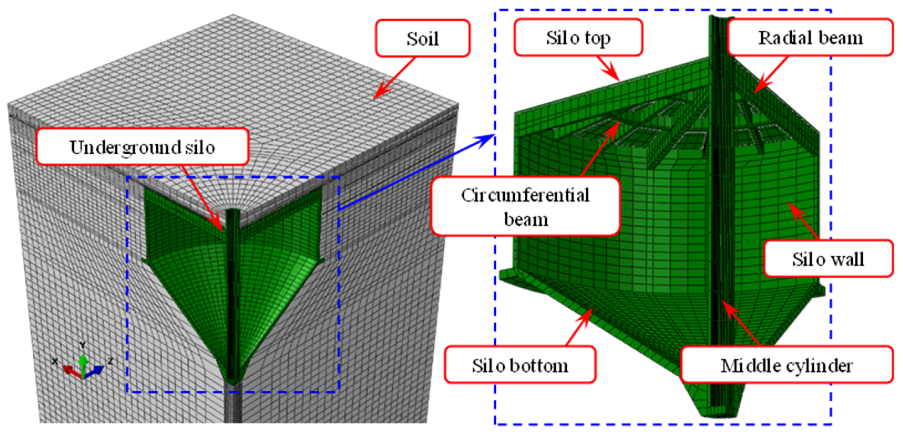
3.1. Construction of FE Model

The geometric parameters of the FE model for the underground RC grain silo are the same as the actual engineering (Section 2). The underground silo is mainly composed of components such as the silo wall, silo bottom, silo top, and middle cylinder without considering the drainage slope and the grain entrance of the silo top. An overall FE model that considers the interaction between the underground silo and soil was constructed based on the theory of soil–structure interaction. According to the boundary effect, the established soil model size is 70 m (long) × 70 m (width) × 60 m (depth), which is 3–4 times the size of the underground silo model. Because of the symmetry, a quarter model for the underground silo and soil was established to improve the calculation efficiency. The FE model of the underground silo and surrounding soil established in this research is shown in Figure 2.
The solid element C3D8R in ABAQUS was used to mesh the silo top, silo wall, silo bottom, middle cylinder, and surrounding soil. This element type is an 8-node solid element with reduced-integration stiffness, which can be used for nonlinear analysis such as contact, large deformation, plasticity, and failure. The overall mesh size of the underground silo and the surrounding soil was 0.5 m and 1 m, respectively, while the connection of each component adopted a refined mesh size to obtain more accurate results. Figure 2 depicts the FE meshes of the underground RC grain silo and the surrounding soil.

3.2. Material Properties

The Mohr–Coulomb plastic model was used to simulate the soil around the underground silo. The Mohr–Coulomb model is suitable for elastoplastic materials, including most rock and soil masses, and can better reflect the softening and hardening characteristics of soil. The yield criterion of the Mohr–Coulomb model can be expressed as
τ f = c + σ tan φ
where τf is the shear strength, c is the cohesion, σ is the normal stress, and φ is the internal friction angle of the soil. The envelope curve equation of the Mohr–Coulomb model can be expressed as
σ 1 σ 2 2 = σ 1 + σ 2 2 sin φ + c cos φ
F σ 1 σ 2 2 σ 1 + σ 2 2 sin φ c cos φ = 0
In the principal stress space, the failure surface of the soil can be described as
F σ 1 σ 2 2 2 c cos φ + σ 1 + σ 2 sin φ 2 · σ 2 σ 3 2 2 c cos φ + σ 2 + σ 3 sin φ 2 · σ 1 σ 1 2 2 c cos φ + σ 1 + σ 3 sin φ 2 = 0
Due to the overall compression state of the underground RC grain silo during backfilling construction, the concrete of the underground silo adopted the linear elastic constitutive relationship according to the Chinese design code GB50010-2010 [24], with an elastic modulus of E = 32,500 MPa, a Poisson ratio of μ = 0.2, and a concrete density of ρ = 2500 kg/m3.

3.3. Interaction and Boundary Conditions

The interaction modeling of components is essential for the accuracy of FE analysis. A surface-to-surface contact procedure was utilized between the underground RC grain silo and the surrounding soil. The normal behavior between the surface of the underground silo and the surrounding soil adopted “hard” contact, while the tangential behavior adopted the “penalty” friction formulation with a friction coefficient of 0.45. The embedding and overlapping phenomena in the normal direction were eliminated. When the contact pressure is 0, the contact surface splits and the set interaction is removed. In the interaction between the underground silo and the surrounding soil, the outer surface of the silo was set as the master surface, while the surface of the soil was defined as the slave surface. Since the concrete of each component of the underground silo is cast in place, tie constraints were applied between each component, and all the rotational degrees of freedom (DOFs) were constrained. Soil backfilling construction was achieved by changing the activation state of soil units. The soil backfilling construction was divided into 12 steps, and layered backfilling was carried out from the position of the bottom cross-section of the silo wall (−10.26 m). The first 10 steps backfilled 1 m each time, and the 11th and 12th steps backfilled 0.63 m each time until the thickness of the soil covering the silo top reached 1.5 m.
The boundary conditions are critical for FE analysis. Since the quarter model of the underground RC grain silo and the surrounding soil was established, the symmetric boundary condition (SBC) was applied to the surface at the symmetric plane of the FE model. The boundary conditions are shown in Figure 3. The x-axis SBC was applied to Surface 1, for which the Translational displacement U1 and the Rotational displacements R2 and R3 of all the nodes on Surface 1 were limited. Similarly, the z-axis SBC was applied to Surface 2, for which the Translational displacement U2 and the Rotational displacements R1 and R3 of all the nodes on Surface 2 were suppressed. All DOFs of the bottom surface of the soil were constrained.

4. Results and Discussion

4.1. Silo and Soil Settlement

Figure 4 depicts the vertical displacement contours of the underground RC grain silo and the surrounding soil after the completion of backfilling construction. As shown in Figure 4a, the underground silo suffers a total settlement of 0.021 m because of self-weight and the above soil load during the backfilling construction processes. The maximum vertical displacement of the silo is located at the mid-span cross-section of the radial primary beam at the silo top. The maximum displacement includes the overall settlement of the underground silo and the deflection of the silo top under the action of self-weight and above soil load. It can be observed from Figure 4b that backfilling construction will induce the settlement of the surrounding soil. After the completion of backfilling construction, the maximum vertical displacement of the soil around the silo is 0.036 m, which is located above the mid-span cross-section of the radial primary beam. Additionally, a relatively large settlement occurs at the bottom cross-section of the silo wall (−10.26 m), and the maximum vertical displacement of this section is 0.032 m.

4.2. Deformation Characteristic

During the backfilling construction process, the deformation of the underground silo bottom is small under the action of the foundation reaction. The underground silo wall is deformed radially under the action of backfill soil pressure, whereas the underground silo top has a larger deflection under the action of self-weight and the above soil load. Therefore, this research focuses on the radial displacement of the silo wall and the deflection of the radial primary beam at the silo top during the backfilling construction process.

4.2.1. Radial Displacement of Silo Wall

Figure 5 shows the radial displacement variation in the underground silo wall during the backfilling construction process. The variation in the radial displacement of the silo wall is complicated, and the radial displacement of the silo wall shows an overall trend of increasing and then decreasing from the top to the bottom of the silo wall. The effect on the radial displacement of the silo wall is greatest during the last two processes of backfilling construction, namely the soil backfilling construction above the silo top. The overall radial displacement of the silo wall is small, and the maximum radial displacement is smaller than 1 mm. This suggests that the silo wall of the cylindrical shell RC structure has reasonably high radial stiffness.
The largest radial displacement variation in the underground silo wall during the backfilling construction process is presented in Figure 6. During the backfilling construction process, the maximum radial displacement of the silo wall first decreases and then increases. This is because, during the backfilling construction of the soil on the side of the warehouse wall, the lateral pressure on the warehouse wall will reduce the radial displacement of the warehouse wall. However, during the backfilling construction of the soil on the upper part of the warehouse top, the soil will cause a large bending moment on the structure of the warehouse top beam and slab, and the warehouse top beam and slab will solidify with the warehouse wall. Therefore, the bending moment caused by the soil on the warehouse top will be transmitted to the warehouse wall, resulting in an increase in the displacement of the warehouse wall. The maximum radial displacement of the silo wall decreases from 0.39 mm to 0.09 mm during the soil backfilling construction around the silo wall but increases to 0.84 mm after the completion of soil backfilling construction above the silo top. The maximum radial displacement of the silo wall increases by 114.5% over the entire backfilling construction. The existing research indicates that the limit value of radial displacement of the grain silo wall is 12 mm [25]. Accordingly, the radial displacement of the underground silo wall is significantly smaller than the limit value.

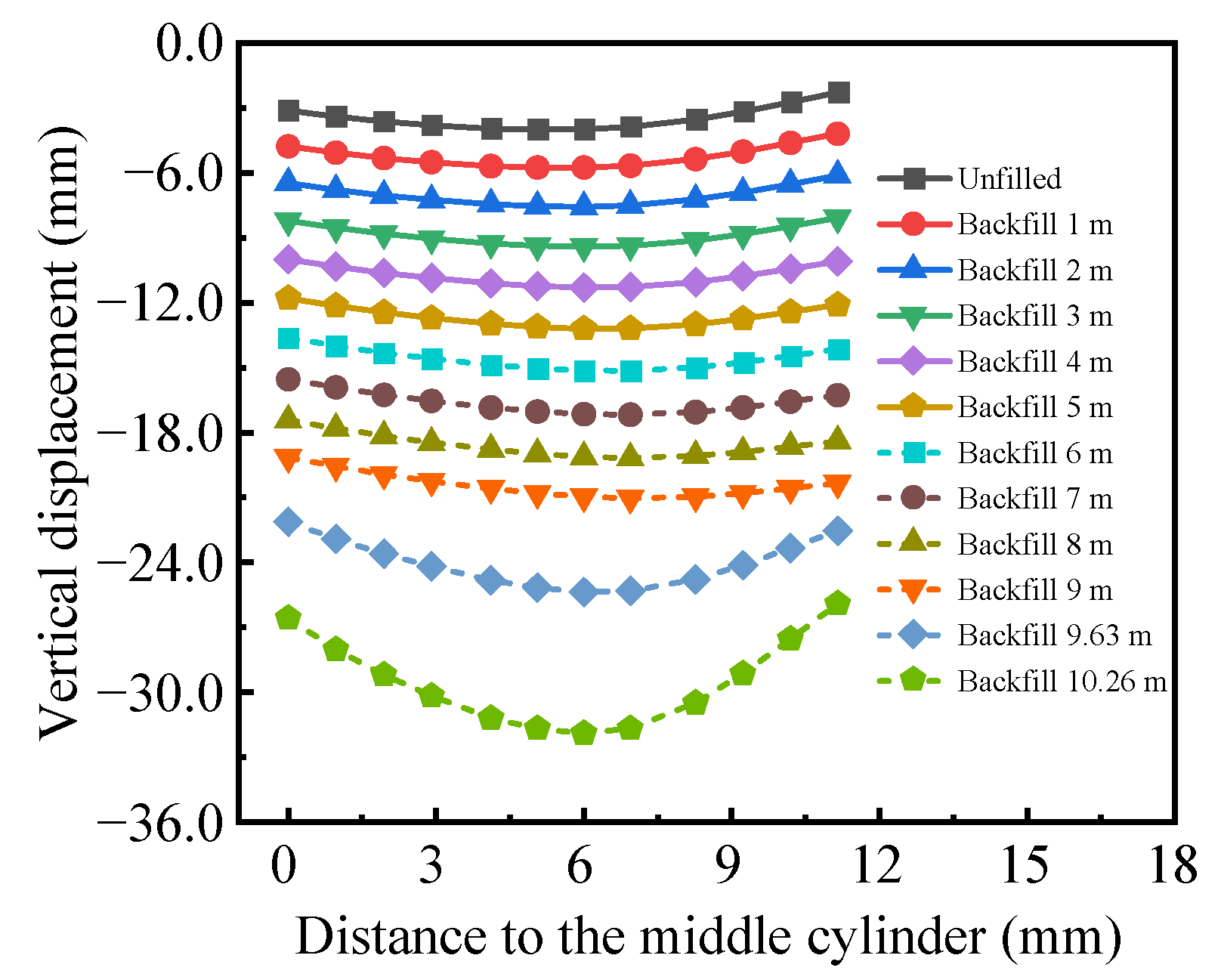
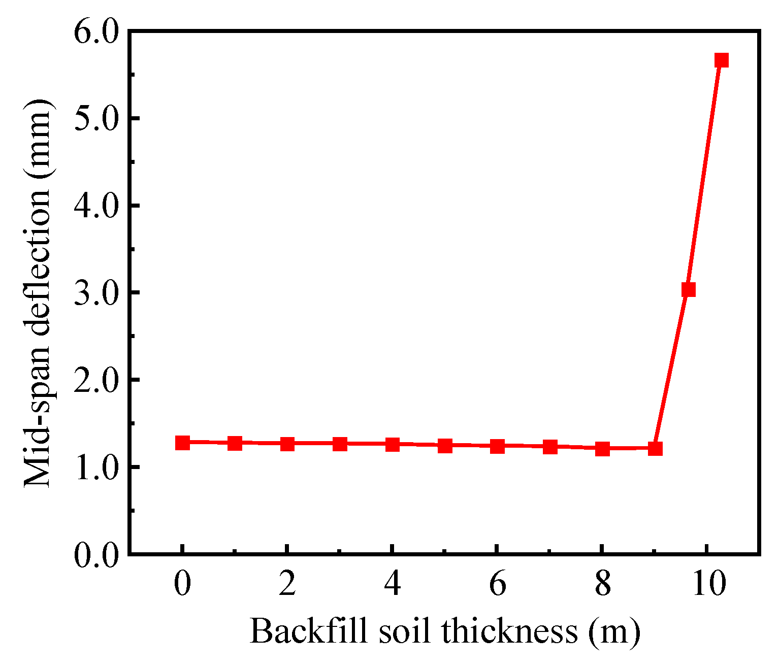
4.2.2. Vertical Displacement of Radial Primary Beam

Figure 7 plots the vertical displacement of the radial primary beam at the underground silo top during the backfilling construction process. The vertical displacement of all nodes of the radial primary beam increases as the thickness of the backfill soil increases. This is because the overall settlement of the underground silo increases as the soil back-filling progresses. Before the backfilling construction, the vertical displacements of the middle cylinder end, silo wall end, and mid-span cross-section of the radial primary beam are 3.11 mm, 2.28 mm, and 3.98 mm, respectively. When the backfill soil thickness reaches 9 m, these vertical displacements increase significantly to 19.15 mm, 20.33 mm, and 20.96 mm, respectively. After the completion of backfilling construction, these vertical displacements further increase to 26.57 mm, 25.90 mm, and 31.90 mm, respectively.
The mid-span deflection of the radial primary beam at the silo top during the backfilling construction process is shown in Figure 8. The mid-span deflection of the radial primary beam remains almost constant during the back-filling construction of the soil around the silo wall, whereas the mid-span deflection significantly increases during the last two steps of the backfilling construction. Before the backfilling construction, the mid-span deflection of the radial primary beam is 1.29 mm. When the backfill soil thickness reaches 9 m, the mid-span deflection of the radial primary beam is observed to be 1.22 mm. After the completion of backfilling construction, the mid-span deflection increases to 5.67 mm. Compared with before the backfilling construction, the mid-span deflection of the radial primary beam increases by 3.4 times after the completion of backfilling construction. This is because, before the backfilling of the soil above the silo top, the radial primary beam deflection is mainly caused by the self-weight. Nevertheless, after the completion of backfilling construction, the radial primary beam deflection is mainly caused by the combined action of the self-weight and the above soil load. According to the current design code, when the beam span L0 is greater than 9 m, the deflection limit value of the beam is L0/300. Hence, the deflection limit value is 39.2 mm for the radial primary beam, and the maximum deflection of the radial primary beam does not exceed the limit value, which fits the requirements of the current design code.

4.3. Stress Distribution

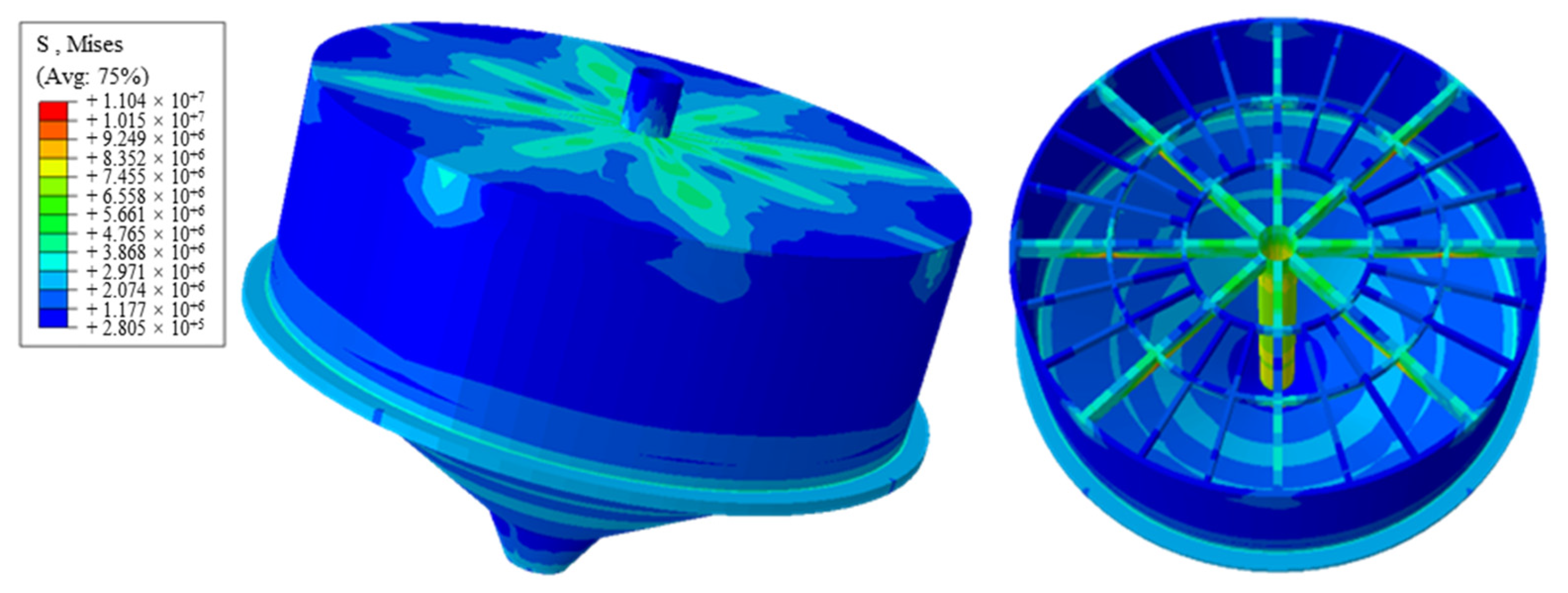
4.3.1. Von Mises Stress Distribution

Figure 9 displays the von Mises stress contours of the underground RC grain silo after the completion of backfilling construction. It can be observed that the overall mechanical performance of the underground silo is well. When the backfilling construction is completed, the von Mises stresses of the silo wall, silo top, and silo bottom are small, whereas stress concentration occurs at the connection of the silo wall and the radial primary beam, as well as the connection of the silo top and the radial primary beam. The maximum von Mises stress is located at the bottom of the mid-span cross-section of the radial primary beam, which is 11.04 MPa. This is because the bottom of the mid-span cross-section of the radial primary beam experiences high tensile stress under the action of self-weight and above soil load.
Figure 10 illustrates the variation in von Mises stresses in the underground silo during the backfilling construction process. From the results presented in Figure 10a, the von Mises stress on the silo wall decreases first and then increases from top to bottom. The stress at the connection between the silo wall and the radial primary beam is complex, which leads to stress concentration. The von Mises stress at the bottom of the silo wall is higher, and the von Mises stress of the silo wall decreases gradually from the bottom to 1 m away from the silo top. The von Mises stress at the bottom of the silo wall increases as the thickness of the backfill soil increases. It can be seen from Figure 10b that the maximal von Mises stress of the radial primary beam is relatively high. The von Mises stress reduces initially; then it increases before decreasing again as the distance from the middle cylinder increases along the length direction of the radial primary beam. The maximum von Mises stress is distributed at the radial primary beam bottom of the cross-section connected with the circumferential primary beam, which is about 7 m away from the middle cylinder. The backfilling construction of the soil around the silo wall has little effect on the von Mises stress of the radial primary beam. During the backfilling construction of the soil above the silo top, the von Mises stress of the radial primary beam increases significantly. As shown in Figure 10c, the von Mises stress distribution at the silo bottom is complicated, but the overall stress distribution of the inverted conical shell RC structure is even, without significant stress concentration. Before backfilling construction, the von Mises stress changes slightly along the sloping surface of the inverted conical shell. However, during the backfilling construction process, the von Mises stress gradually increases along the sloping surface of the inverted conical shell. The von Mises stress at each node along the sloping surface increases gradually with the increase in backfill soil thickness, and the von Mises stress of the silo bottom increases evenly with each soil backfilling step.

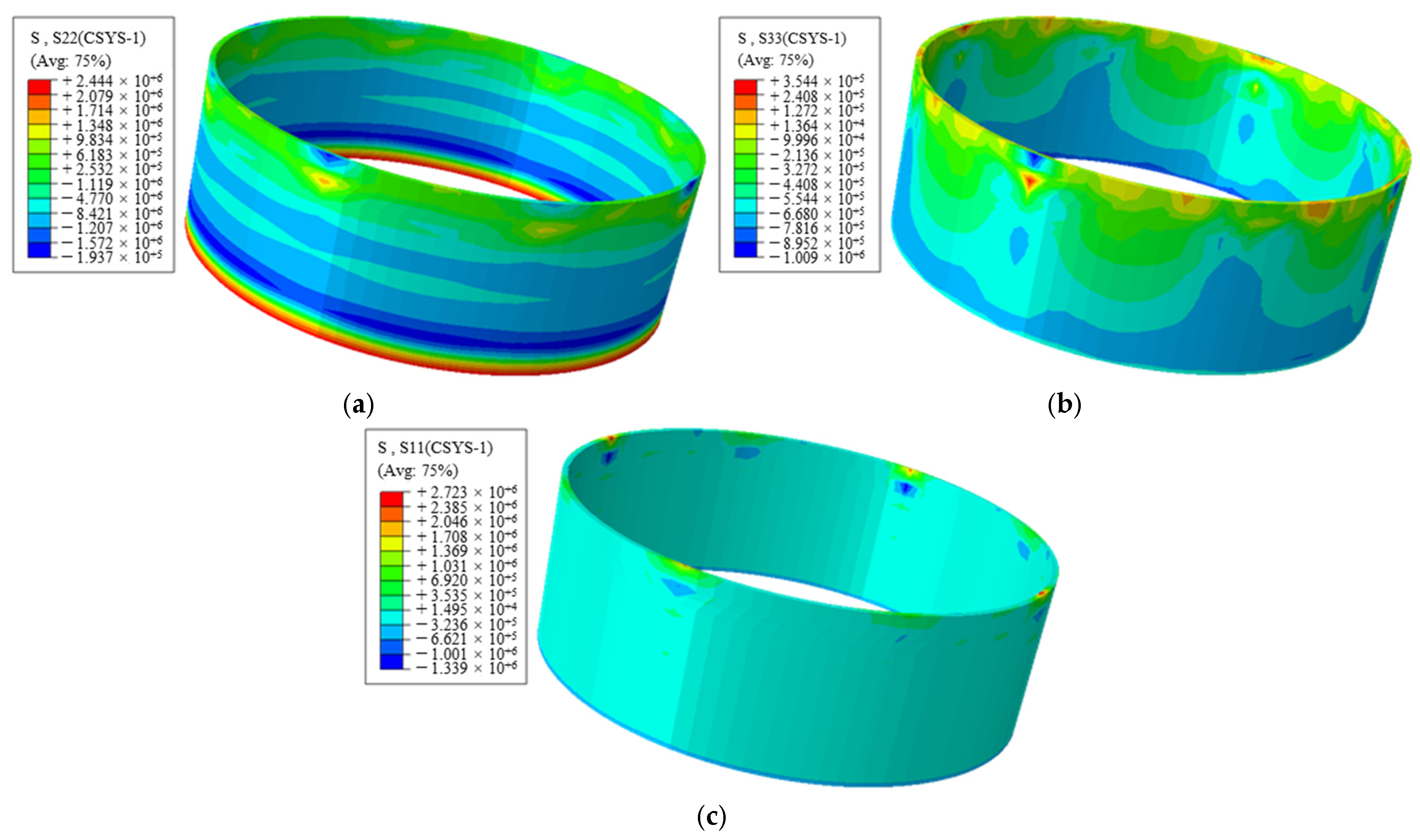
4.3.2. Normal Stress Distribution of Silo Wall

Figure 11 presents the circumferential, vertical, and radial normal stress distribution of the underground silo wall after the completion of backfilling construction. It can be observed from Figure 11 that stress concentration occurs at the connection between the radial primary beam and the silo wall. The maximum circumferential tensile stress of the silo wall is located at the bottom of the silo wall, which is 2.44 MPa. The maximum circumferential compressive stress of the silo wall, which reaches 1.94 MPa, is located at the connection between the radial primary beam and the silo wall. In addition, the circumferential tensile stress at this connection position is 1.79 MPa. A significant circumferential compressive stress also appeared at the cross-section 1.5 m away from the bottom of the silo wall, which is 1.91 MPa. The maximum vertical tensile and compressive stresses and the maximum radial tensile and compressive stresses of the silo wall are all located at the connection between the radial primary beam and the silo wall, which are 3.54 MPa, 1.01 MPa, 2.72 MPa, and 1.34 MPa, respectively. The standard values (95% confidence level) of tensile and compressive strength of C40 concrete are 2.39 MPa and 26.8 MPa, respectively [24]. Consequently, there is a high risk of concrete cracking at the bottom of the silo wall and the connection between the radial primary beam and the silo wall. As the compressive stress of the concrete on the silo wall is significantly smaller than the compressive strength, the risk of compressive failure of the concrete on the silo wall is minimal.

4.3.3. Normal Stress Distribution of Silo Top

Figure 12 presents the radial and circumferential normal stress distribution of the underground silo top after the completion of backfilling construction. As illustrated in Figure 12, the maximum radial tensile stress of the silo top is located at the radial primary beam bottom of the cross-section connected with the circumferential primary beam, which is 9.57 MPa. The maximum circumferential tensile stress of the silo top, which reaches 5.06 MPa, is located at the mid-span cross-section of the circumferential primary beam. The connection between the silo top slab and the middle cylinder also encountered high circumferential tensile stress, which reached 4.66 MPa. Meanwhile, the maximum radial and circumferential compressive stresses of the silo top are both located at the middle cylinder end of the radial primary beam, which are 6.48 MPa and 7.74 MPa. The maximum tensile stress of the radial and circumferential primary beam at the silo top exceeds the tensile strength of C40 concrete. Therefore, the concrete at the bottom of the primary beam and the connection between the silo top slab and the middle cylinder has cracked, and these concrete components are in service with cracks. Given that the compressive stress of the concrete on the silo top is considerably lower than the compressive strength, the concrete on the silo top will not undergo compressive failure.

5. Conclusions

The current research developed a numerical simulation method to investigate the mechanical properties of underground silos during backfilling construction processes. A three-dimensional FE model for the underground RC grain silo and the surrounding soil was established using ABAQUS2022, taking into consideration the nonlinear contact between the underground silo and the soil and the material nonlinear behavior of the soil. The deformation characteristics and stress distribution of the underground silo during the backfilling construction process were revealed. The conclusions derived from this research are summarized as follows:
(1) During the backfilling construction process, the underground RC grain silo suffers a total settlement of 21 mm because of self-weight and the above soil load. Backfilling construction will induce settlement of the surrounding soil. After the completion of backfilling construction, the maximum vertical displacement of the soil around the silo is 36 mm, which is located above the mid-span cross-section of the radial primary beam.
(2) During the backfilling construction process, the maximum radial displacement of the silo wall first decreases and then increases. The radial displacement of the underground silo wall is significantly smaller than the limit value. The maximum radial displacement of the silo wall increases to 0.84 mm after the completion of soil backfilling construction. The maximum radial displacement of the silo wall increases by 114.5% over the entire backfilling construction.
(3) The mid-span deflection of the radial primary beam remains almost constant during the backfilling of the soil around the silo wall, whereas the mid-span deflection significantly increases during the last two steps of the back-filling construction. The maximum deflection of the radial primary beam does not exceed the limit value, which fits the requirements of the current design code. The mid-span deflection of the radial primary beam is 1.29 mm and 5.67 mm before and after backfilling construction, which increases by 3.4 times.
(4) After the completion of backfilling construction, stress concentration occurs at the connection of the silo wall and the radial primary beam. The maximum circumferential tensile stress of the silo wall is located at the bottom of the wall, while the maximum vertical tensile stress is situated at the connection between the radial primary beam and the silo wall. There is a high risk of concrete cracking at the bottom of the silo wall and the connection between the radial primary beam and the silo wall.
(5) After the completion of backfilling construction, the maximum radial tensile stress of the silo top is located at the radial primary beam bottom of the cross-section connected with the circumferential primary beam, while the maximum circumferential tensile stress is located at the mid-span cross-section of the circumferential primary beam. The concrete at the bottom of the primary beam and the connection between the silo top slab and the middle cylinder has cracked.
Overall, this paper presents a detailed numerical study of the mechanical properties of underground RC grain silos during backfilling construction processes. The research results can provide important support for the design and evaluation of underground RC grain silos. Since there is still a lack of relevant experimental data, we will use a combination of indoor experiments and on-site monitoring to test the mechanical properties of underground silos in future research. The influence of different parameters such as silo wall thickness, silo bottom thickness, concrete strength grade, and silo top beam and slab size on the mechanical properties of underground silos will be the focus of future research.

Author Contributions

Conceptualization, G.C. and L.Y.; Methodology, L.Y.; Software, L.Y.; Validation, C.C. and C.L.; Formal Analysis, B.Z. and C.L.; Investigation, C.C.; Resources, G.C.; Data Curation, L.Y.; Writing—Original Draft Preparation, L.Y.; Writing—Review and Editing, G.C. and B.Z.; Visualization, B.Z.; Project Administration, G.C. and C.L.; Funding Acquisition, G.C. All authors have read and agreed to the published version of the manuscript.

Funding

This research was funded by the National Grain Public Welfare Research Project of China (Grant No. 201513001-01), the Key Research and Development Project of Henan Province (Grant No. 241111322600), the Science and Technology Research Project of Henan Province (Grant No. 242102241012), the High Level Talents Fund Project of Henan University of Technology (Grant No. 2023BS060), and the Open Project of Henan Key Laboratory of Grain and Oil Storage Facility & Safety (Grant No. 2024KF07).

Data Availability Statement

All data generated or analyzed during this study are included in this article.

Conflicts of Interest

The authors declare that they have no financial and personal relationships with other people or organizations that can inappropriately influence the work; there is no professional or other personal interest of any nature or kind in any product, service, and/or company that could be construed as influencing the position presented in or the review of the manuscript.

References

  1. Chen, G.; Hou, J.; Liu, C. A Scientometric Review of Grain Storage Technology in the Past 15 Years (2007–2022) Based on Knowledge Graph and Visualization. Foods 2022, 11, 3836. [Google Scholar] [CrossRef]
  2. Liu, C.; Chen, G.; Zhou, Y.; Zheng, D.; Zhang, Z. Element tests and simulation of effects of vertical pressure on compression and mildew of wheat. Comput. Electron. Agric. 2022, 203, 107447. [Google Scholar] [CrossRef]
  3. Cui, H.; Zhang, Q.; Wu, W.; Zhang, H.; Ji, J.; Ma, H. Modeling and Application of Temporal Correlation of Grain Temperature during Grain Storage. Agriculture 2022, 12, 1883. [Google Scholar] [CrossRef]
  4. Zevgolis, I.E.; Mavrikos, A.A.; Kaliampakos, D.C. Construction, storage capacity and economics of an underground warehousing—Logistics center in Athens, Greece. Tunn. Undergr. Space Technol. 2004, 19, 165–173. [Google Scholar] [CrossRef]
  5. Valls, A.; Garcia, F.; Ramirez, M.; Benlloch, J. Understanding subterranean grain storage heritage in the Mediterranean region: The Valencian silos (Spain). Tunn. Undergr. Space Technol. 2015, 50, 178–188. [Google Scholar] [CrossRef]
  6. Yu, H.; Wang, L.; Wang, Z.; Zheng, P. Present condition and outlook for underground silos. J. Henan Univ. Technol. Nat. Sci. Ed. 2008, 29, 79–81. [Google Scholar] [CrossRef]
  7. Wang, Z.; Chuai, J.; Liu, Y.; Wang, L. Current Situation and New Progresses of Structure Design of Underground Silos. J. Henan Univ. Technol. Nat. Sci. Ed. 2019, 40, 132–138. [Google Scholar] [CrossRef]
  8. Pan, Y.; Fang, H.; Li, B.; Wang, F. Stability analysis and full-scale test of a new recyclable supporting structure for underground ecological granaries. Eng. Struct. 2019, 192, 205–219. [Google Scholar] [CrossRef]
  9. Chen, G.; Cui, C.; Fu, Z.; Jin, L. Monitoring analysis on the stress of reinforced concrete underground grain silo. J. Henan Univ. Technol. Nat. Sci. Ed. 2016, 37, 90–95. [Google Scholar] [CrossRef]
  10. GB50077-2017; Standard for Design of Reinforced Concrete Silos. China Planning Press: Beijing, China, 2015.
  11. Chen, G.; Yue, L.; Wang, Z.; Wang, H.; Zhang, H. Quasistatic Temperature Field Simulation of Reinforced Concrete Underground Warehouse Grain. J. Chin. Cereals Oils Assoc. 2014, 29, 79–83. [Google Scholar]
  12. Xiong, X.; Jin, L.; Shi, X.; Guo, H. Study on wall bearing capacity calculation method of reinforced concrete underground granary. J. Henan Univ. Technol. Nat. Sci. Ed. 2015, 36, 95–99. [Google Scholar] [CrossRef]
  13. Xiong, X.; Jin, L.; Wang, Z. Earth pressure and bearing capacity analysis on the wall of reinforced concrete underground granary. J. Basic Sci. Eng. 2016, 24, 103–114. [Google Scholar] [CrossRef]
  14. Chen, G.; Cui, C.; Fu, Z.; Jiang, M. Reliability sensitivity analysis of underground silo based on Monte-Carlo stochastic finite element method. J. Henan Univ. Technol. Nat. Sci. Ed. 2017, 38, 86–90+95. [Google Scholar] [CrossRef]
  15. Liu, H.; Meng, W.; Wang, Z.; Tian, D.; Xu, X.; Liu, X. Buoyancy early warning of underground granary with “2:8 lime soil” backfilling. Trans. Chin. Soc. Agric. Eng. 2019, 35, 299–305. [Google Scholar] [CrossRef]
  16. Liu, H.; Xu, X.; Zhang, H.; Wang, Z.; Yang, J.; Ma, T. Friction Analysis of Underground Silos during Backfilling. Mod. Food Sci. Technol. 2021, 37, 175–183. [Google Scholar] [CrossRef]
  17. Chen, G.; Cui, C.; Fu, Z.; Jiang, M. Research on Deformation and Internal Force of Reinforced Concrete Underground Grain Silo Wall. Chin. J. Undergr. Space Eng. 2019, 15, 458–464. [Google Scholar]
  18. Jin, L.; Liang, X.; Huo, C.; Wang, Z.; Wang, Z. Engineering test and numerical analysis of underground concrete silo. J. Civ. Environ. Eng. 2020, 42, 40–45. [Google Scholar] [CrossRef]
  19. Chuai, J.; Hou, Z.; Wang, Z.; Wang, L.; Jin, J. Mechanical Properties of the Vertical Joints of Prefabricated Underground Silo Steel Plate Concrete Wall. Adv. Civ. Eng. 2020, 2020, 6643811. [Google Scholar] [CrossRef]
  20. Zhang, H.; Han, K.; Yang, J.; Chen, L. Experimental and Numerical Investigation of Plastic-Concrete Waterproof Walls of an Underground Granary Subject to Combined Bending Moment and Water Pressure. Buildings 2022, 12, 893. [Google Scholar] [CrossRef]
  21. Zhang, H.; Pan, C.; Yang, J.; Xi, H. A hydrostatic test study on the waterproofing of an underground ecological granary using a plastic-concrete system. Structures 2022, 44, 58–71. [Google Scholar] [CrossRef]
  22. Zhang, H.; Wang, H.; Zhou, Y.; Chang, Z. Waterproofing performance of polypropylene-concrete wall of underground silo under combined compressive stress and water pressure. Heliyon 2022, 8, e12074. [Google Scholar] [CrossRef] [PubMed]
  23. Zhou, L.; Zhu, Z.; Liu, B.; Fan, Y. The effect of radial cracks on tunnel stability. Geomech. Eng. 2018, 15, 721–728. [Google Scholar]
  24. GB50010-2010; Code for Design of Concrete Structures. China Architecture & Building Press: Beijing, China, 2015.
  25. Li, G.; Xu, L.; Cheng, G. Reliability analysis for complex large-scale structures based on ANSYS software. Build. Struct. 2002, 5, 58–61. [Google Scholar] [CrossRef]
Figure 1. Underground RC grain silo: (a) general view; (b) front view.
Buildings 14 03907 g001
Figure 2. FE model of underground RC grain silo and surrounding soil.
Buildings 14 03907 g002
Figure 3. Boundary conditions of FE model.
Buildings 14 03907 g003
Figure 4. Vertical displacement contours of underground RC grain silo and surrounding soil: (a) underground silo; (b) surrounding soil.
Buildings 14 03907 g004
Figure 5. Radial displacement of underground silo wall during backfilling construction.
Buildings 14 03907 g005
Figure 6. Maximum radial displacement of underground silo wall during backfilling construction.
Buildings 14 03907 g006
Figure 7. Vertical displacement of radial primary beam of underground silo during backfilling construction.
Buildings 14 03907 g007
Figure 8. Mid-span deflection of radial primary beam of the underground silo during backfilling construction.
Buildings 14 03907 g008
Figure 9. von Mises stress contours of underground RC grain silo.
Buildings 14 03907 g009
Figure 10. von Mises stress of underground RC grain silo during backfilling construction: (a) silo wall; (b) radial primary beam; (c) silo bottom.
Buildings 14 03907 g010
Figure 11. Normal stress contours of underground silo wall: (a) circumferential normal stress; (b) vertical normal stress; (c) radial normal stress.
Buildings 14 03907 g011
Figure 12. Normal stress contours of underground silo top: (a) radial normal stress; (b) circumferential normal stress.
Buildings 14 03907 g012
Table 1. Physical and mechanical properties of each soil layer.
Soil LayerSoil TypeAverage
Thickness (m)
Accumulated
Depth (m)
Moisture
Content (%)
Specific
Gravity (kN/m3)
Void RatioInternal Friction
Angle (°)
1Silty sand1.231.2321.4200.54028
2Silty clay1.762.9922.620.40.83513.3
3Silt1.854.8422.120.80.68224.1
4Silty sand5.5610.4021.4200.54028
5Silt1.3011.7024.421.30.68825.5
6Silty sand6.5818.2821.4200.54028
7Silt1.2919.5723.720.60.67826
8Silty sand6.8826.4521.4200.54028
Disclaimer/Publisher’s Note: The statements, opinions and data contained in all publications are solely those of the individual author(s) and contributor(s) and not of MDPI and/or the editor(s). MDPI and/or the editor(s) disclaim responsibility for any injury to people or property resulting from any ideas, methods, instructions or products referred to in the content.

