Article

Accurate Dynamic Analysis Method of Cable-Damper System Based on Dynamic Stiffness Method

1
Investment Company of China Railway Seventh Group Co., Ltd., Zhengzhou 450016, China
2
School of Civil Engineering, Zhengzhou University, Zhengzhou 450001, China
3
School of Water Conservancy and Transportation, Zhengzhou University, Zhengzhou 450001, China
4
School of Civil Engineering, Southeast University, Nanjing 211189, China
*
Author to whom correspondence should be addressed.
Buildings 2024, 14(12), 4007; https://doi.org/10.3390/buildings14124007
Submission received: 30 October 2024 / Revised: 28 November 2024 / Accepted: 15 December 2024 / Published: 17 December 2024
(This article belongs to the Special Issue Advances and Applications in Structural Vibration Control)

Abstract

:
To suppress large vibrations of the cable in cable-stayed bridges, it is common to install transverse dampers near the end of the cable. This paper focuses on the cable-damper system; based on the dynamic stiffness method, an accurate dynamic analysis method considering cable parameters, damper parameters, and cable forces is proposed. First, a mechanical analysis model is established which is closer to the cable with a transverse damper installed in the bridge. The model considers the cable bending stiffness, sag, inclination angle, cable force, damper stiffness, damping coefficient, and damper installation height. Then, the characteristic frequency equation of the cable-damper system is established, and a solution method that combines the initial value method and Newton–Raphson method is proposed. This method is confirmed to provide more accurate frequency analysis for the cable-damper system. Finally, using this method, the effect of the damper parameters on the dynamic characteristics of the system is investigated.

1. Introduction

Cable-stayed bridges are a cornerstone of modern civil engineering, widely celebrated for their ability to span vast distances with both structural efficiency and aesthetic appeal. These bridges are increasingly favored for their versatility in accommodating various load demands, as well as their ability to integrate into complex urban infrastructure. With the increase in cable length, their vibration problem under the excitation of environmental and traffic loads becomes more and more prominent [1,2]. To restrain large vibrations of the cable, installing transverse dampers near the anchor position of the cable near the main beam has become a very common measure to restrain the vibration [3,4]. The cable-damper system not only enhances the vibration response of individual cables, but also provides supplementary damping for the entire bridge [5]. This makes the cable system complicated and leads to inaccuracy when analyzing the dynamic characteristics of the cable using pure cable theory. Therefore, it is very important to analyze the system composed of cable and transverse damper as a whole to accurately analyze the dynamic characteristics of the cable and maintenance of a cable-supported bridge. In this paper, a cable with a transverse damper is called a cable-damper system.
At present, the research on the cable-damper system focuses on the optimization of the damper. Therefore, in the modeling of a cable-damper system, the cable is often simplified to a tensioned string model [6,7]. Neglecting sag and bending stiffness in existing models leads to inaccurate dynamic predictions, underestimating vibration amplitudes and damping effects [8]. Generally speaking, the sag and bending stiffness of the cable in a cable-stayed bridge are relatively small, but even a small sag will have a significant negative impact on the performance of the linear damper [9,10]. Sun et al. [11] incorporated the effects of cable sag and stiffness, enhancing the cable-reduced order model by including a viscous damper. The modified model employs one or two viscous dampers with varying nonlinearities to numerically analyze the cable’s behavior under different sag extensibility parameters. Mehrabi et al. [12] proposed a motion formula for a cable-damper system using finite difference methods, incorporating the effects of cable bending stiffness, sag, variable cross-section, and boundary conditions. The accuracy and computational cost of this finite difference (FD) model are strongly influenced by spatial and temporal discretization. However, that study is limited to the first vibration mode of the cable. Fujino and Hoang [13] developed a free vibration analysis model for an inclined uniform cable with transverse dampers, which considered the influences of cable bending stiffness, sag, and damper support, each of which was reflected by the corresponding reduction factor. Pacheco et al. [6] proposed a straightforward design methodology for external viscous dampers in cable systems, utilizing a general estimation curve. This approach integrates the cable’s modal damping ratio with key parameters such as length, mass per unit length, and fundamental frequency, alongside factors like additional dampers, their size, and placement. Javanbakht [14] proposed a control-oriented numerical model for evaluating the dynamic response of a stay cable equipped with a damper/actuator, proposed based on the mode superposition method (MSM) with enhanced shape functions. This enhancement accounts for the effect of the truncated higher modes by introducing a static correction term. Zhou et al. [15] performed a stochastic analysis of the coupled in-plane and out-of-plane vibrations in the cable-damper system. By selecting the static deflection shape at the damper location and the first sine term as shape functions, they derived a reduced four-degree-of-freedom system of nonlinear stochastic ordinary differential equations to characterize the cable’s dynamic response. These two methods primarily address the dynamic force response of the cable.
In the research mentioned above, the damper and cable are simplified to varying extents, and the system description lacks sufficient comprehensiveness. Unlike the cable-damper systems used in practical engineering, the accuracy of the cable modal parameters obtained through this method is also limited. Furthermore, existing approaches that employ reduction factors or fitting techniques to account for the damper’s effect fail to distinguish between the impacts of the cable and damper parameters. As a result, these methods are unsuitable for solving inverse problems with high accuracy, especially for cables in service. Therefore, it is essential to develop a high-precision analytical frequency characteristic equation that can be applied to both forward and inverse analyses of the cable-damper system. The dynamic stiffness method (DSM) is an efficient and accurate dynamic analysis method that can solve the problems of accuracy and consideration of all relevant design parameters in the dynamic response [16,17].
In this paper, an accurate dynamic analysis method of the cable-damper system is proposed based on the dynamic stiffness theory with minimal simplification of the cable. In this method, the cable force, sag, bending stiffness, inclination angle, and mass per unit length of the cable are considered, and the damper stiffness, damping coefficient, and damper position, to more accurately represent the real-world behavior of the cable system. In the second part, the dynamic analysis theory of the cable-damper system is established based on the dynamic stiffness theory, and the analytic frequency characteristic equation of the system is presented. In the third part, by studying the characteristics of the frequency characteristic function, a numerical method for solving the frequency characteristic equation is proposed. In the fourth part, the accuracy of the proposed frequency equation is verified by the cable experiments in the literature and the real cable monitoring of Shaozhou Bridge. In the fifth part, the influence of damper parameters on the dynamic characteristics of the cable is analyzed. The conclusion of this paper is given in the sixth part.

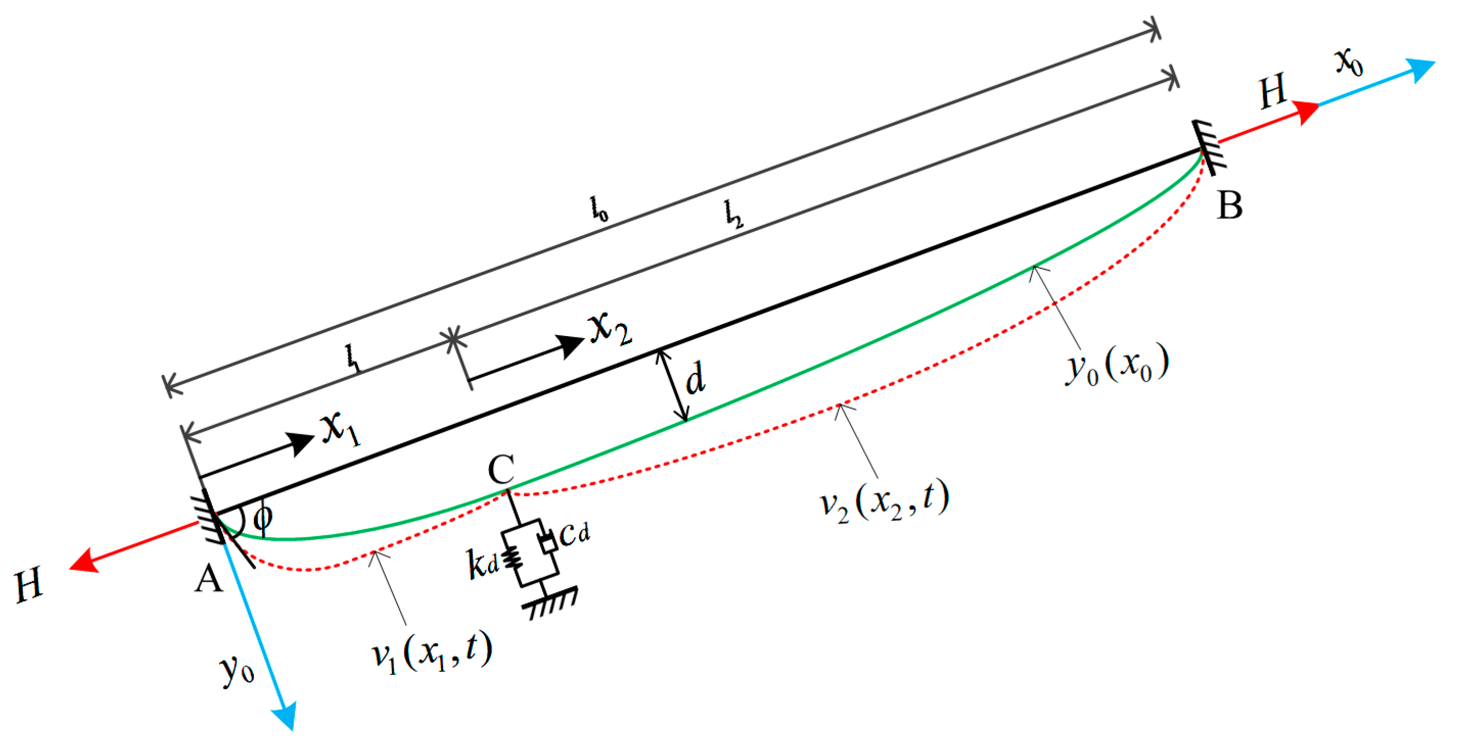
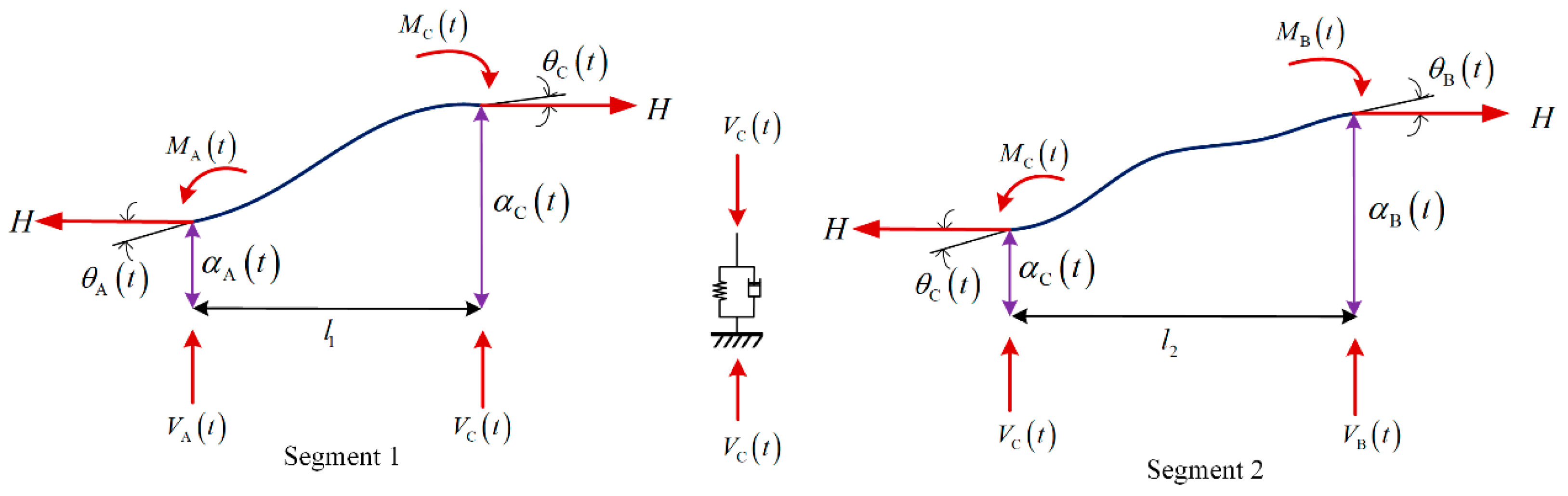
2. Dynamic Analysis Theory of Cable-Damper System

For cables installed with transverse dampers in a cable-stayed bridge, the mechanical model can be simplified as in Figure 1. The model considers the cable force, sag, bending stiffness, inclination angle boundary condition, and mass per unit length, along with the damper stiffness, damping coefficient, and position, providing a more accurate representation of the actual cable system. In the model, the transverse damper is approximated as a linear damper, represented by the combination of a linear spring and a viscous damping element [18]. In Figure 1, the stiffness of the linear spring is k d , and the damping coefficient of the viscous damper is c d . Under static action, the transverse damper has no impact on the cable. y x 0 represents the static configuration of the cable, accounting for sag, angle, and cable force. For shallow cables, this configuration can be approximated as a quadratic parabola. When the cable vibrates, the external damper will affect the dynamic configuration of the cable, as shown in v x j , t . When analyzing the cable-damper system in Figure 1, the cable is divided into two cable segments at the position C of the damper, and coordinate systems x j , y j are established for the original cable and the two cable segments. j = 0 indicates the original cable AB with l 0 length; j = 1 indicates the lower cable segment AC with l 1 length; j = 2 indicates the upper cable segment CB with l 2 length. θ is the angle between the cable and the horizontal plane, and d is the sag of the cable in the middle span. The cable force H is the average cable force, regardless of the change along its length.
In the dynamic analysis of the cable segment, the effects of internal damping and shear force are neglected. Using Hamilton’s principle, the control differential equation for in-plane vibration under free vibration is derived, accounting for the bending stiffness and sag of the cable segment.
E I 4 v ( x j , t ) x j 4 H 2 v ( x j , t ) x j 2 h j t d 2 y ( x 0 ) d x 0 2 + m 2 v ( x j , t ) t 2 = 0
where E I is the bending stiffness of the cable; m is the cable mass; h j t is the vibration-induced additional cable force [19]; and t is the time.
For Equation (1), by separating variables, we assume the solution takes the form of
v ( x j , t ) = φ ( x j ) e i ω d t
where φ ( x j ) is the displacement function of the cable segment; i = 1 , ω d is the natural circular frequency of the cable-damper system.
Substitute Equation (2) into Equation (1), and let ξ j = x j / l 0 ; the dimensionless cable vibration equation is
φ ^ I V ξ j γ 2 φ ^ ξ j ω ˜ 2 φ ^ ξ j = h ^ j
where φ ^ ξ j = φ x j E I / m g l 0 4 , γ 2 = H l 0 2 / E I , ω ˜ = ω d l 0 2 / E I / m , h ^ j = h j t cos θ / H e i ω d t .
The general solution of Equation (3) is
φ ^ ξ j = Φ ξ j + η j ω ˜ 2 η j 0 1 Φ ξ j d ξ j A 1 j A 2 j A 3 j A 4 j T
where Φ ξ j = e p ξ j e p ( 1 ξ j ) cos ( q ξ j ) sin ( q ξ j ) , p q = γ 4 4 + ω ˜ 2 ± γ 2 2 , η j = 64 A l 0 d 2 I l j s , l j s = 0 l j d s d x j 3 d x j is the effective length of the cable; A 1 j ~ A 4 j are the undetermined parameters.
In order to determine the undetermined parameters in Equation (4), the cable dynamic displacement boundary conditions and force edge boundary conditions as shown in Figure 2 are introduced.
Similarly, the dynamic displacement and internal force of the cable in the time domain are expressed by separating variables. Using the dimensionless method described earlier, it follows that the force and dynamic displacement boundary conditions for each cable segment satisfy the following relationship.
V * t = V ˜ * e i ω d t = m g l 0 φ ^ ξ j γ 2 φ ^ ξ j e i ω d t M * t = M ˜ * e i ω d t = m g l 0 2 φ ^ ξ j e i ω d t α * t = α ˜ * e i ω d t = m g l 0 4 E I φ ^ ξ j e i ω d t θ * t = θ ˜ * e i ω d t = m g l 0 3 E I φ ^ ξ j e i ω d t
where M ˜ * , V ˜ * , α ˜ * , θ ˜ * represent the bending moment amplitude, shear amplitude, lateral dynamic displacement amplitude, and angular dynamic displacement amplitude at nodes * ; * represents nodes A, B, and C in the cable segment.
By substituting Equation (4) into Equation (5), the dynamic equilibrium equation for the cable section is obtained as follows.
V ˜ A M ˜ A / l 0 V ˜ C M ˜ C / l 0 T = K 1 α ˜ A θ ˜ A l 0 α ˜ C θ ˜ C l 0 T V ˜ C M ˜ C / l 0 V ˜ B M ˜ B / l 0 T = K 2 α ˜ C θ ˜ C l 0 α ˜ B θ ˜ B l 0 T
where K j is the dynamic stiffness matrix of the cable segment, which is a function of frequency, force, and cable parameters. Its expression is shown in Equation (7).
K j = E I l 0 3 Φ ξ j | = 0 γ 2 Φ ξ j | = 0 Φ ξ j | = 0 Φ ξ j | = μ j + γ 2 Φ ξ j | = μ j Φ ξ j | = μ j Φ ξ j | = 0 Φ ξ j | = 0 Φ ξ j | = μ j Φ ξ j | = μ j + 1 0 1 0 η j ω ˜ 2 η j 0 1 Φ ξ j d ξ j 1
where μ j = l j / l 0 represents the installation position of the damper.
In engineering application, the damper is usually installed on the long cable and perpendicular to the cable. For the medium and long cable, the boundary conditions have little effect on its dynamic characteristics, and both ends of the cable are assumed to be fixed. In the analysis, it is assumed that the damper only provides transverse force and ignores the bending moment. Based on the above assumptions, the dynamic displacement amplitude vector and dynamic amplitude vector of the cable can be expressed as Equation (8).
α ˜ A θ ˜ A α ˜ C θ ˜ C α ˜ B θ ˜ B = 0 0 α ˜ C θ ˜ C 0 0 V ˜ A M ˜ A V ˜ C M ˜ C V ˜ B M ˜ B = 0 0 V ˜ C 0 0 0
For a general cable external damper, the mechanical model can be simplified to a linear spring and a linear viscous damper, whose transverse force amplitude in the frequency domain can be expressed as follows.
V ˜ C = k c α ˜ C = k d + i c d ω d α ˜ C
According to the assembly method of the stiffness matrix of finite element method, grouping Equation (6), and introducing the boundary conditions of Equations (9) and (10), the mechanical equilibrium equation of the cable which provides the transverse force damper can be obtained as follows.
k 33 1 + k 11 2 + k c k 34 1 + k 12 2 k 43 1 + k 21 2 k 44 1 + k 22 2 α ˜ C θ ˜ C l 0 = 0 0
where k n 1 n 2 j represents the element corresponding to the n 1 th row and the n 2 th column in the dynamic stiffness matrix K j of cable segment j , that is, the stiffness component corresponding to the lateral displacement and angular displacement at the installation position C of the damper. In particular, the dynamic stiffness matrix of the cable-damper system is defined as
K = k 33 1 + k 11 2 + k c k 34 1 + k 12 2 k 43 1 + k 21 2 k 44 1 + k 22 2
According to Equation (11) for a cable-damper system with vibration, the condition that the equation has a trivial solution is that the value of the determinant of the dynamic stiffness matrix is 0. Therefore, the frequency characteristic equation of the cable-damper system can be defined as
K = 0
In Equation (12), the dynamic stiffness matrix K of the cable-damper system is a function of the cable frequency, cable force, cable parameters, and damper parameters. Once the cable force, cable parameters, and damper parameters are known, the system’s frequency can be determined by solving Equation (12), enabling the analysis of its dynamic characteristics. Since Equation (12) is a complex transcendental equation, an analytical solution for the frequency cannot be directly obtained and must be solved numerically.

3. Solution of the Frequency Characteristic Equation for the Cable-Damper System

When considering the damper effect, K is a complex number, that is,
K = Re K + Im K i
For Equation (13) to be true, both Re K and Im K in Equation (14) must be 0. Considering the sparse characteristic of the cable frequency, this paper defines the characteristic frequency function of the cable-damper system as
F f H , P cable , P damper = 1 Re K + Im K
where f = ω d 2 π , P cable = l 0 , m , E I , D , P damper = k d , c d , μ 1 .
Thus, the problem of determining the frequency of the cable-damper system is transformed into finding the maximum value of Equation (14). The parameters of the cable-damper system in Table 1, which correspond to an actual existing cable, are used to analyze the characteristics of the frequency function of the system. During the analysis, for C1, the variation range of frequency f is 0.01 Hz–20 Hz; for C2, the variation range of frequency f is 0.01 Hz–10 Hz, and the frequency change intervals are all 0.01 Hz. The variation curve of the characteristic frequency function with frequency is obtained by Equation (14), as shown in Figure 3.
As shown in Figure 3, the characteristic frequency function of the cable-damper system exhibits multiple peaks as the frequency varies. The frequencies at these peaks correspond to the potential resonant frequencies of the system. To obtain a high precision cable frequency from the function image usually requires a lot of computation and human intervention. The numerical method can usually determine the solution of the equation according to the set calculation accuracy, but, for the functions with multiple peaks as shown in Figure 3, there is a case of missing roots. To accurately obtain the system frequencies of all orders, this paper proposes a two-step calculation method, tailored to the characteristics of the frequency function. First, the characteristic frequency function image is drawn through large frequency changes, and the interval where the frequency is located is preliminarily determined. Then, the Newton–Raphson Method is applied in each interval to obtain the frequency of cable-damper system that meets the accuracy requirements [20].

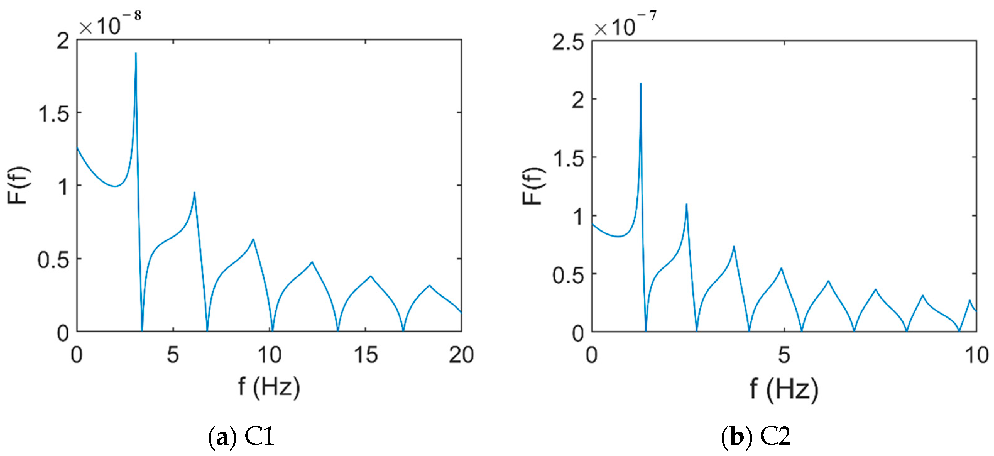
4. Accuracy Verification of the Characteristic Frequency Equation of the Cable-Damper System

In order to verify the accuracy of the characteristic frequency equation of the cable-damper system and the solution method proposed in this paper, the experimental method in the literature [21] and the cable-damper system of a real bridge were used for verification.

4.1. Literature Experimental Verification

The experimental field photos of the cable experiment with damper installed as in the literature [21] are shown in Figure 4. The cable experiment adopts a horizontal cable with a fixed length of 61.8 m at both ends, and the damper is installed at a position l 1 away from the end. Install a load cell on the right end of the cable. During the experiment, the cable between the damper position and the right end is struck with a hammer, and the resulting vibration is measured using an accelerometer installed on the cable. For the validation of this paper, three working conditions were selected for validation, and the tension cable parameters and damper parameters are shown in Table 2.
The measurement frequency, the frequency calculated by the method in this paper and the frequency calculated in the literature are listed in Table 3. The 5th order frequency of the cable-damper system is not measured in the literature, so the corresponding calculation result of the method in this paper is not given.
It can be seen from Table 3 that the frequency of the structural system solved by the characteristic frequency equation proposed in this paper is in good agreement with the frequency results measured by experiment. Under the three cases, except for the frequency errors of the 1st and 6th orders of case 1, which are −3.4% and −3.9%, respectively, the other order errors are less than 2.0%. Compared with the methods in the literature, except for the 5th and 6th order frequencies, the proposed method is superior to the methods in the literature. Especially for the first four modes, the maximum error in the calculation accuracy of the method proposed in this paper is −3.4% for the first order frequency under working condition 1, with the remaining errors all less than 1.7%. In comparison, the method from the literature yields errors greater than 6.6%, with the maximum error reaching −15.0% for the fourth order frequency in case 1. Additionally, the calculated results from the literature show significant variation, with errors for the 6th to 8th order frequencies being smaller than those for the first four orders. In contrast, the method presented in this paper exhibits consistently smaller errors across all frequency orders, demonstrating its superior stability compared to the literature method.

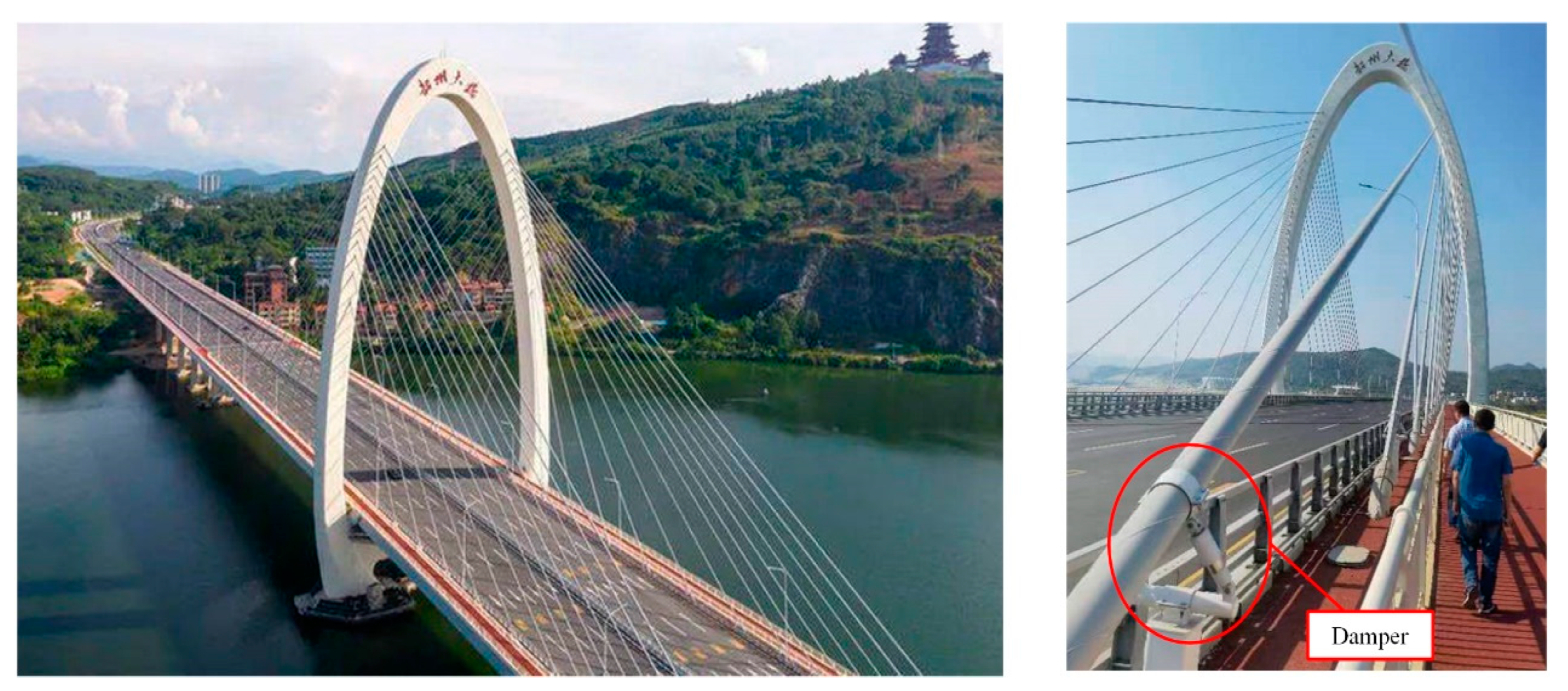
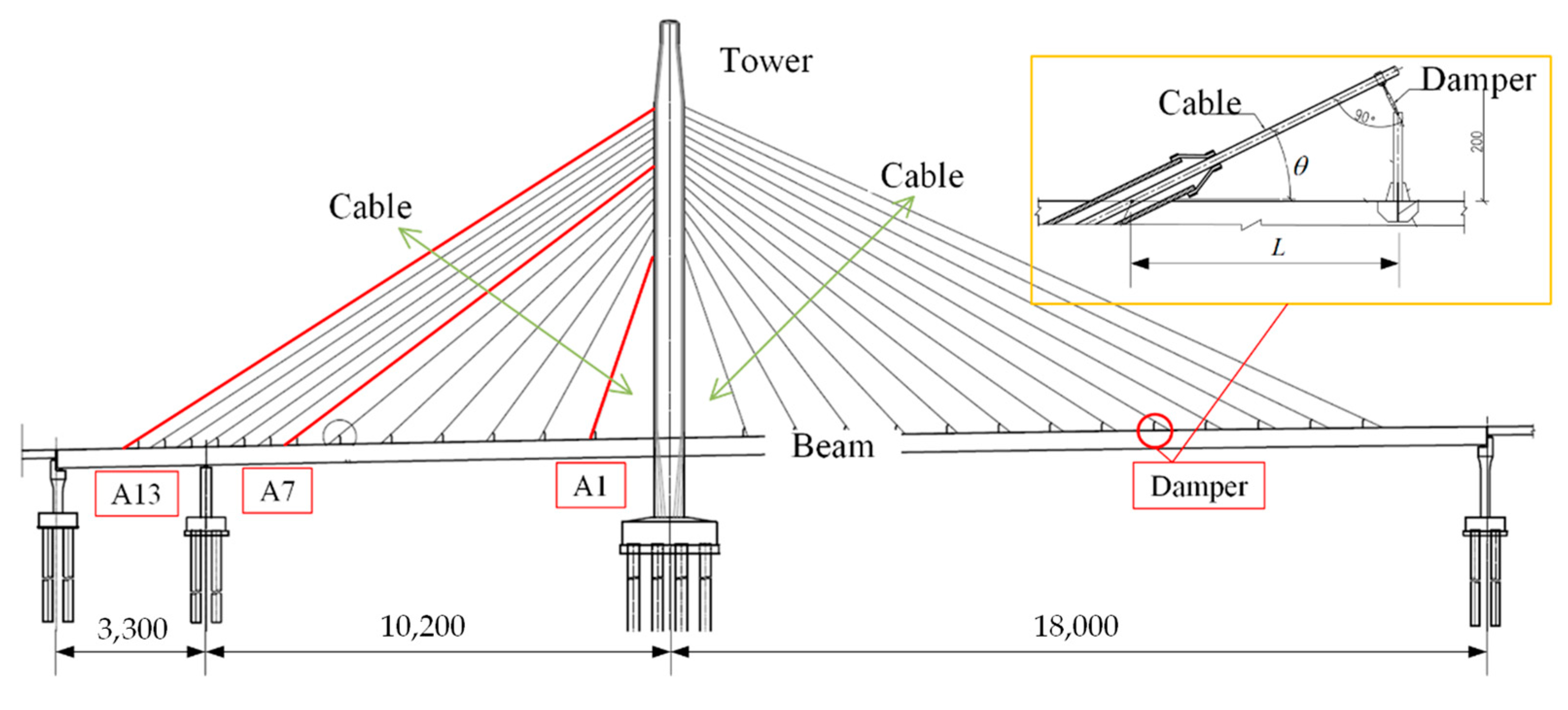
4.2. Real Bridge Data Verification

The specimen used in 4.1 is a steel strand, not an actual cable. In order to further verify the accuracy of the proposed method in the application of the cable-damper system in real bridges, this paper selected the cable-damper system of Shaozhou Bridge in Guangdong Province, China for analysis.
The main bridge of Shaozhou Bridge adopts steel–concrete composite beams with a single tower and double cable surface. The span arrangement of the bridge is 33 + 102 + 183 = 318 m, and the whole bridge adopts a half-floating system. The main beam adopts a streamlined flat box beam; the cable tower adopts an arched bridge tower, and the tower column is a reinforced concrete component. The whole bridge has 26 pairs of cables, a total of 52 cables. In the concrete beam section, the distance between the cables is 6 m; in the steel box beam section, the distance between the cables is 12 m, and the vertical distance on the tower between the cables is 2.0 m. The cable-stayed cable adopts the type 250 high-strength epoxy-coated steel strand diagonal cable; the standard strength is 1860 MPa, and the cable group anchor system is adopted. To suppress cable vibrations, an external passive damper is installed near the cable beam section. Figure 5 illustrates the structural layout of the bridge, while Figure 6 shows the installation of the cable dampers
Considering the influence of different cable lengths, the A1, A7, and A13 cables of Shaozhou Bridge are selected for analysis. Table 4 outlines the key parameters of the cable-damper system for the cables analyzed in Shaozhou Bridge. Accelerometers are installed on the above three cables, and the sampling frequency is 50 Hz. In order to reduce the impact of vehicle load, the data at 2:00 a.m. on 1 July 2023 were selected for analysis, and the acceleration data duration was 5 min. The acceleration signal time-history curve and acceleration amplitude spectrogram are illustrated in Figure 7.
Table 5 presents the measured cable frequencies derived from the analysis in Figure 7, along with the cable frequencies calculated using the method proposed in this paper, based on the parameters in Table 4.
As can be seen from Table 5, the frequency of the cable-damper system calculated by the method in this paper is in good agreement with the measured frequencies, and the calculation errors are less than 1.7%. This verifies that the characteristic frequency equation proposed in this paper has a high precision and can accurately analyze the dynamic characteristics of the cable-damper system.

5. Influence of Damper Parameters on Dynamic Characteristics of Cable

It is important to analyze the effect of damper parameters on the frequency of the cable-damper system when designing dampers for vibration modes where controlling the frequency of the cable is the primary concern. This section utilizes the frequency characteristic function of the cable-damper system proposed in this paper to analyze the effects of damper parameters, such as damping coefficient, stiffness, and installation height, on the cable frequencies. The analysis aims to determine how different damper design parameters influence the dynamic characteristics of the system, providing a basis for the design of the cable-damper system.

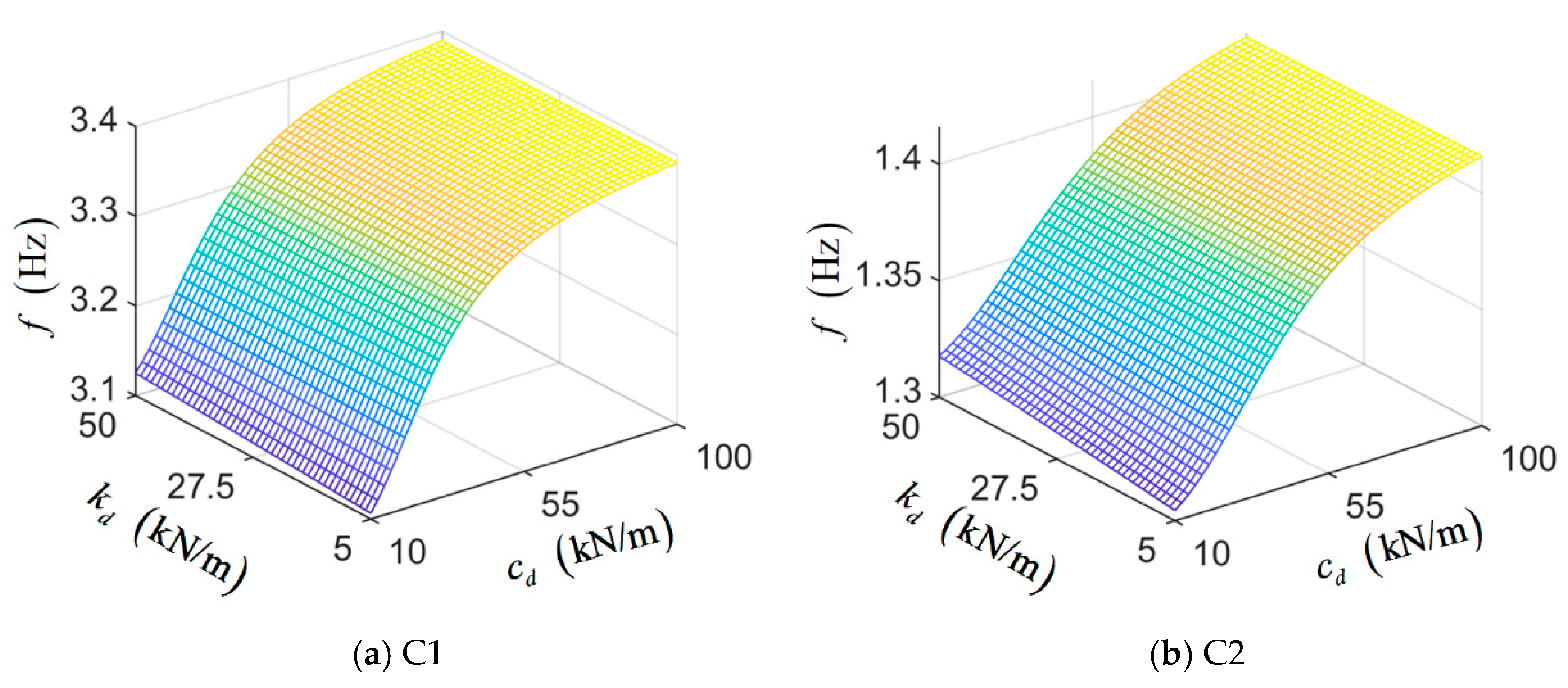
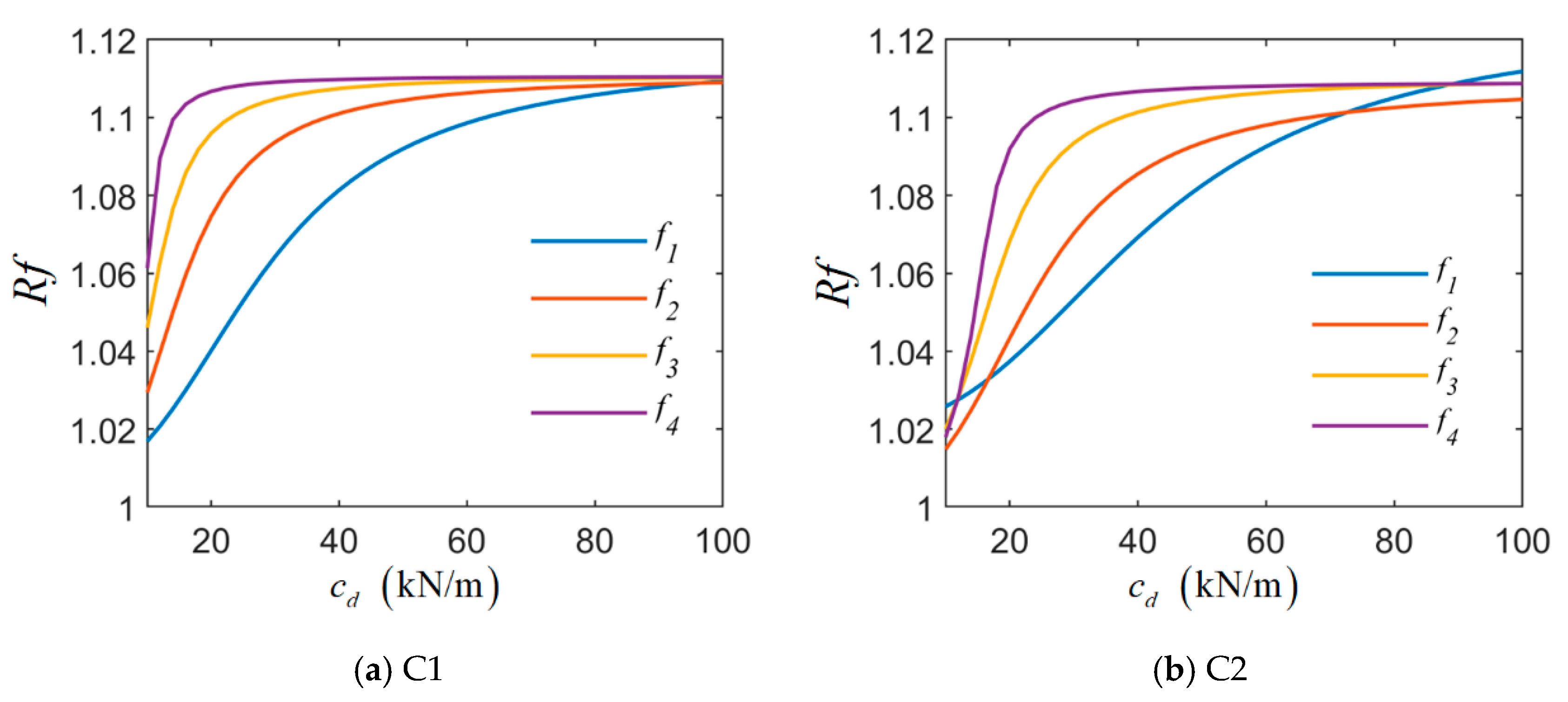
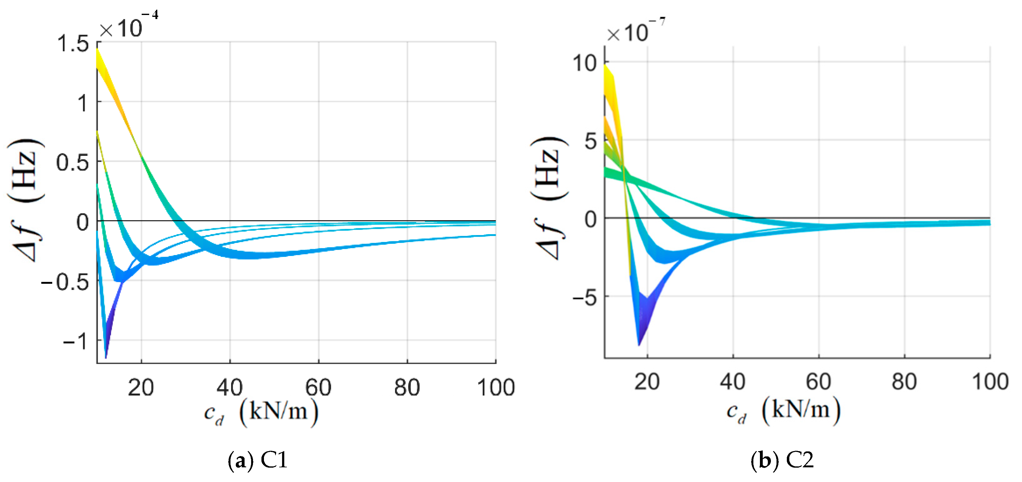
5.1. Influence of Damper Stiffness and Damping Coefficient on Cable Frequency

In analyzing the effect of the damper stiffness and damping coefficient on cable frequency, the parameters for the two cables are selected from Table 1. The external damper is mainly used to control the low-order vibration of the cable [22]. Therefore, this paper examines how the first four order frequencies of the cable vary with changes in the damper’s stiffness and damping coefficient. Among them, the stiffness of the damper varies from 0.5 k d to 5 k d , and the change interval is 0.1 k d . The damping coefficient varies from 0.5 c d to 5 c d , and the variation interval is 0.1 c d . The variation of the first order frequency of the cable-damper system with damper stiffness and damping coefficient is given in Figure 8.
As can be seen from Figure 8, the influence of the damper damping coefficient on system frequency is much greater than that of damper stiffness. Under different k d , the damping coefficient has a smaller effect on the cable frequency. As the damping coefficient increases, the system frequency also rises. The influence of damper stiffness on cable frequency is different under different c d . When c d is small, k d has a significant effect on frequency. For the C1 cable, the maximum influence amplitude is 0.6%, and the C2 cable maximum influence amplitude can reach 1%.
To further analyze the effect of the damping coefficient on the first four frequencies of the cable, the relative frequency ratio index (Equation (15)) was defined, and the four frequencies were normalized. The first four frequencies results of the two cables are shown in Figure 9, and the damper stiffness is 10 kN/m. For comparison, this paper examines the first four natural frequencies of the cable when the damping coefficient is infinite, effectively treating the cable as a rigidly supported structure at the damper location. The results are presented in Table 6.
R f = f d f c
where f d is the calculated frequency of the system, and f c is the calculated frequency of the cable without damper.
From Figure 9, it can be seen that when the damper stiffness is determined, as the damping coefficient increases, the first four orders of the frequencies of the cable are increased, and the final increases in amplitude are all near 10%. However, when the damping coefficient increases to a certain value, the cable frequency tends to be stable and no longer increases. The value of Rf is close to that of the cable frequency when it is rigidly supported. This corresponds to the optimal damping coefficient that enhances the cable frequency. Beyond this point, increasing the damping coefficient further will not significantly increase the stiffness of the cable-damper system. This corresponds to the optimal damping coefficient of the damper at this frequency, representing the minimum damping required to prevent a significant increase in the stiffness of the cable-damper system. With the increase in frequency order, the optimal damping coefficient of cable frequency decreases. When the optimal damping coefficient is reached, increasing the damping coefficient has no significant effect on the adjustment of the cable-damper system stiffness. This shows that the damping coefficient should be selected according to the target order frequency in the actual design of a cable-damper system. The lower the frequency order, the greater the damping coefficient required to achieve the same frequency increase.
As can be seen from Figure 8, the effect of damper stiffness on the cable frequency is influenced by the damping coefficient. Therefore, this paper analyzes the influence of damper stiffness variation on cable frequency when corresponding to different damping coefficients. The frequency difference index Δ f (Equation (16)) is defined for analysis. When Δ f > 0, the contribution of damper stiffness to cable stiffness is positive; when Δ f <0, the contribution of damper stiffness to cable stiffness is negative. Figure 10 shows the variation of frequency difference index with damping coefficient. In Figure 10, Δ f reflects the change value of frequency with each change of 0.1 k d . The farther the frequency deviates from the 0 axis, the greater the influence.
Δ f n k , n c = f k d , n k + 1 , c d , n c f k d , n k , c d , n c
where n k = 1–45 is the order of values of k d ; n c = 1–46 is the order of values of c d ; f k d , n k , c d , n c is the frequency of the cable-damper system calculated using the n k th k d and n c th c d .
It can be seen from Figure 10 that with the increase in the damping coefficient, the contribution of k d to the first 4th-order frequencies of the lasso shows a decreasing (positive contribution)-increasing (negative contribution)-decreasing (negative contribution) trend. When the damping coefficient is between 10 and 40 kN/m, the effect of the damper stiffness on the system frequency is most pronounced. In this paper, c d is defined as the critical damping coefficient of damper stiffness when crossing the 0 axis. When the damping coefficient is less than c d , the stiffness of the system increases with the increase in k d , and the increase in k d makes a positive contribution to the stiffness of the system. When the damping coefficient is greater than c d , the stiffness of the system decreases with the increase in k d , and the increase in dk makes a negative contribution to the stiffness of the system. With the increase in frequency order, the c d decreases. When c d exceeds 40 kN/m, the influence of the change in k d on the first four frequencies of the system tends to be stable and small. This shows that when the damping coefficient is large enough, the influence of the damper stiffness on the stiffness of the system can be ignored.

5.2. Influence of Damper Installation Height on Cable Frequency

Considering that the lower end of the external damper is typically fixed to the main beam, the installation height of the damper is generally kept low when analyzing its impact on the cable frequency. Therefore, this paper analyzes the first four order frequencies of the cable when the installation height of the damper changes from 0.01 l 0 to 0.1 l 0 . To assess the influence of the damper’s stiffness and damping coefficient on the frequency, three different working conditions are considered: case 1, k d = 0, c d = 20 kN/m; case 2, k d = 10 kN/m, c d = 0; and case 3, k d = 10 kN/m, c d = 20 kN/m. The analysis results of how the first four order frequencies of the two cables change with the installation height of the damper under the three working conditions are shown in Figure 11.
From Figure 11, except for the first order frequency of the C2 cable in Case 2, the first four order frequencies of the cable all increase with the installation height of the damper. This shows that, the higher the damper is installed, the more beneficial it is to increase cable stiffness. As seen in Figure 11a,b, when only the damping coefficient is considered, the impact of installation height on frequency increases exponentially. The effect on high-order frequencies is more significant than that on low-order frequencies. The increase in frequency at 0.1 l 0 installation height is nearly 12% higher than that at 0.01 l 0 installation height. It can be seen from Figure 11c,d that, when only the stiffness of the damper is considered, when the height of the damper is relatively small, k d will weaken the system stiffness, which is unfavorable to the system. For the short cable C1, when the installation height is around 0.02 l 0 , the influence on the first four order frequencies is positive. For the long cable C2, when the installation height is around 0.065 l 0 , the influence on the first four order frequencies is positive. It can be observed that, compared to the short cable, the installation height required for the long cable is greater. However, from the perspective of influence amplitude, when k d is fixed, the influence of μ on the first four order frequencies of the two cables is less than 0.3%. It can be seen from Figure 11a–d that the influence of k d on system frequency can be ignored compared with the influence of c d on system frequency. Therefore, in Figure 11e,f, when the damper has both damping coefficient and stiffness, the influence on the cable-damper system is mainly guided by the damping coefficient of the damper, and its variation rule is similar to that of Figure 11a,b.
In summary, in the system, the damping coefficient of the damper and the installation height of the damper have the most significant influence on the system, while the damper stiffness has relatively little influence on the system. In the design of damper parameters, the damping coefficient and installation height should be taken as the main design parameters, and the damper stiffness should be secondary.

6. Discussion

Based on the dynamic stiffness method, this paper presents an accurate dynamic analysis approach for the cable-damper system. By considering factors such as cable bending stiffness, sag, inclination angle, cable force, and mass per unit length, along with damper stiffness, damping coefficient, and installation height, the proposed method provides a more realistic representation of the cable-damper system as found in actual bridges. The proposed method is more accurate for the frequency analysis of the cable-damper system in comparison to the experimental results of the literature and the results from the real bridge. By analyzing the influence of damper parameters on the dynamic characteristics of the system, the following conclusions are obtained:
(1)
The damping coefficient and installation height of the damper significantly influence the dynamic behavior of the cable, whereas the damper stiffness has a relatively minor effect. The analysis indicates that variations in the damping coefficient and installation height can lead to frequency changes exceeding 10%, with the impact increasing at higher vibration modes. The impact of damper stiffness on frequency is less than 1%; the impact on long cable is greater than that of short cable, and the impact on the first order frequency is higher than the impact on other order frequencies.
(2)
As the damping coefficient and installation height of the damper increase, the frequency of each mode of the cable also rises. For different order frequencies, there is an optimal damping coefficient. When the optimal damping coefficient is reached, increasing the damping coefficient has little effect on increasing the cable stiffness. As the order increases, the optimal damping coefficient decreases. When the damper is installed within 0.1 L, the damper’s contribution to the stiffness of the system increases exponentially.
(3)
The influence of the damper stiffness on the dynamic characteristics of the cable is affected by the damping coefficient of the damper, and there is a critical damping coefficient. As the cable order increases, the critical damping coefficient decreases. When the damping coefficient is less than the critical coefficient, increasing the damper stiffness will increase the stiffness of the system. When the damping coefficient exceeds the critical damping value, increasing the damper stiffness reduces the overall stiffness of the cable system. However, once the damping coefficient is sufficiently large, the effect of damper stiffness on the dynamic characteristics of the cable becomes negligible, and its influence on the system frequency stabilizes.
This paper mainly shows the application of the proposed method in the dynamic characteristic analysis of the cable-damper system. This method enhances the design, safety, and longevity of cable-stayed bridges by providing more accurate predictions of dynamic behavior, optimizing damper placement, and supporting better maintenance strategies. In addition, from the proposed cable frequency characteristic equation, it includes cable frequency, cable force, cable parameters, and damper parameters. Therefore, it has great potential to be applied to cable parameter identification and damper effect evaluation. From the analysis results of this paper, it can be seen that the damper has a relatively large impact on the frequency of the cable. If the cable parameter identification method without a damper is used, the identification results will inevitably have large errors. The method proposed in this paper can provide a better solution to this kind of problem, which is also the direction of the authors’ next work.
To further strengthen the discussion, future research directions could focus on expanding the dynamic analysis method to account for additional parameters that influence the behavior of cable-damper systems. For example, investigating the effects of varying environmental conditions, such as temperature fluctuations and wind speed changes, on the dynamic response of cables could provide deeper insights into the long-term performance and reliability of the system. Additionally, refining the modeling approach to incorporate more complex nonlinearities or to analyze the interaction between multiple cables and dampers in large-scale bridge networks could enhance the applicability of the method to a wider range of real-world scenarios.

Author Contributions

Conceptualization, H.J. and H.Y.; Methodology, H.J., B.X., Z.J., C.C. and H.Y.; Software, H.J. and Z.J.; Validation, H.J., Z.J. and H.Y.; Formal analysis, C.C. and H.Y.; Investigation, H.Y.; Resources, Z.J.; Data curation, H.J., B.X., Z.J. and H.Y.; Writing—original draft, H.J., B.X., Z.J. and H.Y.; Writing—review & editing, H.J., B.X., C.C. and H.Y.; Visualization, H.Y.; Supervision, Z.J.; Project administration, Z.J., C.C. and H.Y.; Funding acquisition, C.C. All authors have read and agreed to the published version of the manuscript.

Funding

This research was funded by the National Natural Science Foundation of China (Grant No. 52108290); the China Postdoctoral Science Foundation (Grant No. 2022 M712906); the Foundation of Henan Educational Committee (Grant No. 242102240131).

Data Availability Statement

The data presented in this study are available on request from the corresponding author.

Conflicts of Interest

Authors Hui Jiao and Zhengkai Jiang were employed by the company Investment Company of China Railway Seventh Group Co., Ltd. The remaining authors declare that the research was conducted in the absence of any commercial or financial relationships that could be construed as a potential conflict of interest.

References

  1. Larsen, A.; Larose, G.L. Dynamic Wind Effects on Suspension and Cable-Stayed Bridges. J. Sound Vib. 2015, 334, 2–28. [Google Scholar] [CrossRef]
  2. Fujino, Y.; Siringoringo, D. Vibration Mechanisms and Controls of Long-Span Bridges: A Review. Struct. Eng. Int. 2013, 23, 248–268. [Google Scholar] [CrossRef]
  3. Sun, P.; Wang, S.; Wang, D. The Numerical Calculation Method Based on Equivalent Frequency-Independent Time-Domain Damping Model. J. Low Freq. Noise Vib. Act. Control 2022, 41, 1339–1353. [Google Scholar] [CrossRef]
  4. Wang, S.; He, J.; Fan, J.; Sun, P.; Wang, D. A Time-Domain Method for Free Vibration Responses of an Equivalent Viscous Damped System Based on a Complex Damping Model. Vib. Act. Control. 2023, 42, 1531–1540. [Google Scholar] [CrossRef]
  5. Fournier, J.A.; Cheng, S. Impact of Damper Stiffness and Damper Support Stiffness on the Efficiency of a Linear Viscous Damper in Controlling Stay Cable Vibrations. J. Bridge Eng. 2014, 19, 04013022. [Google Scholar] [CrossRef]
  6. Pacheco, B.M.; Fujino, Y.; Sulekh, A. Estimation Curve for Modal Damping in Stay Cables with Viscous Damper. J. Struct. Eng. 1993, 119, 1961–1979. [Google Scholar] [CrossRef]
  7. Krenk, S. Vibrations of a Taut Cable with an External Damper. J. Appl. Mech. 2000, 67, 772–776. [Google Scholar] [CrossRef]
  8. Lu, Q.; Sun, Z.; Zhang, W. Nonlinear Parametric Vibration with Different Orders of Small Parameters for Stayed Cables. Eng. Struct. 2020, 224, 111198. [Google Scholar] [CrossRef]
  9. Krenk, S.; Nielsen, S.R.K. Vibrations of a Shallow Cable with a Viscous Damper. Proc. R. Soc. London. Ser. A Math. Phys. Eng. Sci. 2001, 458, 339–357. [Google Scholar] [CrossRef]
  10. Main, J.A.; Jones, N.P. Vibration of Tensioned Beams with Intermediate Damper. II: Damper near a Support. J. Eng. Mech. 2007, 133, 379–388. [Google Scholar] [CrossRef]
  11. Sun, L.; Xu, Y.; Chen, L. Damping Effects of Nonlinear Dampers on a Shallow Cable. Eng. Struct. 2019, 196, 109305. [Google Scholar] [CrossRef]
  12. Mehrabi, A.B.; Tabatabai, H. Unified Finite Difference Formulation for Free Vibration of Cables. J. Struct. Eng. 1998, 124, 1313–1322. [Google Scholar] [CrossRef]
  13. Fujino, Y.; Hoang, N. Design Formulas for Damping of a Stay Cable with a Damper. J. Struct. Eng. 2008, 134, 269–278. [Google Scholar] [CrossRef]
  14. Javanbakht, M.; Cheng, S.; Ghrib, F. Control-Oriented Model for the Dynamic Response of a Damped Cable. J. Sound Vib. 2019, 442, 249–267. [Google Scholar] [CrossRef]
  15. Zhou, Q.; Nielsen, S.R.K.; Qu, W. Stochastic Response of an Inclined Shallow Cable with Linear Viscous Dampers under Stochastic Excitation. J. Eng. Mech. 2010, 136, 1411–1421. [Google Scholar] [CrossRef]
  16. Sun, Q.; Zhang, N.; Liu, X. A Dynamic Stiffness Matrix Method for Free Vibrations of Partial-Interaction Composite Beams Based on the Timoshenko Beam Theory. J. Sound Vib. 2022, 520, 116579. [Google Scholar] [CrossRef]
  17. Banerjee, J.R.; Ananthapuvirajah, A. Free Vibration of Functionally Graded Beams and Frameworks Using the Dynamic Stiffness Method. J. Sound Vib. 2018, 422, 34–47. [Google Scholar] [CrossRef]
  18. Li, X.; Cheng, Z.; Wang, Z.; Fan, B. Free Vibration of a Taut Cable with a Parallel-Connected Viscous Mass Damper and a Grounded Cross-Tie. J. Low Freq. Noise Vib. Act. Control 2022, 41, 982–995. [Google Scholar] [CrossRef]
  19. Xu, B.; Dan, D.; Zhao, Y. Frequency-Domain Estimation Method for Vibration-Induced Additional Cable Tension Based on Acceleration Monitoring. J. Vib. Acoust. Trans. ASME 2019, 141, 064502. [Google Scholar] [CrossRef]
  20. Dan, D.-H.; Xu, B.; Chen, Z.-H. Universal Characteristic Frequency Equation for Cable Transverse Component System and Its Universal Numerical Solution. J. Eng. Mech. 2016, 142, 04015105. [Google Scholar] [CrossRef]
  21. Furukawa, A.; Suzuki, S.; Kobayashi, R. Tension Estimation Method for Cable with Damper Using Natural Frequencies with Uncertain Modal Order. Front. Built Environ. 2022, 8, 812999. [Google Scholar] [CrossRef]
  22. Tabatabai, H.; Mehrabi, A.B. Design of Mechanical Viscous Dampers for Stay Cables. J. Bridge Eng. 2000, 5, 114–123. [Google Scholar] [CrossRef]
Figure 1. Cable-damper system mechanical model.
Buildings 14 04007 g001
Figure 2. Force boundary condition and dynamic displacement boundary conditions of the cable.
Buildings 14 04007 g002
Figure 3. Variation curve of characteristic frequency function of cable-damper system with frequency.
Buildings 14 04007 g003
Figure 4. Schematic diagram of experimental setting and photograph of experimental setting [21].
Buildings 14 04007 g004
Figure 5. Shaozhou Bridge site photos.
Buildings 14 04007 g005
Figure 6. The overall layout of Shaozhou Bridge and external damper installation diagram.
Buildings 14 04007 g006
Figure 7. Acceleration history and spectrogram of Shaozhou Bridge cables.
Buildings 14 04007 g007
Figure 8. Influence of damper stiffness and damping coefficient on cable-damper system frequency.
Buildings 14 04007 g008
Figure 9. Influence of damping coefficient on cable frequency.
Buildings 14 04007 g009
Figure 10. Influence of damper stiffness on cable frequency.
Buildings 14 04007 g010
Figure 11. Effect of damper installation height on cable frequency.
Buildings 14 04007 g011
Table 1. Cable-damper system parameters.
Cable l 0 m m k g / m D m θ (°) E I k N m 2 H k N μ 1 k d k g / m c d k g / m
C130450.160602.515000.11020
C280650.250363.525000.11020
Table 2. Parameters of experimental cable-damper system in the literature [21].
Cases l 0 m m k g / m D m E I k N m 2 H k N μ 1 = l 1 l 0 k d k g / m c d k g / m
1377.9261.84.263.2190.02860.1529.317.9
2376.7561.84.263.2190.02860.1557.131.4
3377.7561.84.263.2190.02860.1584.752.5
Table 3. Comparison of frequency calculations in this paper and in the literature [21].
CasesOrder12345678
1Measured value2.935.678.6411.57-14.8017.3220.03
This paper2.835.688.5311.37-14.2317.0319.91
Literature2.555.067.499.84-14.4816.8819.33
Error1 (%)−3.4%0.2%−1.3%−1.7%-−3.9%−1.7%−0.6%
Error2 (%)−13.0%−10.8%−13.3%−15.0%-−2.2%−2.5%−3.5%
2Measured value2.865.758.6411.53-14.5117.3320.21
This paper2.835.678.5111.36-14.2117.0319.88
Literature2.625.217.7110.04-14.4716.8619.33
Error1 (%)−0.9%−1.3%−1.5%−1.5%-−2.0%−1.7%−1.6%
Error2 (%)−8.4%−9.4%−10.8%−12.9%-−0.3%−2.7%−4.4%
3Measured value2.865.758.6411.56-14.4817.3620.25
This paper2.845.688.5311.37-14.2217.0619.91
Literature2.675.317.8710.23-14.5016.8819.38
Error1 (%)−0.7%−1.2%−1.3%−1.6%-−1.8%−1.7%−1.7%
Error2 (%)−6.6%−7.7%−8.9%−11.5%-0.1%−2.8%−4.3%
Note: Error1 is the relative error between the measured value and this paper. Error2 is the relative error between the measured value and the literature method.
Table 4. Parameters of cable-damper system of Shaozhou Bridge.
Cable l 0 m m k g / m D m θ(°) E I k N m 2 H k N μ 1 c d k g / m
A155.252.60.16069.746250923480.065200
A7108.667.50.16036.778200732110.0481000
A13147.4113.30.22432.375462766940.0382300
Table 5. Cable frequency results of the real bridge.
CableOrder12345678
A1Measured2.1704.2946.3488.75911.04413.47116.26918.884
This paper2.1674.2566.4588.72511.09013.56816.17818.937
Error (%)−0.1−0.91.7−0.40.40.7−0.60.3
A7Measured1.0852.1733.2474.3125.3776.5197.5628.633
This paper1.0812.1373.2114.2895.3756.4707.5768.695
Error (%)−0.3−1.7−1.1−0.50.0−0.70.20.7
A13Measured0.8791.7462.6213.5034.3645.2376.1256.958
This paper0.8791.7302.5983.4674.3415.2196.1026.991
Error (%)0.0−0.9−0.9−1.0−0.5−0.3−0.40.5
Table 6. Cable frequency of cable with stiffness support.
CableOrder 1Order 2Order 3Order 4
C13.3966.78310.17513.568
Rf1.1111.1111.1121.112
C21.4022.7324.0955.461
Rf1.1111.1111.1111.111
Disclaimer/Publisher’s Note: The statements, opinions and data contained in all publications are solely those of the individual author(s) and contributor(s) and not of MDPI and/or the editor(s). MDPI and/or the editor(s) disclaim responsibility for any injury to people or property resulting from any ideas, methods, instructions or products referred to in the content.

