Abstract
Utilizing crushed spontaneous combustion coal gangue as a coarse aggregate in concrete preparation effectively reduces reliance on natural resources and mitigates environmental pollution; however, the suboptimal workability of spontaneous combustion coal gangue coarse aggregate concrete (SCG-CAC) limits its engineering applications. To address this issue, this study places SCGCAC at the center of a CFDST (Concrete-Filled Double-Skin Steel Tubular) stub column. Through finite element modeling validated for reliability, this study examines the structural mechanical response to axial loading, along with the effects of various parameters. The analysis encompasses parameters such as the strength of the core SCGCAC (fc,i), the strength of the sandwiched concrete (fc,o), the yield strength of the outer steel tube (fy,o), the yield strength of the inner steel tube (fy,i), the width-to-thickness ratio (B/to), the diameter-to-thickness ratio of the inner tube (D/ti), and the diameter-to-width ratio of the outer tube (D/B). Results show that this structural configuration significantly enhances the core SCGCAC ultimate bearing capacity, and increases in D/ti, fc,i, fc,o, fy,i, and B/to all lead to an increase in the peak load. Particularly, when D/ti increases from 28.57 to 80, the peak load increases by 42.72%. However, changes in fy,o and D/B have no significant effect on the peak load.
1. Introduction
Coal gangue, the main solid waste product produced in the coal mining and processing phase [1,2,3,4,5,6], can be repurposed into concrete to reduce dependence on natural aggregates and environmental pollution from disposal. However, its high water absorption may negatively impact concrete workability and the interfacial properties of coal gangue concrete, making it less favorable compared to natural aggregate concrete [7,8,9]. To improve the mechanical properties and durability, the coal gangue coarse aggregate concrete-filled steel tubular (CGCACFST) has been developed [10,11,12,13,14], offering benefits including high strength, ductility, and earthquake resilience. As high-strength steel and concrete technologies advance, traditional concrete-filled steel tubular (CFST) columns have seen a reduction in cross-sectional size, which can compromise fire resistance. The double-skin steel tubular (CFDST) column, with its dual-tube structure, enhances fire endurance and flexural stiffness, effectively safeguarding the internal concrete. This architectural approach is gaining popularity for its application in the erection of high-rise buildings and the construction of bridges [15,16,17,18,19].
Currently, researchers have explored the compressive axial behavior of CFDST stub columns, featuring diverse cross-sectional shapes. Wang and Tao et al. [20] developed a finite element model to assess the interaction between the concrete and the steel tube, considering variables such as the diameter and thickness of the inner tube, along with the strength of the sandwiched and core concrete. Expanding on additional parametric analyses, a model was introduced based on super-position to ascertain the compressive axial strength of CFDST stub columns. Ahmed et al. [21] combined experimental and numerical simulation methods to assess the impact of dimensions of cross-sections, the inner and outer tube’s width-to-thickness ratios, and the eccentricity of loading on the axial compressive behavior of square thin-walled CFDST stub columns. A mathematical model for predicting the moment–curvature relationship and determining the strength envelopes of CFDST structures was developed and later validated with experimental data. Zheng and Tao et al. [22] explored the axial compression response of CFDST stub columns, examining their ultimate strength, strain, and stiffness. Incorporating frameworks of the finite element method, the refined model was designed to model the effect of circular CFDST stub columns. This research resulted in the formulation of design expressions to calculate the columns’ axial load capacity. Ci et al. [23] developed a computational model specific to square CFDST stubs. This model analyzed the impact of concrete strength, width-to-thickness ratios, diameter-to-thickness ratios, and yield strength on the columns’ performance through parametric studies. The development of a novel formula for calculating the ultimate axial load capacity of CFDST stub columns was a result of the research. The results showed that the formula effectively predicts the columns’ strength. Liang et al. [24] developed a circular CFDST short-column fiber model, focusing on the nonlinear response to axial compression, which is influenced by the outer tube’s thickness-to-diameter ratio, the compressive strength of concrete, and the steel tube’s yield strength. The proposed design expressions for the concrete confinement effect demonstrated that this fiber model and the accompanying design expressions effectively predict the load-bearing capacity and behavior of CFDST columns. Summarizing the research, studies on CFDST columns’ axial compressive behavior have focused on the performance of dimensions for the steel tubes, both inner and outer, as well as on structural strength, stiffness, and ductility. Furthermore, the research has delved into the impact of eccentric loading and local buckling on component failure. These insights have driven the creation of finite element models for modeling the nonlinear response in CFDST columns, which has guided the development of methods to evaluate their ultimate bearing strength.
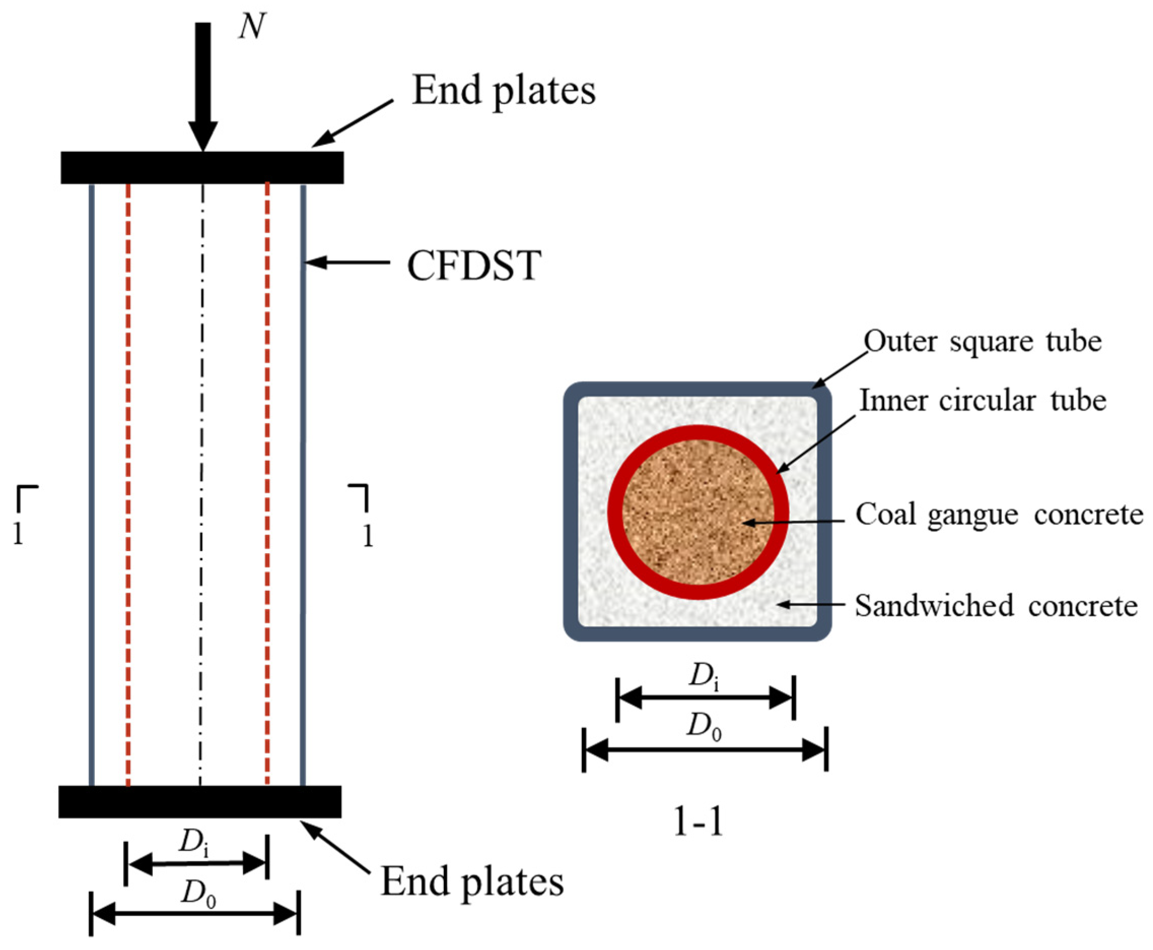
Investigations into the axial compressive mechanical property and confinement effects of spontaneous combustion coal gangue coarse aggregate concrete-filled double-skin steel tubular (SCGCA-CFDST) stub columns remain scant. To clarify the compressive behavior in the axial direction of SCGCA-CFDST stub columns, this paper takes the outer square and inner circular SCGCA-CFDST stub columns as its focal point (as illustrated in Figure 1). Firstly, the SCGCA-CFDST stub column’s finite element model is developed. Following validation of the model’s accuracy, typical SCGCA-CFDST components are selected for force analysis, delving into the load–strain variation law, concrete stress distribution patterns, patterns of yield stress in steel tubes, and mechanisms of interaction at the critical position of concrete. This paper then evaluates the influence of key parameters on the axial compressive behavior of SCGCA-CFDST structures. The parameters include the core SCGCAC’s strength, the sandwiched concrete’s strength, the steel tubes’ yield strength—both inner and outer—as well as the square tube’s width-to-thickness ratio, the circular tube’s diameter-to-thickness ratio, and the ratio of the circular tube’s diameter to the square tube’s side length, referred to as the diameter-to-width ratio. Key factors influencing the load-bearing capacity of SCGCA-CFDST stub columns have been identified. This paper ultimately assesses the applicability of existing formulas in calculating the axial compressive strength of SCGCA-CFDST structures.
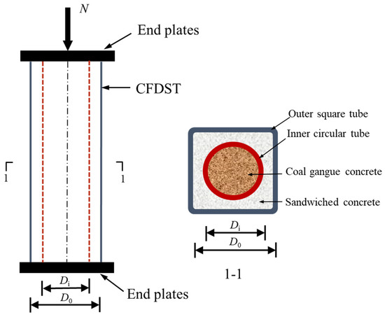
Figure 1.
The SCGCA-CFDST stub column.
2. Establishment of Finite Element Model
2.1. Constitutive Model of Materials
2.1.1. Constitutive Model of Concrete
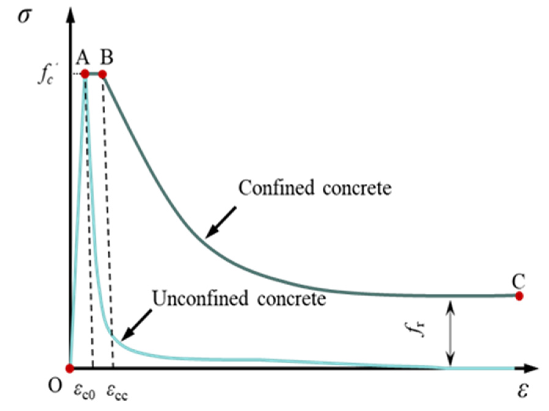
This document employs the model put forth by Samani and Attard [25] to delineate the upward trajectory OA (Figure 2), expressed by the following equations:

Figure 2.
The constitutive behavior of concrete.
In these equations, fc′ represents the compressive strength of concrete in a cylindrical shape under unconfined conditions. The strain experienced by unconfined concrete at the peak of its uniaxial compressive stress (εc0) and the strain at point B within the confined concrete model (εcc) are calculated using the equations developed by Samani and Attard [25].
In this equation, fB represents the value of the confining pressure acting on the confined concrete at the specific point B.
In the descending phase (B-C) of Figure 2, the exponential function that is suggested by Binici [26] is employed and expressed as follows:
In Equation (6), “fr” signifies the remaining stress, while “α” and “β” are coefficients that define the downward-sloping segment. The expression for fr is as follows:
Parameter α is calculated in accordance with Equation (8). In the expression, β for the circular and rectangular cross-sections are 1.2 and 0.92, respectively, where the function of ξc is represented by fr and α.
2.1.2. Constitutive Model of Steel Tube
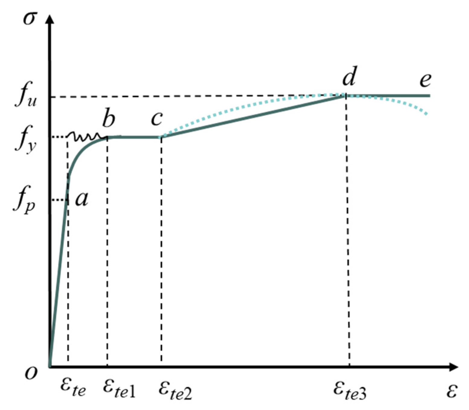
This study utilizes stress–strain behavior models for square and circular steel tubes, as outlined in the existing literature [27,28], to characterize the relationship between stress and strain in steel tubes, as illustrated in Figure 3. The model encompasses five stages: elastic, elastoplastic, plastic, hardening, and fracture. Notably, fp, fy, and fu denote the proportional limit, yield point, and ultimate tensile strength of the steel tube in that order. The dashed line represents the actual stress–strain behavior of the steel material as observed in real-world applications, while the solid line illustrates the simplified stress–strain relationship derived from the model.
In Equation (9), there are the following:
Et: the modulus of elasticity of the steel tube;
Fty: the yield point of the steel tube;
Ftu: the ultimate tensile strength of the steel tube;
εte, εte1, εte2, εte3: the strains corresponding to the end of the elastic, elastoplastic, plastic flow, and strengthening phases in the stress–strain graph of the steel tube, respectively. The computational formulas are as follows:
A, B, C denote the parameters that characterize the stress–strain behavior of the steel tube, and their computational formulas are as follows:
Due to the presence of corner strengthening in cold-formed square steel tubes, the modeling process involves segmenting the square steel tube into flat plate regions and curved corner regions. The bending radius R is determined according to the methodology in the literature [29,30]: when t < 3 mm, R = t; when t ≥ 3 mm, R = 1.5t. The formula below calculates the yield strength of the rounded corner area in a square steel tube(fy1):
In the formula, Bc and m are parameters associated with the ratio of the ultimate tensile strength fu to the yield strength fy of the steel in the flat plate area:
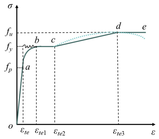
Figure 3.
The constitutive behavior of the steel tube.
Figure 3.
The constitutive behavior of the steel tube.
2.2. Element Type, Meshing, and Boundary Conditions
Both the internal and external steel tubes of the SCGCA-CFDST stub column are represented in the model using four-node shell elements (S4R). Concurrently, the core coal gangue concrete, sandwiched concrete, and end plates are modeled using eight-node linear brick elements (C3D8R), following the specifics outlined in reference [31]. Following trial calculations and the literature suggestions [32], the optimal mesh density was set to one-fifteenth of the outer steel tube’s side length. Given the symmetry in loading and geometry, this study focuses on the boundary conditions for a quarter section of the SCGCA-CFDST stub column model.
Reference points are set at the geometric centers of both the upper and lower plates, with each point being coupled to its respective plate surface. A downward load, N(Δ), is applied along the Z-axis at the reference point of the upper end plate. The displacement is constrained in both the X and Y directions, as well as in rotation. The lower end plate is fully fixed. The load is simulated through the application of displacement [33]. The finite element schematic diagrams for the typical components are displayed in Figure 4.
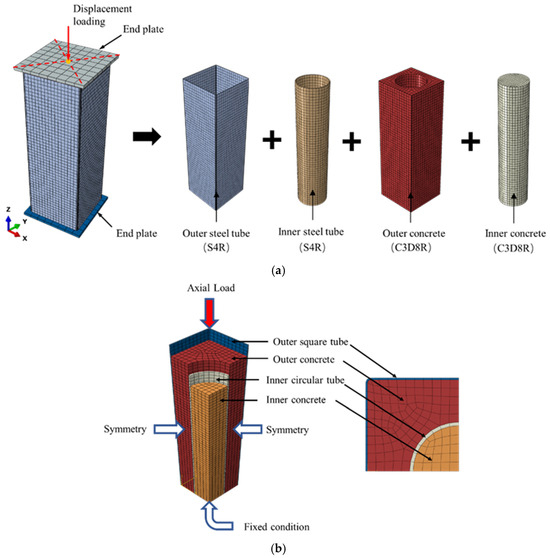
Figure 4.
Typical finite element model diagram. (a) Selection of element types for each part of typical finite element model. (b) Boundary conditions of typical finite element models.
2.3. Definition of Interaction
The interaction between the steel tube and the concrete is modeled employing a “surface-to-surface” contact approach. A “hard contact” algorithm is employed for the normal direction, while the tangential direction is governed by a Coulomb friction model. The friction coefficient for this model is established at 0.6, supported by references [34,35]. The steel tube surface is designated as the primary surface, while the concrete surface is designated as the secondary surface. The interaction between the end plate and the concrete is simulated in a manner similar to the interaction between the steel tube and the concrete. The end plate is connected to the steel tube surface using a “Tie” constraint, which guarantees that the displacement and rotational angles of the contact elements remain consistent during loading, as noted in [36].
2.4. Validation of Finite Element Model
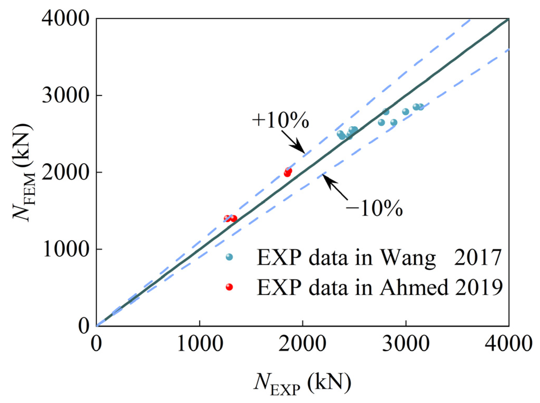
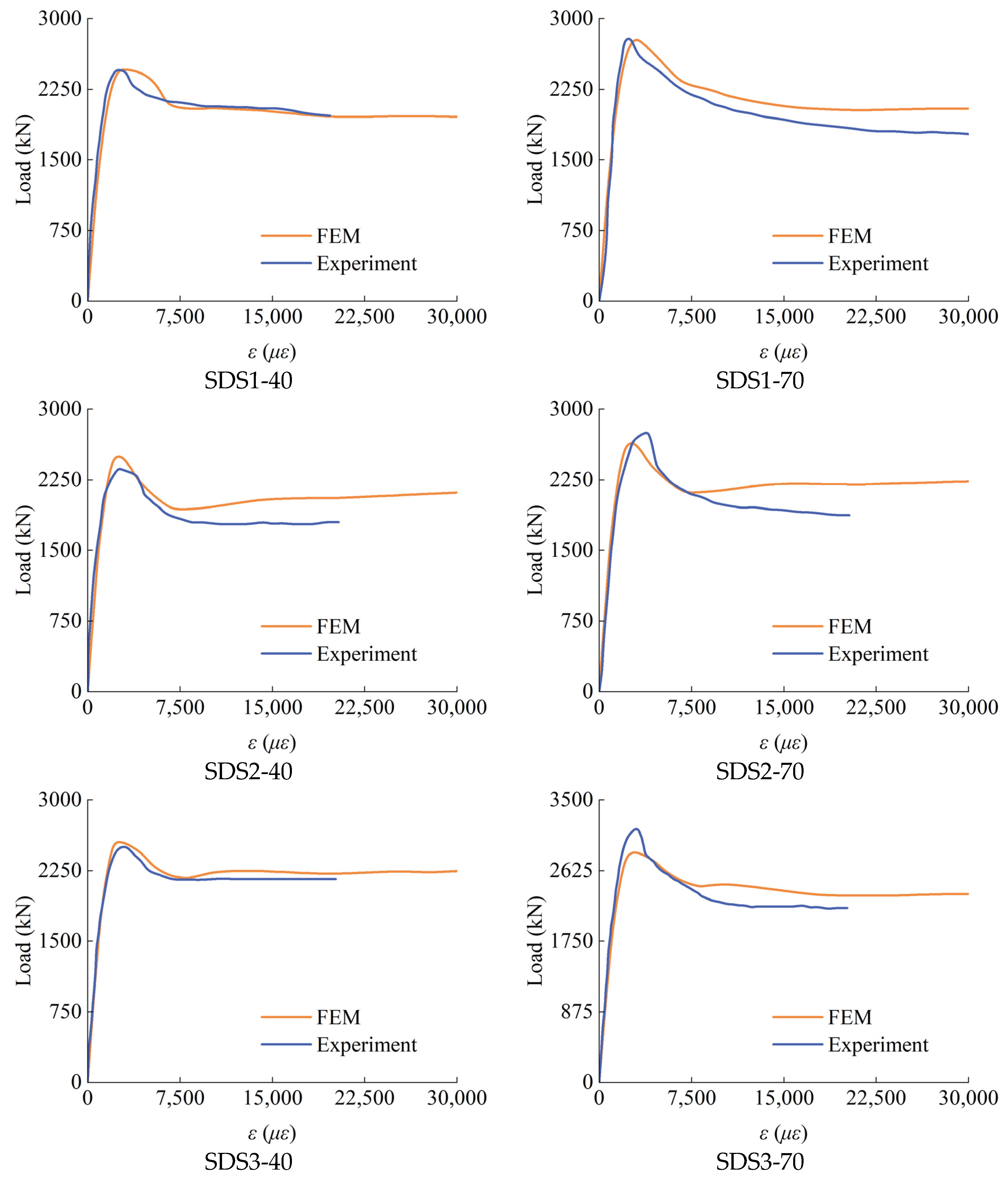
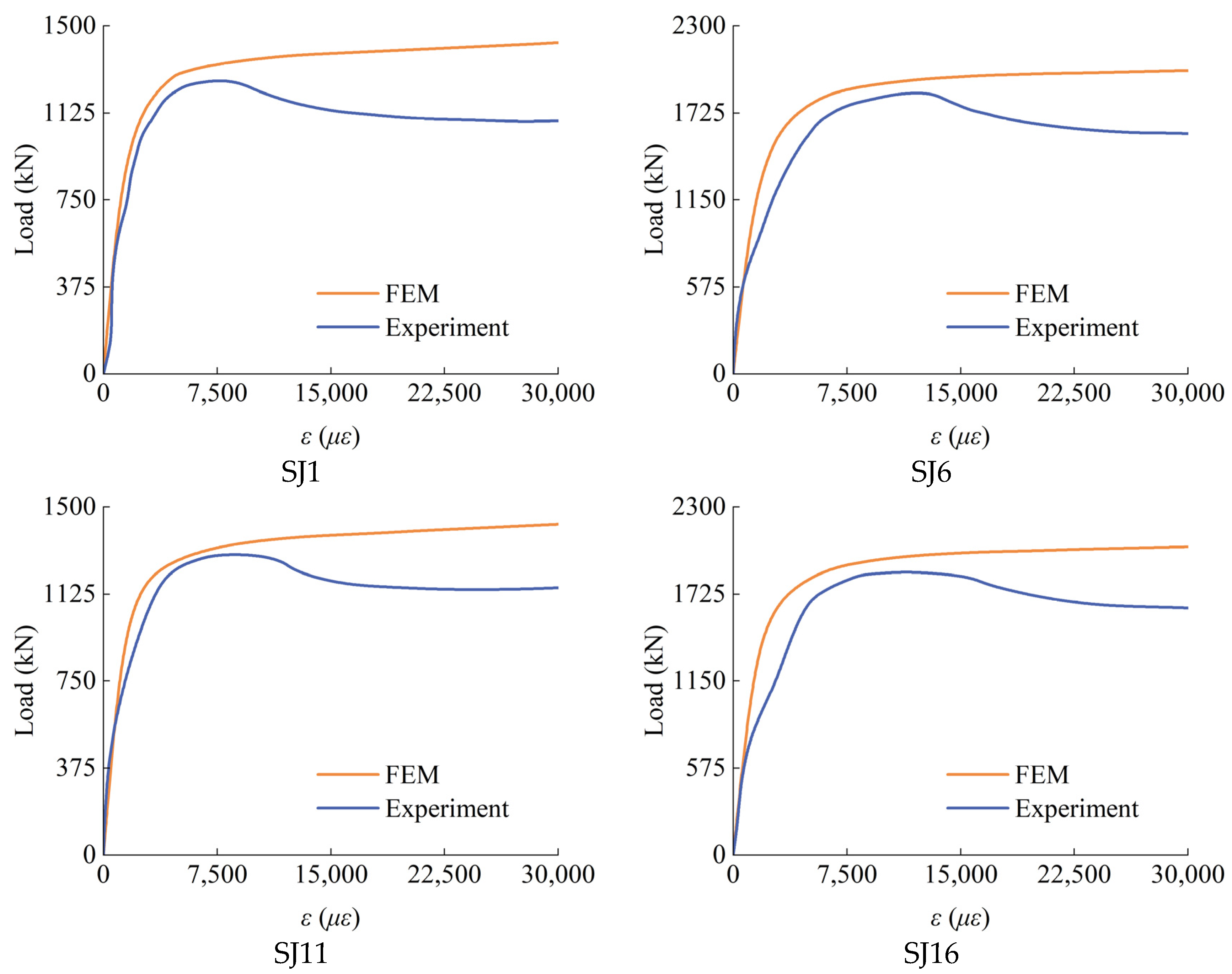
This study incorporates experimental data from [20,21], with specimen dimensions outlined in Table 1. Figure 5 contrasts the simulated (NFEM) and experimental (NEXP) load-bearing capacities of standard specimens. The results show a maximum error of 10.20%, a minimum of 0.59%, and an average absolute error of 2.21%. Additionally, Figure 6 illustrates the correlation between axial load and longitudinal strain during the entire loading phase. The outcomes of the finite element analysis demonstrate a commendable alignment with the experimental outcomes. However, the initial slope is excessively steep, which can be attributed to the finite element analysis model failing to adequately account for initial imperfections in the specimen and microscopic gaps within the loading apparatus. A similar phenomenon is observed in reference [31]. In Table 1, B0 and D0 denote the cross-sectional dimensions of the outer steel tube, specifically its width and length; Di represents the diameter of the inner steel tube; t0 denotes the wall thickness of the outer steel tube; and ti signifies the wall thickness of the inner steel tube. The terms fyo, fco′, and fci′ correspond to the yield strength of the outer steel tube, the strength of the outer concrete cylinder, and the compressive strength of the inner concrete cylinder, respectively. Additionally, Pu,exp and Pu,fem denote the experimentally determined peak load capacity and the simulated peak load capacity, respectively.

Table 1.
Ultimate axial load predictions vs. experiments for square CFDST stub columns.

Figure 5.
Comparison between empirical data and computational simulation outcomes in [20,21].
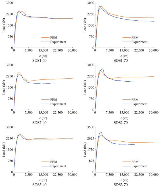
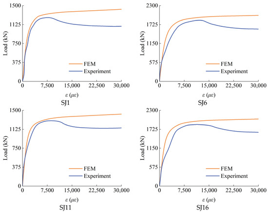
Figure 6.
Comparison of the load–strain curves obtained from experimental tests and those generated through simulation.
3. Analysis of Axial Compression Behavior Mechanism of SCGCA-CFST Stub Column
3.1. Relationship Between Load and Strain of Each Part of the Structure During Axial Loading Process
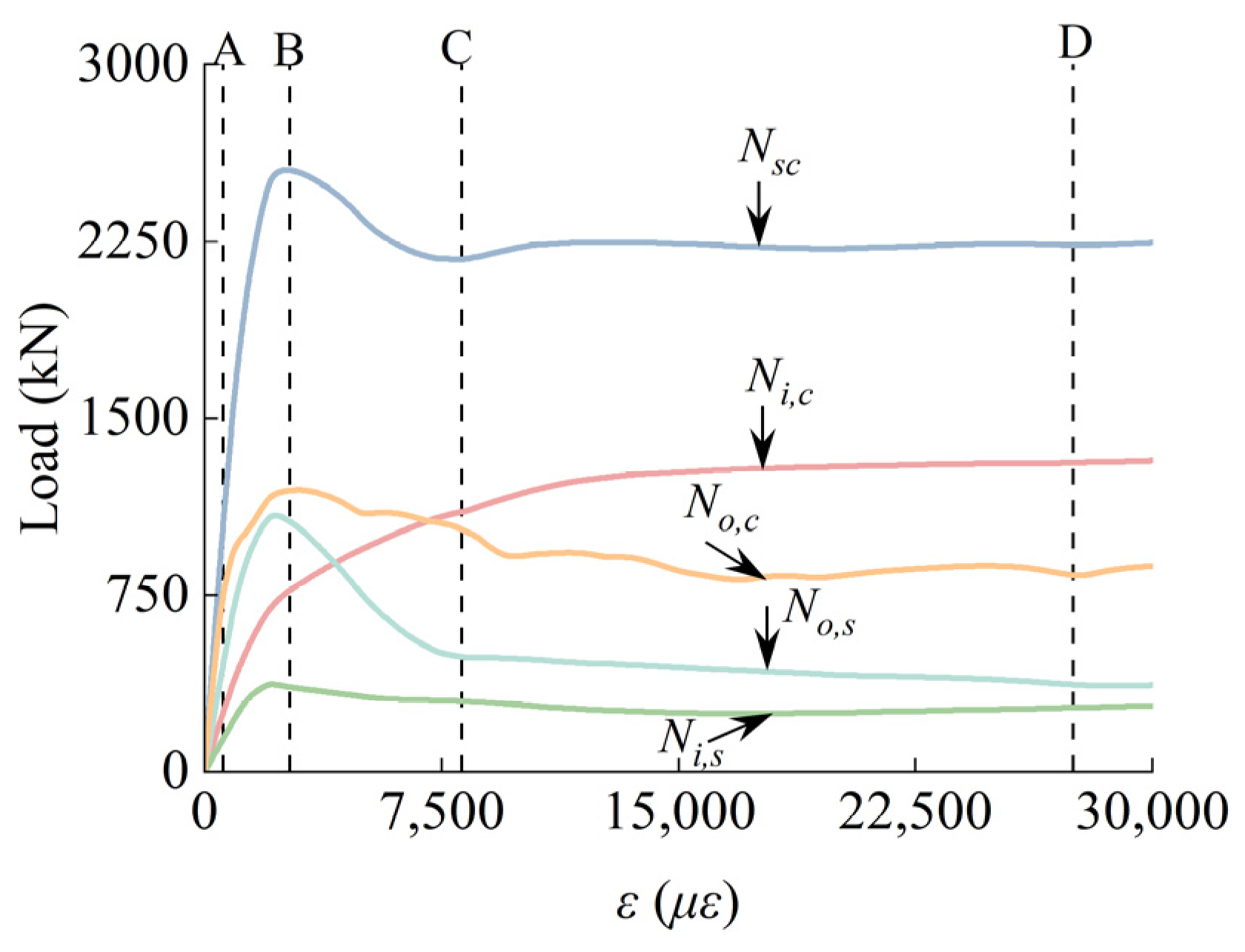
Figure 7 presents the correspondence plot of the average longitudinal stress (σsc) and the average axial strain (εm) for a typical SCGCA-CFDST specimen. The basic parameters of the typical SCGCA-CFDST specimen are as follows: L = 600 mm, D0 = 200 mm, Di = 140.1 mm, t0 = 2.01 mm, ti = 3.78, fyo = 230 MPa, fyi = 322.4 MPa, fco′ = 42.1 Mpa, fci′ = 42.1 MPa. The development of the core coal gangue concrete cross-section’s average longitudinal stress is denoted as σc,i. The square steel tube’s mid-span cross-section exhibits average longitudinal stress, denoted as σs,o. The circular steel tube’s mid-span cross-section experiences average stress, denoted as σs,i. The sandwiched concrete’s mid-span cross-section shows average longitudinal stress (σc,o) in Figure 7. Under compression, the interaction between steel tubes and concrete can be categorized into four distinct stages. (Note: Due to the relatively low load values observed in the steel tubes, the loads applied to the steel tubes in this study have been uniformly amplified by a factor of 10 to facilitate a clearer discernment of the underlying patterns and behaviors.) The bulleted lists look like this below.
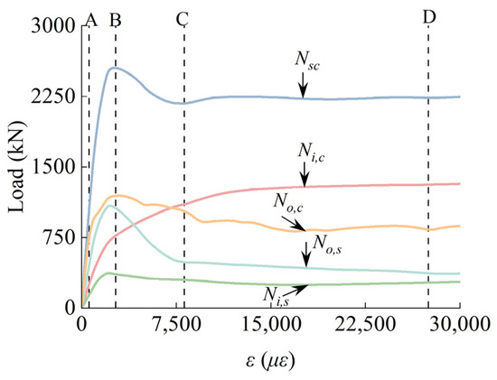
Figure 7.
Load–strain curves of typical SCGCA-CFST specimen.
Phase I (O-A): This phase indicates the elastic stage, where loads acting upon the steel tube and within the concrete show linear progression, signifying the materials’ retention in the elastic state. At this stage, upon reaching an axial strain of about 580με, the stresses within the sandwiched concrete and the core SCG-CAC longitudinally escalate to 0.52fc,o and 0.56fc,i′, respectively.
Phase II (A-B): This phase marks the transition to the elastoplastic stage. As longitudinal loads intensify, plastic deformations commence within the concrete of the SCGCA-CFDST specimens. Upon reaching an axial strain of 2694με, the SCGCA-CFDST specimen attains peak load-bearing capacity. Furthermore, the longitudinal load of the core SCGCAC exhibits nonlinear growth. The sandwiched concrete’s maximum longitudinal load reaches 1089 kN, while the inner and outer steel tubes’ maximum longitudinal loads are 120 kN and 37 kN, respectively.
Phase III (B-C): This phase signifies the descending stage, with point C indicating the trough point on the descending segment of the curve of load–strain. In this phase, the core SCGCAC’s longitudinal load rose by 43%. Consequently, there was a notable reduction (53%) in the strength of the concrete sandwiched due to the buckling of the outer steel tube. Furthermore, the loads between the inner and outer steel tubes also showed a slight downward trend.
Phase IV (C-D): This phase denotes a stabilization stage. Both the SCGCA-CFDST model and the inner steel tube demonstrated stable longitudinal loads. The core SCG-CAC’s longitudinal load escalated by 20%, whereas the longitudinal loads for the sand-witched concrete and outer steel tube exhibited a downward trajectory, with reductions of 22.5% and 14.7%, respectively. Apparently, the confinement offered by the core SCGCAC adequately offsets the strength deterioration of the sandwiched concrete.
3.2. The Pattern of Longitudinal Stress Distribution Within the Concrete During the Loading Process
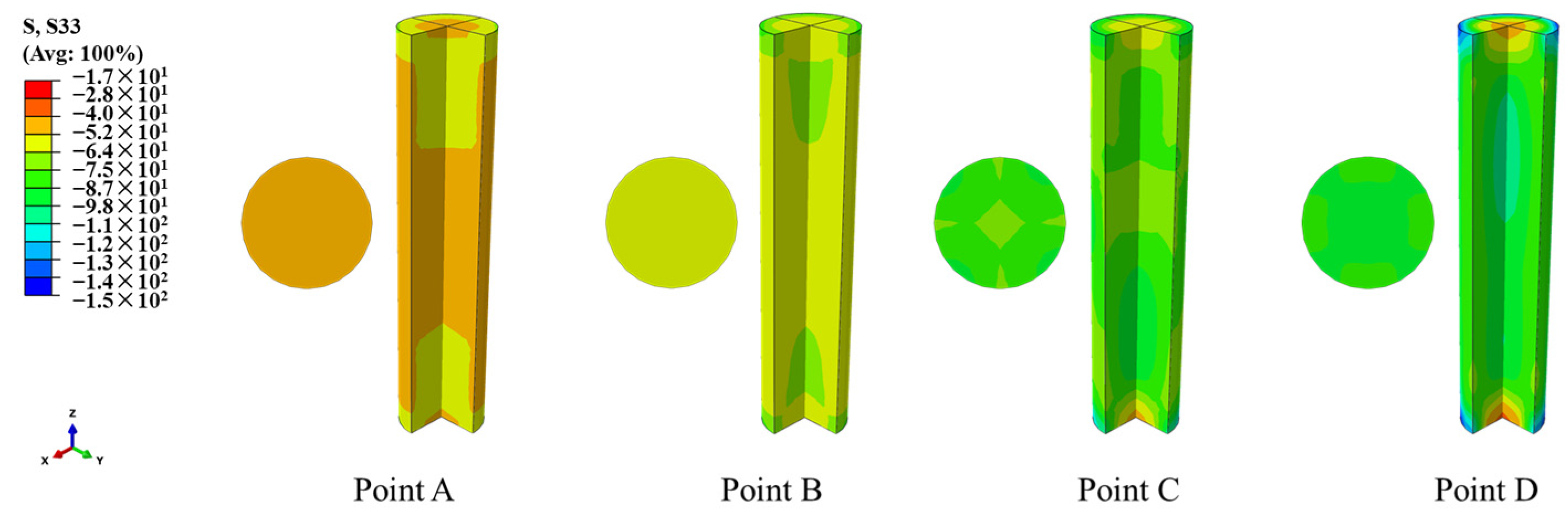
An examination of the distribution of longitudinal stress within the concrete, as illustrated in the four phases depicted in Figure 7, is presented below. As depicted in Figure 8, from point A to point C, the longitudinal stress on the mid-section of the core SCGCAC gradually rose from 52 MPa to 98 MPa, an increase of 88.46%. From points C to D, the stress in the longitudinal direction on the mid-section of the core coal gangue concrete exhibited only a minor change. Throughout the entire loading process, the core SCGCAC’s longitudinal stress showed an upward trend from point A to C, but between points C and D, it tended to stabilize. At point C, the SCGCAC’s core region and the region adjacent to the outer steel tube both showed low stress characteristics. At point D, the mid-section of the core SCGCAC experienced a more uniform stress distribution, due to the concurrent constraining effect applied by both the inner and outer steel tubes.
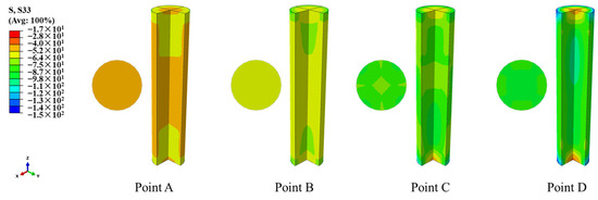
Figure 8.
Longitudinal stress distribution of core SCGCAC.
At point B, as shown in Figure 9, strong confinement is applied to the corners of the concrete that is sandwiched, resulting in a longitudinal stress of 65 MPa. The relative weakness of the confinement applied by the outer steel tube on the sandwiched concrete is attributed to the increased depth of the concrete at the corners. Whereas the confinement in the sandwiched concrete is relatively strong at the thinner divisions, the mean longitudinal stress observed at the midpoint sections of the designated points A, C, and D are all lower than the stress level at B. Consequently, this stress represents the peak value for the sandwiched concrete. At point D, the mid-section of the sandwiched concrete at the thinner region exhibits a distinct characteristic of low stress.
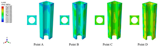
Figure 9.
Longitudinal stress distribution of sandwiched concrete.
3.3. Mises Stress Distribution of Steel Tube
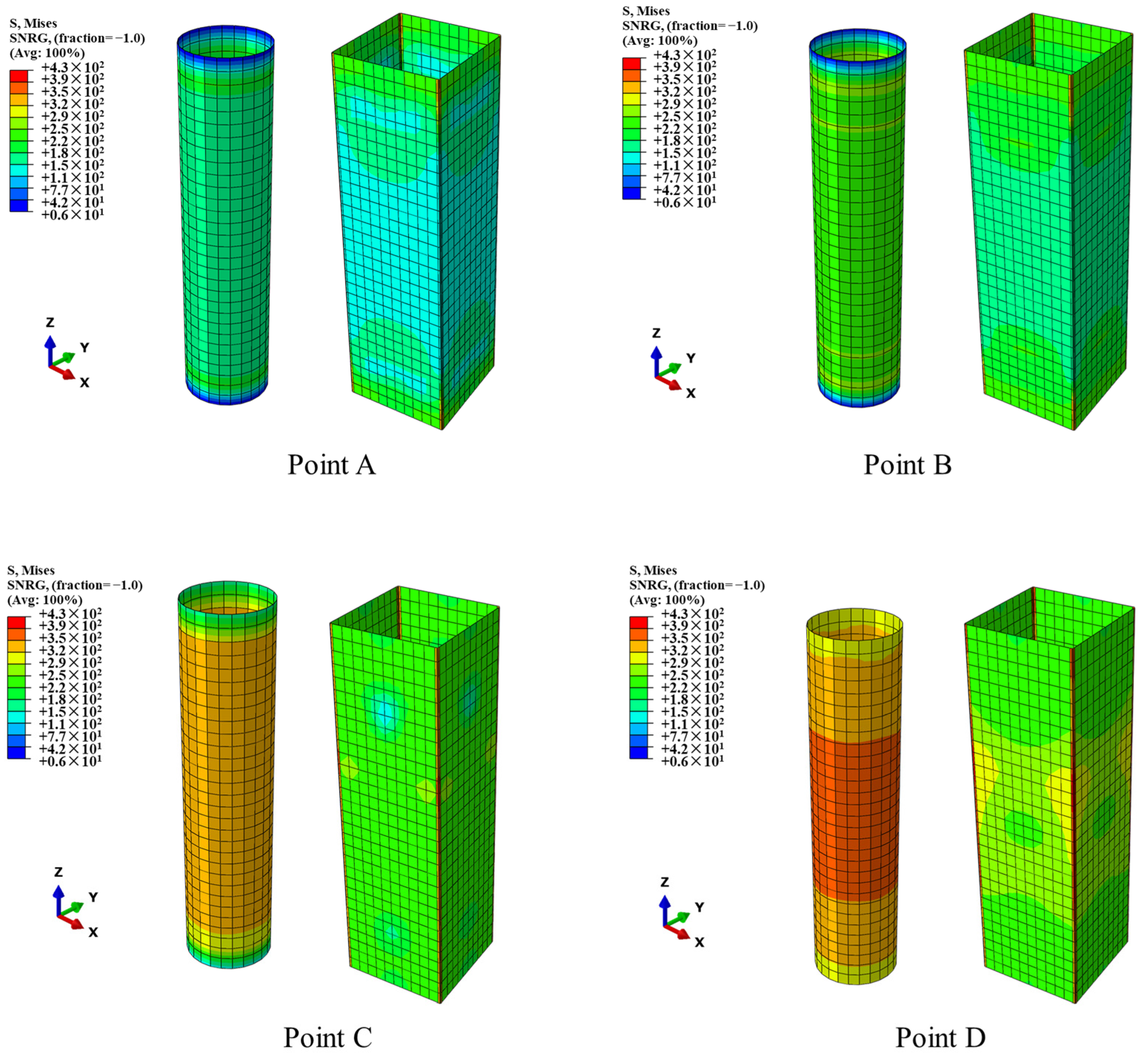
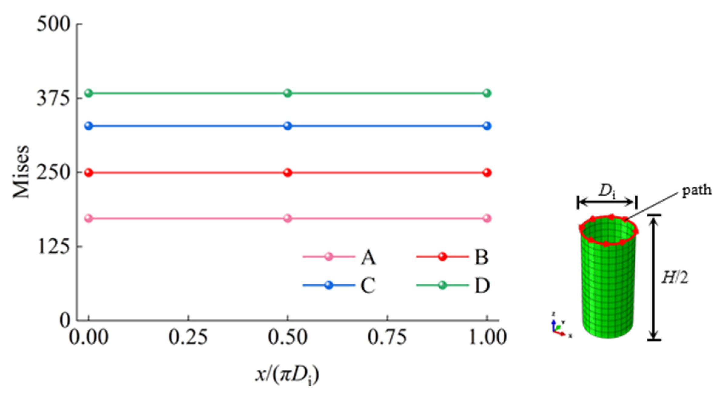
The analysis of the Mises stress distribution, as delineated in the four stages of Figure 7, pertains to the steel tube. The Mises stress within the central section is comparatively higher, decreasing gradually from this point towards the extremities for both the outer and inner steel tubes, as presented in Figure 10 and Figure 11. Figure 11 presents the von Mises stress in the mid-section of the tube’s interior, where the von Mises stress at each point remains stable during the axial compression process. As the longitudinal stress increases between points A and D, the corresponding growth rates are 45%, 31.5%, and 16.9%, respectively, with a decreasing magnitude of increase. In contrast, the mid-section von Mises stress of the outer steel tube progressively increases between points A and D. From Figure 10, it can be observed that the stress distribution at each point on all four sides of outer steel tube is consistent. Therefore, a path along one side of the exterior tube at its mid-section is selected for analysis.

Figure 10.
Mises stress distribution of inner and outer steel tubes.

Figure 11.
Mises stress distribution in the middle section of inner steel tube.
Figure 12 illustrates the pattern of von Mises stress distribution within the central section of the outer tube, indicating that the stress at points A and B is largely consistent. At the peak, affected by corner effects and local buckling, the distribution of stress within the outer steel tube at the corner areas becomes irregular or uneven. Additionally, the corner von Mises stress in the outer steel tube also continues to increase, with respective strengths at each point being 126.76 MPa, 163.94 MPa, 349.20 MPa, and 411.56 MPa. At points C and D, there is no significant change in stress growth at the mid-sections of the outer steel tube, but the von Mises stress at the corners is significantly greater than that in the flat sections.
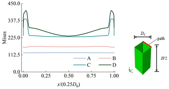
Figure 12.
The outer steel tube’s middle stress distribution.
3.4. Interaction Between Concrete and Steel Tube During Loading Process
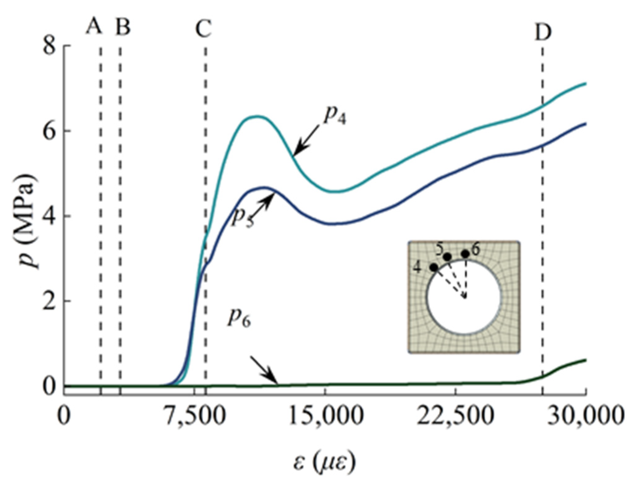
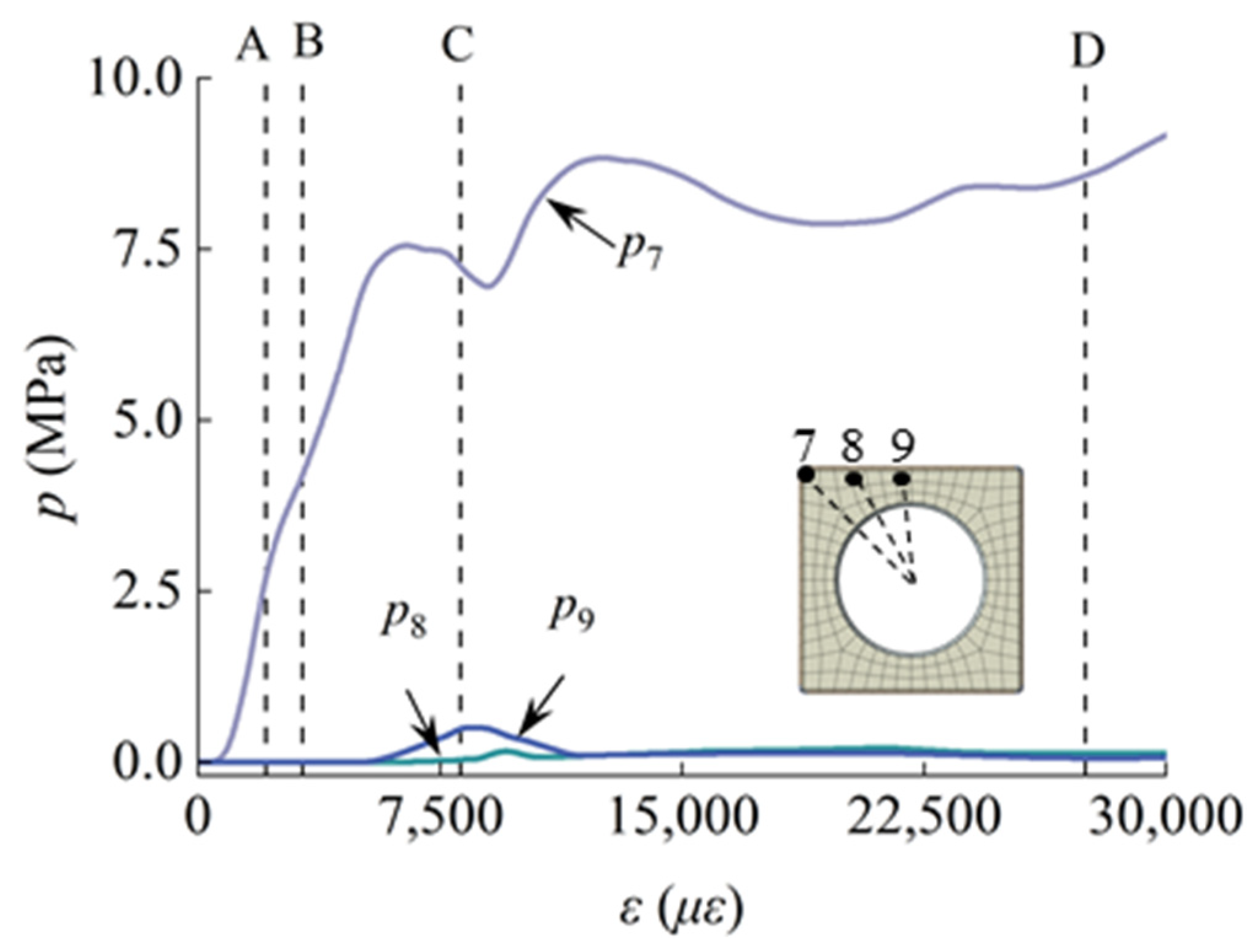
The interaction between the concrete and steel tubes, as represented in the typical model, is analyzed across the four loading stages, as shown in Figure 7. As shown in Figure 13, points 1, 2, and 3 indicate the contact stress at the interface where the inner steel tube meets the core of the SCGCAC. In Figure 14, points 4, 5, and 6 represent the stress levels at the interface where the sandwiched concrete comes into contact with the inner steel tube. In Figure 15, point 7 indicates the stress at the concrete’s corner where contact occurs, while point 9 denotes the stress within the sandwiched concrete at the mid-section position, and point 8 indicates the stress at the concrete interface between points 7 and 9.
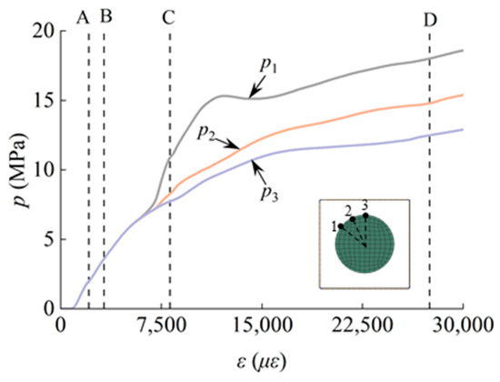
Figure 13.
Mechanical action between inner steel tube and core coal gangue concrete.

Figure 14.
Interaction between inner steel tube and sandwiched concrete.
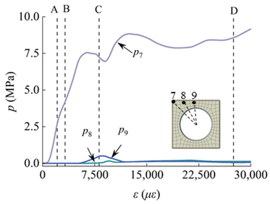
Figure 15.
Interaction between external steel tube and sandwiched concrete.
During the OA stage, the initial contact stress is zero, owing to the steel tube’s Pois-son’s ratio exceeding that of the concrete, followed by a relatively small contact stress.
During the AB stage, contact stress at points 1, 2, 3, and 7 increases rapidly, and this suggests that the inner steel tube enhances the effect of constraint upon the core SCGCAC and also amplifies the confinement at the corners of the outer steel tube’s sandwiched concrete. At points 4, 5, and 6, the contact stress is zero, indicating significant expansion of the sandwiched concrete, which leads to the detachment of the concrete that is sandwiched from the inner steel tube.
During the BC stage, as both the core and sandwiched concretes continue to expand, the contact stress at the interfaces with the inner steel tube for both concretes exhibits a growing trend. The stress at contact points 1, 2, 3, 4, and 5 continues to increase. The rise in contact stress at point 7 signifies a substantial confining effect exerted by the external steel tube on the sandwiched concrete at the corners. The contact stress at points 8 and 9 remains minor, indicating that the buckling deformation of the external steel tube has notably increased, leading to negligible confinement by the external steel tube upon the sandwiched concrete at mid-section.
At points 1, 2, and 3 during the CD stage, the contact stress continues to rise, indicating that the core SCGCAC experiences multiple confinements not only from the sandwiched concrete but also from the outer and inner steel tubes alike. The variation in contact stress at point 7 indicates that the sandwiched concrete is being stabilized by the confining action of the external steel tube. The buckling phenomenon in the external steel tube induces variations in contact stress, and the contact stress at points 8 and 9 remains at 0, indicating debonding has occurred at the boundary where the encased concrete meets the outer steel tube.
4. Prediction of Ultimate Bearing Capacity of SCGCA-CFDST Stub Column
4.1. Parametric Analysis
To enhance the comprehension of the SCGCA-CFDST stub column’s mechanical behavior, a more extensive parametric analysis is required to encompass a broader range of parameters. Parameters impacting the axial compression performance of the SCGCA-CFDST stub column encompass the core SCGCAC strength (fc,i) and sandwiched concrete strength (fc,o), affecting the yield strengths of the external (fy,o) and internal (fy,i) steel tubes, as well as the width-to-thickness ratio (B/to). The diameter-to-thickness ratio (D/ti) of the inner tube and the diameter-to-width ratio (D/B) of the outer tube are also considered important parameters.
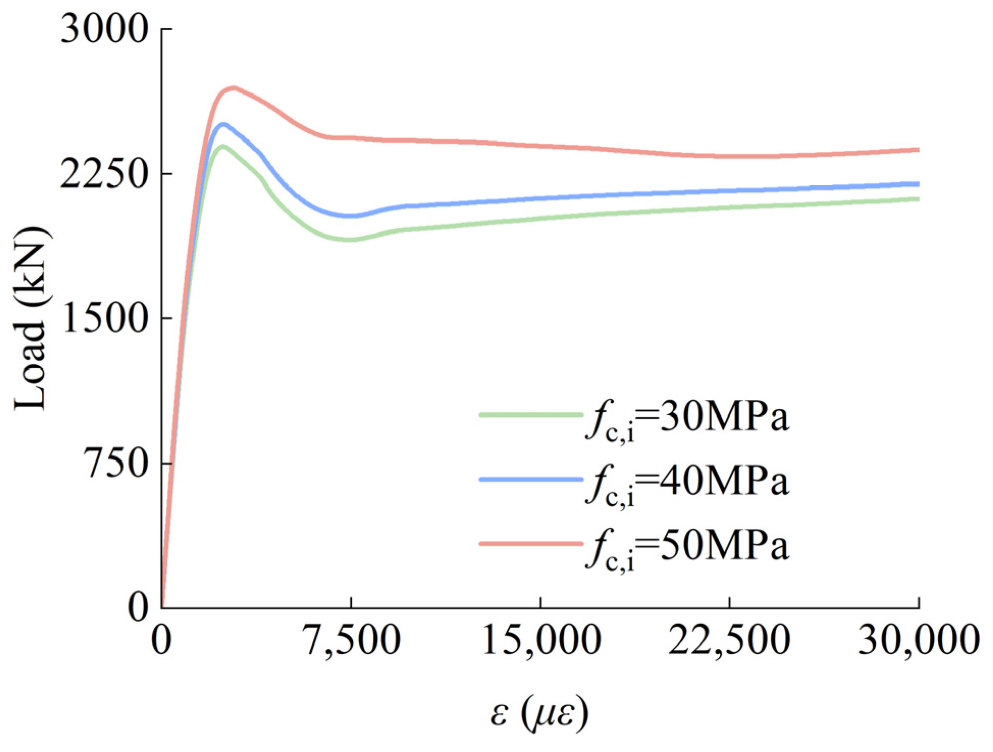
Figure 16 displays the impact of core SCGCAC strength (fc,i) upon the load–strain curves of the square-outside circular-inside (SCGCA-CFDST) stub column. As the strength of fc,i rises from 30 MPa to 50 MPa, marking a 66.67% increase, the structure’s peak load correspondingly increases from 2393.47 kN to 2694.99 kN, reflecting a 12.6% increase. Additionally, fc,i exerts a relatively slight effect on the initial slope of the load–strain curve for the square-outside, circular-inside SCGCA-CFDST stub column. As fc,i increases, both the peak load and its corresponding strain also increase. After reaching the peak, the curve tends to stabilize.
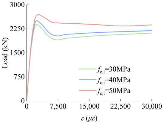
Figure 16.
Effect of strength of different core SCG-CAC on N-ε curve.
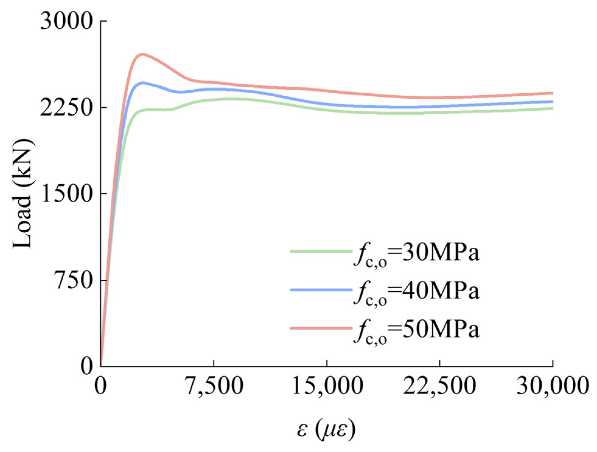
Figure 17 shows how the sandwiched concrete’s strength (fc,o) influences the load–strain curves of the square-outside circular-inside (SCGCA-CFDST) stub column. As fc,o rises from 30 MPa to 50 MPa, marking a 66.67% increase, the structure’s peak load also increases from 2325 kN to 2710.95 kN, reflecting a 16.6% increase. With the increase in fc,o, the peak load’s corresponding strain in the N-ε curve of the SCGCA-CFDST decreases. Additionally, after reaching the peak, the curve shifts from a sustained strengthening phase to a distinct descending phase.
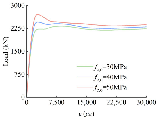
Figure 17.
Effect of different sandwiched concrete strength on N-ε curve.
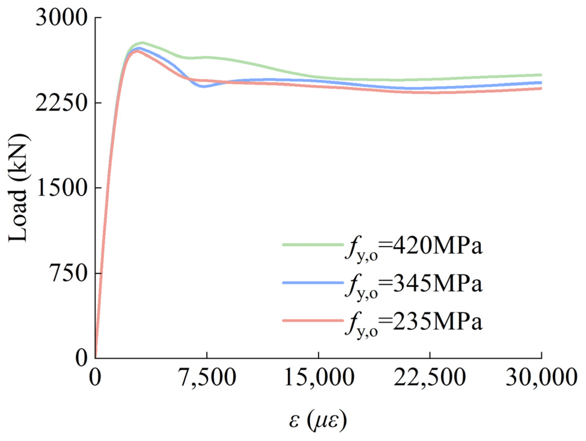
Figure 18 illustrates how the external steel tube’s yield strength (fy,o) impacts the axial load–strain relationship curves of the SCGCA-CFDST stub column. As fy,o increases from 235 MPa to 420 MPa, marking a 78.7% increase, the initial slope and peak load of the SCG-CA-CFDST stub column’s load–strain curve show no significant difference. However, the post-peak phase shows a tendency to become more gradual.
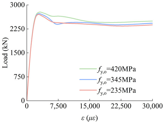
Figure 18.
Effect of different yield strength of outer steel tubes on N-ε curve.
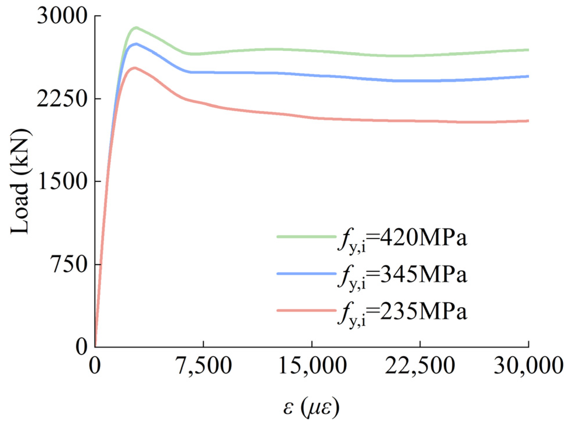
Figure 19 illustrates the influence of the inner steel tube’s yield strength (fy,i) on the axial load–strain relationship curves of the SCGCA-CFDST stub column. As fy,i rises from 235 MPa to 420 MPa, a 78.7% increase, the specimen’s peak load correspondingly increases from 2528.8 kN to 2891.94 kN, representing a 14.36% increase. The inner steel tube’s yield strength (fy,i) exerts a minor influence on the initial slope of the load–strain curves in the axial compression of the SCGCA-CFDST stub column. As fy,i increases, both the peak load and its corresponding strain increase, and the curve tends to stabilize after reaching the peak.
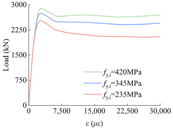
Figure 19.
Effect of different yield strength of inner steel tubes on N-ε curve.
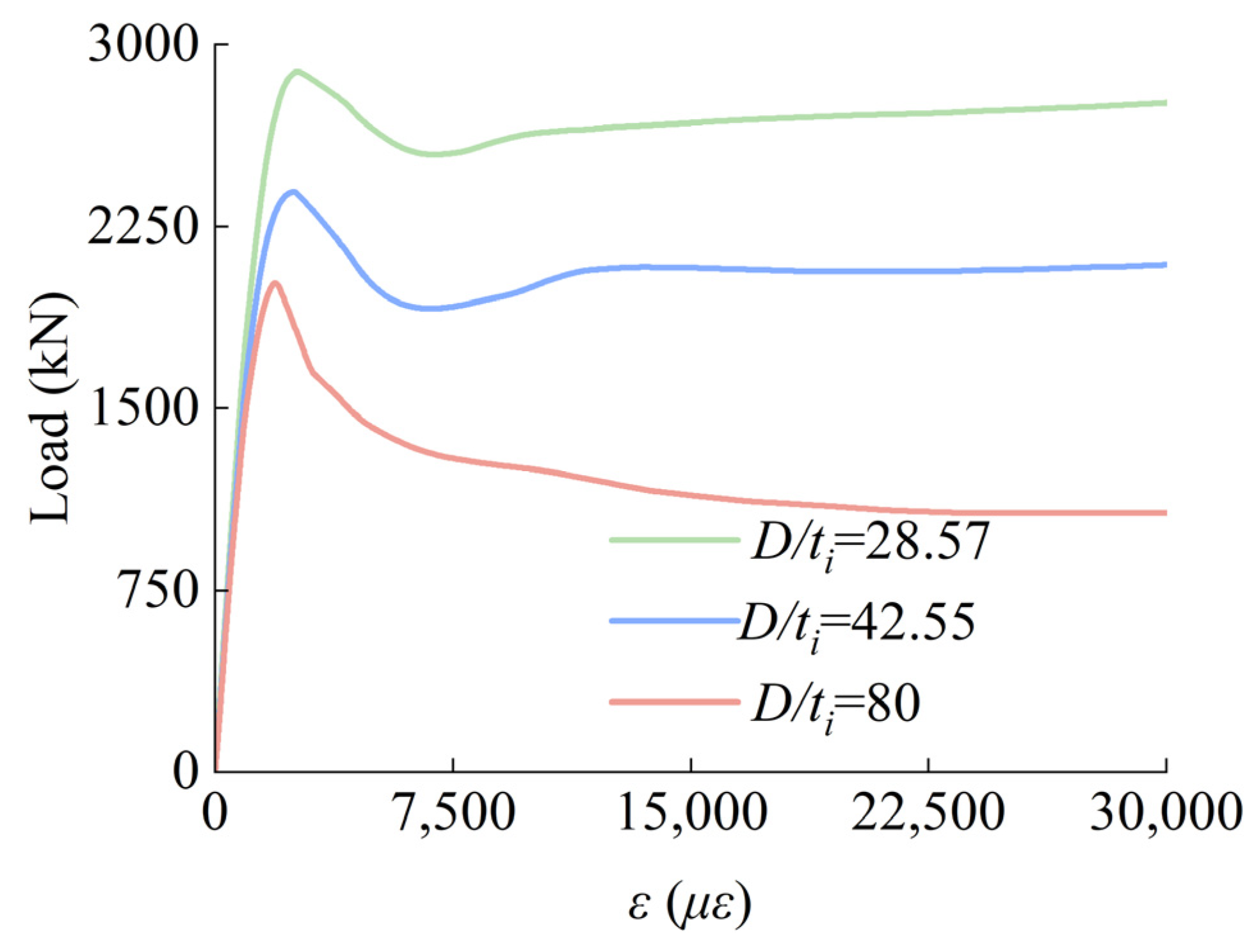
Figure 20 shows the impact of the ratio of the inner steel tube’s diameter to its thickness (D/ti) on the axial compression load–strain curves of the SCGCA-CFDST stub column’s circular steel tube. With an increase in the inner circular steel tube’s diameter-to-thickness ratio (D/ti), the specimens’ peak load increases from 2023.3 kN to 2887.77 kN, marking a 42.72% rise. Consequently, the D/ti ratio of the inner circular steel tube significantly affects the peak load. Upon reaching its peak, the curve shifts from a clear descending phase to a period of stability and then exhibits a minor upward movement.
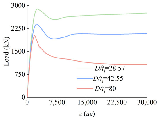
Figure 20.
Effect of different diameter–thickness ratio of inner steel tube on N-ε curve.
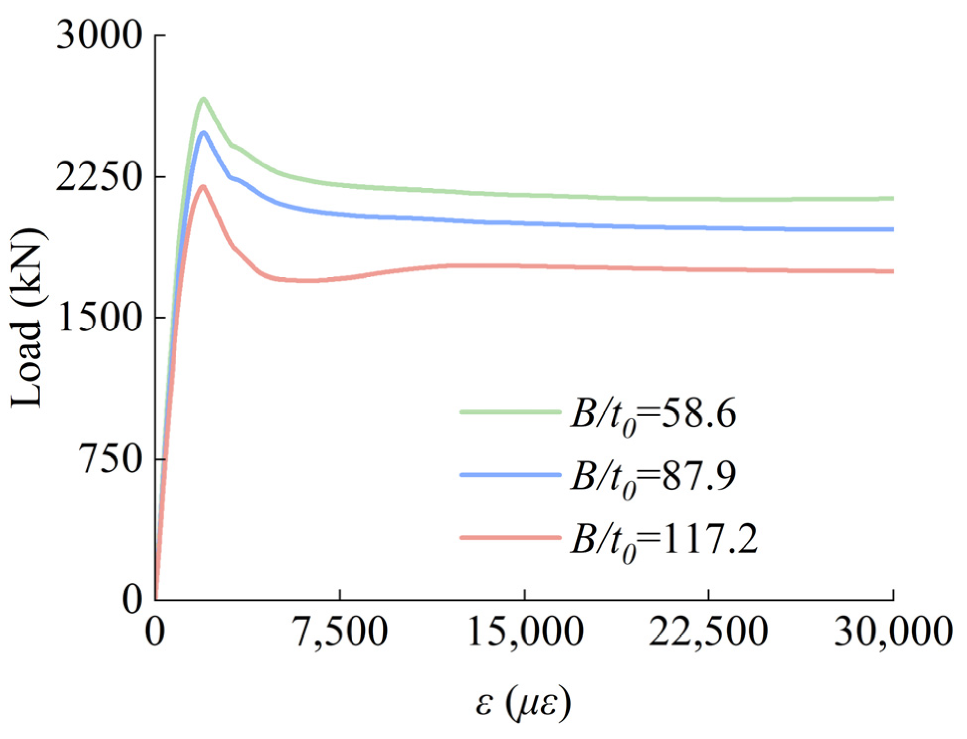
Figure 21 shows how the outer square steel tube’s width-to-thickness ratio (B/to) in-fluences the axial load–strain relationship curves of the SCGCA-CFDST stub column. As the B/to ratio of the outer square steel tube increases, there are no notable variations in the initial slope, peak load, or strain within the load–strain curves of the SCGCA-CFDST stub column. Additionally, as the B/to ratio increases, the load at the stable post-peak stage significantly rises (by 62.52%).
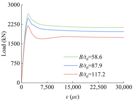
Figure 21.
Effect of different width–thickness ratios of outer steel tubes on N-ε curves.
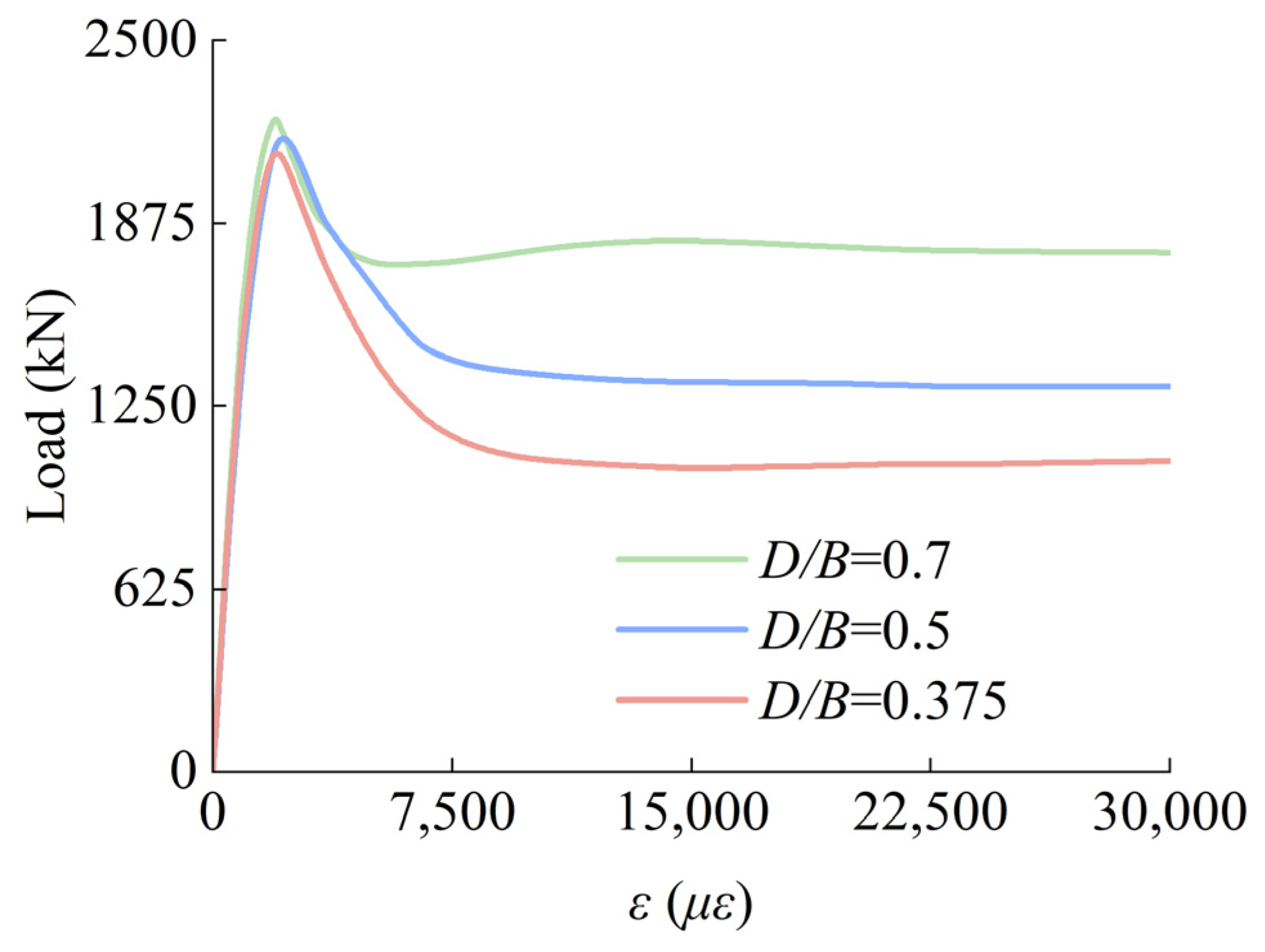
Figure 22 shows how the outer square steel tube’s D/B ratio affects the load–strain curves on the SCGCA-CFDST stub column’s axis. As there is an increase in the outer square steel tube’s D/B ratio, the specimens’ peak load rises from 2120.15 kN to 2230.89 kN, marking a 5.22% increase. The initial slope and peak load displacement of the SCG-CA-CFDST stub columns’ load–strain curves exhibit no significant variation. Post-peak, the curves show a tendency to level off.
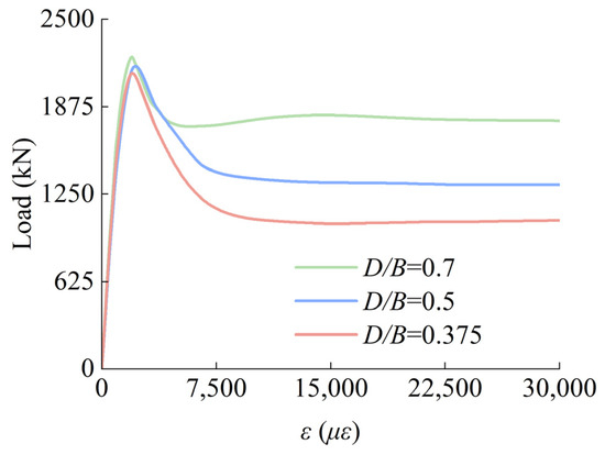
Figure 22.
Effect of different diameter–width ratios of inner and outer steel tubes on N-ε curve.
4.2. Prediction of Ultimate Bearing Capacity
The SCGCA-CFDST stub column’s bearing capacity is determined in this study using Equation (14) from reference [22]. The expression is as follows:
where ks is the strength correction factor, and three correction parameters α, β, and γ are introduced. Aco and Aci indicate the cross-sectional areas for the sandwiched concrete and the core coal SCG-CAC, individually. Aso and Asi represent the cross-sectional areas for the outer and inner steel tubes, individually, and fyo and fyi represent the yield strength of the outer and inner steel tubes, individually. The compressive strengths of the sandwiched concrete and the core SCG-CAC, in cylindrical form, are represented by fco′ and fci′, individually. ξo represents the confinement coefficient for the sandwiched concrete, as detailed below:
where D0 and t0 denote the dimensions of the external steel tube—specifically, its side length and thickness—while Ac,nominal refers to the cross-sectional area enclosed by the external steel tube.
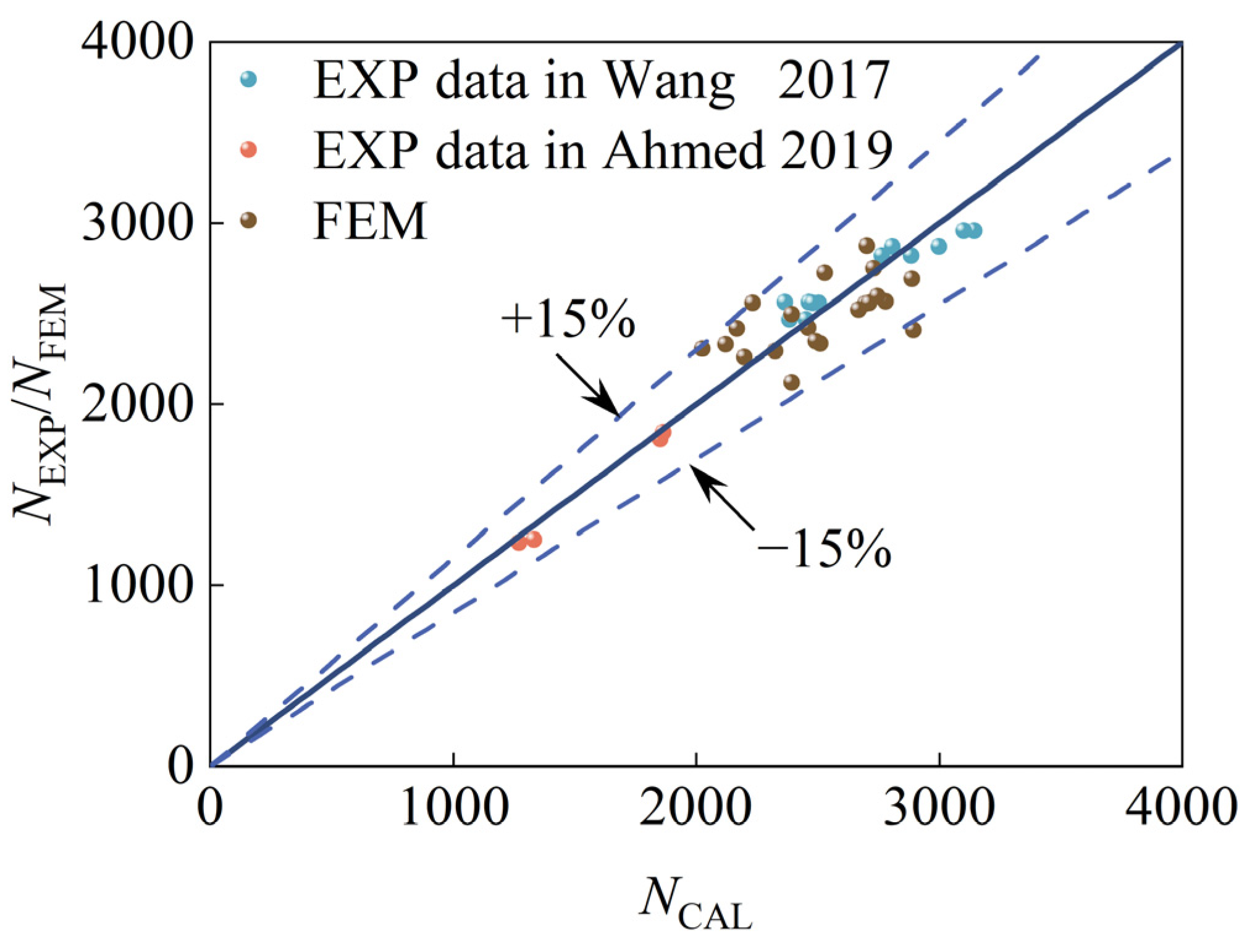
Figure 23 presents a comparison among the experimental data (NEXP), finite element analysis outcomes (NFEM), and the theoretical predictions (NCAL) derived from Equation (14) for SCGCA-CFDST stub columns. As observed in the figure, the errors are all within 15%, with the minimum error being 0.80%, the average absolute error being 5.79%, and the standard deviation being 0.073. The aforementioned predictive equation can precisely determine the maximum load-bearing capacity of the square-outside circular-inside SCGCA-CFDST stub columns.
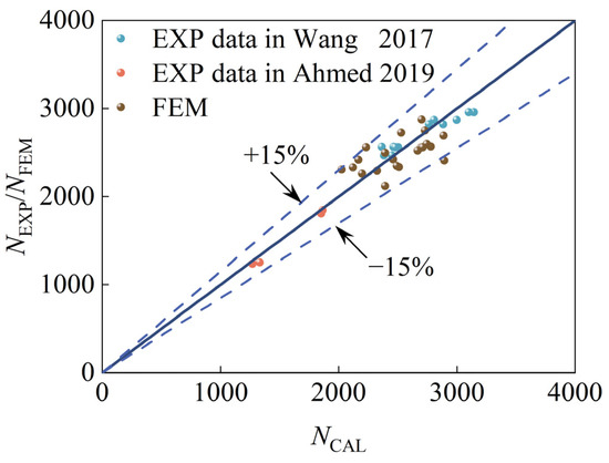
Figure 23.
Comparison of predicted results with experimental and finite element results in [20,21].
5. Conclusions
- (1)
- Utilizing the constitutive relationship of core concrete made with coarse aggregate derived from spontaneously combusted coal gangue, a finite element analysis model for SCGCA-CFDST stub columns was created. The model was validated against the existing literature, achieving an average absolute error of 2.21%. The average value (μ) and standard deviation (SD) of NFEM/NEXP were 0.99 and 0.061, individually. The outcomes demonstrate the precision of the finite element model presented in this research for predicting the mechanical performance of SCGCA-CFDST stub columns.
- (2)
- Analysis of the typical SCGCA-CFDST stub column’s loading process found that both the outer and inner steel tubes reach the yield state nearly simultaneously. The core SCGCAC’s interaction is significantly higher than that of the sandwiched concrete due to dual-layer confinement from the steel tubes. The outer steel tube enhances the sandwiched concrete’s strength by 3.56 times, less than the 5.41-times increase for the core SCGCAC by the inner steel tube. This suggests that SCGCAC in the core of CFDST offers superior confinement, benefiting engineering applications.
- (3)
- Parametric analysis identified fc,i, fc,o, fy,i, B/to, and D/ti as key factors affecting the SCGCA-CFDST stub column’s load-bearing capacity, with fy,o and D/B having a minor impact. The inner tube’s thickness most significantly influences the load-bearing capacity, increasing it by 42.72%. Finite element analysis validated a formula for calculating the ultimate load-bearing capacity, proving its suitability for predicting SCGCA-CFDST stub columns’ strength.
Author Contributions
Conceptualization, J.W.; methodology, J.W.; software, C.W.; validation, Z.G. and C.W.; writing—original draft preparation, J.W.; writing—review and editing, W.W.; visualization, H.W.; supervision, Z.H.; funding acquisition, W.W. All authors have read and agreed to the published version of the manuscript.
Funding
This research was funded by “the (Key) Project of Department of Education of Guangdong Province, grant number 2024KCXTD068” and “Characteristic Innovation Project of Department of Education of Guangdong Province, grant number 2023KTSCX218”.
Data Availability Statement
The data presented in this study are available on request from the corresponding author.
Conflicts of Interest
The authors declare no conflicts of interest.
Nomenclature
| Aco | Cross-sectional areas for the sandwiched concrete |
| Aci | Cross-Sectional Areas For The Core Coal SCG-CAC |
| Aso | Cross-Sectional Areas For The Outer Steel Tubes |
| Asi | Cross-Sectional Areas For The Outer Inner Tubes |
| Do | All Indicate The Side Length Of The Outer Steel Pipe |
| Di | All Indicate The Side Length Of The Inner Steel Pipe |
| Et | Modulus Of Elasticity Of Steel |
| Ec | Modulus Of Elasticity Of Concrete |
| Compressive Strength Of Concrete Cylinders | |
| Strain | |
| εc0 | Peak Strain Of Unconfined Concrete |
| εcc | Peak Strain Of Confined Concrete |
| Stress | |
| fB | The Confining Pressure Value At Point B |
| fr | Residual Stress |
| fyi | Inner Steel Pipe Yield Strength |
| fyo | Yield Strength Of Outer Steel Pipes |
| ftu | The ultimate tensile strength of the steel tube |
| ti | Inner Steel Pipe Wall Thickness |
| to | The Wall Thickness Of The Outer Steel Pipe |
| Peak Load From The Test | |
| Peak Loads Derived From Finite Element Model | |
| Ac,nominal | Cross-sectional area enclosed by the external steel tube |
| ξo | Constraint Factor |
References
- Jabłońska, B.; Kityk, A.V.; Busch, M.; Huber, P. The Structural and Surface Properties of Natural and Modified Coal Gangue. J. Environ. Manag. 2017, 190, 80–90. [Google Scholar] [CrossRef]
- Li, J.; Wang, J. Comprehensive Utilization and Environmental Risks of Coal Gangue: A Review. J. Clean. Prod. 2019, 239, 117946. [Google Scholar] [CrossRef]
- Cheng, Y.; Hongqiang, M.; Hongyu, C.; Jiaxin, W.; Jing, S.; Zonghui, L.; Mingkai, Y. Preparation and Characterization of Coal Gangue Geopolymers. Constr. Build. Mater. 2018, 187, 318–326. [Google Scholar] [CrossRef]
- Wang, G.; Wei, Y.; Miao, K.; Zheng, K.; Dong, F. Axial Compressive Behavior of Seawater Sea-Sand Coral Aggregate Concrete-Filled Circular FRP-Steel Composite Tube Columns. Constr. Build. Mater. 2022, 315, 125737. [Google Scholar] [CrossRef]
- Zhou, M.; Dou, Y.; Zhang, Y.; Zhang, Y.; Zhang, B. Effects of the Variety and Content of Coal Gangue Coarse Aggregate on the Mechanical Properties of Concrete. Constr. Build. Mater. 2019, 220, 386–395. [Google Scholar] [CrossRef]
- Wang, Q.; Li, Z.; Zhang, Y.; Zhang, H.; Zhou, M.; Fang, Y. Influence of Coarse Coal Gangue Aggregates on Elastic Modulus and Drying Shrinkage Behaviour of Concrete. J. Build. Eng. 2020, 32, 101748. [Google Scholar] [CrossRef]
- Gao, S.; Zhao, G.; Guo, L.; Zhou, L.; Yuan, K. Utilization of Coal Gangue as Coarse Aggregates in Structural Concrete. Constr. Build. Mater. 2021, 268, 121212. [Google Scholar] [CrossRef]
- Qiu, J.; Zhu, M.; Zhou, Y.; Guan, X. Effect and Mechanism of Coal Gangue Concrete Modification by Fly Ash. Constr. Build. Mater. 2021, 294, 123563. [Google Scholar] [CrossRef]
- Zhang, Y.; Wang, Q.; Zhou, M.; Fang, Y.; Zhang, Z. Mechanical Properties of Concrete with Coarse Spontaneous Combustion Gangue Aggregate (SCGA): Experimental Investigation and Prediction Methodology. Constr. Build. Mater. 2020, 255, 119337. [Google Scholar] [CrossRef]
- Zhang, T.; Zhu, Q.; Liu, H.; Gao, S. Utilization of Coal Gangue Sand in Structural Concrete as Fine Aggregate towards Sustainable Production. Constr. Build. Mater. 2024, 417, 135264. [Google Scholar] [CrossRef]
- Zhang, Y.; Xu, Q.; Wang, Q.; Zhou, M.; Liu, H.; Guo, H. Axial Compressive Behavior of Circular Concrete-Filled Steel Tube Stub Columns Prepared with Spontaneous-Combustion Coal Gangue Aggregate. J. Build. Eng. 2022, 48, 103987. [Google Scholar] [CrossRef]
- Zhang, N.; Zhao, Z.; Zheng, C. Compression Behavior of GFRP–Coal Gangue Concrete–Steel Tubular Columns. Int. J. Press. Vessels Pip. 2022, 197, 104650. [Google Scholar] [CrossRef]
- Xu, Q.; Zhang, Y.; Liu, H.; Zhou, M.; Wang, Q.; Lin, H. Effect of Spontaneous-Combustion Coal Gangue Aggregate on Axial Performance of Square Concrete-Filled Steel Tube Stub Columns. Structures 2022, 44, 216–235. [Google Scholar] [CrossRef]
- Wang, J.; Chen, J.; Liu, M. Theoretical Model for Spontaneous Combustion Gangue Coarse Aggregate Concrete Filled Steel Tube Stub Columns. J. Constr. Steel Res. 2024, 213, 108353. [Google Scholar] [CrossRef]
- Ci, J.; Ahmed, M.; Tran, V.-L.; Jia, H.; Chen, S. Axial Compressive Behavior of Circular Concrete-Filled Double Steel Tubular Short Columns. Adv. Struct. Eng. 2022, 25, 259–276. [Google Scholar] [CrossRef]
- Hassanein, M.F.; Silvestre, N.; Yan, X.-F. Confinement-Based Direct Design of Circular Concrete-Filled Double-Skin Normal and High Strength Steel Short Columns. Thin-Walled Struct. 2023, 183, 110446. [Google Scholar] [CrossRef]
- Ahmed, M.; Gohari, S.; Sennah, K.; Chen, W.; Liang, Q.Q. Computational Simulation of Nonlinear Inelastic Behavior of Circular Concrete-Filled Stainless-Steel Tubular Short Columns Incorporating Confinement Effects. Eng. Struct. 2023, 274, 115183. [Google Scholar] [CrossRef]
- Yan, X.; Ahmed, M.; Hassanein, M.F.; He, M. Performance Analysis and Design of Circular High-strength Concrete-filled Double-skin Aluminum Tubular Short Columns under Axial Loading. Struct. Concr. 2023, 24, 5677–5696. [Google Scholar] [CrossRef]
- Lin, C.; Zhou, J. Unified Compressive Strength Model for Axially Loaded Circular Composite Short Columns. J. Constr. Steel Res. 2023, 203, 107840. [Google Scholar] [CrossRef]
- Wang, Z.-B.; Tao, Z.; Yu, Q. Axial Compressive Behaviour of Concrete-Filled Double-Tube Stub Columns with Stiffeners. Thin-Walled Struct. 2017, 120, 91–104. [Google Scholar] [CrossRef]
- Ahmed, M.; Liang, Q.Q.; Patel, V.I.; Hadi, M.N.S. Experimental and Numerical Studies of Square Concrete-Filled Double Steel Tubular Short Columns under Eccentric Loading. Eng. Struct. 2019, 197, 109419. [Google Scholar] [CrossRef]
- Zheng, Y.; Tao, Z. Compressive Strength and Stiffness of Concrete-Filled Double-Tube Columns. Thin-Walled Struct. 2019, 134, 174–188. [Google Scholar] [CrossRef]
- Ci, J.; Chen, S.; Jia, H.; Yan, W.; Song, T.; Kim, K.-S. Axial Compression Performance Analysis and Bearing Capacity Calculation on Square Concrete-Filled Double-Tube Short Columns. Mar. Struct. 2020, 72, 102775. [Google Scholar] [CrossRef]
- Liang, Q.Q.; Fragomeni, S. Nonlinear Analysis of Circular Concrete-Filled Steel Tubular Short Columns under Axial Loading. J. Constr. Steel Res. 2009, 65, 2186–2196. [Google Scholar] [CrossRef]
- Samani, A.K.; Attard, M.M. A Stress–Strain Model for Uniaxial and Confined Concrete under Compression. Eng. Struct. 2012, 41, 335–349. [Google Scholar] [CrossRef]
- Binici, B. An Analytical Model for Stress–Strain Behavior of Confined Concrete. Eng. Struct. 2005, 27, 1040–1051. [Google Scholar] [CrossRef]
- Han, L.-H.; Li, W.; Bjorhovde, R. Developments and Advanced Applications of Concrete-Filled Steel Tubular (CFST) Structures: Members. J. Constr. Steel Res. 2014, 100, 211–228. [Google Scholar] [CrossRef]
- Han, L.-H.; Yao, G.-H.; Tao, Z. Performance of Concrete-Filled Thin-Walled Steel Tubes under Pure Torsion. Thin-Walled Struct. 2007, 45, 24–36. [Google Scholar] [CrossRef]
- Elchalakani, M.; Zhao, X.-L.; Grzebieta, R. Tests on Concrete Filled Double-Skin (CHS Outer and SHS Inner) Composite Short Columns under Axial Compression. Thin-Walled Struct. 2002, 40, 415–441. [Google Scholar] [CrossRef]
- Abdel-Rahman, N.; Sivakumaran, K.S. Material Properties Models for Analysis of Cold-Formed Steel Members. J. Struct. Eng. 1997, 123, 1135–1143. [Google Scholar] [CrossRef]
- Liang, H.; Li, W.; Huang, Y.; Lu, Y. Axial Behaviour of CFST Stub Columns Strengthened with Steel Tube and Sandwiched Concrete Jackets. Thin-Walled Struct. 2020, 155, 106942. [Google Scholar] [CrossRef]
- Zhu, Y.; Yang, H.; Gardner, L.; Wan, J. Performance of Reinforced Concrete-Filled Steel Tubular (RCFST) Members Subjected to Transverse Impact Loading. J. Constr. Steel Res. 2022, 188, 107018. [Google Scholar] [CrossRef]
- Qian, J.; Li, N.; Ji, X.; Zhao, Z. Experimental Study on the Seismic Behavior of High Strength Concrete Filled Double-Tube Columns. Earthq. Eng. Eng. Vib. 2014, 13, 47–57. [Google Scholar] [CrossRef]
- Han, L.-H.; He, S.-H.; Liao, F.-Y. Performance and Calculations of Concrete Filled Steel Tubes (CFST) under Axial Tension. J. Constr. Steel Res. 2011, 67, 1699–1709. [Google Scholar] [CrossRef]
- Tao, Z.; Wang, Z.-B.; Yu, Q. Finite Element Modelling of Concrete-Filled Steel Stub Columns under Axial Compression. J. Constr. Steel Res. 2013, 89, 121–131. [Google Scholar] [CrossRef]
- Chen, J.-Y.; Li, W.; Han, L.-H.; Wang, F.-C.; Mu, T.-M. Structural Behaviour of Concrete-Encased CFST Box Stub Columns under Axial Compression. J. Constr. Steel Res. 2019, 158, 248–262. [Google Scholar] [CrossRef]


Disclaimer/Publisher’s Note: The statements, opinions and data contained in all publications are solely those of the individual author(s) and contributor(s) and not of MDPI and/or the editor(s). MDPI and/or the editor(s) disclaim responsibility for any injury to people or property resulting from any ideas, methods, instructions or products referred to in the content. |
© 2024 by the authors. Licensee MDPI, Basel, Switzerland. This article is an open access article distributed under the terms and conditions of the Creative Commons Attribution (CC BY) license (https://creativecommons.org/licenses/by/4.0/).