Article

Research on the Reinforcement Effect and Bearing Characteristics of High-Pressure Jet-Grouting Piles on Covered Road Composite Ground in Landfill Sites

1
Beijing Key Laboratory of Urban Underground Space Engineering, School of Civil and Resources Engineering, University of Science and Technology Beijing, Beijing 100083, China
2
Shanghai Tunnel Engineering Rail Transit Design and Research Institute, Shanghai 200030, China
3
China Railway Second Bureau Fifth Engineering Co., Ltd., Chengdu 610091, China
*
Author to whom correspondence should be addressed.
Buildings 2024, 14(2), 444; https://doi.org/10.3390/buildings14020444
Submission received: 30 December 2023 / Revised: 19 January 2024 / Accepted: 28 January 2024 / Published: 6 February 2024
(This article belongs to the Special Issue Seismic Response Analysis of Underground Structure)

Abstract

:
There is a notable difference between garbage pile foundations and general site foundations; due to their uneven particles, complex structure, and diverse composition, there are relatively few cases that can be used for reference. In this study, with the aim of renovating a landfill in Shenzhen, bearing-layer reinforcements were introduced in the overlying road of a garbage heap dominated by construction waste. The bearing capacity of a single-pile composite foundation was studied through a core-pulling test of high-pressure jet-grouting piles, a static load test of the bearing capacity of the single-pile composite foundation, design estimation, and numerical analysis. The results show that the obtained eigenvalue of the design estimate was 267.8 kPa, and the eigenvalue of the field test was between 182.58 kPa and 196.89 kPa, meeting the design requirement of an eigenvalue of no less than 175 kPa. The bearing capacity of the composite foundation of the single jet-grouting pile was analyzed using the ABAQUS numerical simulation software; the characteristic value of the bearing capacity of the single-pile composite foundation was 186.01 kPa, and the variation trend of its settlement–load curve was the same as that of the field test results, which met the design requirements. High-pressure jet-grouting pile technology has achieved remarkable results in the reinforcement of foundations that are mainly composed of construction waste.

1. Introduction

The rapid improvement in China’s urbanization level has been accompanied by a sharp increase in urban waste, which necessitates stricter requirements for the treatment capacity of landfills [1,2]. In order to improve this capacity, scholars have tried to renovate original landfills, including improving their roads, drainage systems, and lighting systems [3,4]. In addition, engineering construction will be carried out above original landfill sites to improve their treatment capacity and the utilization rate of land resources [5,6,7].
Underground geotechnical stratification is determined using borehole-coring technology. Garbage dumps with poor mechanical properties, low shear strength, high compressibility, a certain corrosiveness, and a weak bearing capacity are not suitable for engineering construction [8,9,10]. High-pressure jet-grouting pile technology is a common method for the treatment of soft-soil foundations; a drilling machine is used to carry out a pilot operation for each pile, with the hole drilled to a specified depth to ensure that the pile length meets the design requirements. Then, a jet-grouting pile pipe is inserted to a predetermined depth, high-pressure jet grouting is carried out, and cement mortar is mixed with the surrounding soil and solidified to form a uniform solid cylinder, which can effectively strengthen the soil and has a certain anti-seepage reinforcement effect. This method is now widely used in the reinforcement of various soft-soil foundations [11,12,13]. Wei et al. [14] argued that, on the Yangtze River embankment outside the Yangtze River construction site, it is easy for embankment soil slippage or even collapse to occur. In their study, high-pressure jet grouting was used to strengthen soil to improve its anti-slip stability and anti-overturning stability, as well as the overall stability of the embankment. After testing the reinforcement, the vertical displacement of the embankment’s daily variation was less than 5 mm and the cumulative displacement was less than 60 mm, within the allowable range. Ho et al. [15] used high-pressure jet-grouting pile technology to strengthen soil in order to minimize disturbance to the surrounding ground during a basement excavation project, and the movement of the inner wall in the place where the jet-grouting pile was used was limited to 11.2 mm, when previously, it was 38.4 mm. Qiu et al. [16] studied the settlement performance of a three-lane tunnel with a large cross-section in Gansu Province after the use of high-pressure jet-grouting piles. After conducting finite element analysis and a field investigation, the consolidation settlement was calculated to be 14.99 mm; the on-site observation was 12.89 mm; the settlement around the tunnel and the overall consolidation settlement decreased evenly; the high-pressure jet-grouting pile technology had a strong reinforcement effect. Li et al. [17] studied the reinforcement effect of high-pressure jet-grouting piles on the collapsible foundations of deep loess tunnels, and used on-site monitoring methods to monitor the settlement performance of the tunnel foundation, additional stress, earth stress, rock pressure, etc. They found that the stress at the top of the pile and the earth pressure between the piles increased rapidly in the first 45 days, and the stress tended to be stable after 45 days. The stress increased with increasing distance from the tunnel centerline, and the settlement of the tunnel foundation gradually increased with the passage of time, becoming stable after 50 days of construction. Li et al. [13] studied the performance of grouting materials and consolidated bodies of high-pressure jet-grouting piles, as well as the on-site reinforcement effect. Their results showed that the compressive strength, elastic modulus, and impermeability of the consolidated bodies were related to the water–cement ratio, and the strength increased with increasing cement content. When an ultra-shallow buried tunnel was excavated, after the reinforcement of the high-pressure jet-grouting pile, the surrounding rock at the top was more stable, the surrounding rock cracks were consolidated and filled with cement soil, and the integrity improved. Li et al. [18] systematically evaluated the adaptability of jet-grouting composite foundations in shallow collapsible loess tunnels. Taking a tunnel with a buried depth of 20 m as an example, they studied the deformation control of the foundation during construction and the control of the foundation’s settlement after construction; the results showed that the uplift displacement of the pile could be controlled by changing the pile length and improving the replacement rate, and a combination of long and short piles could reduce the low-level uneven settlement and plastic zone. Fan et al. [11] used high-pressure jet-grouting piles to strengthen a tunnel’s foundations, which had been weakened by gradual sinking of the lining of the tunnel due to long-term operations. After reinforcement, the strength of the foundation was significantly improved and the cumulative settlement reduction was greater than 75%; the reinforcement better controlled the deformation of the tunnel’s bottom and was conducive to improving the stability of the tunnel’s foundation. Dong et al. [19], focusing on a real case of highway damage in Shanxi, studied the influence of jet-grouting piles either penetrating or not penetrating loess on the uneven settlement of the highway subgrade in a loess area, and the results showed that the lateral friction resistance of the jet-grouting pile penetrating the loess was small; the foundation settlement quickly reached a stable state when the underlying soft layer was thicker, and the foundation settlement increased with time when the underlying loess was deeper. Zhang Y et al. [20] used empirical formulas, numerical simulations, statistical analysis, and artificial intelligence techniques to comprehensively discuss various techniques for the evaluation and design of stabilized ore pillars. Combining AI with finite and discrete element simulations can not only improve the safety and environmental sustainability of resource extraction, but can also generate significant economic benefits. Overall, the application of high-pressure jet-grouting pile technology for the reinforcement of soft-soil foundations is common, but its application to the foundations of garbage heaps is relatively rare.
Based on a foundation reinforcement project on a new road section of a landfill in Shenzhen, this paper studies the application of high-pressure jet-grouting pile technology to strengthen the foundation of a garbage heap dominated by construction waste. The composite bearing capacity of a single pile was studied using a combination of design estimation, pile test experiments, and ABAQUS numerical simulation analysis, and the optimal construction parameters were determined based on the bearing capacity of a single-pile composite foundation that met the design requirements and was applied to the construction process [21,22,23]. There are many types of construction waste, such as concrete blocks, bricks, and gravel blocks in the foundation of new road sections. Additionally, the lower layer of construction waste is an argillaceous siltstone layer, and the stratum has the characteristics of considerable thickness, a complex structure, and inconsistent compaction; therefore, it cannot be directly used as the bearing layer of a road foundation [24,25,26]. Through this research on foundation reinforcement for construction waste heaps, we hope to provide a reference for the design and construction of high-pressure jet-grouting pile technology to strengthen the foundations of miscellaneous construction waste fill.

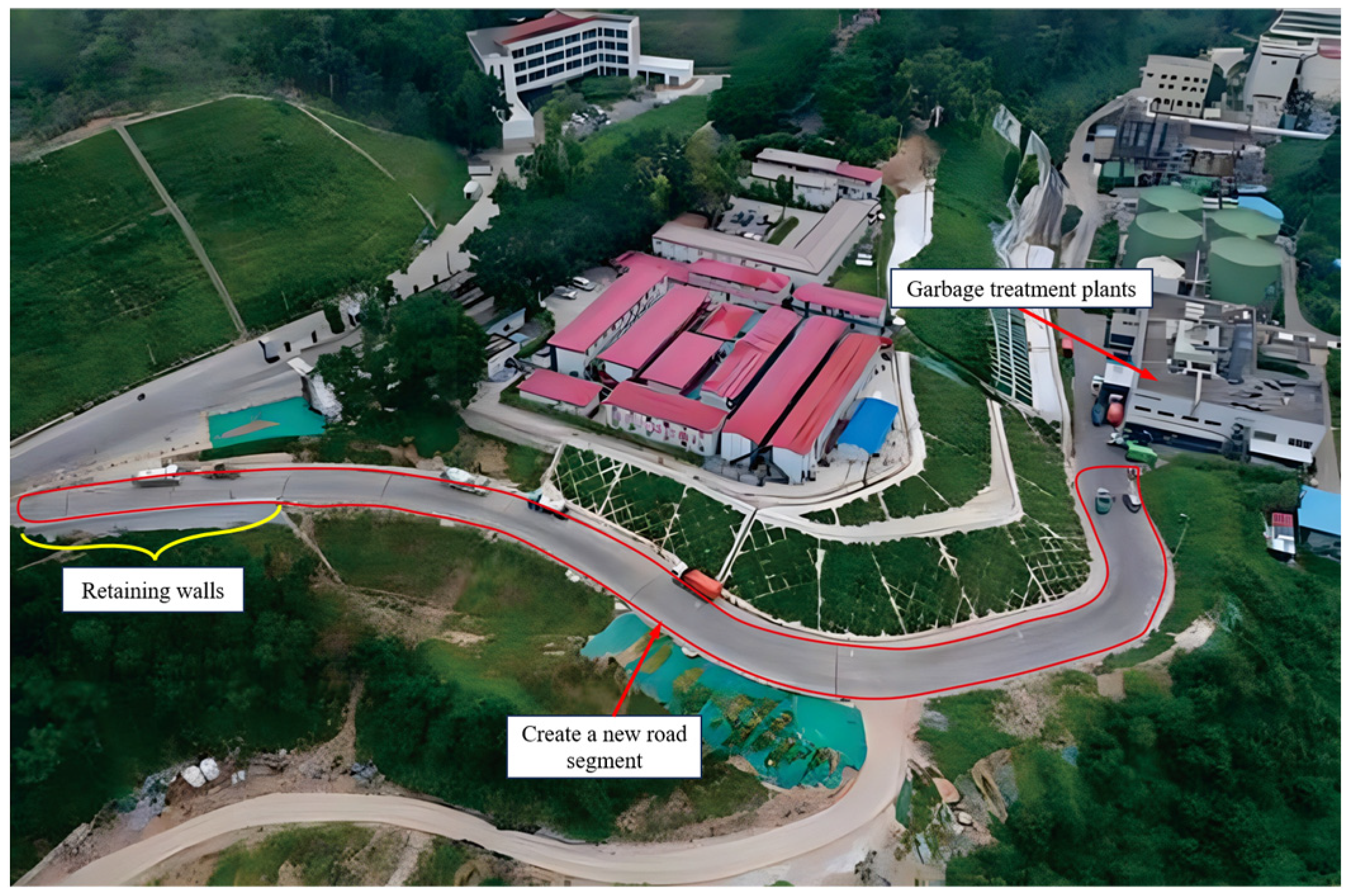
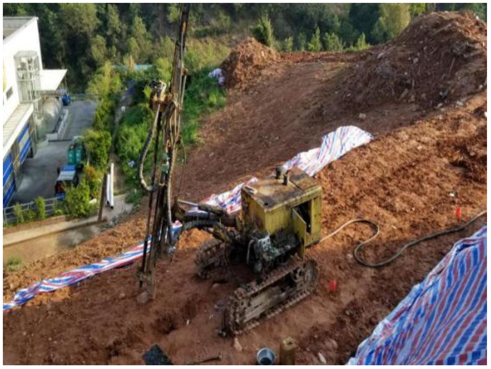
2. Engineering Overview

In the landfill renovation project assessed in this study, it was necessary to build a new 299 m plant-connection channel, as shown in Figure 1. The road base is located on the original construction waste heap, which is mainly composed of construction waste and miscellaneous fill soil such as concrete blocks and bricks, and has the characteristics of considerable thickness, a complex structure, and inconsistent compaction, and thus, cannot be directly used as the bearing layer of the road base and must be reinforced. The design grade of the foundation of the project is B, the sensitivity to settlement deformation is average, and the characteristic value of the bearing capacity of the treated single-pile composite foundation is not less than 175 kPa.
The geological conditions of this new section are as follows: there is a quaternary artificial fill layer from top to bottom, and the underlying bedrock is argillaceous siltstone of the Lower Jurassic Jin Formation. The artificial fill layer is mainly miscellaneous fill, primarily composed of concrete blocks, bricks, and other construction waste and cohesive soil; the content of hard impurities is greater than 45%; the average particle size is 8 cm–15 cm; the structure is loose [27]. The layer thickness is 3.0 m–7.0 m, the average layer thickness is 4.75 m, the buried depth at the bottom of the layer is 7.0 m–54.1 m, and the elevation of the bottom of the layer is 113.0 m–119.9 m. This layer contains ordinary Class I–II soil.

3. Experimental Study on the Technical Parameters of High-Pressure Jet-Grouting Piles in Landfill Sites

3.1. Adaptability Analysis of High-Pressure Jet-Grouting Piles

The foundation composition in this project is complex; the garbage pile is mainly composed of miscellaneous construction waste fill, and an HDPE geomembrane is placed at the bottom of the garbage dump and upstream of the garbage dam to prevent the seepage of landfill leachate and protect groundwater resources. In the literature on road design and construction on landfill bodies, there are few cases of landfill bodies with uneven settlement and complex structure that can be used for reference, and determining what measures to take to avoid the above-mentioned damage has become a design difficulty. Therefore, the key to the treatment of this miscellaneous fill garbage pile soil foundation is to select an appropriate foundation reinforcement method to meet the requirements of foundation design strength, bearing capacity, and economy.
(1)
The construction waste-based miscellaneous fill is deeply buried, and the hard-impurity particles are uneven. The aggregate strength of concrete blocks, bricks, and other aggregates is high, but there is a large gap between the aggregates. If only mechanical compaction is performed, with the passage of time and rainwater infiltration, the foundation will be prone to uneven settlement, which will seriously hinder its later use.
(2)
If the strong compaction method is adopted, the hard impurities will damage the HDPE geomembrane placed under the garbage pile due to strong pressure, resulting in tearing of a large area of the impermeable membrane and the leakage of landfill gas and leachate into the garbage dump, affecting its overall stability; moreover, this would pose considerable safety risks and environmental pollution hazards.
(3)
High-pressure jet-grouting piles are used for foundation reinforcement, using drilling to crush strong aggregates, such as concrete blocks and bricks, and fully mix them with high-pressure cement slurry to form a high-strength columnar body, which plays a role in reinforcing the foundation. For some sections of a construction waste pile stratum with large voids, an appropriate amount of quick-setting agent is mixed into the slurry or the amount of grouting is increased to ensure that the pile is formed.
To summarize, it is most reasonable for the miscellaneous fill garbage pile foundation in this project to be reinforced using high-pressure jet-grouting piles.

3.2. Design Estimation Parameters

The design parameters were preliminarily proposed according to the site conditions of the landfill and the distribution of construction waste, and the characteristic value of the bearing capacity of the composite foundation was comprehensively determined with reference to the design steps carried out before the pile test [27] according to the design estimation and the pile test experiment. The estimation method was as follows:
f s p k = m R a A p + β ( 1 m ) f s k ,
In Equation (1), fspk is the characteristic value of the bearing capacity of the composite foundation; m is the surface area replacement rate (m = d2/de2, m = 0.227); Ap is the cross-sectional area of the pile; Ra is the characteristic value of the vertical bearing capacity of a single pile (it can be calculated according to Equations (2) and (3), and takes the smaller of the calculated results). The physical meaning of m(Ra/Ap) is the bearing capacity of the pile. β is the coefficient of the bearing capacity of the soil between the piles, which is used to convert the actual bearing capacity of the soil between the piles (it can be based on regional experience; 0.4~0.8 can be taken, and this article takes β = 0.7), and fsk is the characteristic value of the bearing capacity of the soil between the piles, which can be determined based on regional experience. The physical meaning of β(1 − m)fsk is the bearing capacity of the soil. Therefore, the addition of the above two terms (m(Ra/Ap) and β(1 − m)fsk) is the bearing capacity of the pile–soil composite foundation.
The characteristic value of the bearing capacity of a single pile was determined through estimation and field testing, and the estimation method was as follows with reference to the design steps [27]:
R a = η f c u A p ,
R a = u p i = 1 n q s i l i + α p q p A p
In Equations (2) and (3), fcu is the compressive strength of the rotary grouting pile; up is the perimeter of the pile; li is the thickness of the first layer of soil within the length of the pile; qsi is the resistance of the pile side, which can be determined based on regional experience; αp is the coefficient of resistance at the end of the pile (0.4~0.6 can be taken, and this article takes αp = 0.4); qp is the characteristic value of the bearing capacity of the pile end, which can be determined based on regional experience; η is the strength reduction coefficient of the pile, obtained by reducing the theoretically calculated bearing capacity (to give a wide enough safety margin to the structural design, this article takes η = 0.3).
In Equations (1)–(3), the estimated characteristic value of the bearing capacity of the composite foundation is 267.8 kPa, meeting the design requirements.

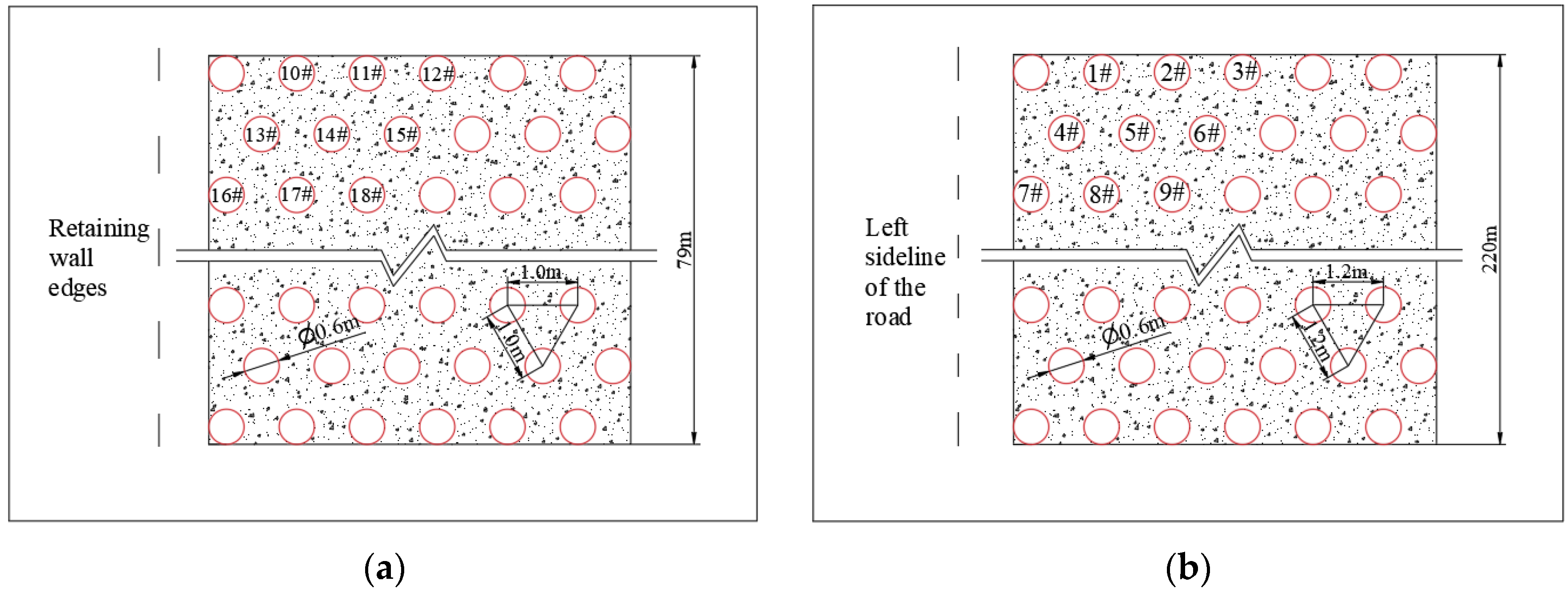
3.3. Experimental Design of Pile Reinforcement

Through the pile test, the geological conditions were further explored; the optimal cement content, water–cement ratio, lifting speed, slurry pressure and air pressure, and other parameters, as well as the optimal construction parameters, were determined in the process of the pile test experiment.
According to the construction experience, the cement content of the pile body was categorized into three grades: 250 kg/m, 275 kg/m, and 300 kg/m; the air pressure ratings were 0.7 Mpa, 0.75 MPa, and 0.80 MPa; the increases in speed level were 0.10 m/min, 0.15 m/min, and 0.20 m/min. We kept the water–cement ratio of 1:1 as a fixed parameter. The slurry pressure remained in the range of 20~30 MPa, with instant adjustments made according to the construction process. This was divided into three groups according to factors such as cement content. There were six test piles for each group of parameters, and the total number of test piles was 18, as shown in Table 1.
The diameter of the experimental jet-grouting pile was d = 60 cm, and the pile length was 14 m. According to the construction experience and design requirements, the 18 above-mentioned test piles were divided into two kinds of pile spacing in a plum blossom arrangement, as shown in Figure 2. A plum blossom-type pile refers to a pile with a position arrangement similar to that of a plum blossom body, with the center of the adjacent two piles forming an equilateral triangle distribution. This arrangement method can ensure uniform pile arrangement, prevent interference between the pile bodies, and is conducive to the formation of continuous and uniform improvement in the soil layer. Compared with straight or square piles, a plum blossom type pile can provide more dense coverage and more uniform bearing capacity distribution. The new road section was divided into two sections. The first was the retaining wall foundation section. According to the design requirements, this section of the road was 79 m long, the high-pressure jet-grouting pile was arranged in a plum blossom shape, and the pile spacing was 1 m, as shown in Figure 2a. This is because the back of the retaining wall was the area where the earth pressure was most directly experienced. Increasing the number of jet-grouting piles effectively improved the resistance of the back of the retaining wall to earthwork pressure, reduced the lateral deformation of the wall, and effectively improved the shear strength of the soil, which is very important for preventing soil slippage and maintaining the overall stability of the retaining wall. The other section had a general subgrade layout; this section of the road was 220 m long with a plum blossom-type arrangement and pile spacing of 1.2 m, as shown in Figure 2b.

3.4. Actual Pile Test Parameters

In the actual operation process, the air pressure and the actual pile length could be controlled using the instrument to reach a standard that conformed to the design. Since there was a certain error between the experimental design and the actual operation when controlling the cement content, these values were within the allowable range of the experimental design. At the same time, the diversity of the data was increased, while the error did not affect the accuracy of the experiment, so as to better observe the influence of the cement content on the experimental results, and the actual parameters of each pile were recorded in the pile testing process (see Table 2 for details).

3.5. Test Excavation and Coring Inspection

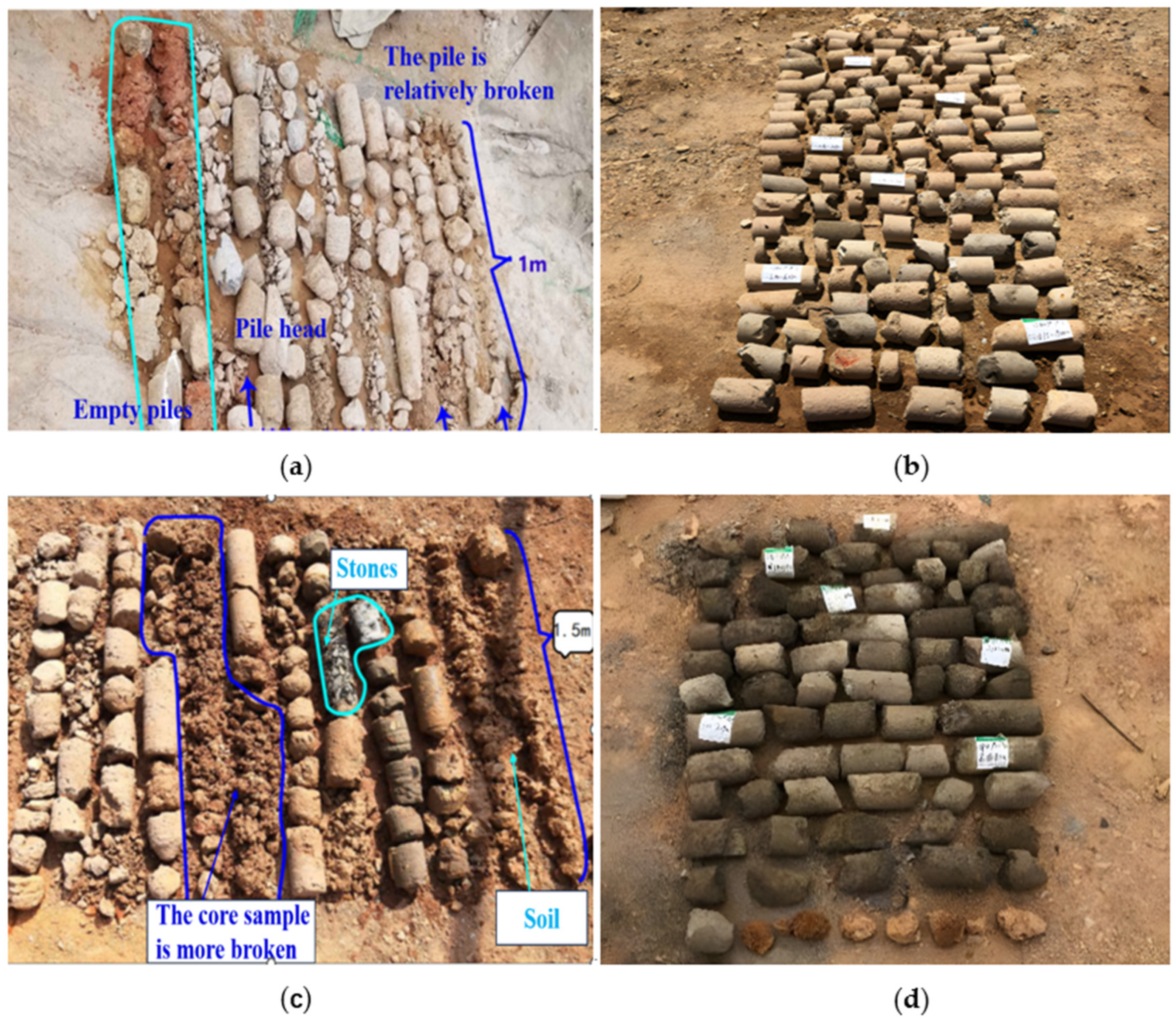
3.5.1. Test Excavation Inspection

The experimental construction of the jet-grouting pile was completed, and the pile diameter and appearance of the test pile were tested after 28 days under standard maintenance conditions. The diameter of the test pile is smaller, at 0.50 m~0.69 m, compared with the diameter of the designed test jet-grouting pile (d = 60 cm). The pile diameter of all the test piles (1, 2, 3, 10, 11, 12) in the first group is 0.50 m~0.59 m, which does not meet the requirements. Of all the test piles, in Group 2 (4, 5, 6, 13, 14, 15) and Group 3 (7, 8, 9, 16, 17, 18), the pile diameter is 0.60 m~0.69 m, meeting the design requirements. The test piles that met the design requirements were excavated and inspected, and the excavation shows that the soil particles in the jet-grouting piles are evenly mixed with the cement slurry, and the integrity is good.

3.5.2. Test Coring Inspection

After the first round of appearance inspection, the bearing capacity and deformation characteristics of the piles were evaluated through drill coring inspection, and the core samples obtained were compared with the design requirements to provide a basis for engineering safety assessment. Through the coring experiment, the quality of the core samples could be observed, and the quality of the piles could be judged, such as determining whether there was difficulty with penetration, external looseness, etc.
In the test piles whose pile diameters met the requirements, 4, 8, 13, and 17 piles were extracted for coring verification. The coring position was 1/4 of the pile diameter outward from the center of the pile cross section, and the coring length was the length of the pile body (vertical drilling coring); we observed the integrity and uniformity of the pile and took photos of the core samples obtained on site, as shown in Figure 3.
The core samples of the No. 8 and No. 17 test piles were obtained, and their GSI of 60 meets the requirements; the No. 4 and No. 13 core samples’ GSI of 20 do not meet the requirements, and their cement contents are 282 kg/m and 279 kg/m, respectively; the No. 5, 6, 14, and 15 piles with lower cement content ceased to be cored.

3.6. Bearing Capacity Test

The single-pile bearing capacity test adopts a stacking platform system. When testing the bearing capacity of a pile, the bearing platform is set up with a steel beam at the top of the pile, heavy objects including sand bags and concrete prefabricated blocks are piled up, and the platform is gradually jacked up using a jack placed on the pile head so that force is applied to the pile body. This stacking method can help engineers evaluate the load-bearing capacity, deformation, and safety performance of a monopile. During the test, a gradually increasing loading force is applied until the monopile reaches its load-bearing limit. The relationship between the loading force and the settlement of the pile top can be used to determine the bearing capacity of the single pile, as shown in Figure 4.
Firstly, the composite bearing capacity of the No. 8 and No. 17 piles that passed the coring verification were tested. If the piles met the bearing capacity requirements and passed the composite foundation bearing capacity test, it would not be necessary to test the No. 7, 9, 16, and 18 test piles with higher cement content.
The slow Virther load method was used to apply the load in 10 stages, and the increased load in each stage was 1/10 of the maximum design load, namely, 35 kPa. When the No. 8 and No. 17 piles are loaded to 350 kPa, the pressure plate settlement of the test is 14.564 mm~15.189 mm, the load settlement curve is slowly deformed, the proportional limit and the ultimate load are not obvious, the bearing capacity of the composite foundation does not reach the limit state in the test process, and the compacting, local shear failure, and complete failure characteristics of the foundation are not obvious, as shown in Figure 5.

3.7. Analysis of Test Results

(1)
After the first round of excavation pile diameter detection, the pile diameter of all the test piles (1, 2, 3, 10, 11, 12) in the first group is 0.50 m~0.59 m, which is smaller than the diameter of the designed test pile of 0.60 m and does not meet the requirements; additionally, its cement content is 248 kg/m~266 kg/m, which does not meet the design requirements. The second (4, 5, 6, 13, 14, 15) and third groups of test piles (7, 8, 9, 16, 17, 18) have diameters of 0.60 m~0.69 m and cement contents of 274 kg/m~314 kg/m which do meet the pile diameter requirements.
(2)
The coring test results show that the core samples of the second group (4 and 13) of test piles are more broken (the cement content is 282 kg/m and 279 kg/m, respectively) and do not meet the design requirements; therefore, the jet-grouting effect of cement content of 282 kg/m and below (piles 5, 6, 14, and 15) cannot meet the design requirements, as shown in Table 3.
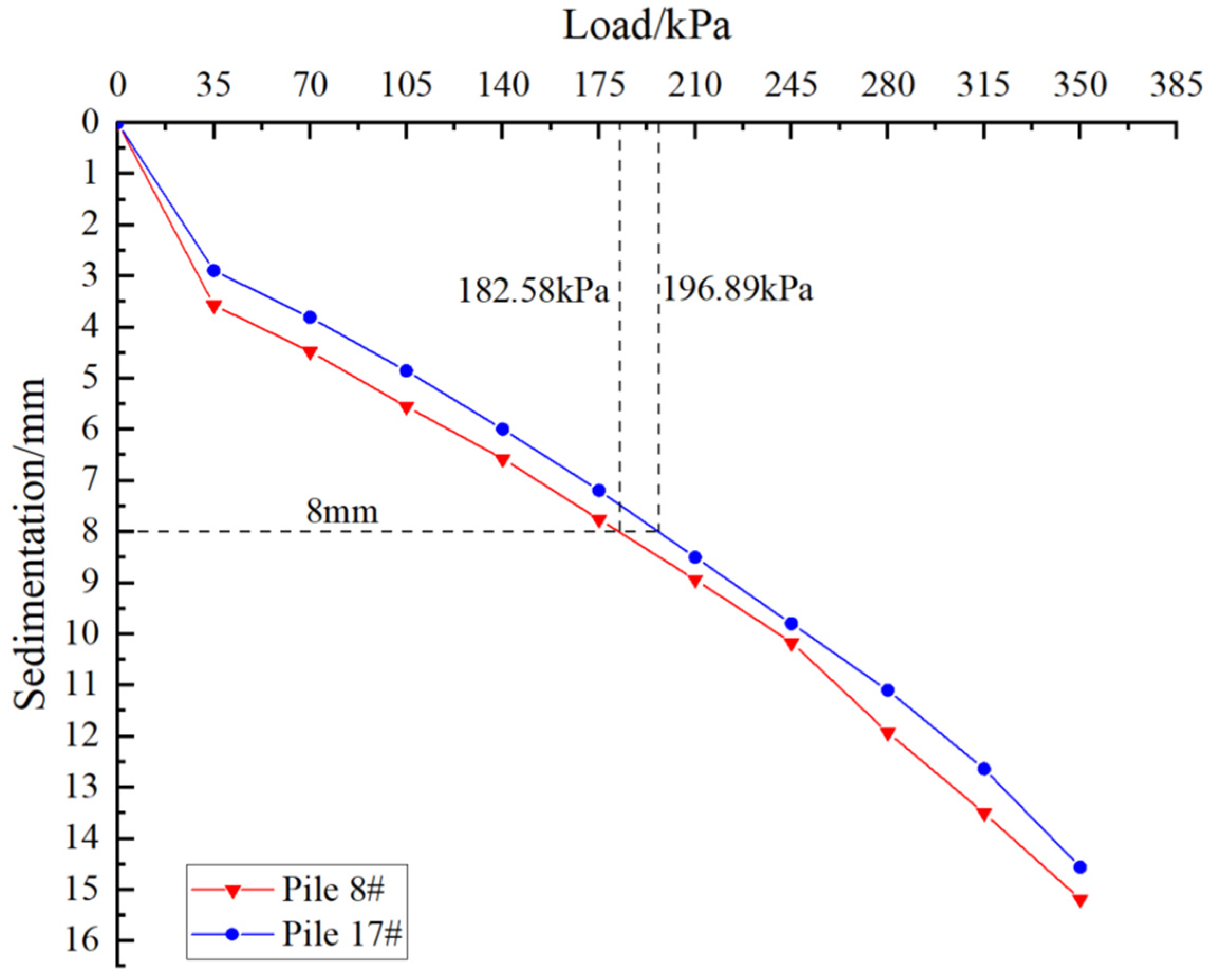
(3)
According to the static load test of the bearing capacity of the single-pile composite foundation of the No. 8 and No. 17 test piles, as shown in Figure 5, the load–settlement curve is slowly deformed, the ultimate load and the proportion limit are not obvious, and the characteristic value of the bearing capacity of the single-pile composite foundation can be determined according to the relative deformation value. Assume a pressure value corresponding to s/b = 0.008 (where s is the settlement of the bearing plate in the static load test, and b is the side length of the bearing plate); in this test, b is 1.0 m, namely, the load value corresponding to s = 0.008 × b = 8.0 mm is the characteristic value of the bearing capacity of the single-pile composite foundation. The characteristic value of the bearing capacity of the single-pile composite foundation obtained in the field test is 182.85 kPa~196.89 kPa, and the characteristic value of the bearing capacity of the foundation, determined using the relative deformation value, should not be greater than half of the maximum load of 350 kPa, and the smaller value is taken. Therefore, the characteristic value of the bearing capacity of the No. 8 and No. 17 monopile composite foundations is 175 kPa, which meets the design requirements. The rotary grouting effect of a minimum cement content of 298 kg/m and above, corresponding to the No. 8 and No. 17 piles, also meets the design requirements.
(4)
The static load test results for the composite foundation are summarized in Table 4. It can be seen that the No. 17 pile has a stronger bearing capacity than the No. 8 pile; this is because the No. 17 pile was tested according to the smaller distance between the piles, and the smaller the pile spacing at the same depth as the foundation soil layer, the more likely it is that the lateral displacement and deformation of the soil between the piles will cancel each other, thereby reducing the overall settlement and deformation of the foundation. Therefore, the settlement of the No. 17 pile is less than that of No. 8.
(5)
Comprehensively considering the on-site pile test construction scenario, test pile test results, economic applicability, and other factors, the following construction standard parameters can be used to guide the construction of high-pressure jet-grouting piles in landfill heaps, and better construction results can be obtained. The specific parameters are shown in Table 5.

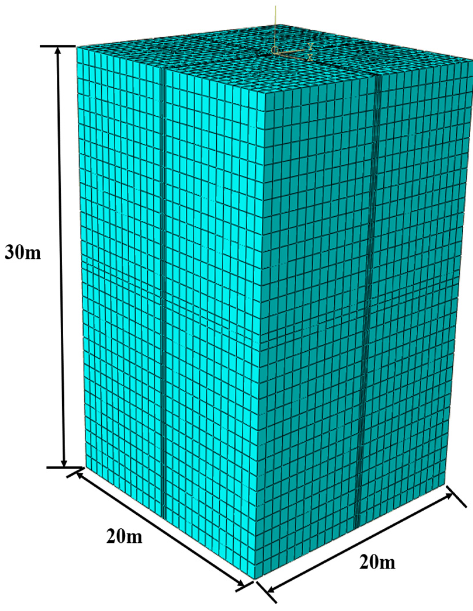
4. Numerical Simulation of Bearing Capacity of Single-Pile Composite Foundation

4.1. Numerical Simulation Establishment and Parameter Selection

In this paper, the ABAQUS finite element software was used to establish a single-pile model of a high-pressure jet-grouting pile, and its composite bearing capacity was simulated and analyzed using the jet-grouting pile. Considering that the boundary effect of the model may interfere with the results, the size of the model site was set to be larger at 20 m × 20 m × 30 m long, as shown in Figure 6. Displacement and rotation angle constraints were carried out on the side of the model, and the bottom surface of the model was fixed. A Mohr–Coulomb plastic model was used for the soil model, because compared with the modified Cam-clay model, it is more suitable for hard rock, sand, and similar geological engineering conditions, and the model is simpler [28,29,30]. The soil was simulated using a C3D8R unit, the drilling position of the soil model was locally infilled, and the model had a total of 86,868 units. The linear elastic model of the pile was also simulated using C3D8R elements, amounting to a total of 8782 elements. In order to make the simulation process more closely resemble the actual engineering practice, 10-stage loading to 350 kPa was used, which is consistent with the actual loading process. A laboratory triaxial compression experiment was carried out on the column core and soil core of the jet-grouting pile obtained from the borehole, and parameters such as the elastic modulus and Poisson’s ratio of the jet-grouting pile and the soil were obtained through the experiment. The parameters of the soil and pile are shown in Table 6.

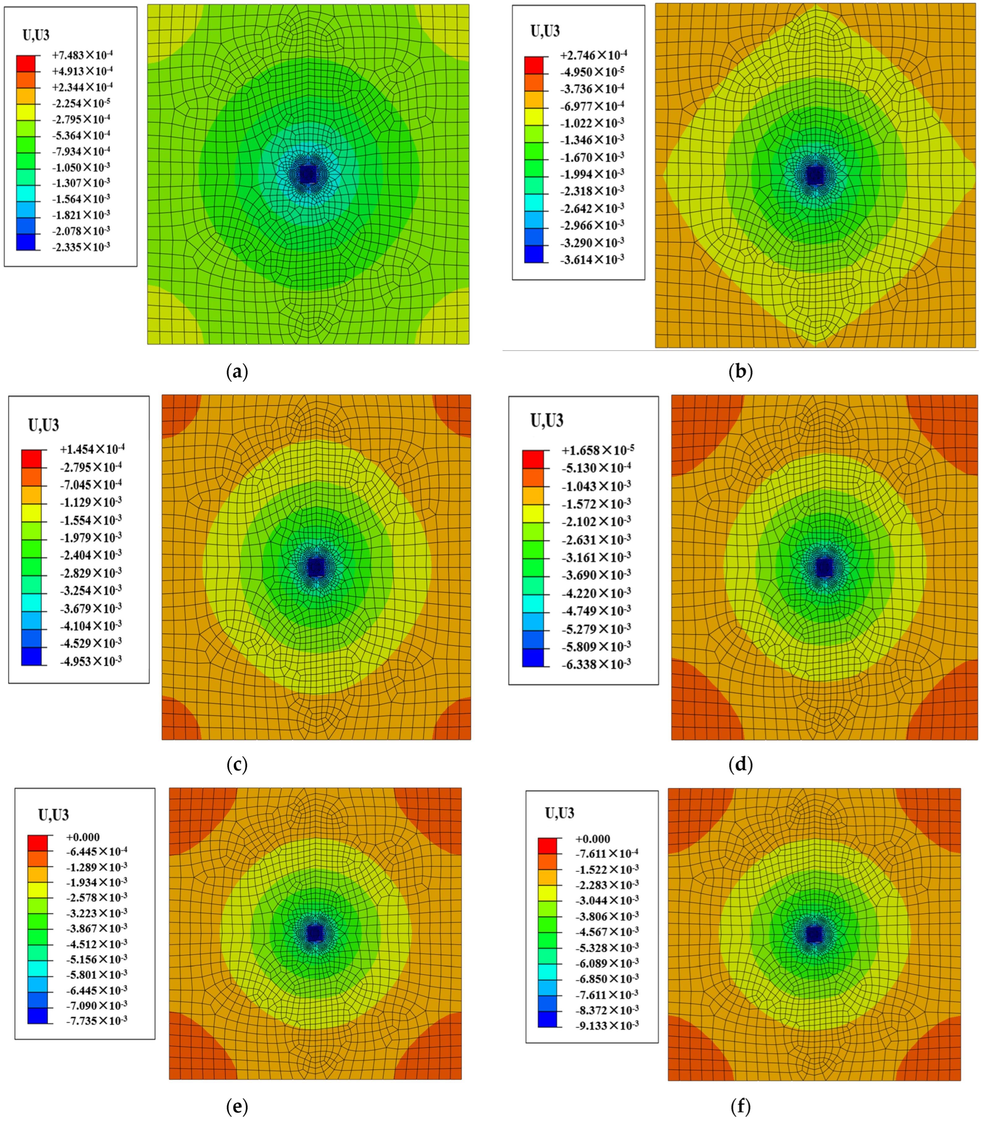
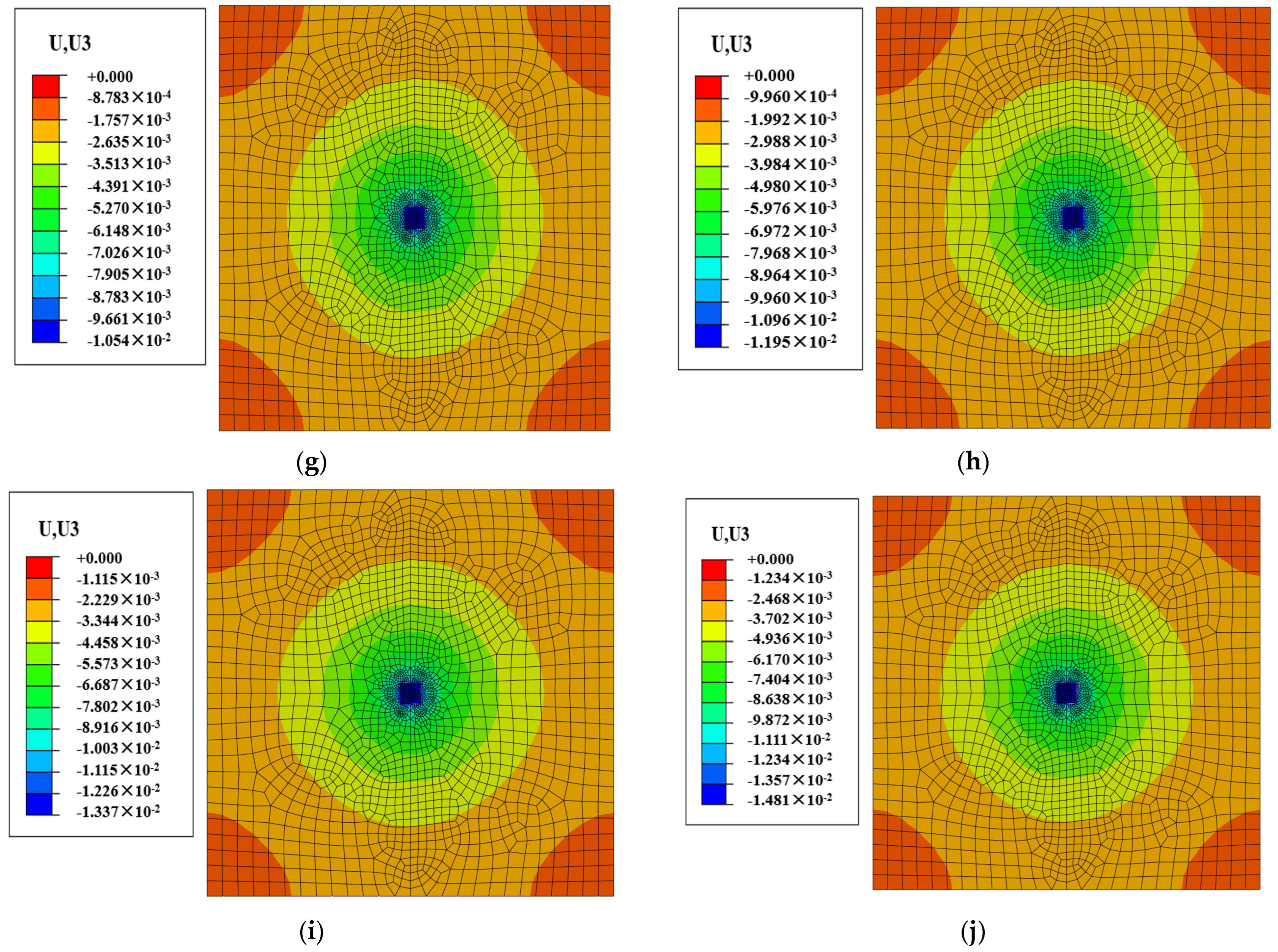
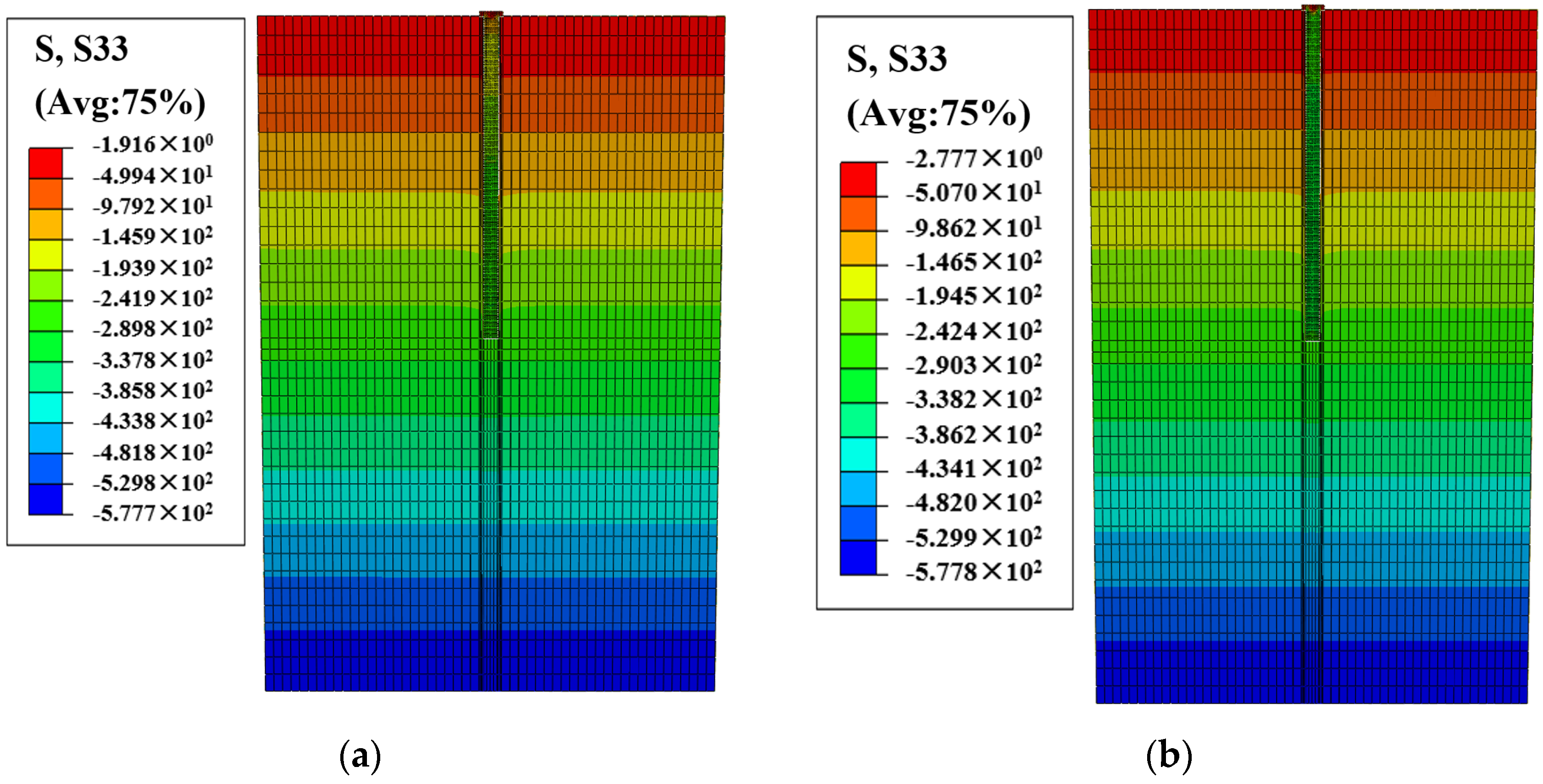
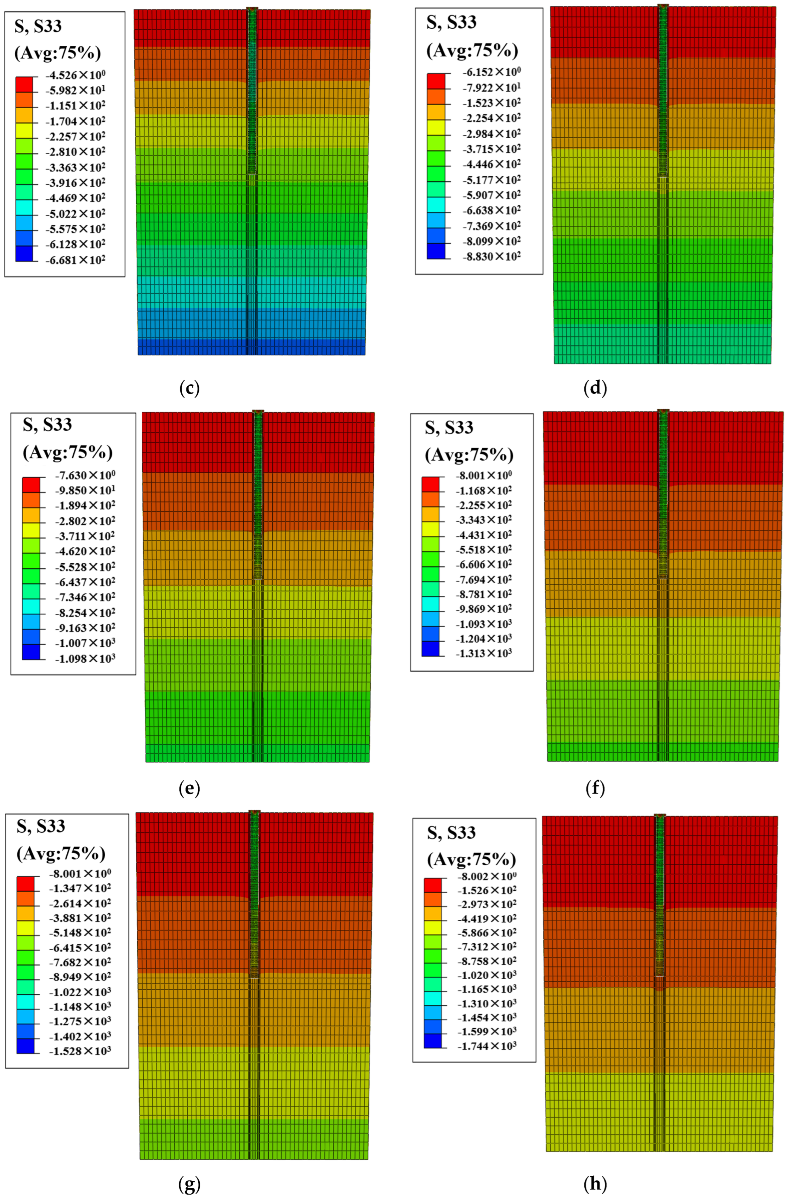
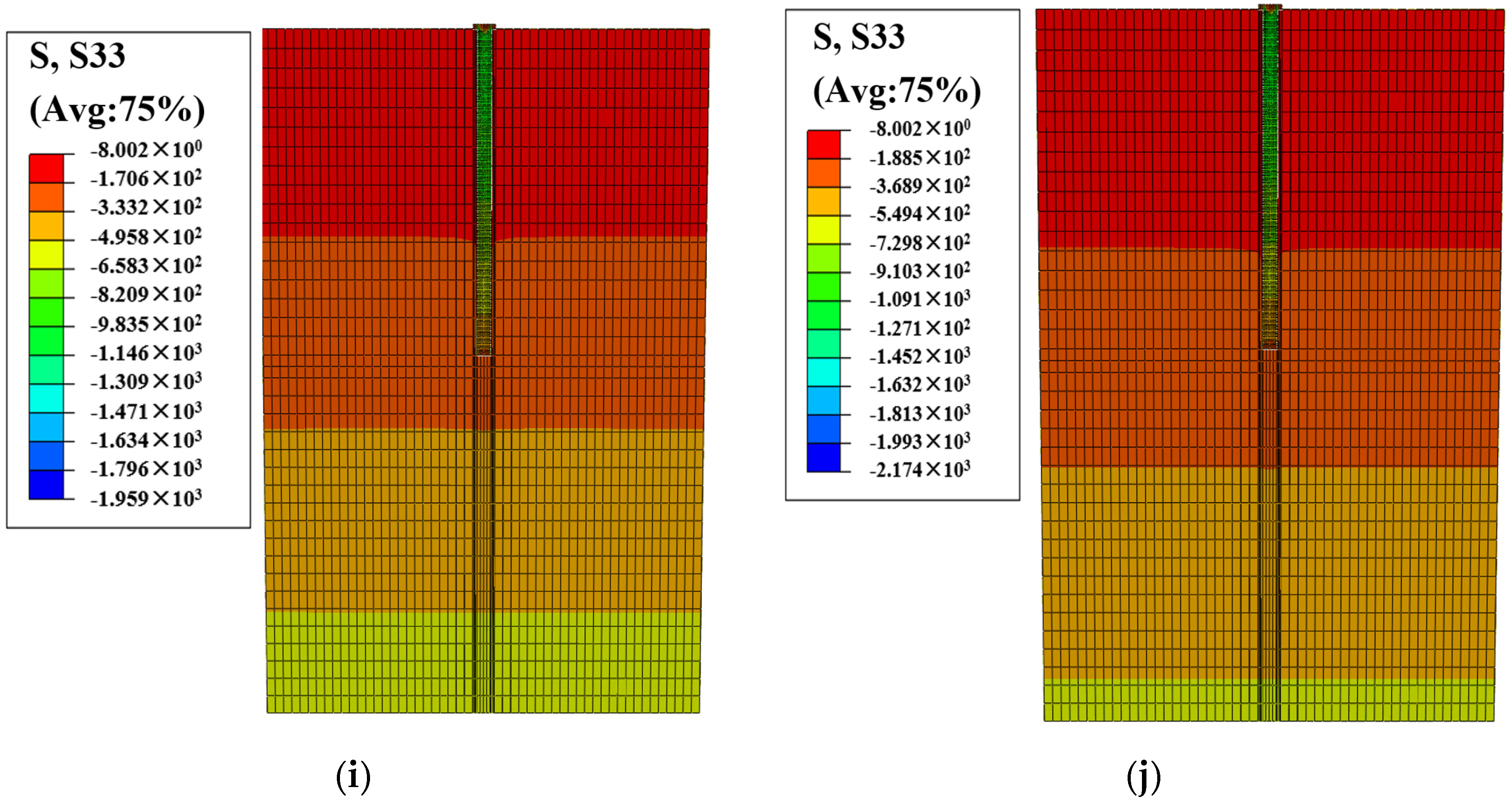
4.2. Numerical Simulation Results and Analysis

The numerical simulation of the step-by-step loading process of a single high-pressure jet-grouting pile was carried out to obtain a strain change contour diagram in the U3 direction of the pile and soil and a stress change contour diagram of the soil and pile in the S3 direction under load during the loading process, as shown in Figure 7 and Figure 8. With the continuous increase in load, the displacement of the surrounding soil is gradually increased with increasing pile settlement, and the settlement within 2.5 m around the pile is the most obvious.
The settlement–load curve obtained through numerical simulation is slowly deformed, the ultimate load and the proportion boundary are not obvious, and the characteristic value of the bearing capacity of the single-pile composite foundation can be determined according to the relative deformation value; the corresponding load value at the settlement of 8 mm is taken as the characteristic value of the bearing capacity of the single-pile composite foundation. The characteristic value of the bearing capacity of the single-pile composite foundation obtained through the numerical simulation is 186.01 kPa, and the load–settlement curve is basically the same as that obtained in the field test; the proportion limit is not obvious and does not reach the bearing limit, and the settlement rate of the composite foundation increases slightly with increasing load. The characteristic value of the bearing capacity of the single-pile composite foundation calculated via numerical simulation is slightly smaller than that obtained in the field test, because the elastic modulus is constant and does not change in the simulation calculation, while the compressive modulus of the soil also increases with increasing load in the field pile test. Secondly, the numerical simulation model is a single-pile load simulation; in contrast to the field test, there is no influence of adjacent piles on a single pile. Additionally, when the pile spacing is reduced in the field test, the soil filler between the adjacent piles will be more constrained, thereby increasing the lateral resistance of the pile, and the interaction between the piles will also be enhanced, further improving the bearing capacity of the pile; therefore, the bearing capacity of the numerical simulation presents a slightly smaller effect of this phenomenon, as shown in Figure 9.
In order to better study the effect of high-pressure jet-grouting piles on the reinforcement of the roadbed, numerical simulation software was used to simulate the plum blossom layout method employed in the actual project, and the surrounding piles were added as shown in Figure 2. Jet-grouting piles with spacing of 1 m were arranged one by one around the above-mentioned simulated single high-pressure jet-grouting pile, and the load–settlement curves of the jet-grouting piles were added through simulation, as shown in Figure 10. The results show that with the increase in the number of surrounding jet-grouting piles, the settlement of a single pile at 35 kPa increases sequentially, because the soil is further compacted by the increase in the number of piles, as shown in Table 7. At the same time, with the increase in the number of surrounding jet-grouting piles, the final settlement gradually decreases; this is because the soil filler between adjacent piles is more constrained, thereby increasing the lateral resistance of the pile, and the interaction between the piles is also enhanced, which will further improve the bearing capacity of the pile. Therefore, under the action of surrounding piles, the subgrade reinforcement effect is better.

5. The Construction Process of High-Pressure Jet-Grouting Piles in Landfills

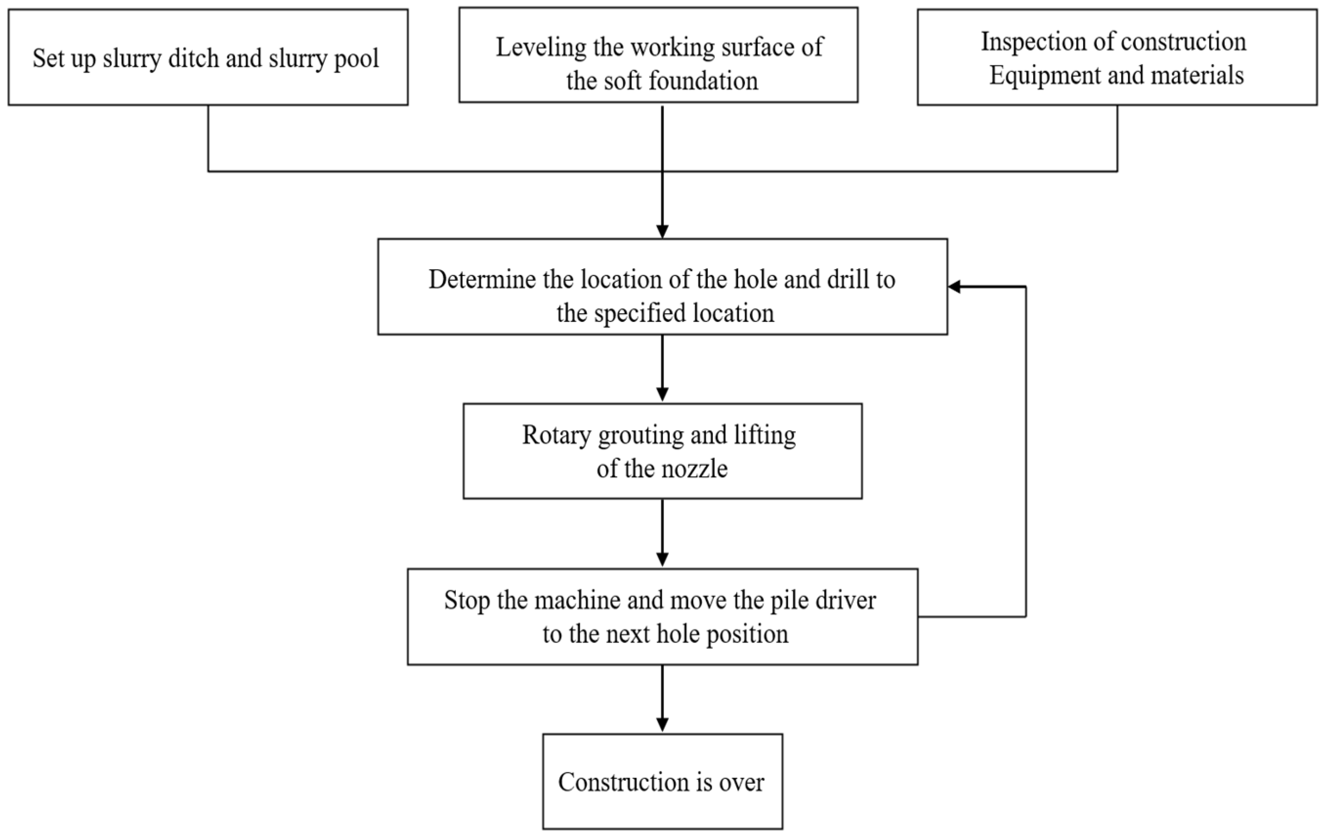
5.1. Construction Process

According to the construction parameters of the jet-grouting pile utilized in the above-mentioned test analysis, construction can be guided and carried out according to the construction process outlined in Figure 11.

5.2. Construction Process Control

The construction equipment and required materials should be inspected to ensure the normal operation and safety of the rotary spraying machine, room press, conveyor pipe, and other equipment. Before construction, the slurry ditch and slurry pool around the site must be set up, and after construction, the slurry from rotary spraying and wastewater from mechanical flushing should be discharged into the slurry pool along the slurry ditch; they must not be scattered and discharged at will so as to prevent the grout from further scouring the substrate clay, aggravating its cracking and deformation, and even causing settlement and collapse.
According to the design drawings and site markings, one should determine the position and spacing of each pile, and make a mark. There are different slopes on the site of this project, which is conducive to the accurate positioning of the hole position using GPS measuring instruments, determining the pile position, and measuring the position and elevation of the hole. The pilot drilling procedure is as follows: place the pilot drilling rig in the designated position to ensure the stability and safety of the drilling equipment, as shown in Figure 12; start drilling according to the design requirements, and carry out this operation for each pile separately; pass through the covering layer, comprising materials such as solitary stone and construction waste, and ensure that the pile length meets the design requirements, as shown in Figure 13.
After the jet-grouting pile pipe reaches a predetermined depth, a high-pressure water jet test should be carried out, and after the predetermined pressure displacement is reached, the jet nozzle should be sprayed first, and then, continuously and slowly lifted to prevent the nozzle from being twisted and strictly control the amount and time of the jet; it is strictly forbidden to pull out the rotary nozzle quickly and indiscriminately. If failure interrupts the rotary spraying, if the downtime is less than 2 h, it is necessary to drill down to 0.5 m again, and then, start the spray lifting; if the downtime is more than 2 h, it is necessary to start the rotary spraying again from the bottom of the pile.
One should strictly control the spraying pressure, spraying time, and nozzle lifting speed. Keeping the spraying pressure stable and ensuring the spraying liquid is evenly sprayed into the soil are key to ensure the quality of the pile. When the nozzle is lifted, the spraying time, spray continuity, and lifting speed should be strictly controlled, and the nozzle should not be lifted at will, as shown in Figure 14. The construction site needs to have technicians and foremen on duty to check whether parameters such as spraying pressure, nozzle lifting length, and lifting speed meet the requirements, and to keep records at all times.
The selection of cement should be tested and screened, and its fineness should be equal to that of a standard sieve (aperture 0.08 mm) with a sieve allowance of no more than 15%. During the production of slurry, one must strictly control the amount of cement and water–cement ratio. Next to the slurry mixer, detailed statistics should be recorded on the amount of cement on site, the consumption of cement, and the remaining amount. In the process of jet spraying, the slurry should be stirred frequently to prevent precipitation and concentration changes affecting the strength of the column, and the waiting time for pumping after the slurry is stirred must not exceed 4 h.

5.3. Problems Encountered in the Construction Process and Measures to Mitigate Them

(1)
There are large voids in some sections of construction waste heaps. If there is no slurry in the drilling process, an appropriate amount of quick-setting agent can be added to the slurry; as a result, the consolidation time is shortened, and the grout is solidified within a certain range.
(2)
A large amount of slurry in the drilling process is caused by incompatibility between the effective spraying range and the amount of grouting. Measures such as increasing the injection pressure, appropriately reducing the nozzle diameter, and speeding up the lifting and rotary spraying speed can be taken to reduce the amount of slurry.
(3)
Due to the solidification process of mixing grout with the miscellaneous fill, slurry water precipitation will occur, and there will be different degrees of pile shrinkage, resulting in depression during consolidation (this depression is usually between 0.3 m and 1 m at the top of the pile), and the depth varies with the soil quality, slurry precipitation, solid diameter, and other factors.

6. Conclusions

At present, high-pressure jet-grouting piles are widely used in the engineering fields of foundation reinforcement, foundation treatment, waterproof curtains, etc., but due to the diversity of geological conditions, the stress characteristics, treatment effects, and inspection methods of this technology need to be discussed in depth. In this paper, based on the foundation reinforcement project of a new plant in a landfill in Shenzhen, the bearing capacity and reinforcement effects of foundation pile-forming and single-pile composite foundations dominated by construction waste are discussed and studied through a core pulling test of high-pressure jet-grouting piles, a static load test of the bearing capacity of a single-pile composite foundation, design estimation, and numerical analysis, and the following conclusions are drawn.
(1)
Regarding the thickness of the foundation soil layers composed of miscellaneous fill mainly from the building garbage pile, its composition is complex, and its treatment is difficult. A high-pressure jet-grouting pile composite foundation is used to reinforce the foundation soil, and the construction technology is simple, the reinforcement effect is remarkable, and a considerable amount of cement mortar is saved.
(2)
The test results show that the cement content has a significant impact on the bearing capacity of the single-pile composite foundation, and through the testing of the bearing capacity of the single pile and the composite foundation, the construction index of cement content greater than 300 kg/m is found to meet the design requirements. Through the comparison of different cement content results, a suitable cement dosage is found that can save costs to a certain extent and meet the needs of economic applicability. In the process of spraying the rotary grouting pile, the spraying pressure can be strictly controlled, and the spraying liquid can be evenly sprayed into the soil and fully mixed with the crushed soil to form a consolidated cement body to ensure the quality of the pile.
(3)
The characteristic value of the bearing capacity of the single-pile composite foundation obtained from the field test lies between 182.58 kPa and 196.89 kPa. The characteristic value of the bearing capacity of the numerical simulation of the single-pile composite foundation obtained through the ABAQUS numerical simulation is 186.01 kPa, which is slightly smaller than the value obtained in the field test, but the difference is small. Therefore, when field test conditions are not available, the characteristic value of the bearing capacity of the composite foundation can be used as a construction reference.
(4)
In the simulation of adding jet-grouting piles one by one around the high-pressure jet-grouting piles of a single pile, it is shown that with an increase in the number of jet-grouting piles in the actual project, the overall bearing capacity of the foundation will be stronger than that obtained in the simulation of a single pile, and the subgrade reinforcement effect will be better.

Author Contributions

Conceptualization, T.W. and L.L.; methodology, T.W., X.L. and L.L.; software, T.W. and X.L.; validation, T.W., X.L. and L.L.; formal analysis, T.W., X.L. and L.L.; investigation, W.X. and Z.L.; resources, T.W. and L.L.; data curation, W.X. and Z.L.; writing—original draft preparation, T.W. and X.L.; writing—review and editing, T.W., X.L. and L.L.; visualization, T.W., X.L. and L.L.; supervision, W.X. and Z.L.; project administration, L.L.; funding acquisition, T.W. and L.L. All authors have read and agreed to the published version of the manuscript.

Funding

This work was funded by the National Natural Science Foundation of China (Grant Nos. 51874014 and 52311530070), the fellowship of the China National Postdoctoral Program for Innovative Talents (Grant No. BX2021033), the fellowship of the China Postdoctoral Science Foundation (Grant Nos. 2021M700389 and 2023T0025), and the Fundamental Research Funds for the Central Universities of China (Grant No. FRF-IDRY-20-003, Interdisciplinary Research Project for Young Teachers of USTB). This support is gratefully acknowledged.

Data Availability Statement

The raw data supporting the conclusions of this article will be made available by the authors on request.

Conflicts of Interest

Author Zhenyun Li was employed by the company China Railway Second Bureau Fifth Engineering Co., Ltd. The remaining authors declare that the research was conducted in the absence of any commercial or financial relationships that could be construed as a potential conflict of interest.

References

  1. Gao, S.; Meng, L.; Ge, X.; Li, Y.; Yang, Y.; Duan, Y.; Fu, Q.; Zhang, S.; Yang, X.; Fei, W.; et al. Role of garbage classification in air pollution improvement of a municipal solid waste disposal base. J. Clean. Prod. 2023, 423, 138737. [Google Scholar] [CrossRef]
  2. Liu, L.; Ji, H.; Lv, X.; Wang, T.; Zhi, S.; Pei, F.; Quan, D. Mitigation of greenhouse gases released from mining activities: A review. Int. J. Miner. Metall. Mater. 2021, 28, 513–521. [Google Scholar] [CrossRef]
  3. Dong, J.; Zhao, Y.; Zhang, W.; Hong, M. Laboratory study on sequenced permeable reactive barrier remediation for landfill leachate-contaminated groundwater. J. Hazard. Mater. 2009, 161, 224–230. [Google Scholar] [CrossRef] [PubMed]
  4. Jewaskiewitz, S.M. The rehabilitation of the New England Road landfill in Pietermaritzburg—A case study. Civ. Eng. 1995, 1995, 21–25. [Google Scholar]
  5. Yamawaki, A.; Doi, Y.; Omine, K. Slope stability and bearing capacity of landfills and simple on-site test methods. Waste Manag. Res. 2017, 35, 730–738. [Google Scholar] [CrossRef] [PubMed]
  6. Holzlöhner, U.; Meggyes, T.; Seeger, S. Landfill technology in Germany. Land Contam. Reclam. 1999, 7, 109–119. [Google Scholar]
  7. Rong, L.; Zhang, C.; Jin, D.; Dai, Z. Assessment of the potential utilization of municipal solid waste from a closed irregular landfill. J. Clean. Prod. 2017, 142, 413–419. [Google Scholar] [CrossRef]
  8. Zhao, C.; Zhao, D. Application of construction waste in the reinforcement of soft soil foundation in coastal cities. Environ. Technol. Innov. 2021, 21, 101195. [Google Scholar] [CrossRef]
  9. Liu, L.; Zhang, Z.; Wang, T.; Zhi, S.; Wang, J. Evolution characteristics of fracture volume and acoustic emission entropy of monzogranite under cyclic loading. Geomech. Geophys. Geo-Energy Geo-Resour. 2024, 10, 16. [Google Scholar] [CrossRef]
  10. Krook, J.; Svensson, N.; Eklund, M. Landfill mining: A critical review of two decades of research. Waste Manag. 2012, 32, 513–520. [Google Scholar] [CrossRef]
  11. Fan, H.; Xu, Q.; Lai, J.; Liu, T.; Zhu, Z.; Zhu, Y.; Gao, X. Stability of the loess tunnel foundation reinforced by jet grouting piles and the influence of reinforcement parameters. Transp. Geotech. 2023, 40, 100965. [Google Scholar] [CrossRef]
  12. Nguyen, X.L.; Wu, L.; Nguyen, K.T.; Bui, Q.A. Application research of high pressure jet grouting pile in an underground engineering in Vietnam. Arch. Civ. Eng. 2020, 66, 575–593. [Google Scholar] [CrossRef]
  13. Li, P.; Huang, X.; Lu, F.; Qiu, W.; Liu, H.; Li, L.; Wang, Y.; Chen, Z.; He, Z. Experimental investigation on the reinforcement of a high-pressure jet grouting pile for an ultra-shallow tunnel in a strongly weathered stratum. Front. Earth Sci. 2023, 10, 1040461. [Google Scholar] [CrossRef]
  14. Wei, J.Y.; Wang, B.T.; Zhang, J.H.; Zhou, B. Application of High Pressure Jet Grouting Pile with Undrained Open Caisson Combined Construction Technology in the Protection of Yangtze River Levee. Appl. Mech. Mater. 2013, 368, 1443–1449. [Google Scholar] [CrossRef]
  15. Ho, C.E.; Lim, C.H.; Tan, C.G. Jet grouting applications for large-scale basement construction in soft clay. In Innovations in Grouting and Soil Improvement; ASCE: Reston, VA, USA, 2005; pp. 1–15. [Google Scholar]
  16. Qiu, J.; Liu, H.; Lai, J.; Lai, H.; Chen, J.; Wang, K. Investigating the long-term settlement of a tunnel built over improved loessial foundation soil using jet grouting technique. J. Perform. Constr. Facil. 2018, 32, 04018066. [Google Scholar] [CrossRef]
  17. Li, Y.; Xu, S.; Liu, H.; Ma, E.; Wang, L. Displacement and stress characteristics of tunnel foundation in collapsible loess ground reinforced by jet grouting columns. Adv. Civ. Eng. 2018, 2018, 2352174. [Google Scholar] [CrossRef]
  18. Li, Z.; Zhao, J.; Hu, K.; Li, Y.; Liu, L. Adaptability Evaluation of Rotary Jet Grouting Pile Composite Foundation for Shallow Buried Collapsible Loess Tunnel. Appl. Sci. 2023, 13, 1570. [Google Scholar] [CrossRef]
  19. Dong, L. Numerical model for the settlement of loess subgrade in operation period reinforced by rotary jet grouting pile. Vibroeng. Procedia 2022, 41, 48–53. [Google Scholar] [CrossRef]
  20. Zhang, Y.; Qi, H.; Li, C.; Zhou, J. Enhancing safety, sustainability, and economics in mining through innovative pillar design: A state-of-the-art review. J. Saf. Sustain. 2023; in press. [Google Scholar] [CrossRef]
  21. Yuan, C.; Xie, Y.; Ou, M. Adaptive Optimization Method for Piled Raft Foundations Based on Variable Pile Spacing. Appl. Sci. 2023, 13, 1648. [Google Scholar] [CrossRef]
  22. Soga, K.; Alonso, E.; Yerro, A.; Kumar, K.; Bandara, S. Trends in large-deformation analysis of landslide mass movements with particular emphasis on the material point method. Géotechnique 2016, 66, 248–273. [Google Scholar] [CrossRef]
  23. Conte, E.; Pugliese, L.; Troncone, A.; Vena, M. A simple approach for evaluating the bearing capacity of piles subjected to inclined loads. Int. J. Geomech. 2021, 21, 04021224. [Google Scholar] [CrossRef]
  24. Yu, J.L.; Zhou, J.J.; Gong, X.N.; Xu, R.Q.; Li, J.Y.; Xu, S.D. Centrifuge study on behavior of rigid pile composite foundation under embankment in soft soil. Acta Geotech. 2021, 16, 1909–1921. [Google Scholar] [CrossRef]
  25. Wang, T.; Ye, W.; Liu, L. Study on the Mechanical Properties and Acoustic Emission Signal Characteristics of Freezing Pipe. Front. Earth Sci. 2023, 11, 1298025. [Google Scholar] [CrossRef]
  26. Liang, H.; Shi, L.; Wang, D.; Xiao, X.; Deng, K. Influence of graded coarse aggregate content and specific surface area on the fracture properties of asphalt mixtures based on discrete element simulations and indoor tests. Constr. Build. Mater. 2021, 299, 123942. [Google Scholar] [CrossRef]
  27. Zhu, D.L.; Wang, W.J.; Xie, X.Y.; Zheng, L.W. Reinforcement case of high-pressure rotary jet grouting pile for thick construction waste miscellaneous fill foundation. Build. Struct. 2020, 50, 116–120. [Google Scholar]
  28. Kavvadas, M.; Amorosi, A. A constitutive model for structured soils. Géotechnique 2000, 50, 263–273. [Google Scholar] [CrossRef]
  29. Savvides, A.A.; Papadrakakis, M. A computational study on the uncertainty quantification of failure of clays with a modified Cam-Clay yield criterion. SN Appl. Sci. 2021, 3, 659. [Google Scholar] [CrossRef]
  30. Troncone, A.; Pugliese, L.; Parise, A.; Conte, E. A simple method to reduce mesh dependency in modelling landslides involving brittle soils. Géotech. Lett. 2022, 12, 167–173. [Google Scholar] [CrossRef]
Figure 1. Schematic diagram of new plant with access road.
Buildings 14 00444 g001
Figure 2. Pile position arrangement: (a) 1 m pile spacing layout drawing; (b) 1.2 m pile spacing layout drawing. (The “#” symbol in the figure represents a pile. For instance, “1#” denotes pile 1).
Buildings 14 00444 g002
Figure 3. The core samples were taken on site: (a) No. 13 pile core sample; (b) No. 8 pile core sample; (c) No. 4 pile core sample; (d) No. 17 pile core sample.
Buildings 14 00444 g003
Figure 4. Pile bearing capacity detection: (a) No. 8 pile; (b) No. 17 pile.
Buildings 14 00444 g004
Figure 5. Load–settlement curve of single-pile composite foundation.
Buildings 14 00444 g005
Figure 6. Three-dimensional soil and pile combination model.
Buildings 14 00444 g006
Figure 7. Strain contour diagram of pile soil under different loading processes: (a) 35 kPa; (b) 70 kPa; (c) 105 kPa; (d) 140 kPa; (e) 175 kPa; (f) 210 kPa; (g) 245 kPa; (h) 280 kpa; (i) 315 kpa; (j) 350 kpa.
Buildings 14 00444 g007aBuildings 14 00444 g007b
Figure 8. Vertical stress of soil: (a) 35 kPa; (b) 70 kPa; (c) 105 kPa; (d) 140 kPa; (e) 175 kPa; (f) 210 kPa; (g) 245 kPa; (h) 280 kpa; (i) 315 kpa; (j) 350 kpa.
Buildings 14 00444 g008aBuildings 14 00444 g008bBuildings 14 00444 g008c
Figure 9. Numerical simulation of load–settlement curves of single-pile composite foundations.
Buildings 14 00444 g009
Figure 10. Load–settlement curve of a single-pile composite foundation when the pile spacing is 1 m.
Buildings 14 00444 g010
Figure 11. High-pressure jet-grouting pile construction process flow chart.
Buildings 14 00444 g011
Figure 12. Pilot drill rig in place.
Buildings 14 00444 g012
Figure 13. Pilot drill rig drilling.
Buildings 14 00444 g013
Figure 14. Lifting drill pipe during jet spraying.
Buildings 14 00444 g014
Table 1. Parameters of pile test.
Group NumberStation
(Spacing of 1.2 m)
Station
(Spacing of 1.0 m)
Cement Content (kg/m)Water–Cement RatioLift Speed (cm/min)Slurry Pressure (MPa)Air Pressure
(MPa)
11#10#2501:10.1020~300.70
2#11#0.150.75
3#12#0.200.80
24#13#2751:10.1020~300.70
5#14#0.150.75
6#15#0.200.80
37#16#3001:10.1020~300.70
8#17#0.150.75
9#18#0.200.80
“#” is the mark for the pile. For example, pile 1 is denoted by “1#”.
Table 2. Actual pile test parameter table.
Group NumberStationCement Content
(kg/m)
Water–Cement RatioLift Speed
(cm/min)
Slurry Pressure
(MPa)
Air Pressure
(MPa)
11#2661:10.12200.70
2#2550.16210.75
3#2480.23220.80
10#2640.11200.70
11#2560.16210.75
12#2500.22220.80
24#2821:10.12230.70
5#2790.22240.80
6#2740.15250.75
13#2790.11230.70
14#2770.21240.80
15#2750.17250.75
37#3141:10.12260.70
8#2990.14280.75
9#3070.22270.80
16#3130.12260.70
17#2980.14280.75
18#3050.21270.80
“#” is the mark for the pile. For example, pile 1 is denoted by “1#”.
Table 3. Summary of preliminary screening of pile diameter and core sample results.
Group NumberStationDiameter of Jet-Grouting Pile (m)The Degree of Pile Core FragmentationCement Content (kg/m)Are the Design Requirements Met?
11#0.55-266no
2#0.56-255no
3#0.57-248no
10#0.50-264no
11#0.56-256no
12#0.59-250no
24#0.60broken282no
5#0.62-279no
6#0.60-274no
13#0.60broken279no
14#0.62-277no
15#0.65-275no
37#0.69-314yes
8#0.66complete299yes
9#0.65-307yes
16#0.64-313yes
17#0.63complete298yes
18#0.60-305yes
The “#” symbol in the figure represents a pile. For instance, “1#” denotes pile 1.
Table 4. Static load test results for composite foundation.
StationMaximum Test Load (kPa)Eventual Settlement (mm)Eigenvalues of Bearing Capacity (kPa)Cement Content (kg/m)
8#35015.189182.58299
17#35014.564196.89298
Table 5. Standard parameter table for the construction of jet-grouting piles.
ParameterCement Parameters (kg/m)Water–Cement RatioLift Speed (cm/min)Spraying Pressure (MPa)Air Pressure (MPa)Rotary Spray Speed (r/min)
Index3001:12020~280.720
Table 6. Pile and soil layer parameters.
Material CategoryModulus of Elasticity (MPa)Poisson’s RatioSevere (kN·m−3)Cohesion (kPa)Internal Friction Angle (°)
Jet-grouting pile10,5000.221.5--
Plain fill3.10.3519.59810
Miscellaneous fill3.30.3319.6812
Strongly weathered argillaceous siltstone10.20.1520.23028
Table 7. Relationship between the settlement of intermediate piles and the increase in the number of piles when the load is 35 kPa.
Increase in the number of piles123456
The amount of settlement of intermediate piles (mm)2.45092.71712.94453.13493.32793.3851
Disclaimer/Publisher’s Note: The statements, opinions and data contained in all publications are solely those of the individual author(s) and contributor(s) and not of MDPI and/or the editor(s). MDPI and/or the editor(s) disclaim responsibility for any injury to people or property resulting from any ideas, methods, instructions or products referred to in the content.

