Article

Investigating the Influence of the Improved Multibody Rope Approach on the Structural Behavior of Dakar Mosque Gridshell Structure

by
Jonathan Melchiorre
,
Stefano Invernizzi
and
Amedeo Manuello Bertetto
*
DISEG, Department of Structural, Geotechnical and Building Engineering, Politecnico di Torino, Corso Duca Degli Abruzzi, 24, 10128 Turin, Italy
*
Author to whom correspondence should be addressed.
Buildings 2024, 14(3), 598; https://doi.org/10.3390/buildings14030598
Submission received: 18 January 2024 / Revised: 13 February 2024 / Accepted: 21 February 2024 / Published: 23 February 2024
(This article belongs to the Section Building Structures)

Abstract

:
Gridshell structures are characterized by an impressive strength-to-weight ratio, allowing their application in large-span roofing structures. However, their complex construction process and maintenance limited their widespread application. In recent years, the development of parametric and computational design tools has rekindled interest in this type of structure. Among these techniques, the Multibody Rope Approach (MRA) is a form-finding method based on the dynamic equilibrium of a system of masses (nodes) connected by ropes, which allows optimizing the structural shape starting from the dual geometry of the funicular network. To optimize the construction process, an improved version of the MRA, i-MRA, has been recently developed by the authors with the goal of uniforming the size of the structural components. To investigate the impact of the i-MRA method on the structural behavior of gridshell structures, the practical case of the design of a mosque roof is here analyzed. The comparison is carried out in terms of structural performance with respect to permanent and equivalent quasi-static loads. In addition, free-vibration natural-frequency shift is obtained by performing linear modal analysis. Finally, the global behavior with respect to buckling and elastic instability is assessed solving the relevant eigenvalue problem. The results demonstrate that for the roofing of the Dakar mosque, the structural configuration obtained through i-MRA is superior in terms of both construction efficiency and structural performance. The achieved shape exhibits a more uniform distribution of stresses induced by the applied loads together with very limited structural element typologies.

1. Introduction

Architecture and structure are two essential and interconnected elements that have undergone continuous evolution in response to societal changes. This dynamic relationship has played a crucial role in shaping various structural typologies [1,2]. In particular, this paradigm finds significant relevance in understanding the unique characteristics of long-span spatial structures, with particular reference to shell and gridshell structures [3,4]. Throughout the past century, the exploration of different form-finding and optimization [5,6] techniques has emerged as valuable tools to address structural requirements while shaping the overall architectural expression.New methods of gridshell design were introduced in the 1960s and 1970s by engineers and architects such as Ted Happold [7,8] and Frei Otto [9]. They created complex, double-curved structures using computer modeling and lightweight materials. Early gridshells were often constructed from fabric or wood [10], and they were used to construct large open-area structures. The limits of gridshell design have been pushed by engineers and architects in recent decades thanks to developments in digital design and fabrication technology. These days, steel [11,12], aluminum [13], wood [14,15,16,17], and elastic composite materials [18,19,20] are among the materials commonly used to create gridshell structures.
The continuous growth in computational power, coupled with the emergence of new form-finding techniques, has facilitated the creation of structures that are increasingly complex and dependable [21].
Among these techniques, the most adopted form-finding methods are thrust network analysis [22], the particle–spring system [23], the force density method [24], the dynamic relaxation method [25], the multibody rope approach [26], and others [27,28,29].
While these techniques primarily focus on achieving structural efficiency, it is essential to recognize that the design process encompasses a broader spectrum of considerations. The design of a structure involves a delicate interplay between structural integrity, functionality, aesthetic appeal, and construction technologies [30]. Architects and engineers have developed a number of methods and instruments for improving the design of structural components and paneling patterns [31,32] and nodes in gridshells [33,34]. Functional requirements, such as spatial organization and circulation, as well as aesthetic preferences, profoundly influence the architectural form and contribute to the success of a project. Thus, a balanced approach is necessary, wherein the designer’s sensitivity and expertise play a pivotal role in defining design principles that respond effectively to the specific project requirements.
In accordance with these principles, the architectural firm “Fragomeli & Partners” [35] collaborated with Wafai Architecture to design the roof of the Dakar mosque (Figure 1). The roof of the mosque is a remarkable steel gridshell spanning an impressive 63 m × 56 m, and it is inspired by the shapes of the desert dunes. Notably, it is devoid of intermediate columns, relying solely on support along its perimeter. This unique design allows for an uninterrupted and open interior space, providing a sense of unity and spaciousness.
The design of the roof stands out due to its unique form, characterized by a curvature that differentiates it from conventional vaulted structures. This distinctive shape also affects the structural behavior of the roof, specifically reducing its resistance to vertical loads.
In this study, the architect’s defined form serves as the basis for applying two form-finding methods to achieve an optimally constructed structural shape. The Multibody Rope Approach (MRA) [26,36] and its enhanced version, the Improved Multibody Rope Approach (i-MRA) [37,38], were employed in combination with a specific force field to obtain a roof geometry similar to the original design. These methods were employed to identify a shape that minimizes the number of structural element variations required. The reduction in the number of structural element types directly impacts production costs and on-site construction management expenses.
The application of the two form-finding methods enables the realization of two geometries that can be constructed using a reduced number of structural element types. The MRA method involves modeling the structure as a system of interconnected nodal masses connected by inextensible ropes [39]. By solving the dynamics of the system, a funicular structural form is derived based on the adopted load configuration [40]. The use of inextensible ropes helps minimize the variability in element lengths. However, in certain cases, the final equilibrium configuration may result in some slack ropes, leading to variations in element lengths compared to the intended target.
To address this challenge, the i-MRA method has been introduced. This approach addresses the issue of slack ropes by grouping them and assigning new target lengths. Additionally, a repulsive force field is applied to ensure all ropes become tensioned. Consequently, this methodology creates groups of structural elements with equal lengths, further streamlining the construction complexity of the project.
However, it is important to note that the use of the i-MRA method introduces geometric variations compared to the pure form-finding approach. In this study, the aim is to analyze the influence of these geometric variations on the structural behavior of the selected case study, the roof of the Dakar mosque in Senegal. This case study effectively validates the practical application of the two presented methodologies, showcasing their efficacy beyond theoretical concepts. Specifically, it highlights the significant progress represented by i-MRA over MRA. The ability of the method to reduce the variety of structural elements required for the construction of the roof demonstrates its practical efficiency. Moreover, the comparative structural analysis conducted reveals an improvement in structural behavior. The geometric configuration achieved through i-MRA ensures a more uniform distribution of applied loads, thereby balancing stresses across structural elements and reducing maximum stress levels.

2. Form-Finding Techniques

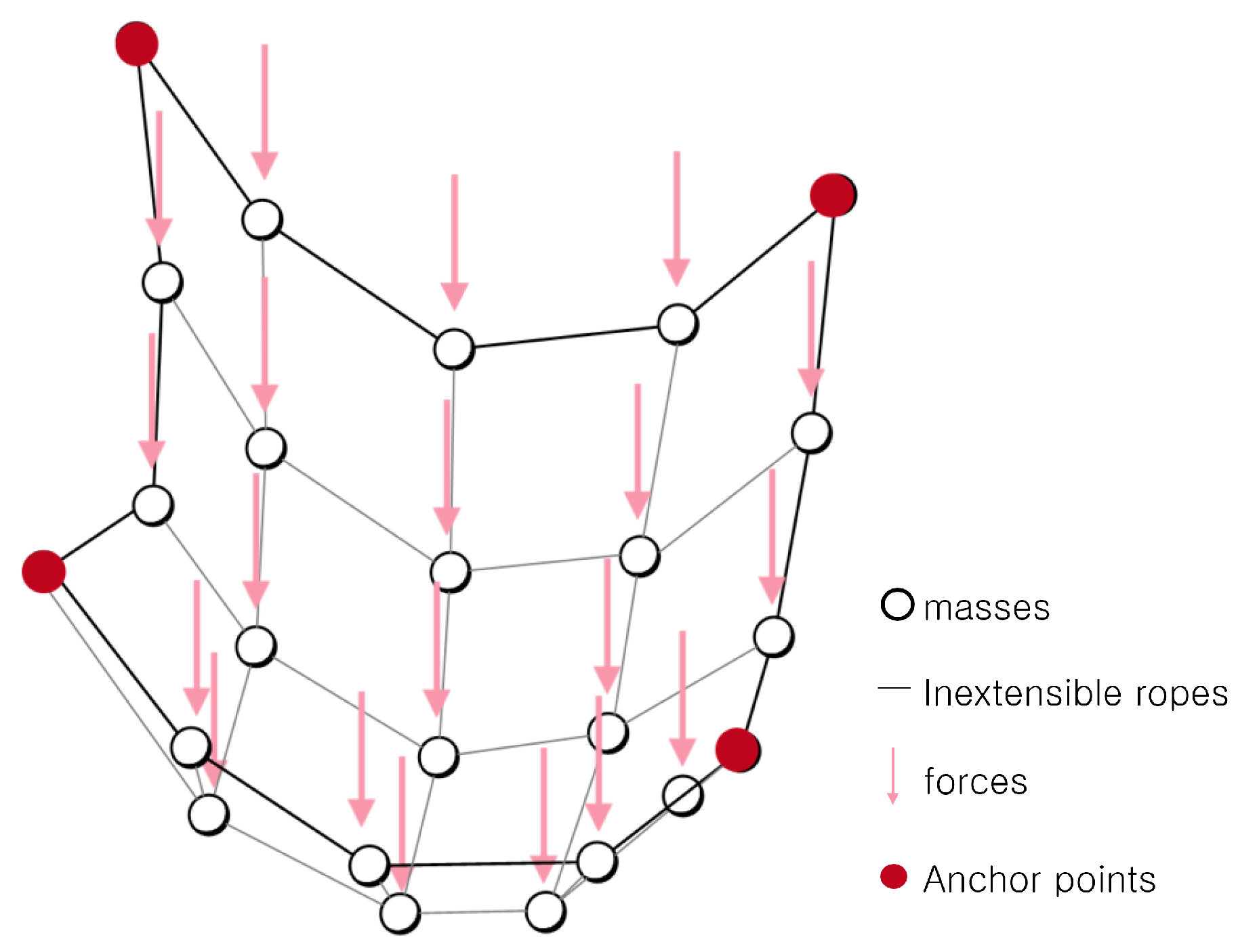
2.1. The Basic MRA Method

The Multibody Rope Approach (MRA) [26] is a methodology tailored for determining the shape of free-form gridshell structures. In this approach, the structural elements are represented as slack ropes, connecting the nodes under load. By employing a dynamic model of falling bodies (Figure 2) and applying D’Alembert’s principle, MRA iteratively calculates the equilibrium configuration of each node, achieving the optimal form of the gridshell structure.
The final shape of the hanging net represents the funicular configuration of the structure. In the equilibrium equations, there are no forces exerted by the ropes when the distance between the nodes is shorter than the fixed length of the rope l r o p e . By defining l as the distance between the two nodes and k as the rope axial stiffness, it is possible to express the forces F as:
F r o p e = 0 if l < l r o p e F r o p e = k ( l l r o p e ) if l l r o p e
The MRA technique typically assumes extremely high stiffness levels to minimize axial deformations. The equilibrium equation for any node i within the network can be expressed as follows:
R i = p i + j = 1 n i F r o p e , j i + F i I + F i I I = 0
In this equation, p i is the external load applied to the node. The vector R i represents the total force acting on node i, which is the sum of different forces, including the forces transmitted by the ropes that keep the node in position F r o p e , j i , the inertial force F i I I = u ¨ i = ( x ¨ i , y ¨ i , z ¨ i ) , and the damping force F i I = u ˙ i = ( x ˙ i , y ˙ i , z ˙ i ) .
The equilibrium equation can be extended to three spatial dimensions, resulting in the system of equations described by (3).
p i x + j = 1 n i ( x j x i ) l j i · F r o p e c i · x ˙ i m i · x ¨ i = 0 p i y + j = 1 n i ( y j y i ) l j i · F r o p e c i · y ˙ i m i · y ¨ i = 0 p i z + j = 1 n i ( z j z i ) l j i · F r o p e c i · z ˙ i m i · z ¨ i = 0
The natural frequency of the system is denoted as ω n , and critical damping is represented by ζ .
ω n = k m
ζ = c 2 ω n m
In this context, k is the stiffness, m is the mass, and c is the damping coefficient of the system. The natural frequency ω n is the frequency at which the system vibrates when no external forces are applied. The critical damping ζ , is the damping coefficient that enables the system to return to its equilibrium condition without any oscillations. Therefore, the equilibrium equation can be reformulated as follows:
u ¨ + 2 ω n ζ u ˙ = p i + j = 1 n i k · F r o p e , j i
The solution can be obtained as:
u ( t ) = C 1 e 2 ω n ζ + C 2 + C 3 2 ω n ζ t
The coefficients can be determined by considering the system initial conditions.
C 1 = 2 ω n ζ u ˙ ( t Δ t ) C 3 ( 2 ω n ζ ) 2
C 2 = ( 2 ω n ζ ) 2 u ( t Δ t ) + 2 ω n ζ u ˙ ( t Δ t ) C 3 ( 2 ω n ζ ) 2
C 3 = p i + j = 1 n i k · F r o p e , j i
The final solution can be computed through an iterative process, where the initial conditions for each time step are based on the solution obtained in the previous time step, as represented in Figure 3.
Starting from a very general base mesh, the provided method enables the determination of the funicular configuration for free-form gridshell constructions. The final shape is a function of the slack coefficient ρ , which is defined as the ratio between the initial distance between nodes and the desired rope length as follows:
ρ i j = l r o p e u i ( 0 ) u j ( 0 ) .
In the ultimate geometry, we can categorize structural elements into three groups based on their length. Those shorter than l r o p e are termed loose elements, those longer than l r o p e are referred to as over elements, and those with a length equal to l r o p e are designated as target elements.

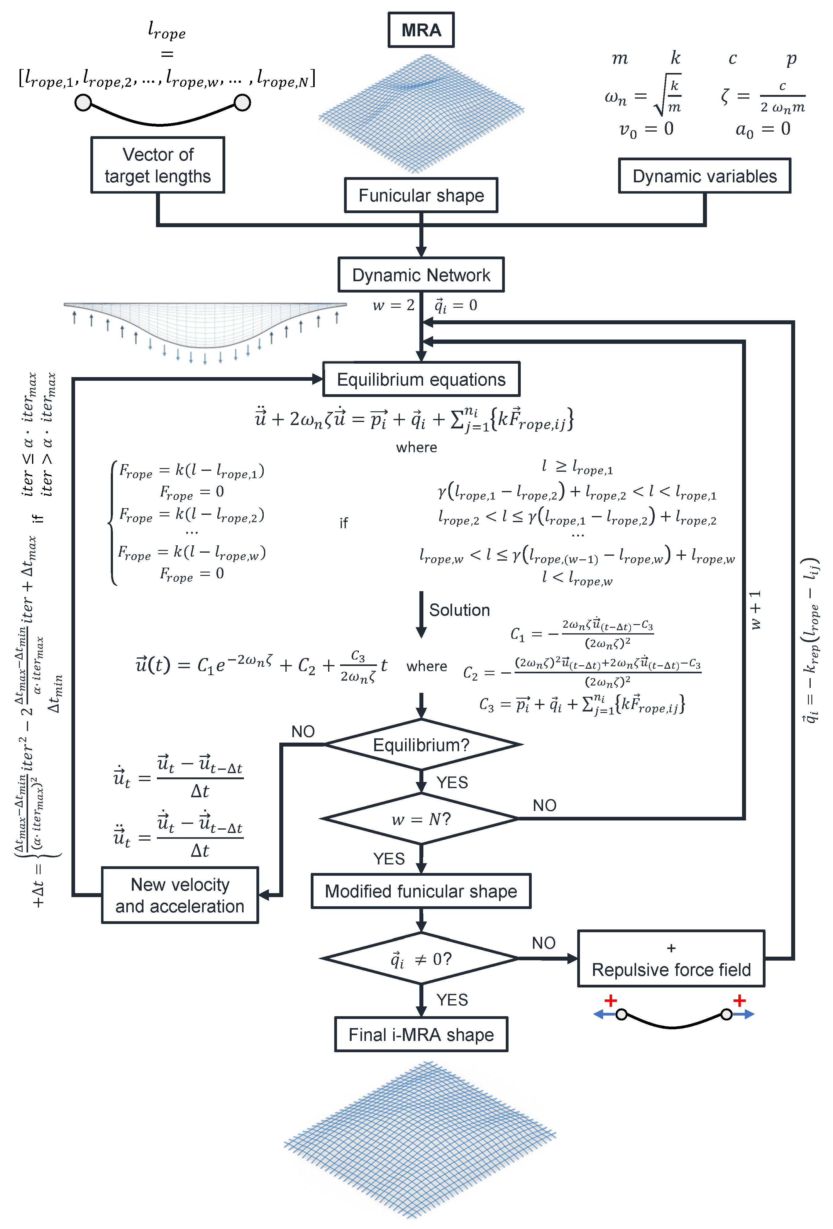
2.2. The Improved MRA Method

The preceding section introduced MRA as a method to identify the funicular geometric configuration for gridshell-type structures. The presented method enables the definition of an optimal geometric configuration to support the applied load during form-finding. However, the structural configuration obtained by this method is characterized by structural members of different lengths. This occurs because nodes in the generic hanging network dynamic problem are frequently connected by more than three ropes. Hence, the degrees of constraint represented by the ropes exceed the three translational degrees of freedom of the nodes. Consequently, the equilibrium configuration of the hanging net can be identified without having all the ropes under tension. Not all degrees of constraint need to be exploited to achieve equilibrium. In this configuration, the nodes connected by the slack ropes will be at a shorter distance than the target length defined by the MRA method. The corresponding structural elements will consequently exhibit a length different from the target one. The diverse lengths of structural elements pose a challenge in terms of the construction simplicity of gridshell structures. To minimize the diversity of structural components obtained through MRA, the multiple-order MRA method is employed. The new goal is to reduce the number of loose ropes in the final configuration. This is achieved by establishing new target lengths for loose ropes. The gridshell geometry is initially computed using traditional MRA with a target rope length of l r o p e , 1 . After achieving the final equilibrium arrangement, a new rope family with a shorter length is introduced ( l r o p e , 2 < l r o p e , 1 ), and the geometric configuration is iteratively recalculated.
F r o p e = 0 if l < l r o p e , 2 F r o p e = k ( l l r o p e , 2 ) if l r o p e , 2 < l ( l r o p e , 1 l r o p e , 2 ) + l r o p e , 2 F r o p e = 0 if γ ( l r o p e , 1 l r o p e , 2 ) + l r o p e , 2 < l < l r o p e , 1 F r o p e = k ( l l r o p e , 1 ) if l l r o p e , 1
.
In the equations, the γ coefficient can be adjusted to achieve various geometric configurations by favoring ropes of length l r o p e , 1 or l r o p e , 2 .
Once the new equilibrium configuration is achieved, if the updated geometry still includes loose ropes, the process continues iteratively by introducing additional target lengths. The use of this procedure results in a geometry in which structural elements are divided into a limited number of families, each characterized by a different length. MO-MRA enables the reduction of structural element types by grouping elements into families with varying lengths. It is also possible to further reduce the number of structural element types by combining MO-MRA with Repulsive Nodes MRA. This new method involves introducing a repulsive force field q between the nodes of the dynamical system. The introduction of the new repulsive forces involves adding a new component to the nodal forces, as depicted in Equation (13).
R i = p i + q i + j = 1 n i k · F r o p e , j i c i · v i m i · a i = 0
This force field, denoted as q , is introduced after achieving the final equilibrium configuration through the MO-MRA, necessitating a new iterative computation process to determine the updated equilibrium condition. The force field q is linearly proportional to the difference between the target length l r o p e and the distance between nodes connected by a slack rope l i j . To calculate the repulsive force field q , Equation (14) can be employed, where k r e p is the proportionality constant that relates the modulus of the repulsive force to the distance between nodes i and j.
q i = k r e p ( l r o p e l i j )
The addition of the repulsive force field seeks to separate the nodes of the hanging network by leading loose ropes to the desired length. This approach introduces geometric variations to the funicular configuration, reducing the diversity of structural elements. Indeed, the final equilibrium configuration obtained will be optimized to support the load composed of the forming load plus the repulsive force system. The geometry obtained will deviate from the optimal one obtained using the basic MRA method. For this reason, RN-MRA should be used with caution in cases where a small number of loose elements are present in the equilibrium condition. This enables a reduction in the variety of structural types without significant deviation from the optimal structural form.
In this section, the MO-MRA and RN-MRA methods have been introduced to enhance the basic MRA. These methods are proven to be effective in reducing the construction complexity of gridshell structures [37]. At the same time, their application requires iterative calculation of the equilibrium of a dynamic multibody system. The calculation can be computationally expensive. One method to speed up the calculation and reduce computational effort is to increase the time step Δ t used in the iterative calculation of the equilibrium configurations. The choice of parameters that control the dynamics of the system, such as damping, rope stiffness, and time step, can significantly affect the convergence of the system to an equilibrium position. If the time step is too large, the system can overshoot the equilibrium position, causing oscillations or even divergence. On the other hand, if the time step is too small, the convergence of the system can be slow, and the computational cost can be high. Therefore, selecting an appropriate time step is crucial to ensure that the system converges to an equilibrium position while minimizing computational time. Damping and rope stiffness can also play an important role in the convergence of the system. Increasing the damping coefficient can help reduce oscillations in the system, while increasing rope stiffness can help to stabilize the system. However, these parameters should be chosen carefully, as excessively high values can lead to convergence problems, such as slow convergence or even non-convergence. In summary, the choice of parameters that control the dynamics of the system should be carefully considered to ensure that the system converges to an equilibrium position while avoiding oscillations or divergence. A trade-off must be found between computational efficiency and system stability. A possible solution to fasten the equilibrium convergence without compromising the accuracy of the final solution involves using a dynamic time step. The idea is, to begin with, a large time step to enable the system to evolve quickly towards the equilibrium state and then gradually decrease the time step as the number of iterations increases until it reaches a sufficiently small value. This ensures a small time step in the final stages, which are crucial for accurate equilibrium configuration determination. There are various ways to vary the time interval law. A possibility is to implement a variable time step with a quadratic law, starting from a maximum value Δ t m a x to a minimum value Δ t m i n . Once Δ t m i n is reached after a certain number of iterations α · i t e r m a x (where α < 1 is a fraction of the maximum number of iterations i t e r m a x ), the time step remains constant at Δ t m i n until the final equilibrium is achieved. The relationship for the proposed time step variation law is given by Equation (15).
Δ t = Δ t m a x Δ t m i n ( α · i t e r m a x ) 2 i t e r 2 2 Δ t m a x Δ t m i n α · i t e r m a x i t e r + Δ t m a x if i t e r α · i t e r m a x Δ t = Δ t m i n if i t e r > α · i t e r m a x
In Figure 4, an example of the vertical variation of a node position along the z-coordinate with different time steps is represented. The graph provided in Figure 4 represents only the vertical variation of the selected node position. The same logic can be extended to positional variation along the other axes without any loss of generality. The graph was generated by limiting the maximum number of time steps to 10 5 and assuming that the calculation could be stopped if the node’s positions changed by less than 1 mm, with the final equilibrium configuration obtained with a tolerance of 1 mm. The graph illustrates that, in this particular example, selecting an insufficiently small time step, e.g., Δ t = 0.01 s, causes the system to oscillate indefinitely without ever reaching equilibrium. In contrast, selecting a sufficiently small time step, e.g., Δ t = 0.005 s, allows the system to reach equilibrium after approximately 80,000 iterations. However, selecting a small time step increases the computational cost, as the system must be computed for a greater number of iterations. To balance the trade-off between a time step that is large enough to decrease the number of iterations necessary for the system to reach final equilibrium while also being small enough to calculate the final equilibrium configuration accurately, a variable time step that varies over the iterations, as presented in Equation (15), is proposed. The variable time-step approach reduces the computational cost by approximately 25% while maintaining the millimeter accuracy required, as represented in Figure 5.
In conclusion, the i-MRA method represents a significant advancement over MRA, as it integrates techniques that not only optimize the structural geometry but also enhance the automation of the construction process. This improved approach incorporates three main techniques aimed at minimizing the number of structural elements with varying lengths.

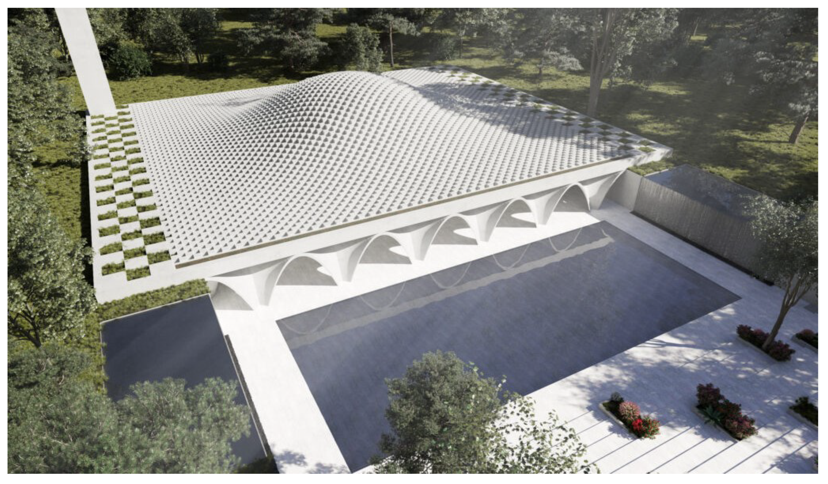
3. Geometry of the Dakar Mosque

Mosques hold a significant place in Islamic art and architecture, representing a synthesis of diverse cultural influences that have evolved over time [41]. With its unique design, the Dakar mosque serves as a cultural and social landmark aimed at fostering inclusivity and acceptance for people of all faiths [42]. The Islamic Cultural Center in Dakar, Senegal, which was designed by Wafai Architecture and the architectural firm Fragomeli & Partners, is depicted in Figure 1. The gridshell roof of the mosque is the case study that is discussed in this paper. In this paper, the focus of the structural analysis is the roof of the mosque, which takes the form of a steel gridshell resembling a desert dune, harmonizing with the surrounding environment. This roof, with its dimensions of 63 m × 56 m and free span, rests solely along its perimeter, eliminating the need for intermediate pillars. Architectural design imposes constraints on the structure geometry, one of which is the unique curve that distinguishes it from other types of vaulted constructions. The constraints have notable implications on structural behavior characteristics. Vulnerability is introduced by the roof’s inflection points, which results in a shape that is not ideal for a curved surface under vertical loads. To obtain the dynamic hanging net model subject to the load system shown in Figure 6, a parametric model of the structure was defined in the visual coding Grasshopper (Rhinoceros v7.0) [43]. A quadrangular flat parametric mesh was generated in the software. To simulate the roof, loads in opposite directions and with varying values were applied to the nodes of the generated mesh. The central nodes received upward-facing loads to facilitate the rise of the geometry, while the outermost nodes received downward-facing loads to induce the bending formation. The loading points are depicted in Figure 7, where red and green points, respectively, represent downward and upward loads.
The two presented form-finding methodologies were applied to attain a structural geometry of the gridshell roof. The idea is to define a shape that closely aligns with the architectural designer’s vision while also minimizing the diversity of structural element types. In this context, the utilization of a parametric model was crucial as it enabled the variation of the base mesh’s geometry and the regions of nodes loaded in two directions. These variations aimed to approach the desired geometry more effectively.
The application of the MRA produced the geometry depicted in Figure 8a, where approximately 60% of the structural elements had a length of 2.00 m. Taking advantage of the structural symmetry, this roof configuration could be constructed using only 19 types of structural elements. The only ropes that are tense in this setup are those that are attached to the central arch. This creates a structural hierarchy in which the central arch assumes the primary load-bearing role, and the remaining elements function as secondary components suspended from it.
Conversely, the i-MRA method yielded a more regular-shaped structure, as shown in Figure 8b. Notably, this approach resulted in a further reduction in the number of required structural element types, reducing it to just 8. There are no obvious structural hierarchies in this configuration because every structural element operates as a unit to support the loads. The i-MRA method achieved a more regular and architecturally aligned geometry where the structure resembles a shell-like form.

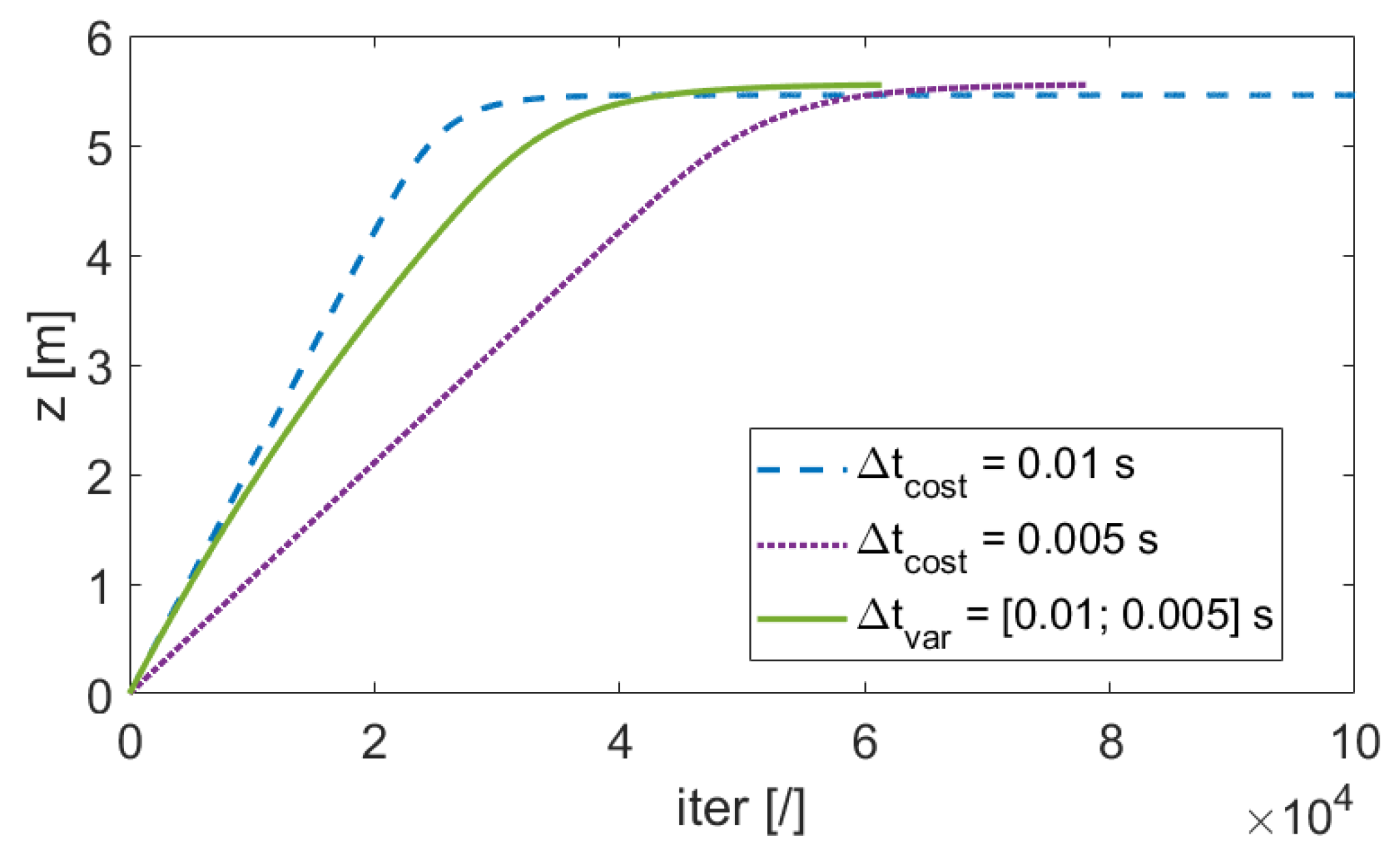
4. Numerical Results

The numerical results presented in this section, comparing the shapes obtained using the MRA and i-MRA methods, were obtained using the Diana(R) (Dianafea bv, The Netherlands) [44], specifically the Diana software v10.8 package.
The gridshell was modeled using quadratic three-node beam elements, which were fully constrained at the base support. The beam cross-section utilized a CHS 219.1 × 8.0 mm pipe profile, with the material chosen as grade S355 steel. The self-weight of the gridshell was automatically considered in the analysis.
To account for the additional weight of the glass-solar panel superstructures, concentrated masses were introduced at the intersections of the gridshell mesh. This approach enables the direct calculation of both static and dynamic effects associated with the added load.
Regarding wind loads, a preliminary simplified approach was adopted, assuming a uniform vertical negative pressure based on the anticipated wind velocity. While this simplified method serves as an initial assessment, a more refined analysis could be achieved by considering the local gradient of the shell or, ideally, through the utilization of numerical fluid-dynamic simulations.
The initial analyses were conducted to assess the structural response of the roof under the influence of dead load alone. The dead load encompasses the self-weight of the structural elements as well as the weight of non-structural permanent components, including the glass ceiling and photovoltaic panels. In this load case, the displacement of the structural elements was computed to evaluate their deflection behavior. In Figure 9, the total displacement resulting from dead weight is compared. It is worth noting that, for this particular load condition, the vertical displacements coincide closely with the overall displacements experienced by each node. This observation highlights the significant contribution of vertical displacement in governing the structural response under the influence of dead load.
It is evident that the structural behavior exhibits notable distinctions between the two cases, despite both demonstrating maximum displacements occurring at the inflection regions of the roof. These inflection areas represent structural weaknesses in terms of the response to vertical loading. Remarkably, the displacements are minimal near the supports and the central section of the structure, aligning with the expected behavior. This highlights the rigidity of the central dome-like section compared to the inflection zones. This confirms the well-established effectiveness of vaulted structures in supporting vertical loads, as evidenced by the larger displacements occurring in areas where the roof deviates further from the dome-like geometry.
The maximum displacement in the MRA shape exceeds double the corresponding maximum displacement observed in the improved i-MRA case. It is important to emphasize that even in the worst-case scenario, the maximum displacement remains below approximately 1/200th of the main roof span, which is equivalent to 63 m.
Figure 10 presents a comparison of the reaction forces exerted on the stiff support.
In the MRA gridshell, a distinct pattern is evident, showcasing the arching behavior along the X direction within a narrow central zone of the roof. Furthermore, the adjacent regions appear to be predominantly dependent on the central arch for support, as evidenced by the significantly lower reaction forces observed on the supports not directly influenced by the central arch. According to this hierarchy of load distribution, the central arch bears the majority of the vertical loads, with the remaining structure bearing a smaller share of the weight. Conversely, the i-MRA shape exhibits a more uniform distribution of support on the stiff structure. This reveals a clear bidirectional behavior of the overall structure, with arching mechanisms observed in both the X and Y directions.
Figure 11 illustrates the axial forces within the grid elements for both cases.
The observed structural behavior aligns with the expected outcomes based on the reaction forces. In the MRA case, it is evident that there are only two primary compressed ribs, positioned on either side of the central main arch in the X direction. The remaining sections of the structure, particularly in the Y direction, essentially rely on support from these two ribs. These different structural hierarchies are well visualized by the color-scaled graph, which also makes it easy to distinguish between the secondary elements that operate upon the compressed central arch and those that do not contribute to load transmission to the base supports.
In contrast, the optimal solution obtained through i-MRA reveals compressed arches present in both the X and Y directions. Additionally, the extent of tensile regions is significantly reduced compared to the MRA case.
The maximum compression axial force observed in the MRA case is nearly three times higher than the corresponding axial force in the i-MRA case. Similarly, the maximum tensile axial force in the MRA case is almost five times greater than the corresponding axial force in the i-MRA case.
Figure 12 displays the bending moment distribution within the grid elements for both cases.
It is important to note that, under the dead-weight load case, the gridshell does not exhibit complete freedom from moments. The bending moment should be close to zero in the structure since the form-finding techniques, especially the MRA, enable the computation of the funicular configuration with respect to the imposed loads. It is notable that in reality, this scenario does not occur, and structural elements are subjected to bending. The presence of bending moments in the structure has two different explanations. The first explanation is that the structural self-weight is treated as a distributed load on the structural elements. In contrast, the forming load used in the form-finding process was modeled as a concentrated load at the structural nodes. This implies that the geometry obtained is funicular with respect to the nodal load but not with respect to the distributed load. The second and more crucial reason is that, in this specific application case, the forming load has been modeled in a significantly different manner compared to the actual self-weight load. Indeed, the objective of the form-finding process was to achieve a geometry that closely aligns with the architectural design. For this purpose, an inverse load, compared to the actual gravitational load, was applied in the external area of the roof. Naturally, this approach facilitated the attainment of a geometry that closely resembled the desired architectural form but deviated from the funicular structural optimum.
In any case, the magnitude of bending moments results in being relatively limited. However, even in the case of bending moments, the i-MRA configuration appears to exhibit superior performance.
The maximum bending moment observed in the MRA case is approximately twice that of the corresponding bending moment in the i-MRA case.
Considering the static analyses for self-weight loading, it can be concluded that the tensioning of a greater number of structural elements in the i-MRA configuration leads to a more balanced and efficient distribution of forces. This results in a more optimal structural response and improved load-carrying capacity compared to the MRA configuration. The i-MRA method demonstrates its ability to reduce structural hierarchies and enhance the overall performance of the gridshell structure.
Figure 13 presents the axial stress diagrams resulting from the combined effects of dead weight and wind.
The observed patterns in the two models align with our previous observations.
However, it is important to acknowledge that the current loading scheme is oversimplified, representing a uniform vertical action at the gridshell nodes. Consequently, the influence of wind tends to offset the impact of the glass-solar panel superstructure.
It should be noted that a more realistic loading scheme would likely reveal more pronounced differences between the two models.
In Figure 14, a comparison is made between the two shapes in terms of modal frequencies and shapes.
The results obtained from the free-vibration analysis of the two optimized gridshells reveal similarities in terms of eigenfrequencies, indicating comparable dynamic characteristics. However, there are notable differences in the eigenshapes of the structures.
Specifically, the i-MRA exhibits a generalized frequency shift of approximately −0.1 Hz compared to the MRA case, as it is possible to observe in Table 1.
Finally, in Figure 15, a comparison is presented between the two shapes in terms of global instability, assessed through the critical load multiplier obtained via linear eigenvalue analysis.
The MRA shape demonstrates better performance than the i-MRA, exhibiting a higher critical multiplier. This result can be attributed to the presence of a more localized critical eigenshape in the MRA configuration.
However, it is important to note that further investigations are required to identify the complex postbuckling behavior of gridshell structures. The study of instability behavior of this structural typology should rely on more detailed geometrical nonlinear analyses [45,46,47]. These analyses should also consider factors such as initial geometrical imperfections [48] and the influence of horizontal loads, including seismic accelerations and wind effects.

5. Conclusions

This paper undertakes a thorough comparative analysis of two optimized solutions tailored for gridshell structures, with a specific focus on investigating the gridshell structure that functions as the roof for the Islamic Cultural Center situated in Dakar, Senegal. This case study serves as an illustration for the exploration of optimized solutions within the realm of gridshell design. The goal of the investigation was to assess the efficacy and performance of the two optimization methods employed, shedding light on their respective impacts on the structural configuration and overall functionality of the gridshell structure. The two different geometries of the structures were obtained using two different form-finding methodologies: the Multibody Rope Approach (MRA) and its improved version, the Improved Multibody Rope Approach (i-MRA). These form-finding techniques play a pivotal role in shaping structural configurations, and their comparative analysis provides valuable insights into the optimization potential and structural performance of gridshell designs. In particular, the MRA is a technique specifically designed to define the funicular shape of free-form gridshells. In contrast, the Improved Multibody Rope Approach (i-MRA) introduces geometric variations to the structure obtained through MRA application, aiming to enhance the constructability of the gridshell. This improvement seeks to address practical considerations in the construction process. In the specific case of the Dakar mosque roof, these methods were employed not only to find a shape that aligns with the architectural design but also to ensure practical feasibility, even if the resulting shape deviates from a strictly funicular form. The geometries obtained through MRA and i-MRA were subsequently subjected to a comparative analysis, evaluating their behavior under static loads. Two distinct load cases were examined in this study. The first case exclusively takes into account the application of dead loads, while the second case incorporates the influence of simplified wind action. Subsequently, a dynamic modal analysis of the two structures was conducted to identify differences in terms of modal frequencies and shapes. Finally, a linear buckling analysis was performed considering the dead-load conditions. This particular type of analysis allowed the comparison of the two solutions in terms of eigenshapes, shedding light on their respective stability and susceptibility to buckling phenomena under the applied dead load.
The outcomes of the analysis reveal that both solutions showcase satisfactory structural behavior, with the i-MRA solution demonstrating superior performance, especially under static loadings. In particular, the constraints introduced by the i-MRA resulted in a smoother and more regular structural configuration. The geometry obtained through i-MRA exhibited a bidirectional structural behavior, which demonstrated superior characteristics compared to the MRA solution characterized by a monodirectional arching behavior.
Although this aspect is worth deeper investigation, it can be argued that the introduction of multiple subsequent optimization iterations is beneficial for the obtained final configuration.
This research underscores the potential of the i-MRA as a viable and advantageous alternative to the MRA for gridshell design, particularly within the context of the Dakar mosque’s roof structure. The findings showcase not only the improved structural performance but also the enhanced constructability and aesthetic qualities achieved through the application of i-MRA.
Future investigations should focus on refining the node connections, aiming to optimize the design and enhance the overall structural performance of gridshell systems. This avenue of research holds promise for further advancements in gridshell design, providing opportunities for increased efficiency and effectiveness in their construction and functionality.

Author Contributions

Conceptualization, J.M. and A.M.B.; Methodology, J.M. and A.M.B.; Software, S.I.; Validation, S.I.; Formal analysis, J.M. and S.I.; Investigation, S.I.; Writing—original draft, J.M.; Writing—review & editing, S.I. and A.M.B.; Visualization, J.M. and S.I.; Supervision, S.I. and A.M.B.; Project administration, A.M.B. All authors have read and agreed to the published version of the manuscript.

Funding

This research received no external funding.

Data Availability Statement

The data presented in this study are available on request from the corresponding author. The data are not publicly available due to privacy.

Acknowledgments

The authors would like to express their gratitude to the Fragomeli & Partners architectural firm [35] for providing the case study for this research. The authors also acknowledge R. Rivoli for his contribution to the definition of the geometries utilized in this work.

Conflicts of Interest

The authors declare no conflict of interest.

References

  1. Melchiorre, J.; Manuello, A.; Marmo, F.; Adriaenssens, S.; Marano, G. Differential formulation and numerical solution for elastic arches with variable curvature and tapered cross-sections. Eur. J. Mech.-A/Solids 2023, 97, 104757. [Google Scholar] [CrossRef]
  2. Cucuzza, R.; Rosso, M.M.; Aloisio, A.; Melchiorre, J.; Giudice, M.L.; Marano, G.C. Size and shape optimization of a guyed mast structure under wind, ice and seismic loading. Appl. Sci. 2022, 12, 4875. [Google Scholar] [CrossRef]
  3. Abbate, E.; Invernizzi, S.; Spanò, A. HBIM parametric modelling from clouds to perform structural analyses based on finite elements: A case study on a parabolic concrete vault. Appl. Geomat. 2022, 14, 79–96. [Google Scholar] [CrossRef]
  4. Adriaenssens, S.; Block, P.; Veenendaal, D.; Williams, C. Shell Structures for Architecture: Form Finding and Optimization; Routledge: London, UK, 2014. [Google Scholar]
  5. Marano, G.C.; Rosso, M.M.; Melchiorre, J. Optimization as a Tool for Seismic Protection of Structures. In Proceedings of the World Conference on Seismic Isolation, Turin, Italy, 11–15 September 2022; Springer: Cham, Switzerland, 2022; pp. 100–113. [Google Scholar]
  6. Rosso, M.M.; Melchiorre, J.; Cucuzza, R.; Manuello, A.; Marano, G.C. Estimation of distribution algorithm for constrained optimization in structural design. In Proceedings of the WCCM-APCOM 2022, Yokohama, Japan, 31 July–5 August 2022; Volume 900. [Google Scholar]
  7. Happold, E. Philosophy of design with particular respect to buildings. In Structural Engineering: History and Development; CRC Press: Boca Raton, FL, USA, 1997. [Google Scholar]
  8. Addis, B.; Walker, D. Happold: The Confidence to Build; Taylor & Francis: Abingdon, UK, 2005. [Google Scholar]
  9. Otto, F.; Hennicke, J.; Matsushita, K. IL10 Gitterschalen; Institut für Leichte Flächentragwerke (IL): Stuttgart, Germany, 1974. [Google Scholar]
  10. Liddell, I. Frei Otto and the development of gridshells. Case Stud. Struct. Eng. 2015, 4, 39–49. [Google Scholar] [CrossRef]
  11. Sobek, W.; Blandini, L. The Mansueto Library–Notes on a glazed steel grid shell from design to construction. In Proceedings of the Challenging Glass Conference Proceedings, Delft, The Netherlands, 20–21 May 2010; Volume 2, pp. 179–186. [Google Scholar]
  12. Fritzsche, K.; van der Sluis, W.; Smits, E.; Bakker, J. Capital C, geometric optimization of a free-form steel gridshell towards planar quadrilateral glass units. In Proceedings of the Challenging Glass Conference Proceedings, Ghent, Belgium, 4 September 2020; Volume 7. [Google Scholar]
  13. Zhao, C.; Ma, J.; Du, S.; Gu, Y.; Zhou, Y. Mechanical properties of a novel joint of a single-layer aluminum-alloy combined lattice-shell structure. Mater. Tehnol. 2019, 53, 811–819. [Google Scholar] [CrossRef]
  14. Happold, E.; Wi, L. Timber Lattice Roof for the Mannheim Bundesgartenschau. 1975. Available online: https://pascal-francis.inist.fr/vibad/index.php?action=getRecordDetail&idt=PASCAL7589012232 (accessed on 20 February 2024).
  15. Harris, R. Design of timber gridded shell structures. Proc. Inst. Civ. Eng.-Struct. Build. 2011, 164, 105–116. [Google Scholar] [CrossRef]
  16. Collins, M.; Cosgrove, T. A Review of the State of the Art of Timber Gridshell Design and Construction. 2016. Available online: https://www.researchgate.net/profile/Matt-Collins-5/publication/307546000_A_Review_of_the_State_of_the_Art_of_Timber_Gridshell_Design_and_Construction/links/57c7f5e108aec24de04313f1/A-Review-of-the-State-of-the-Art-of-Timber-Gridshell-Design-and-Construction.pdf (accessed on 20 February 2024).
  17. Chilton, J.; Tang, G. Timber Gridshells: Architecture, Structure and Craft; Routledge: London, UK, 2016. [Google Scholar]
  18. Douthe, C.; Caron, J.F.; Baverel, O. Gridshell structures in glass fibre reinforced polymers. Constr. Build. Mater. 2010, 24, 1580–1589. [Google Scholar] [CrossRef]
  19. Baverel, O.; Caron, J.F.; Tayeb, F.; Du Peloux, L. Gridshells in composite materials: Construction of a 300 m2 forum for the solidays’ festival in Paris. Struct. Eng. Int. 2012, 22, 408–414. [Google Scholar] [CrossRef]
  20. D’Amico, B.; Kermani, A.; Zhang, H.; Pugnale, A.; Colabella, S.; Pone, S. Timber gridshells: Numerical simulation, design and construction of a full scale structure. In Structures; Elsevier: Amsterdam, The Netherlands, 2015; Volume 3, pp. 227–235. [Google Scholar]
  21. Cabrera Fausto, I.; Fenollosa Forner, E.J.; Llopis-Pulido, V.; Almerich-Chulia, A. Reliability associated with the use of building structural analysis and design software. Arch. e-J. Dissem. Dr. Res. Archit. 2018, 5, 13–37. [Google Scholar]
  22. Otter, J.R.H.; Cassell, A.C.; Hobbs, R.E.; Poisson. Dynamic relaxation. Proc. Inst. Civ. Eng. 1966, 35, 633–656. [Google Scholar] [CrossRef]
  23. Kilian, A.; Ochsendorf, J. Particle-spring systems for structural form finding. J. Int. Assoc. Shell Spat. Struct. 2005, 46, 77–84. [Google Scholar]
  24. Schek, H.J. The force density method for form finding and computation of general networks. Comput. Methods Appl. Mech. Eng. 1974, 3, 115–134. [Google Scholar] [CrossRef]
  25. Block, P.; Ochsendorf, J. Thrust network analysis: A new methodology for three-dimensional equilibrium. J. Int. Assoc. Shell Spat. Struct. 2007, 48, 167–173. [Google Scholar]
  26. Manuello, A. Multi-body rope approach for grid shells: Form-finding and imperfection sensitivity. Eng. Struct. 2020, 221, 111029. [Google Scholar] [CrossRef]
  27. Rian, I.M.; Sassone, M.; Asayama, S. From fractal geometry to architecture: Designing a grid-shell-like structure using the Takagi–Landsberg surface. Comput.-Aided Des. 2018, 98, 40–53. [Google Scholar] [CrossRef]
  28. Zhao, Z.; Yu, D.; Zhang, T.; Zhang, N.; Liu, H.; Liang, B.; Xian, L. Efficient form-finding algorithm for freeform grid structures based on inverse hanging method. J. Build. Eng. 2022, 46, 103746. [Google Scholar] [CrossRef]
  29. Huang, W.; Wu, C.; Hu, J.; Gao, W. Weaving structure: A bending-active gridshell for freeform fabrication. Autom. Constr. 2022, 136, 104184. [Google Scholar] [CrossRef]
  30. Invernizzi, S.; Manuello, A.; Ciaccio, F.; Nicola, P. Design of a modular exhibition structure with additive manufacturing of eco-sustainable materials. Curved Layer. Struct. 2021, 8, 196–209. [Google Scholar] [CrossRef]
  31. Douthe, C.; Mesnil, R.; Orts, H.; Baverel, O. Isoradial meshes: Covering elastic gridshells with planar facets. Autom. Constr. 2017, 83, 222–236. [Google Scholar] [CrossRef]
  32. Montagne, N.; Douthe, C.; Tellier, X.; Fivet, C.; Baverel, O. Discrete Voss surfaces: Designing geodesic gridshells with planar cladding panels. Autom. Constr. 2022, 140, 104200. [Google Scholar] [CrossRef]
  33. Seifi, H.; Javan, A.R.; Xu, S.; Zhao, Y.; Xie, Y.M. Design optimization and additive manufacturing of nodes in gridshell structures. Eng. Struct. 2018, 160, 161–170. [Google Scholar] [CrossRef]
  34. de Oliveira, I.M.; de Oliveira Pauletti, R.M.; Meneghetti, L.C. Connection system for gridshell structures using parametric modeling and digital fabrication. Autom. Constr. 2020, 109, 102996. [Google Scholar] [CrossRef]
  35. Fragomeli & Partners. Available online: https://fragomeliandpartners.com/ (accessed on 5 June 2023).
  36. Bertetto, A.M.; Riberi, F. Form-finding of pierced vaults and digital fabrication of scaled prototype. Curved Layer. Struct. 2021, 8, 210–224. [Google Scholar] [CrossRef]
  37. Manuello, A.; Melchiorre, J.; Marano, G.C. Improved Multi-Body Rope Approach for Free-form grid Shells. In Proceedings of the Italian Workshop on Shell and Spatial Structures (IWSS 2023), Turin, Italy, 26–28 June 2023. [Google Scholar]
  38. Melchiorre, J.; Soutiropoulos, S.; Manuello Bertetto, A.; Marano, G.C.; Marmo, F. Grid-Shell Multi-step Structural Optimization with Improved Multi-body Rope Approach and Multi-objective Genetic Algorithm. In Proceedings of the Italian Workshop on Shell and Spatial Structures, Turin, Italy, 26–28 June 2023; Springer: Cham, Switzerland, 2023; pp. 62–72. [Google Scholar]
  39. Manuello, A.; Melchiorre, J.; Sardone, L.; Marano, G.C. Multi-body Rope Approach for the Form-Finding of Shape Optimized Grid Shell Structures. In Proceedings of the 15th World Congress on Computational Mechanics, Yokohama, Japan, 31 July–5 August 2022. [Google Scholar]
  40. Cavaliere, I.; Fallacara, G.; Manuello Bertetto, A.; Melchiorre, J.; Marano, G.C. Multy Body Rope Approach and Funicular Prototype for a New Constructive System for Catenary Arches. In Proceedings of the Italian Workshop on Shell and Spatial Structures, Turin, Italy, 26–28 June 2023; Springer: Cham, Switzerland, 2023; pp. 259–268. [Google Scholar]
  41. Rugino, S. L’experiència del Sagrat a Través dels Llocs Rituals en L’arquitectura; ANUARI d’Arquitectura i Societat: València, Spain, 2021; pp. 198–214. [Google Scholar]
  42. Llana, D.G.A. La Cota Cero Como Lugar de Intercambio Comunitario; ANUARI d’Arquitectura i Societat: València, Spain, 2023; pp. 124–149. [Google Scholar]
  43. McNeel, R.; Associates. Rhinoceros 3D, Version 7.0; Robert McNeel & Associates: Seattle, WA, USA, 2023; Available online: https://www.rhino3d.com/ (accessed on 20 February 2024).
  44. Diana-FEA. Available online: https://dianafea.com/ (accessed on 3 June 2023).
  45. Melchiorre, J.; Bazzucchi, F.; Manuello Bertetto, A.; Marano, G.C. Postbuckling Echoes of iMRA Introduced Variation in Gridshells Mechanical Behaviour. In Proceedings of the Italian Workshop on Shell and Spatial Structures, Turin, Italy, 26–28 June 2023; Springer: Cham, Switzerland, 2023; pp. 379–389. [Google Scholar]
  46. Bazzucchi, F.; Manuello, A.; Carpinteri, A. Interaction between different instability phenomena in shallow roofing structures affected by geometrical imperfections. In Proceedings of the IASS Annual Symposia, International Association for Shell and Spatial Structures (IASS), Tokyo, Japan, 26–30 September 2016; Number 17. pp. 1–10. [Google Scholar]
  47. Bazzucchi, F.; Manuello, A.; Carpinteri, A. Interaction between snap-through and Eulerian instability in shallow structures. Int. J. Non-Linear Mech. 2017, 88, 11–20. [Google Scholar] [CrossRef]
  48. Bazzucchi, F.; Manuello, A.; Carpinteri, A. Instability load evaluation of shallow imperfection-sensitive structures by form and interaction parameters. Eur. J. Mech.-A/Solids 2017, 66, 201–211. [Google Scholar] [CrossRef]
Figure 1. Dakar Mosque (the image rendering was developed by Fragomeli & Partners).
Buildings 14 00598 g001
Figure 2. Dynamic model: the Multibody Rope Approach involves representing the structure as a network of ropes connecting nodal masses with concentrated loads.
Buildings 14 00598 g002
Figure 3. MRA workflow.
Buildings 14 00598 g003
Figure 4. Variation of the vertical position of the central node of Application 1 during the iterations, for different time steps Δ t .
Buildings 14 00598 g004
Figure 5. i-MRA workflow.
Buildings 14 00598 g005
Figure 6. Force field to obtain the imposed geometry.
Buildings 14 00598 g006
Figure 7. Loading points for gridshell form-finding: the green points are loaded in the upward direction, while the red ones are loaded in the downward direction.
Buildings 14 00598 g007
Figure 8. Geometries obtained with the form-finding techniques. (a) MRA, (b) i-MRA.
Buildings 14 00598 g008
Figure 9. Displacement due to dead loads. (a) MRA, (b) i-MRA.
Buildings 14 00598 g009
Figure 10. Bearing reactions due to self-weight. (a) MRA, (b) i-MRA.
Buildings 14 00598 g010
Figure 11. Axial force in the structural elements due to self-weight. (a) MRA, (b) i-MRA.
Buildings 14 00598 g011
Figure 12. Bending moment in the structural elements due to dead load. (a) MRA, (b) i-MRA.
Buildings 14 00598 g012
Figure 13. Axial force in the structural elements due to combination of self-weight and wind action. (a) MRA, (b) i-MRA.
Buildings 14 00598 g013
Figure 14. Mode 1 eigenshapes obtained with the dynamic modal analysis. (a) MRA, (b) i-MRA.
Buildings 14 00598 g014
Figure 15. Mode 1 eigenshapes obtained with linear buckling analysis. (a) MRA, (b) i-MRA.
Buildings 14 00598 g015
Table 1. Eigenfrequencies [Hz] obtained by the dynamic modal analysis.
ModeMRAi-MRAModeMRAi-MRA
11.030.91112.111.85
21.071.06122.212.03
31.081.14132.252.25
41.181.27142.522.26
51.811.52152.752.28
61.831.53162.822.45
71.881.64172.892.73
81.921.72182.962.74
92.051.81193.042.84
102.111.83203.062.85
Disclaimer/Publisher’s Note: The statements, opinions and data contained in all publications are solely those of the individual author(s) and contributor(s) and not of MDPI and/or the editor(s). MDPI and/or the editor(s) disclaim responsibility for any injury to people or property resulting from any ideas, methods, instructions or products referred to in the content.

