Article

Experimental and Numerical Analysis for Eccentricity Solution in Double-Layer Space Truss

by
Welington Vital
1,†,
Ramon Silva
1,*,†,
Luciano M. Bezerra
1,†,
Cynthia M. Oliveira
2,†,
Cleirton A. S. Freitas
3,† and
Jorge Bonilla
1,†
1
Department of Civil and Environmental Engineering, SG-12 Building, Darcy Ribeiro Campus, University of Brasilia, Brasilia 70910-900, DF, Brazil
2
Department of Civil Engineering, Federal District University Center—UDF, 704/904 Public Buildings Sector, South Wing Eq. 702/902, Brasilia 70390-045, DF, Brazil
3
Department of Civil Engineering, Federal University of Cariri, Juazeiro do Norte 63048-080, CE, Brazil
*
Author to whom correspondence should be addressed.
These authors contributed equally to this work.
Buildings 2024, 14(3), 608; https://doi.org/10.3390/buildings14030608
Submission received: 12 January 2024 / Revised: 13 February 2024 / Accepted: 20 February 2024 / Published: 26 February 2024
(This article belongs to the Section Building Structures)

Abstract

:
This paper shows an extensive study on the Typical Connections used in Double-Layer Space Truss. For this structural system, the ends of the bars are flattened to connect the bars. However, the flattening process results in a highly plastic stamping zone susceptible to warping with the appearance of two eccentricities, one of which causes rotation of the connection, with the presence of a bending moment with local rupture resulting in progressive collapse of the entire coverage system, as already evidenced in several countries. Therefore, eccentricity in this paper is studied and an analytical solution to the problem is presented through the use of a new device called a spacer. Furthermore, a preliminary study with complex numerical simulation was carried out with nonlinear analysis in ABAQUS were evaluated. For this study, nine space trusses were experimentally tested with reinforcement spacer in reduced trusses. After confirming the efficiency of the spacer proposal, another six space trusses were tested in the laboratory, this time, on a full-scale. In this study, two types of spacers were evaluated, one made of USI SAC 350 steel and another cheaper one made from recycled tires from heavy vehicles with multiple filaments of steel and nylon wires in the rubber layers. The two devices presented very close resistance capacity values, with a resistance gain of approximately 30% in relation to connections without reinforcement, with structural failure characterized by buckling of the bars. Finally, a numerical study of space trusses with spacers was developed. In practical design terms, from these FE simulations it was possible to determine the normal stresses for different spacers applied in the different modeled spans.

1. Introduction

The Double-Layer Space Truss (DLST) system became a common solution in the first decade of the 20th century. The development of the weld and of the MERO connections was concluded in 1942 [1]. There are several successful space trusses applications around exist all over the world, covering stadium and gymnasiums, public halls, exhibition centers, airplane hangars, gas station canopies, and many other buildings, incorporating features such as reasonable force transmission, high stiffness, large span, and easy installation [2]. Space trusses are made from different materials such as steel, aluminum, wood etc. Space trusses were copied from nature, the natural elements always seek to minimize stress and maximize strength in an efficient way, taking advantage of the load capacity of all members of the body [1,3,4]. The natural shapes have exceptional stiffness and use minimum materials to obtain the maximum structural advantage. The natural forms act in the direction of the least force [5]. Double-Layer Space Trusses comprise a set of members that are assembled to give different shapes, such as flat system, curved system, spherical system, and convex system [6,7]. The DLST is widely known for its square-on-square configuration system, and is also a type of system that possesses high structural redundancy and exceptional spatial ductility [8].
Furthermore, the DLST are reticulate lightweight structures in 3D geometric pattern made of bars or tubes interlocked at nodes. The reticulate tubes have several interconnections at nodes of the intersections of the tubes, such as top and bottom chords and diagonals. Space trusses are generally made with an assemblage of tetrahedral modules. There is a variety of node connections, some patented, some of the public domain. The simplest and most used connection in DLSTs trusses is named typical node, where flattened-end tubes are put together by bolts [1]. The design of space trusses is, generally, based on a nodal system that transmits only tensile and compression axial forces. The ideal node connection is not conceived to transmit a bending moment but just axial forces [9]. However, the previous collapses of DLSTs show that they are vulnerable to progressive collapse phenomenon. Under certain circumstances, a local failure in a connection can propagate throughout the structure and lead to occurring a brittle failure in the structure [10]. Previous research shows that most global collapses in space trusses DLST are most often related to member connection failure, which could be the reason why there are more than 250 space truss connection patents [11]. Nevertheless, the patented connections usually involve higher fabrication cost due to their complex geometry, and engineers resort frequently to simpler solutions with Typical Connections.
There are three alternatives’ systems of connections widely used. The first system is named typical node or Typical Connection (see Figure 1a,b). It is formed by flattened bars with the ends joined by a single bolt. The second system of Typical Connection is named Typical Connection with weld, designed with welded steel joints and the flattened bars are connected by bolts to a thin plate (see Figure 1c,d). In the third system of Typical Connection is named Typical Connection with weld and plate gusset (Figure 1e,f), the bar is not flattened but has notches at the ends to be engaged and welded in the gussets plates, and then screwed together in connection.
Therefore, in a real situation, the connection between bars or tubes must always be designed to minimize bending stresses, due to static and dynamic nodal actions [12]. However, this situation is usually not possible for some connections, especially the Typical Connection with tubes with flattened ends, as shown in Figure 1.
The Typical Connections, as they are an alternative solution with a lower cost, also present structural disadvantages compared with the patented connections [13,14]. Among the main problems observed in previous research, are: (a) a lack of international standards to consider the flattening of bars, due to the complex behavior of residual stresses caused in the bar stamping process, resulting in a zone of the tube highly susceptible to plastification. This variation can cause significant reductions in the resistance to compression of the bar compared to the values of designs standards, which consider only a constant section along the length of the bar. Therefore, high concentrations of stress in the flattened regions are not considered. (b) Regarding the global behavior of space trusses whose nodes are formed by super-position of bars with flattened ends; these can present reduced values of load carrying capacity [15].
There are high concentrations of stress on the nodal region, separation and slip between bars, which can sensibly increase the loss of bearing capacity with the emergence of bending moment [4,11,16]. (c) The eccentricities in the connections can cause increases of stress for a reduced nodal stiffness [17,18]. Another characteristic worth emphasizing refers to the collapse of special trusses with typical joints, which occurs because of the collapse of the connection with inefficient use of the bar’s strength capability [19]. (d) Since the sudden collapse of the Hartford Coliseum space truss, in 1978, a large number of theoretical and experimental studies have been carried out. Several studies have shown the collapse was due to local instability of compressed members with eccentricity, resulting in flexo-compression at the connection [4,11].
In this context, this paper presents a study on the solution of eccentricity in Typical Connections, the evolution of the research is presented, demonstrating how it was possible to solve the rotation of the Typical Connection using spacers. In this initial study, nine space trusses DLSTs square were built in carbon steel, with a length and width of 2.00 m and a height of 0.70 m with four pyramidal modules. After validating the proposed solution for correcting eccentricity in the smaller-scale truss using spacers, six more full-scale spatial trusses were then built, measuring 8.64 m long by 5.76 m wide and 1.06 m high, with a total of 24 pyramidal modules, where the spacers in eccentricity correction and the global failure mechanism of the DLST were effectively evaluated. Finally, a nonlinear numerical model in ABAQUS was developed and validated to evaluate the stress field in the different spacers used experimentally.

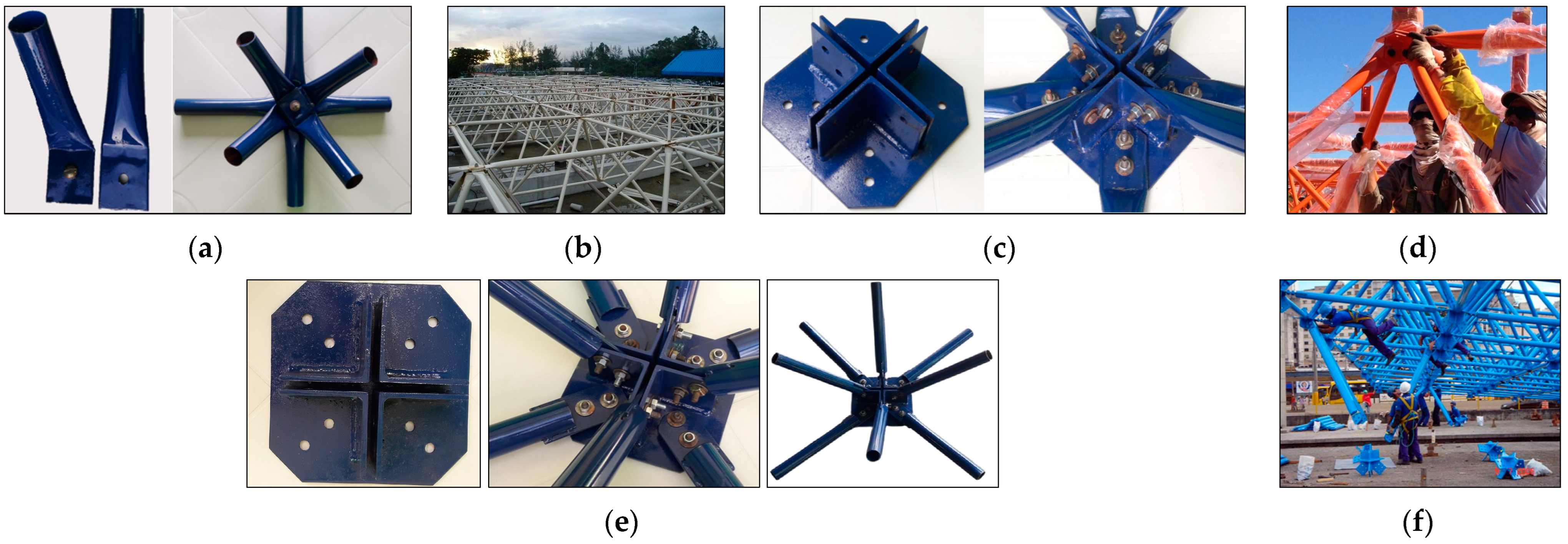
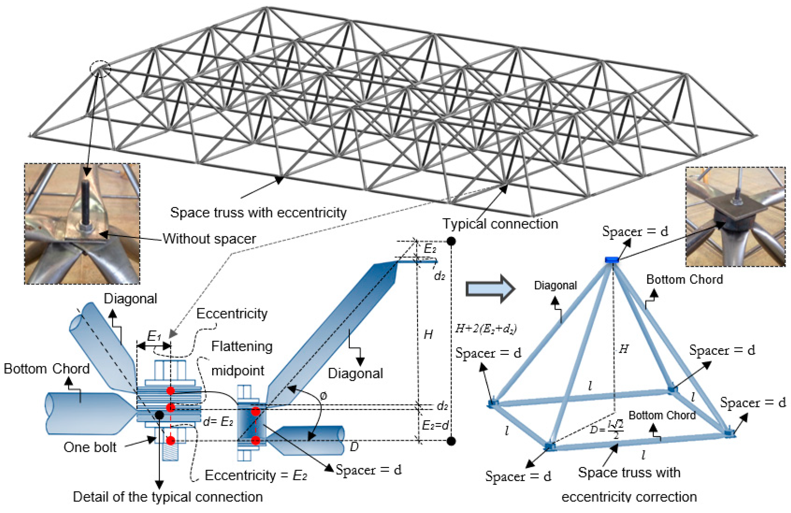
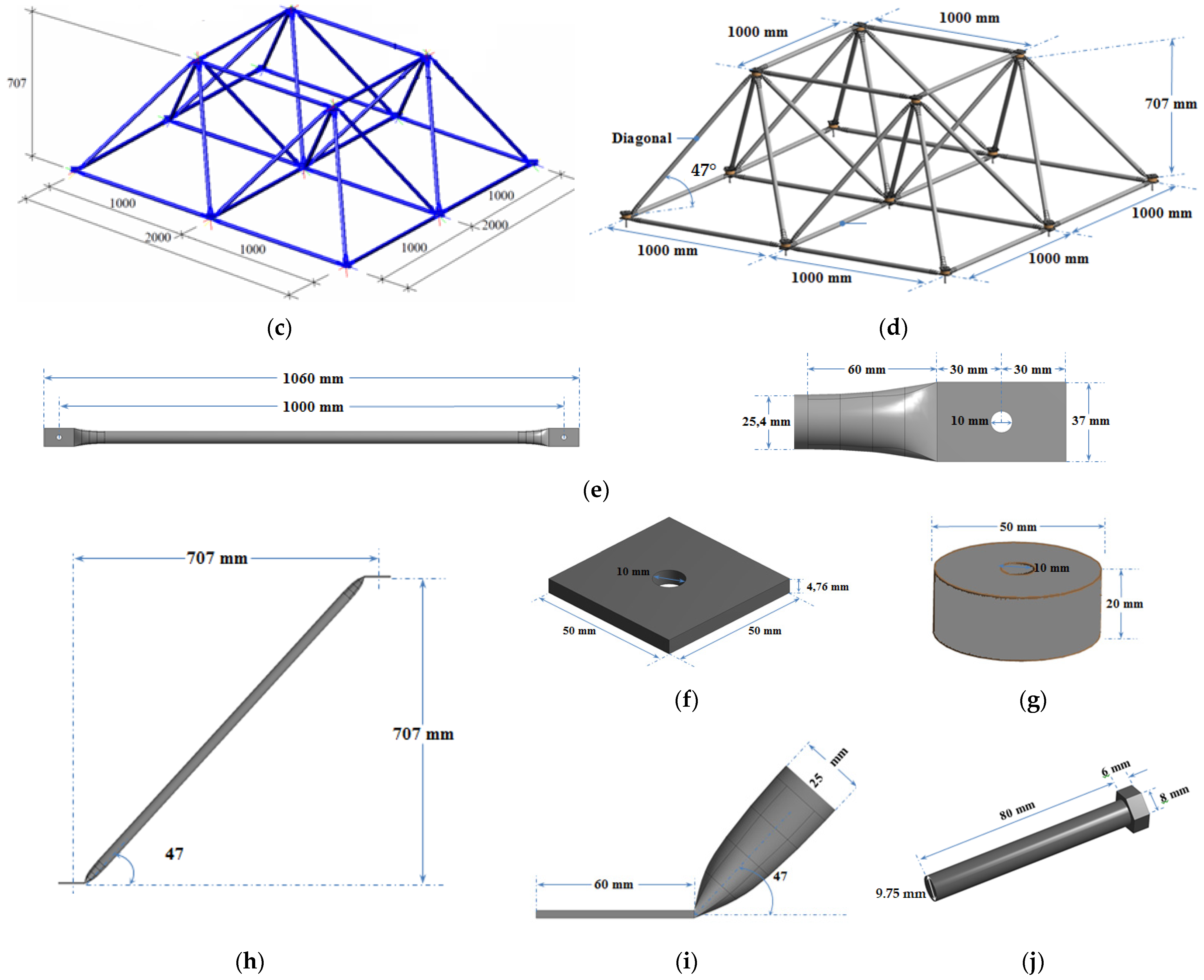
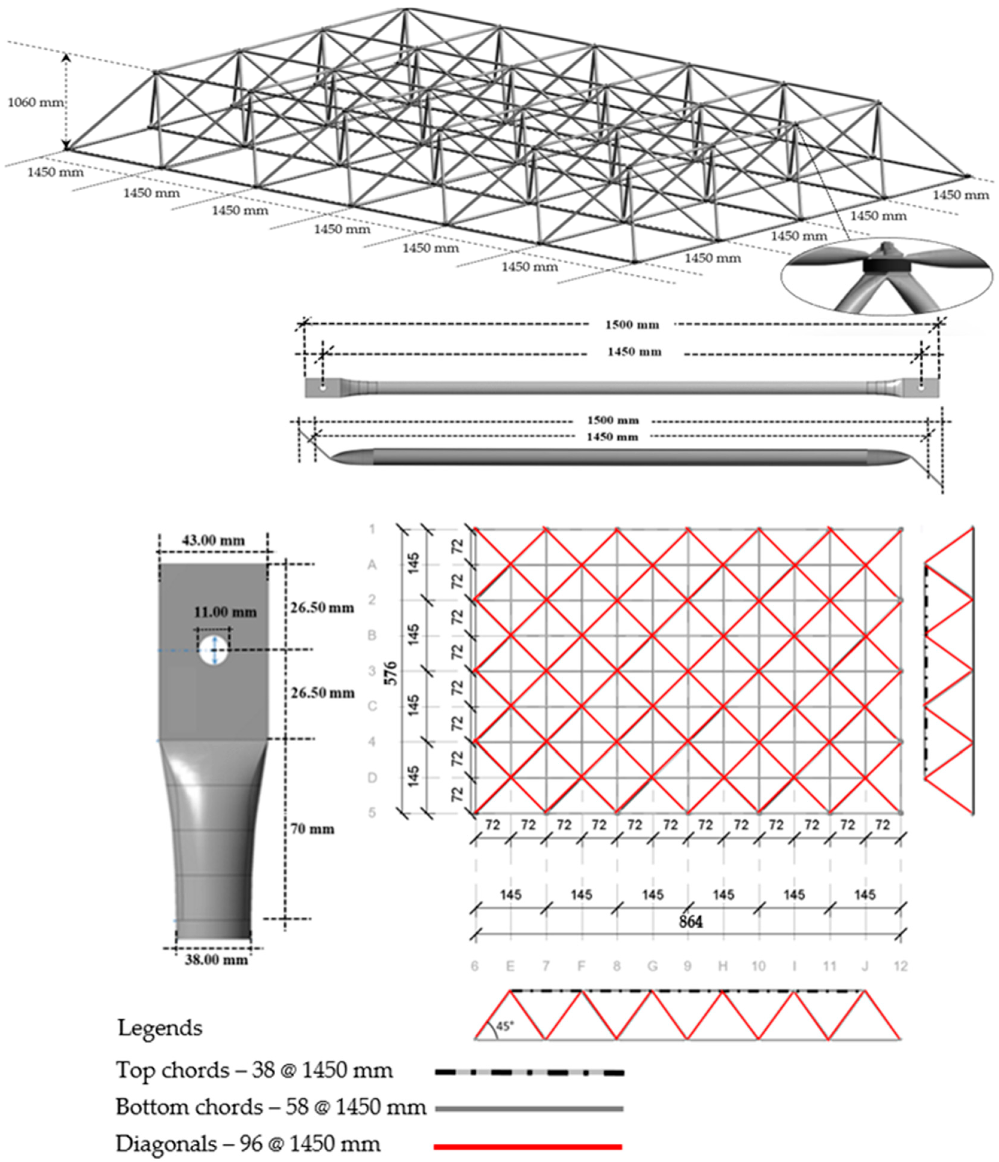
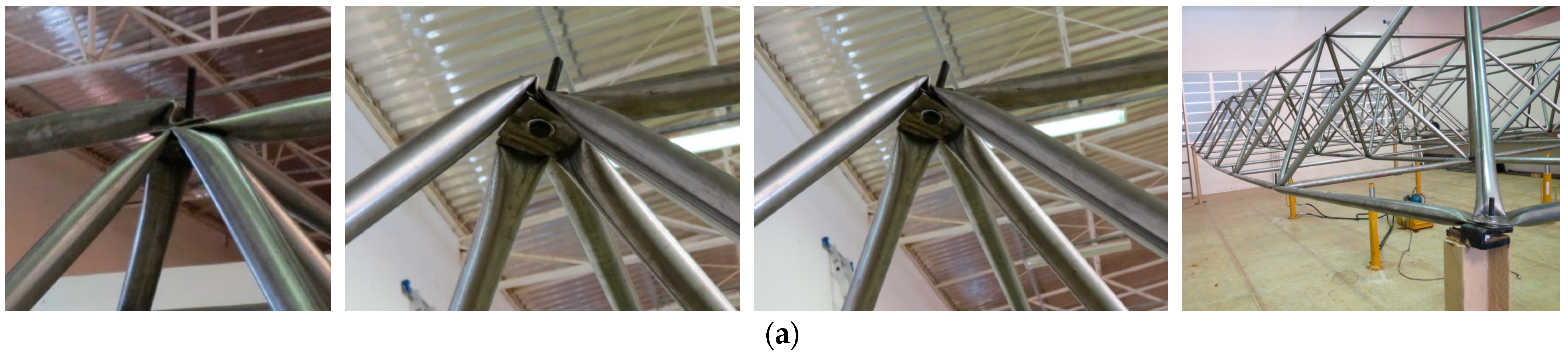
2. Geometric Determination of Eccentricity in Typical Connection Applied DLST

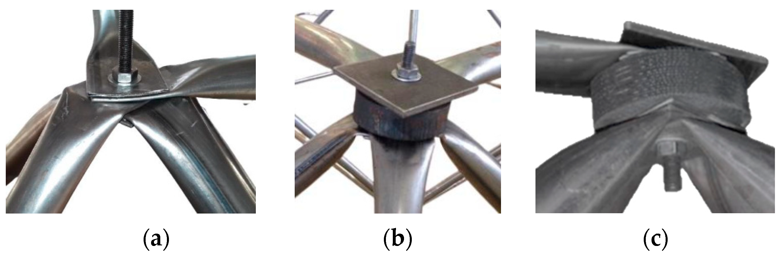
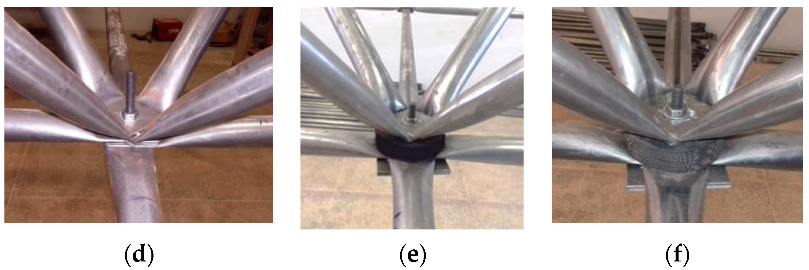
2.1. Eccentricity Solution with Spacer

Many failures occurred in steel structures [20,21,22,23,24,25,26], in the case of space trusses DLST this is related to eccentricity in the Typical Connections that were results of the tubes with flattened ends [4,11]. The tubes are put together with a single bolt placed at the middle of the nodes. This configuration produces the mismatch of lines passing through the center of gravity of truss diagonals and chords, as shown in Figure 2a. Consequently, it generates eccentricities, with the application of loads, and there are bending moments at the connections. This situation differs from the idealized node imagined for the truss in the design process. A proposal was developed to solve this eccentricity in the connection shown in Figure 2b with use of the spacer.
The proposal to use the spacer between the two chords and the diagonals of the space truss DLST managed to correct the eccentricity that causes rotation of the Typical Connection. Therewith, point B approaches point A and geometrically corrects the eccentricity E2 (see Figure 2a) with a spacer d (see Figure 2b). Therefore, the height of the spacer was obtained using the triangle similarity relation, as presented in Figure 3, where the nodal geometric adjustment of the Typical Connection was obtained from the application of a spacer element between the truss bars [4].
The eccentricities in the Typical Connections are results of the tubes with flattened ends. The tubes are put together with a single bolt placed at the middle of the nodes. This configuration produces the mismatch of lines passing through the center of gravity of truss diagonals and chords, as shown in Figure 2a. Consequently, it generates eccentricities, with the application of loads, causing bending moments at the connections. This situation differs from the idealized node imagined for the truss in the design process. The proposal to use the spacer between the chords and diagonals of the space truss managed to correct the eccentricity that causes rotation of the Typical Connection.
d = H E 1 D 2 E 1 ( 8 t )
where: d is the length of the eccentricity, given as a function of the dimension of the pyramidal module, which represents the distance (node to node centers) of the bottom chords. H is the height (node to node centers) of the space truss, E1 is the stamping eccentricity generated, and t represents the thickness of the tube. The eccentricity E1 is intrinsic to the stamping of the end-flattened tubes and cannot be corrected (Figure 2). In this equation, equal thicknesses is considered for the tubes of the diagonals and chords.

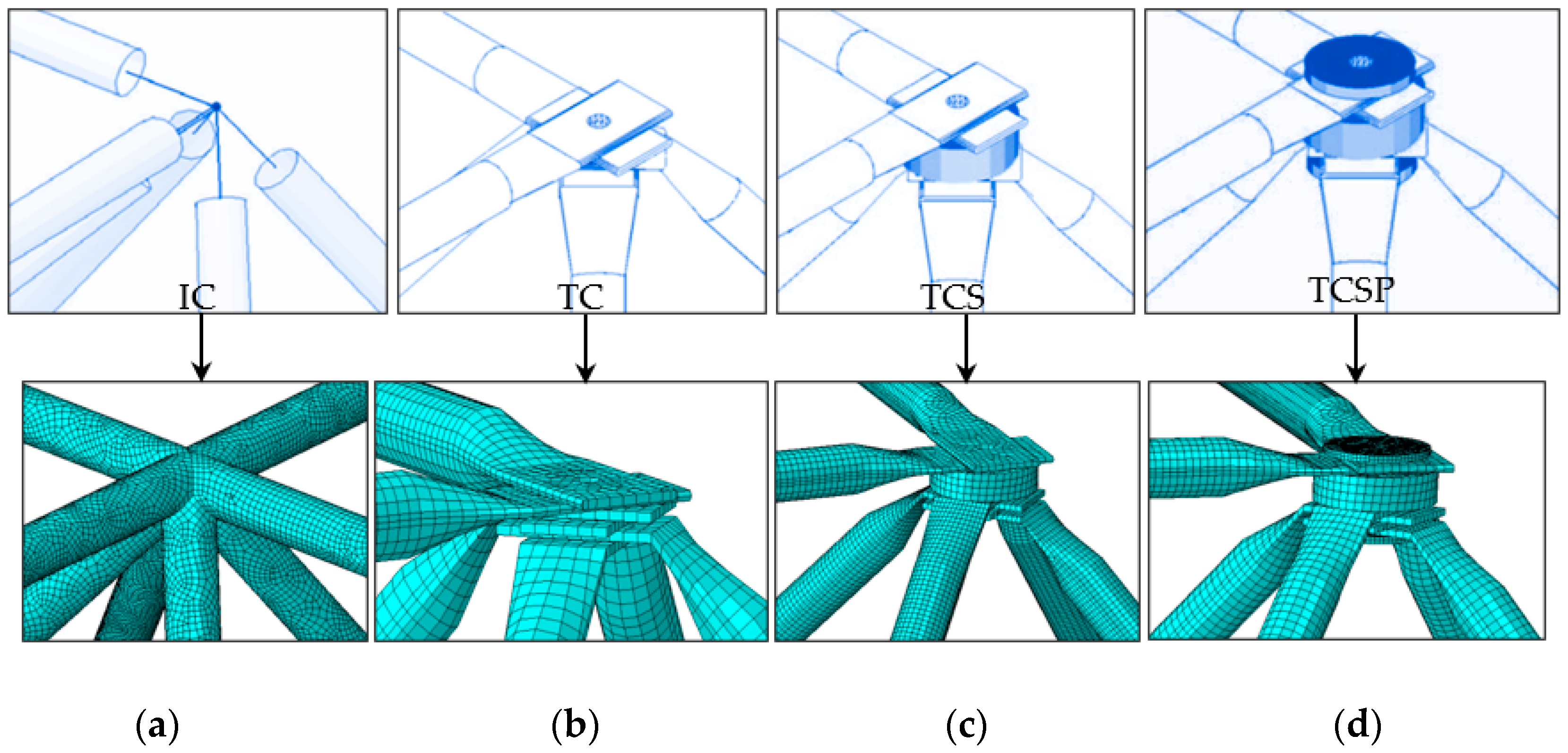
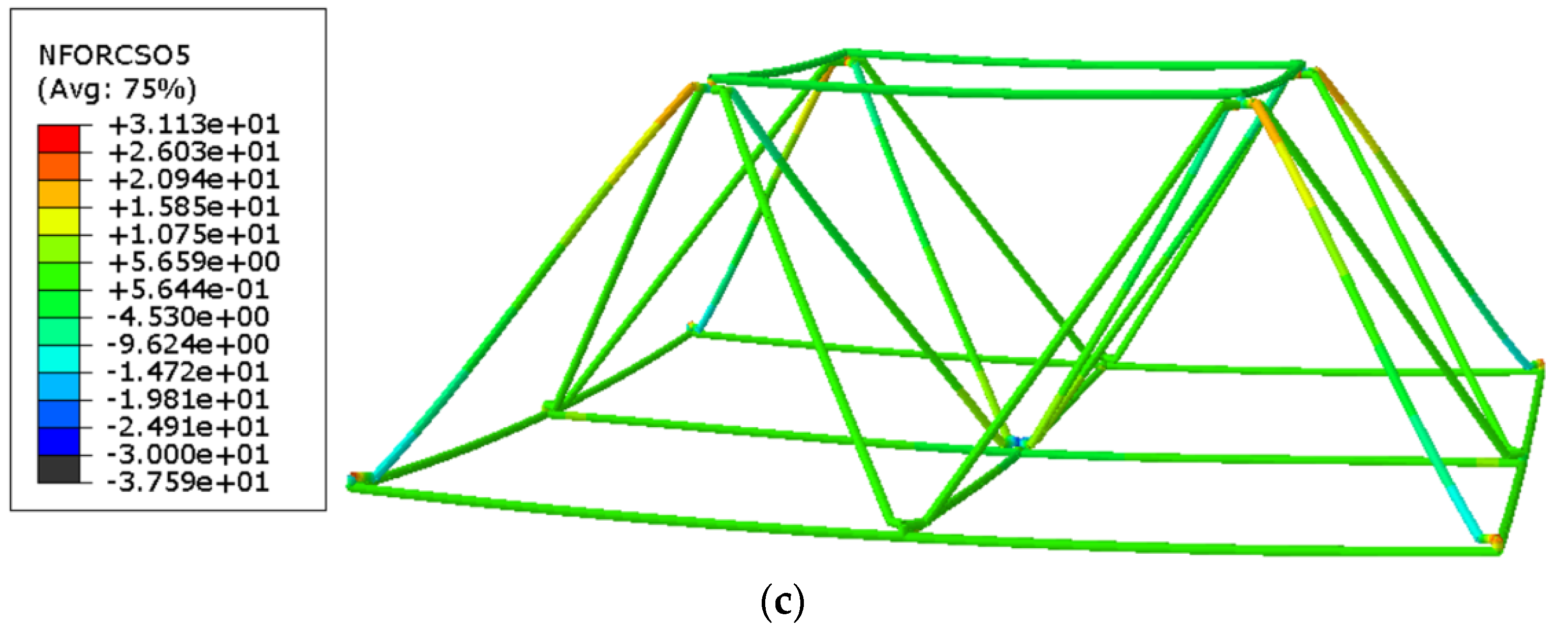
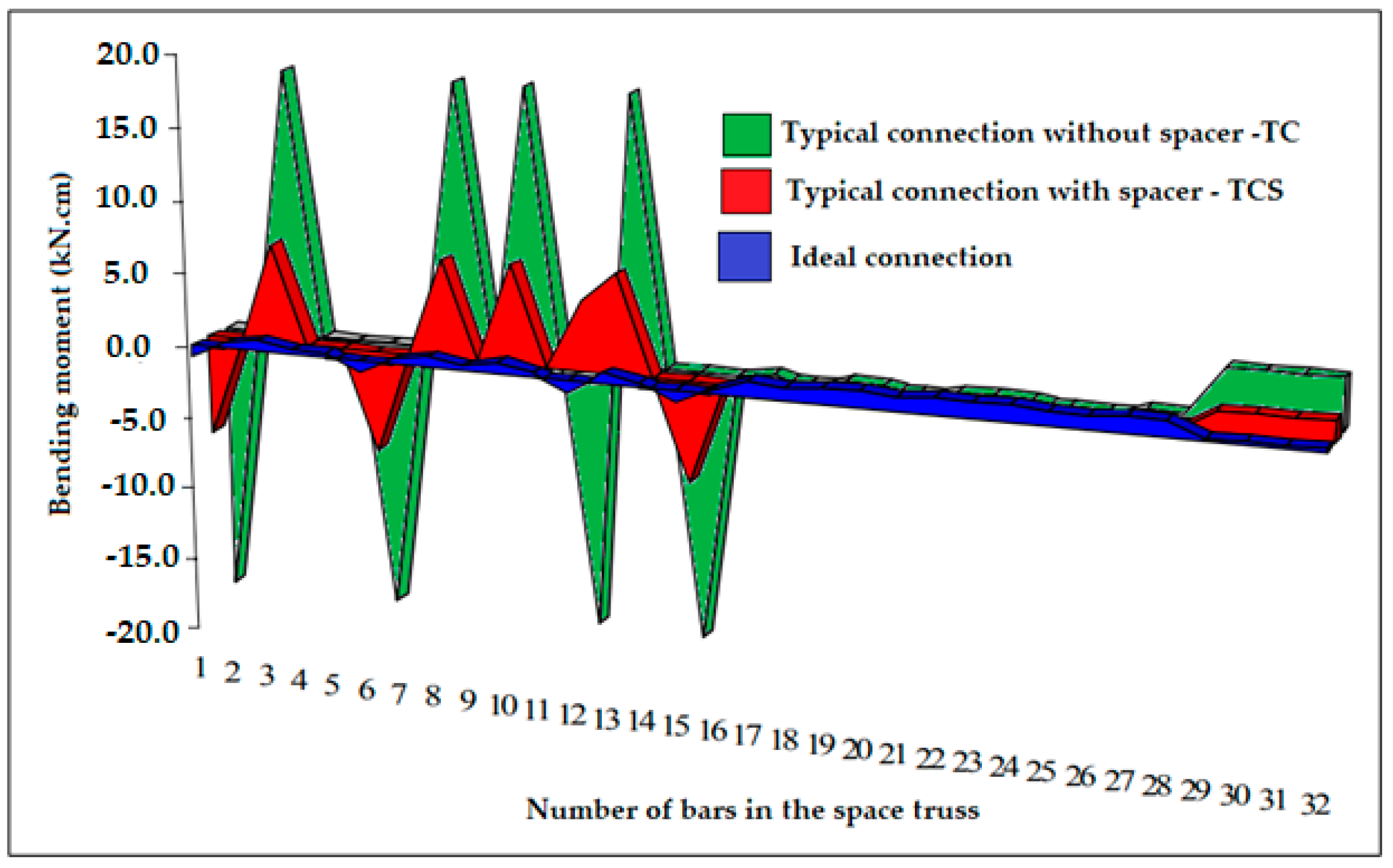
2.2. Preliminary Numerical Simulation with Typical Connections

Several studies have applied non-linear analysis to structural parts under compression, either with BP–Garson analysis that combines neural network and Garson algorithm [27], or also through iterative transient analytical analysis. In this paper, the numerical study focuses on the use of the ABAQUS program with FE simulation. A preliminary study was carried out for comparing four spatial truss connection configurations, simulated in FE with a non-linear model in ABAQUS [28] to analyze the stress field in the connections. The first numerical model was using the Ideal Connection (IC) without eccentricity, which considers a space truss of connections with bars perfectly centered at the joint, as shown in Figure 4a. The second model was developed through the Typical Connection (TC) system, which consists of elements with flattened ends with an eccentric connection at the node, as shown in Figure 4b. Conversely, the third model has a spacer element in the Typical Connection, comprising a structural system consisting of elements with flattened ends and a spacer inserted between the diagonals and the chord of the top chord (TCS). This model makes the eccentricity correction, as shown in Figure 4c. Finally, the fourth model was simulated using a Typical Connection with flattened bars at the ends, using a spacer between the diagonal bars and chords. Furthermore, a reinforcement circular plate was used at the ends of the connection to increase the stiffness of the set, as shown in Figure 4d with the acronym (TCSP).
The four 3D models of DLSTs space trusses simulated in ABAQUS [28] used carbon steel tubes with a diameter of 25 mm and a thickness of 1.50 mm with a steel yield stress of 285 MPa. It included an elastoplastic analysis with isotropic hardening in a bilinear condition, with an ultimate stress of 295 MPa. The stress–strain curve of steel was made of ideal elastic–plastic model and von Mises yield criterion is adopted. The performance parameters of the material are determined according to the tensile results of the standard sample in Table 1 associated with the experimental test. The boundary conditions of the finite element model are basically consistent with those of test [29]. The TIE contact was applied between the bars through the ABAQUS library through the interaction algorithm. The analysis of force steps was performed with the static RIKS algorithm [30,31]. A prescribed displacement of 10.00 mm was imposed on all models at the central connection. The finite element mesh in all models was S4R: A4, with a doubly thin curved node, used a reduced integration, with hourglass control, the maximum element size was 5.00 mm with a total of 297,856 finite elements by space truss DLST. Figure 5 shows the space truss model with Typical Connection (model b) with boundary conditions.
In order to determine the properties of materials used for the test components, the test pieces are made according to the following Figure 6, according to the requirements of GB/T 228.1-2010 and ASTM A36/36M [29,32,33]. In these tests, there are three main cross sections used for the test pieces. The yield strength fy, ultimate tensile strength fu and elongation of the material used in the test pieces, as shown in Table 1.
Initially, the flattened bar was cut into seven sections so that it could be drawn in each of the sections in REVIT to assemble the bar in the numerical model. After drawing all the chord bars and diagonals in REVIT in a solid 3D element, the model was exported to a SAT file to be imported into the ABAQUS library. In the ABAQUS Interaction library, the CONSTRAINT MANAGER algorithm was used to create TIE contact between all surfaces of the model, as shown in Figure 7.
To complete the preliminary study, another model was carried out with bar elements in ABAQUS, with three types of connections, to evaluate the bending moment in the connections shown in Figure 4 IC, TC, and TCPS, and also to verify that Typical Connections with spacers reduce the bending moments at the nodes.

2.3. Preliminary Numerical Simulation Results

The results of the numerical simulation of the four spatial trusses demonstrated that the Ideal Connection (IC) presents a flow of concentrated stress between the bars that is smaller than in other models, as it does not need to flatten the bar at the node. However, the complexity of construct trusses with this type of connection practically makes their construction impossible, not only due to the difficulty in carrying out welding, but also due to the execution of cuts in the steel tube to assemble the bars. As expected, the failure of the second special truss using the Typical Connection occurred locally in the connection with excessive distortions of the diagonal ends, without the occurrence of buckling in the bar, i.e., the bars failed due to the bending moment in the connection and to eccentricity and not due to global buckling. In the third truss model using the spacer to correct the eccentricity, the global collapse occurred abruptly, characterized by the loss of resistance to the load applied in the steps of the prescribed displacement, with the occurrence of plastification of the top chord, in the zone of flattening of the bar. Thus, the global collapse of the truss initially came from the local collapse of the end of the upper chord with the local failure. However, there were no further rotations in the connection, demonstrating that the spacer reduced the presence of bending moment, and prevented local rotation of the entire connection. Finally, in the fourth model was used an overlapping plate together to the spacer, in this case, there was a global rupture of the truss and avoided local failure in the bar stamping zone, presenting the best result of the entire simulation. Figure 8 presents all the results of the FE models.
The preliminary study was completed with the results of forces and moments in the three types of connections, IC, TC, and TCS. For this, the analysis in ABAQUS is presented in Figure 9, where the spatial truss was simulated using beam element with the output variable NFORCSO, that is, nodal forces in beam section orientation. The resistant force of the truss with IC presented a result of 34.94 kN, while the truss with TC, presented the lowest result, with a value of 23.52 kN. Conversely, the truss with spacer TCS obtained a result of 31.13 kN, a value very next to the IC, with less distortion than the TC.
Numerical simulations of FE space trusses with shell elements type S4R: A4 demonstrated the need to use both the spacer and the overlapping plate to increase the resistant capacity of the truss and reduce stress concentration and avoid rotations due to eccentricity caused due to the flattening of the bars. In the three trusses with bar elements, it was shown that a Typical Connection without a spacer significantly increases the rotation in the connection and, in addition, presents a lower resistance of around 37% in relation to the other two trusses. The bending moment in the three connections are presented in Figure 10.

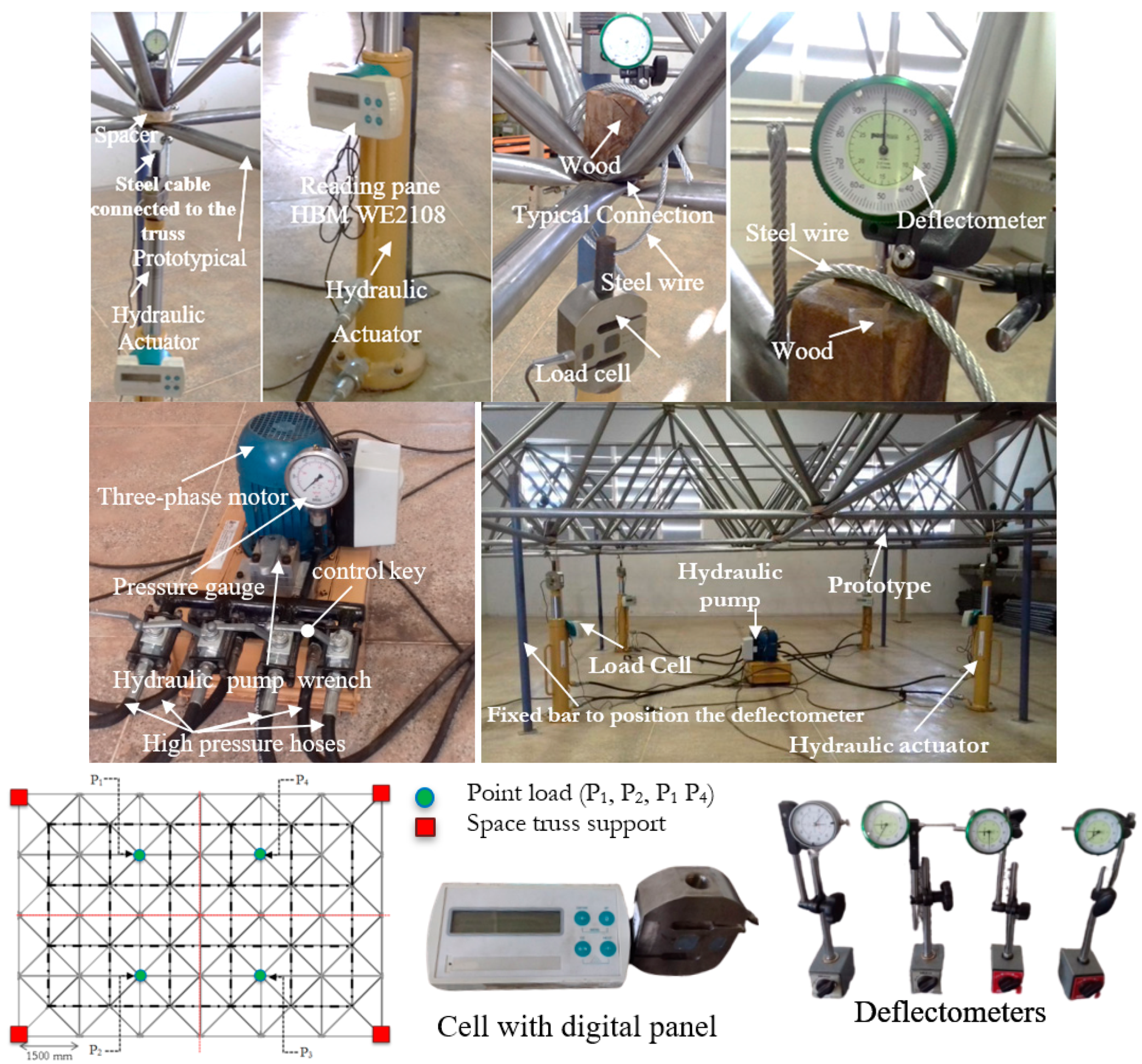
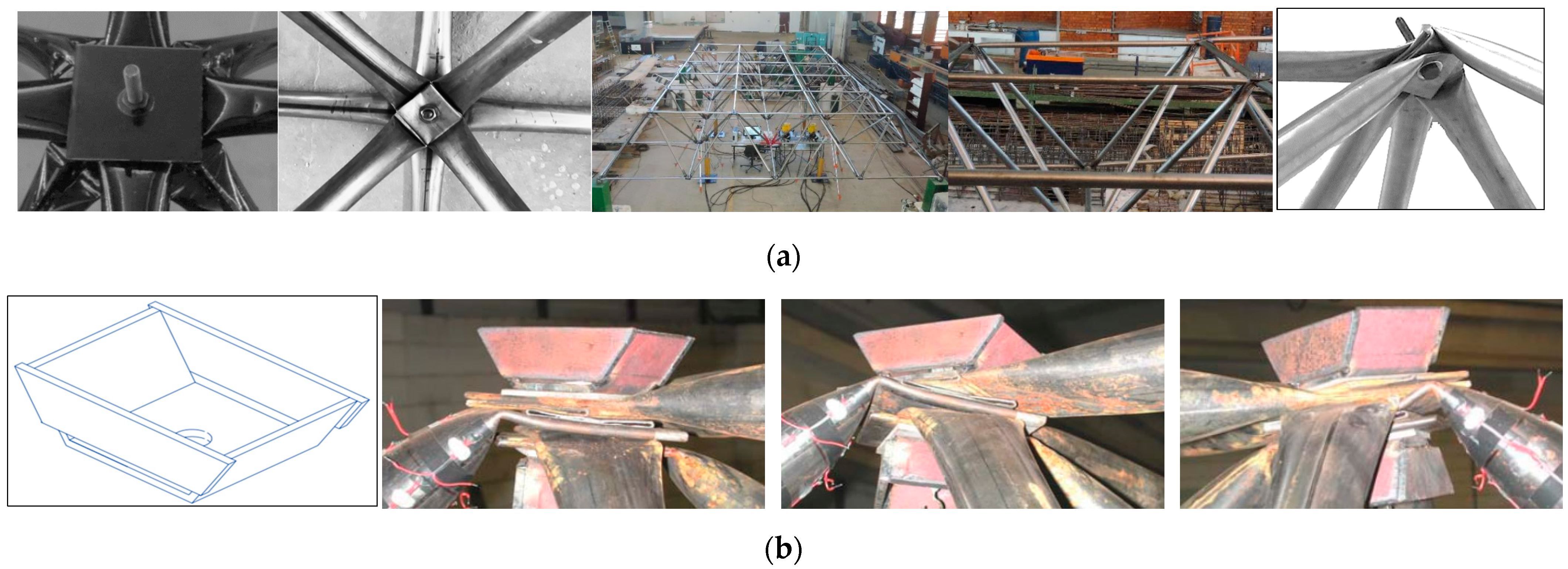
3. Experimental Program

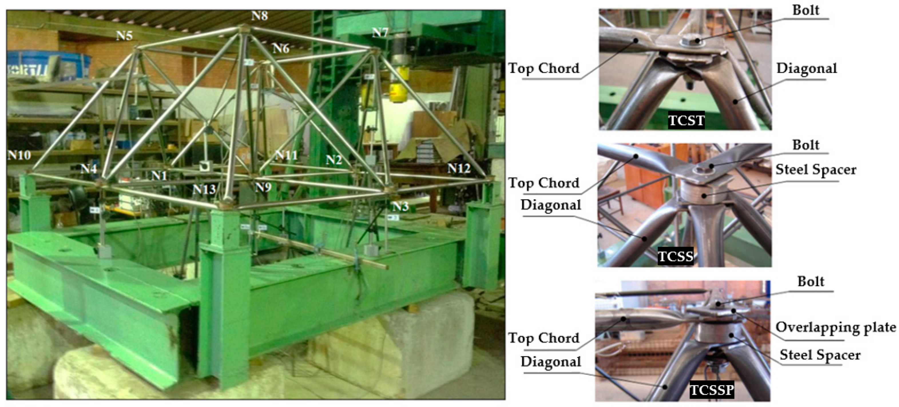
3.1. Testing on Reduced Space Trusses

Initially, to evaluate the behavior of space trusses, nine prototypes were built in the Structure Laboratory of the University of Brasilia (LASBEST-UnB), with small trusses measuring 2.00 m by 2.00 m, with a height of 0.70 m. The objective was to evaluate the effect of the correction of the eccentricities in the connections of the tubular space trusses with stamped ends under static loading. The nine prototypes compare three types of space trusses with the following experimental configurations. Typical Connection Space Truss without spacer (TCSP); Typical Connection with Steel Spacer (TCSS); and Typical Connection with Steel Spacer with reinforcing steel plate. In these experiments, steel bars with a diameter of 25.40 mm and a tube thickness of 1.50 mm were used with carbon steel with a yield stress of 250 MPa, and Young’s Modulus of 210,000 MPa, following the recommendations of the standards, ABNT NBR 8800:2008 [34], ASTM-36 [33], ASTM E1875-13 [35], and ANSI/AISC 360 [36]. Table 2 presents the names of the tested prototypes with photo correlations with the Figure 11.
The static test scheme is shown in Figure 12a. The load was applied to joint nine by pulling the cable that was connected to the Typical Connection. The data acquisition system was SPIDER of the HBM, with a load cell with a capacity of 500 kN. In total, nine LVDTs were used in each of the connections as shown in Figure 12b. The excessive dimensions of the prototypes are shown in Figure 12c–j.

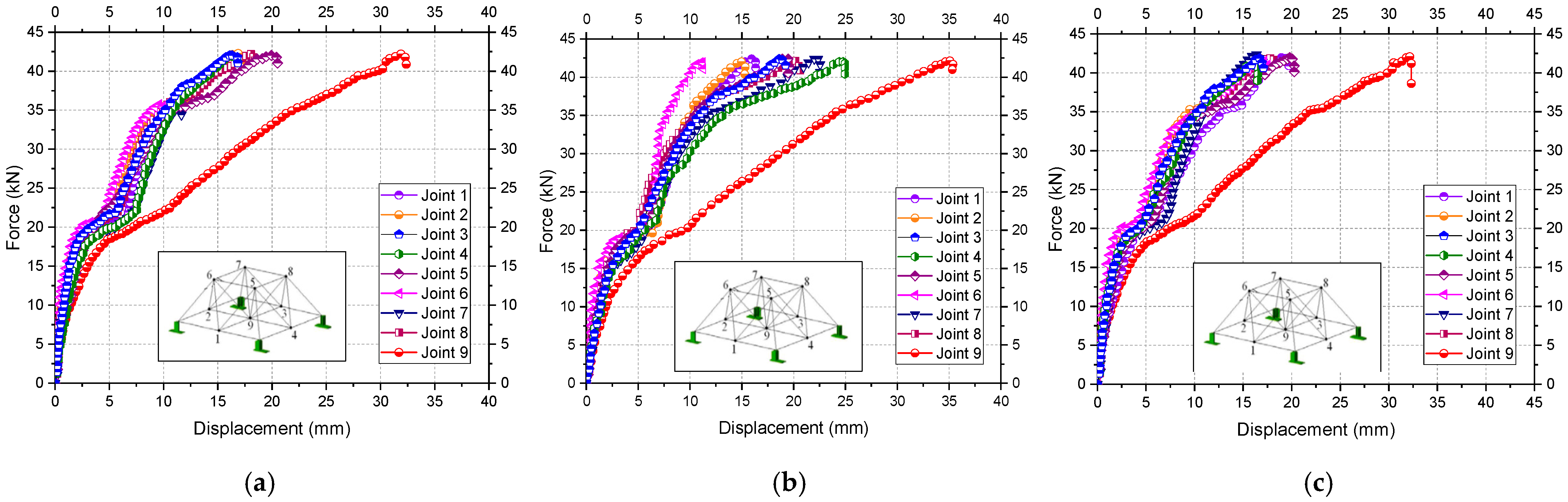
3.2. Results of the Testing on Reduced Space Trusses

The results of the experimental tests demonstrated a very great similarity in the failure mode initially predicted in the preliminary modeling in FE with ABAQUS used shell elements. The Typical Connection without spacer TCST had a global rupture characterized by the failure of the bars in the corner diagonals, the values of load vs. displacement are shown in Figure 13. Figure 14 shows the shapes of the structure after collapse.
The models with the space truss TCSS had local rupture in the top chords in the region where the bars were flattened; however, the diagonals did not fail, nor were there any more rotations in the connections. The failure load of the truss was higher than the Typical Connection with an average value of 34.25 kN. The Typical Connection had an approximate average force at collapse of 25.61 kN. There was an increase in load capacity of approximately 25% only with the use of the spacer (see Figure 15 and Figure 16).
The last series of tests was the that presented the best results, confirming the preliminary study with numerical simulation via ABAQUS with shell element. The use of the reinforcement plate in conjunction with the spacer significantly improved the results. In this series of experimental tests TCSSP, all bar failures were characterized by global buckling of the top chords. All connections remained intact throughout the test, the average recorded force in the collapse of the space trusses was around 45.18 kN. An increase in resistant capacity compared to the first TCST tests of 43%. Regarding connections with spacers without the reinforcement plate TCSS, there was an increase of approximately 24%, and no local collapse occurred. The values of load vs. displacements are shown in the graphs in Figure 17. The failure modes of the bars are shown in Figure 18.

3.3. Testing in Full-Scale Space Trusses

Next, the efficiency of the spacer with the reinforcement plate in the TCSSP used in the reduced truss was tested. A new series of experimental tests was carried out, this time, with full-scale trusses with a length of 8.64 m, a width of 5.76 m, and a height of 1.06 m. In this new experimental series, six tests were carried out. There are two tests per Typical Connection system. In the first case, it was decided not to use any spacer, to establish the reference collapse load. In the second model, the spacer was used at set with the reinforcement plate. In the third test, another spacer was adopted, made from recycled material, from the tire used in large vehicles, which has high compressive strength. This was also selected because it presents no issues with creep, as it is a viscoelastic material that has multiple steel filaments between the rubber layers. The use of a steel spacer proved to be satisfactory in correcting eccentricity.
However, the manufacture of the steel spacer requires specific equipment with plasma cutting, which has a high cost in acquiring the structural element, in addition to the significant increase in the self-weight of the spatial structure. Therefore, we sought to apply an easily accessible material with low self-weight and with good compressive strength, with a lower cost in acquiring the raw material. Therefore, the recycled tire from a large vehicle, used as a constituent material in the space truss, proved to be viable, in addition to the innovation in its use as a dissipation dynamic element, it also has mechanical characteristics suitable for use in static loading and contributes to mitigating environmental impacts.
Tires are waste that accumulates fast in large volumes, particularly in densely populated urban areas. The final destination of tires is a worldwide problem, and there is growing concern about policies to encourage the recycling, reduction, and reuse of tire waste. For this paper, a tire was used to manufacture the spacer to be applied in a space truss using a single-phase lathe (see Figure 19), with the total weight of the spacer being 0.0025 kN.
In order to compare the spacers with steel and with tire, the steel spacers were manufactured as reference with steel in USI SAC 350 with yield stress of 350 MPa. Steel spacers are expensive and consume more energy. The manufacture of spacers requires precision in dimensions. Therefore, it is necessary to resort to a manufacturing process that requires a specific machine to cut the thick steel plate. For the development of the spacer, a plasma cutting machine was used, which consists of the process of heat release by a plasma column, resulting from the heating of electric arcs together with a gas, in high rotational flow that makes the outline of the design of the spacer by cutting the steel sheet. Figure 20 shows the cut being made to obtain the steel spacer, with a total weight of 0.0083 kN, which is around 70% more weighty than recycled tire spacers.
For the purposes of this research, six static tests on trusses were constructed. The tests were done in the Laboratory of Structures of the Federal University of Cariri, UFCa in partnership with the University of Brasília-UnB. Details of the tests are summarized in Table 3 and also in Figure 21. The tested rectangle-on-rectangle trusses comprise 4 × 6 matrix pyramid units whose bases are 1.45 m × 1.45 m and 1.060 m in height. Diagonals form a 45° angle to the plane of the base, and the complete trusses are 5.76 m wide by 8.64 m in length. The materials used in the tests are as follows: (a) steel tubes: used as chords and diagonals with 38 mm external diameter and 1.50 mm thickness, made with MR-250, ABNT NBR 8800:2008 [30] similar to the ANSI/AISC 360:2016 [33], with the following engineering properties: a yielding stress of 250 MPa, a modulus of elasticity of 210,000 MPa, and Poisson’s ratio of 0.3; (b) spacers: made of steel or recycled tire with 20.00 mm thick; (c) steel bolt: 10 mm diameter per 80 mm length with yielding stress of 350 MPa; (d) steel nut and steel washer; and (e) reinforcing steel plate with an approximate thickness of 6.3 mm with 90.00 mm × 90.00 mm.
Figure 22 shows the dimensions of the space truss DLST tested in the laboratory.
The spacers used in Typical Connections were calculated using Equation (1), as shown in Equation (2), where H represents the height of the space truss, equivalent to 1060 mm. The eccentricity E1 was obtained from the distance between the center of the bolt hole and the angle of 45° of the bars, in the flattened area of the diagonal bar of the truss, in which the value found was 26.50 mm. Finally, l is equal to the length of the bar between the bolts with a dimension of l = 1450 mm and the thickness t of the bar is equal to t =1.50 mm. The value adopted for the spacer was d = 20.00 mm as follows:
d = 2 H E 1 l 2 4 E 1 8 t = 2 1060 26.50 1450 2 4 26.50 8 1.5 20.00   mm
Thus, prototypes were fixed on four rigid supports with loads applied on the nodes (P1, P2, P3, and P4). For the application of the load, steel cables (and steel clips) are used to tie the structure to four hydraulic jacks connected to a hydraulic actuator. The pump is driven by an electric engine (see Figure 23). The load is gradually applied and controlled by a load cell RS-5000 (with a 500 kN maximum capacity), associated with the reading panel HBM WE2108. On average, each test had 120 load steps with a value of 0.067 kN/min. Load is applied until the truss reaches collapse. The displacement measurements are performed at each loading step using Dial Test Indicators or deflectometers installed at the nodes where loads are applied.
The experimental results of the six tests are plotted in Figure 24 considering the nomenclature defined in Table 3 for the connection names with the values of load vs. displacement. The two tests carried out with the TCST1 and TCST2 prototypes presented final results with almost equal force at failure values, with a small difference in stiffness between the two tests. The process of applying the load steps had similarities between the two experimental tests. In the first test of the prototype TCST1, collapse occurred with an average applied force of 8.00 kN, applied at four points, which resulted in a total value of 32 kN, presenting an average displacement of 128.80 mm. Figure 24a shows the graph of the first test. Regarding the values obtained in the second test TCST2, the collapse mode of the structure occurred in a similar way to the first, with rupture of the Typical Connection of the diagonal support bar compressed in the end connection of the truss, and rotation of the Typical Connection with a value of force at rupture of 8.00 kN, applied at four points, which resulted in a value total also of 32.00 kN and with a displacement of 125.00 mm, as shown in Figure 24b.
Tests with steel spacers used in the two prototypes proved to be efficient in correcting eccentricity in Typical Connections with a change in rupture mode in relation to a Typical Connection without the spacer with buckling failure. In the first test with TCSSP1 eccentricity correction, the average rupture force of the truss was approximately 11.00 kN per point, resulting in the total value of 44 kN, and an average displacement of 105.00 mm. In the second test of the space truss, defined by the TCSSP2 prototype, the average rupture force did not change significantly, reaching an average value of the load point of 11.12 kN, resulting in the total value of 44.48 kN and an average displacement of 106 mm. In Figure 24c,d the results are presented in the graphs using force vs. displacement for the two prototypes.
The behavior of the prototypes using TCRTS recycled tire spacers, with nylon multifilament’s and steel wires in the composite matrix, guaranteed the spacer the mechanical resistance necessary to transfer the stress flows in the Typical Connection to the other elements of the truss, without suffering creep or large deformations. This is because the tire manufacturing process uses hydraulic presses that can weigh up to 400 tons for vulcanization, and goes through rigorous quality control processes. Therefore, the spacers, because they are not completely rigid, had greater accommodation in Typical Connections, and the results of this better adjustment with the use of the tire, gave a load vs. displacement plot with larger linear sections in relation to the other tests. Furthermore, a greater displacement of the spatial truss was also observed, being 10.85 kN per load point, resulting in the total value average of 43.61 kN. Thus, in TCRT 1, the value load was 43.84 and the displacement was 120.50 mm. The load was 43.38 in the second test, and the displacement was between 120.20 mm and 120.90. The two tests can be seen in Figure 24e and f, respectively.
The TCST collapsed by excessive distortion (see Figure 25) due to the bending moment. Eccentricities, in the Typical Connections, produce bending at nodes with reduced bending stiffness due to the end-flattened tubes. Another feature worth mentioning is that TCST collapses did not achieve the bearing capacity of the tubes but collapsed due to excessive distortion at the nodes, with enlargement of some holes in the plates caused by the bolt.
Reinforcing the Typical Connection, using the spacer plus the steel plate TCSSP and TCRTS, prevents local failure of the connection, and the buckling of the bar occurred, which was similar to the ideal trusses (see Figure 26). The tests showed that in the modified connections, there was a gain in resistance and a change in the way in which the structure began to fail. Global buckling in the top chord was evident in all modified connections. In the connections there were no rotations or plasticization of the stamped area. In the disconnected bars, no major distortions were found at the flattened ends, and no damage was found in the hole in the bar that connects the bolt, confirming that there was no rotation of the modified connection.

3.4. Considerations about Experimental Tests

In space trusses using spacers, collapses were characterized by buckling of the top chords. Spacers made of recycled tire or steel, reinforced with steel plates are more efficient with greater resistance of the space truss in collapse loads. However, the spacers from recycled tires are cheaper to manufacture and environmentally right. Conversely, for different TCST, the collapse of the structure always began with the reduction of the resistant capacity in the corner connections along the support diagonals. The contribution of reinforcement only with the steel plate in the Typical Connection does not result in an improvement in the mechanical behavior of the space truss, which is because the authors of this work also carried out two more experimental tests with a Typical Connection on a full scale, using only reinforcement plates in the Typical Connection. Nevertheless, the connection did not show an increase in resistance and failed locally in the Typical Connection with rotation and with premature failure without the occurrence of global buckling of the bars, showing that, without eccentricity correction with just the reinforcement plate, there is no gain of the resistance, as shown in Figure 27a.
Other studies [19,23] also reinforced the Typical Connection without correcting the eccentricity, using a type of washer in the shape of a cone, the cone surfaces of which were placed against the bar that was flattened at the end to form the Typical Connection, as shown in Figure 27b. The reinforcement introduced into the truss connection did not change the failure mode of the structure. The idea of the reinforcement was to increase the stiffness of the connection, preventing plastification of the stamped ends in the knot region. However, the behavior of the structure did not show any gain in terms of resistance. Thus, large vertical displacements were observed with slipping between bars and a concentration of deformations in the nodal region with local rupture.
In this context, it is evident from the many experimental tests that the best solution for the Typical Connection is the use of the spacer together with the reinforcement plate in the upper flanges. The spacer demonstrated in experimental tests that it actually prevents rotation of the connection, and, therefore, corrects the bending moments caused by the eccentricity arising from the stamping of the tubes. However, in addition to applying the spacer, it is necessary to use the overlapping plate on the top chords in order to avoid local plastification of the bar with the stamped area resulting from the bar flattening process. In preliminary tests with reduced truss and through the non-linear model year ABQUS, it was evident that, without the use of the overlapping plate, local instability of the bar occurs with premature failure of the truss and, when applying the spacer plus steel plate, local failure and the bending moment are resolved.
Experimental tests show that the reinforcement of typical TCSSP and TCRTS connections solves local rupture of the connections, and improves the resistant capacity of the spatial truss, but this solution requires the spacer to have compressive resistance to maintain the height necessary to correct the eccentricity and transfer the axial forces to the other elements of the truss. This is because the authors of this work also studied the application of other spacers in space trusses constructed from concrete with steel fiber. However, this did not produce satisfactory results, as shown in Figure 28, because the spacers did not withstand the efforts and cracked.
Consequently, knowing what stress the spacers are subjected to is essential for the proper sizing of this element. Furthermore, to finish other materials for new spacers, it is necessary to know what stress flow the Typical Connection will transfer to the spacer. Hence, a non-linear analysis was carried out on the spatial truss with a steel spacer, to find out what effort the spacers are subjected to in order to create a mechanistic criterion to assist in the sizing of this eccentricity correction device, with knowledge of the normal stress values in the spacers with the calibrated model.

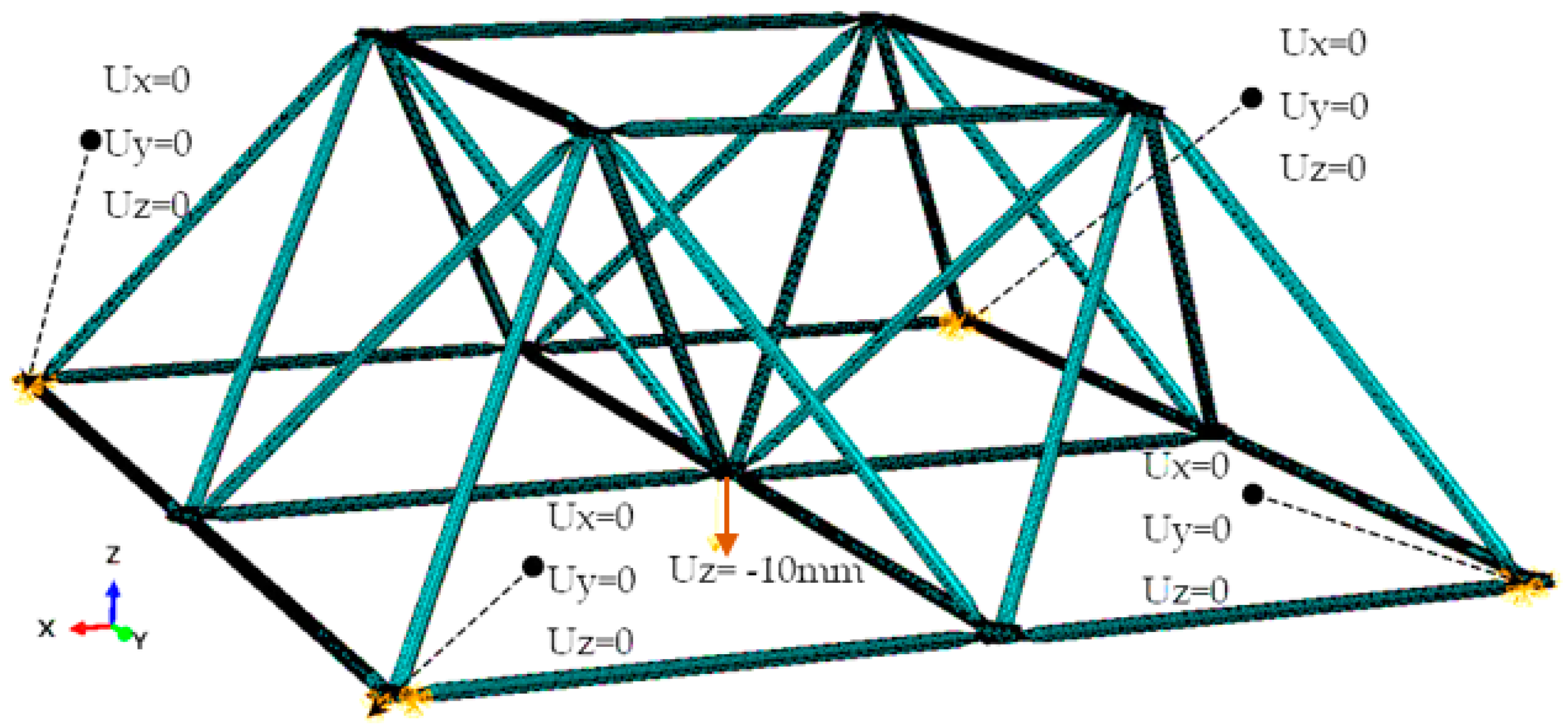
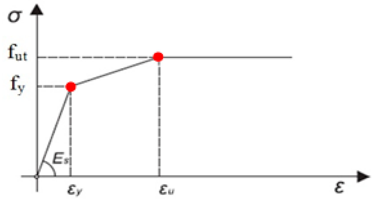
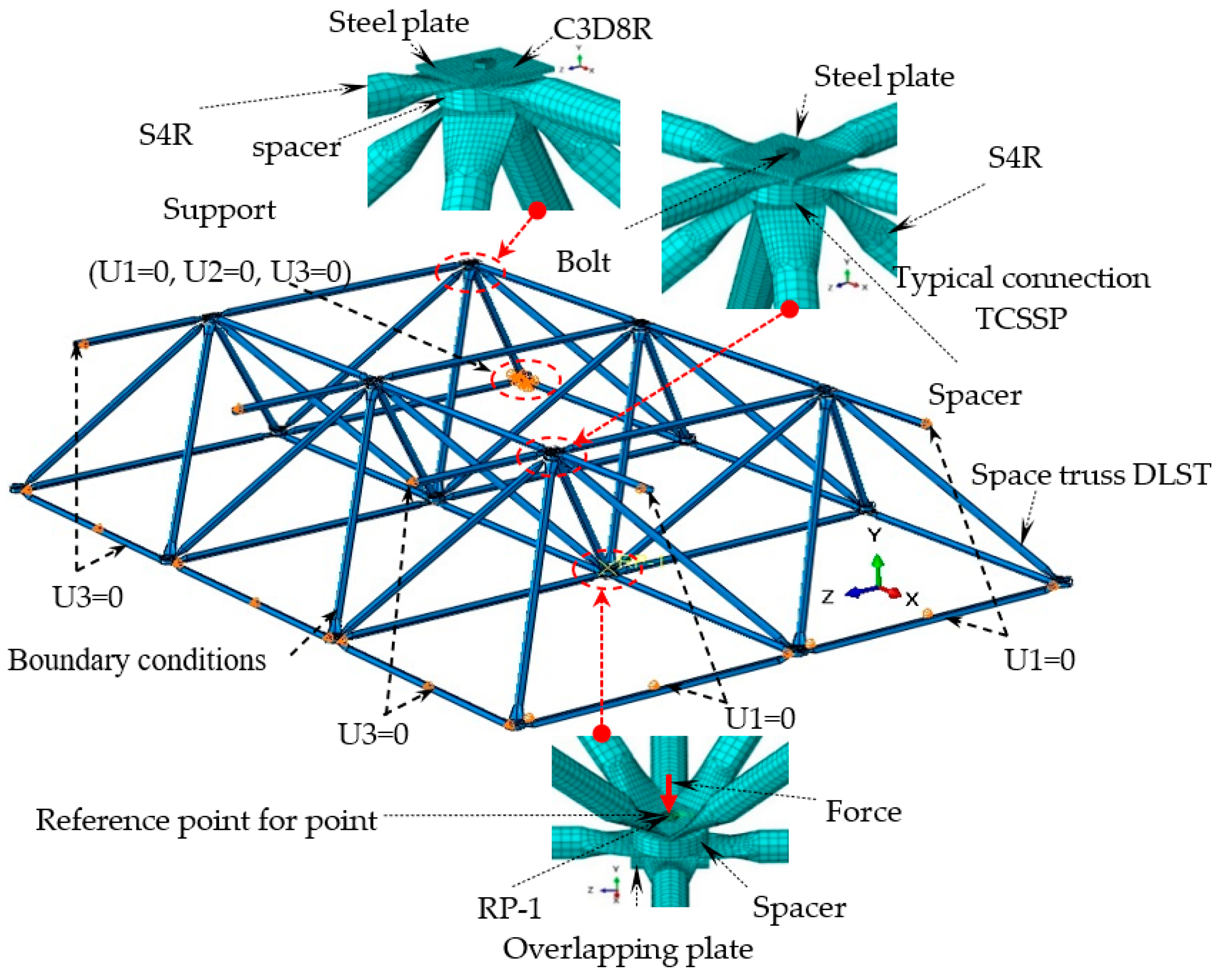
3.5. Numerical Simulation

The TCST and TCSSP were simulated in ABAQUS. To represent the physical nonlinearity of the steel, a bi-linear regime stress vs. strain diagram was used. The steel develops plastic deformations from the moment the proportionality tension is reached. In this curve, Young’s modulus is present at the initial behavior of the material and followed by strain hardening, then a plateau of plastic yield [37]. This constitutive relationship makes it possible to simulate the steel plasticization stages, which include: the linear regime, the proportionality tension, and the yield level. Therefore, the modeling of the truss elements was considered, under the elastic–plastic behavior. Figure 29 shows the presents the adopted curve [11,38,39].
To model the three-dimensional truss prototype, combinations of shell elements and solid elements were used, which are available in the ABAQUS library. Four-node elements (S4R) were used to model the truss bars, and eight-node elements (C3D8R) were used to model the spacers, overlapping plates, and bolts. The mesh on the truss members was employed with variable density in FE, refining the mesh towards the contact area of the truss connection between the members. The mesh used in spacers, plates, and screws has a uniform size of 5.00 mm. Figure 30 shows the finite element mesh.
The truss has planes of longitudinal and transverse symmetry—planes XY and YZ, respectively. Consequently, the truss members are sectioned by both planes. All nodes along the XY plane are prevented from moving in the Z direction (U3 = 0). Likewise, all nodes along the YZ plane are prevented from moving in the X direction (U1 = 0) shown in Figure 31. All nodes on the truss support contact surface were prevented from moving in the X, Y, and Z directions (U1 = U2 = U3 = 0). The numerical model considers a screw load generated by the tightening torque of 50 N.m applied to each screw carried out in the experimental tests. The “BOLT LOAD” option available in the ABAQUS load module was used to model this effect [37,40,41]. To reduce the complexity of the numerical model in relation to numerical convergence, the interaction between the truss members, such as the screw, spacer, and overlapping plate, were alternatively defined as rigid contacts using the TIE CONSTRAINT option available in ABAQUS. From a numerical point of view, to generate contact in this case, the surface-to-surface formulation was used. The load was applied incrementally at the reference point (RP-1) until the plasticization of the connections, where small load steps were applied using the modified ABAQUS RIKS algorithm. The graphs in Figure 29 show the results of load vs. displacement through the calibration of the experimental test. Figure 32 presents the comparison between the model failure modes in relation to the experimental tests.
From the calibrated model, six more spatial truss models were simulated in ABAQUS as a parametric study in FE. Thus, to evaluate the value of normal stress that the spacers are subjected to in the failure load of space trusses with a Typical Connection, different spacers were modeled following the formulation presented in Equation (1) to determine the height of the spacers. The meshes of the simulated spatial trusses are presented in Figure 33. The number of bars of each truss has a direct relationship with the height adopted for each model, and the same criterion was established for all trusses experimentally tested. The axial forces for each member of the DLSTs are shown in Figure 34.
The computational model FE demonstrated that the spacers are subjected to non-linear compression force in relation to the different spans studied. In practical design terms, it is not possible to define an equation for the compression design of the spacers, because there are many variables associated with the project that can interfere with the flow of normal stress that reaches the connection, such as: the length of the bars, tube thickness, spacing of three-dimensional meshes, variable design nodal force, and truss height, among others. Therefore, this work defined a stress range for each of the truss spans to support designers in defining preliminary projects when choosing the material for the spacer. Figure 35 details the normal stress flow for each of the trusses. Table 4 presents a summary of the results of the parametric study of the trusses.
In summary, the results show that TCST specimens present the largest local distortions and deformation. On average, the TCST collapse load was 32.00 kN, corresponding to 126.90 mm of average vertical displacement. For the TCSSP prototypes, the average displacement was 105.50 mm, with the average collapse load of 44.40 kN. Likewise, for the TCRTS prototypes, collapses took place at an average load of 43.61 kN and an average displacement of 120.70 mm. Therefore, in terms of average, TCST showed displacement 5.00% greater than TCRTS and 16.86% greater than TCSS. Another important observation is that, on spacers made of steel or recycled tire (TCSS or TCRTS) there was a resistance gain, at collapse, of approximately 27.92% and 26.62%, respectively, compared to the TCTS with bar buckling.

4. Conclusions

Steel tube connections with the superposition of flat ends screwed together with just one screw, known as a Typical Connection, have shown global collapse throughout the world. They are cheap and easier to assemble and are in the public domain. However, this structural system presents a risk of collapse, due to eccentricities in the connection that diverge from the ideal node system. Therefore, many collapses using these space trusses have been identified in the literature over the years. The experimental tests together with the complex FE models in ABAQUS demonstrate that trusses with a Typical Connection require reinforcement with the insertion of the spacer, together with an overlapping steel plate. In this research, the use of several spacers significantly increased the load capacity of Typical Connections characterized by global rupture due to buckling.
Conversely, the height and dimension of the spacers were also treated in this research with a study of the stress flow for practical assistance in project design through parametric study. A new type of spacer obtained from recycled tires was presented, which showed results compatible with a steel spacer. A broad experimental study on eccentricity in Typical Connections was presented, with nine tests on a smaller-scale structure, until arriving at the broader study of a space truss with full-scale dimensions.
In other research published by the authors of this work, the focus was on the evaluation of alternative spacers to steel to solve eccentricity in trusses with spans of to 10.00 m of length. However, in this paper, we sought to study the different spacers applied to trusses with larger spans. In this sense, a parametric numerical study in FE with ABAQUS was carried out with trusses with free spans between 10.00 m to 60.00 m and different heights, starting with a height of 1.01 m and reaching a height of 3.50 m. The results show that alternative spacers are limited to spans of 30.00 m. This is because spans greater than 30.00 m show a very large increase in stress concentration in the spacers. In practical design terms, a correlation between the free span and the stress in the spacers was presented, and is currently the most suitable spacer to support these stress flows for large free spans corresponds to the steel spacer. For spans smaller than 30.00 m, the ideal spacer would be made from recycled tires, as they have a lower cost and lower weight.
Several nonlinear models were presented in this research in order to simulate the behavior of the structure tested in the laboratory. The FE models present similar behavior to the experimental ones, with failure characteristics compatible with the experimental ones, where it was possible to carry out a parametric study to terminate the flow of normal stresses in the spacers for six types of typical trusses with different free spans. Studies show that:
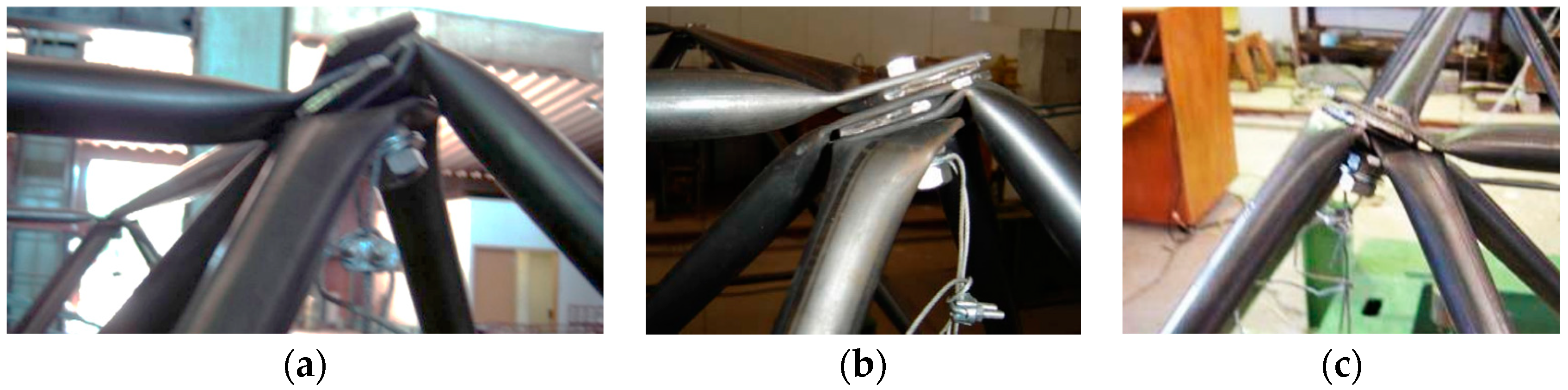
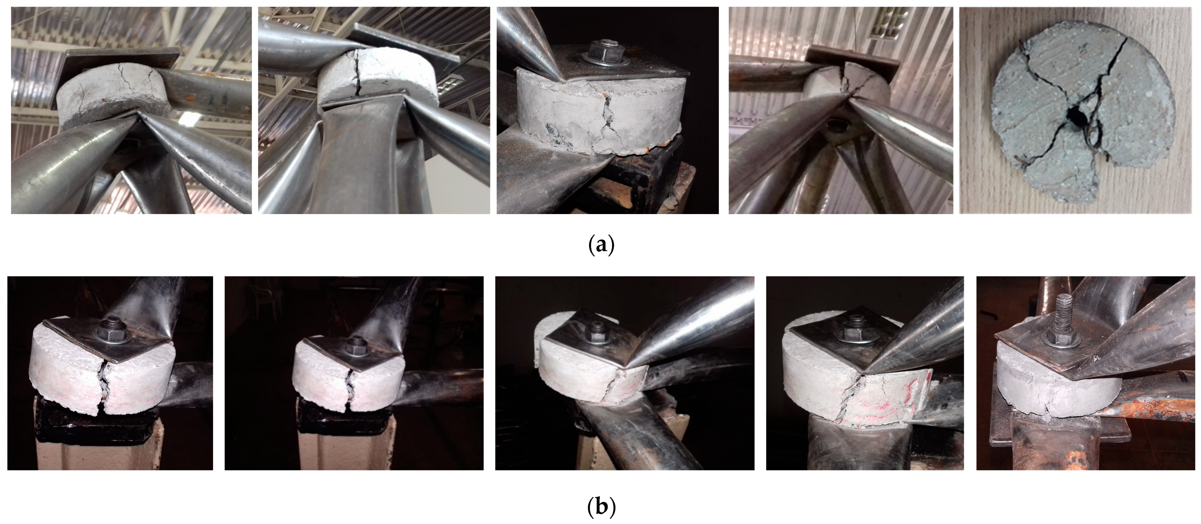
  • Typical Connections without structural reinforcement result in local collapse with distortions due to eccentricity with bending moment and premature rupture without taking advantage of the bar’s resistant capacity;
  • Typical Connections reinforced without the use of spacers with just the overlapping plate did not increase resistance and broke locally;
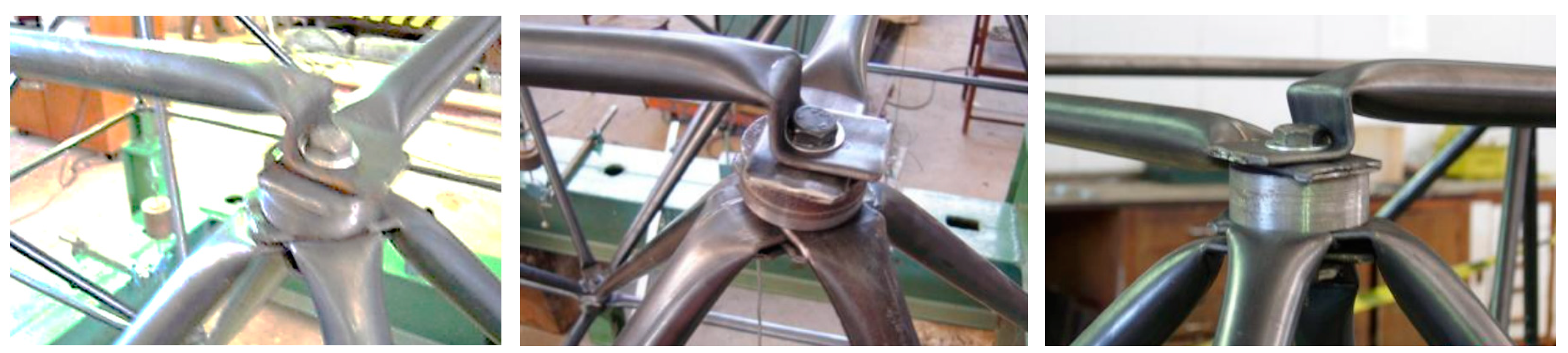
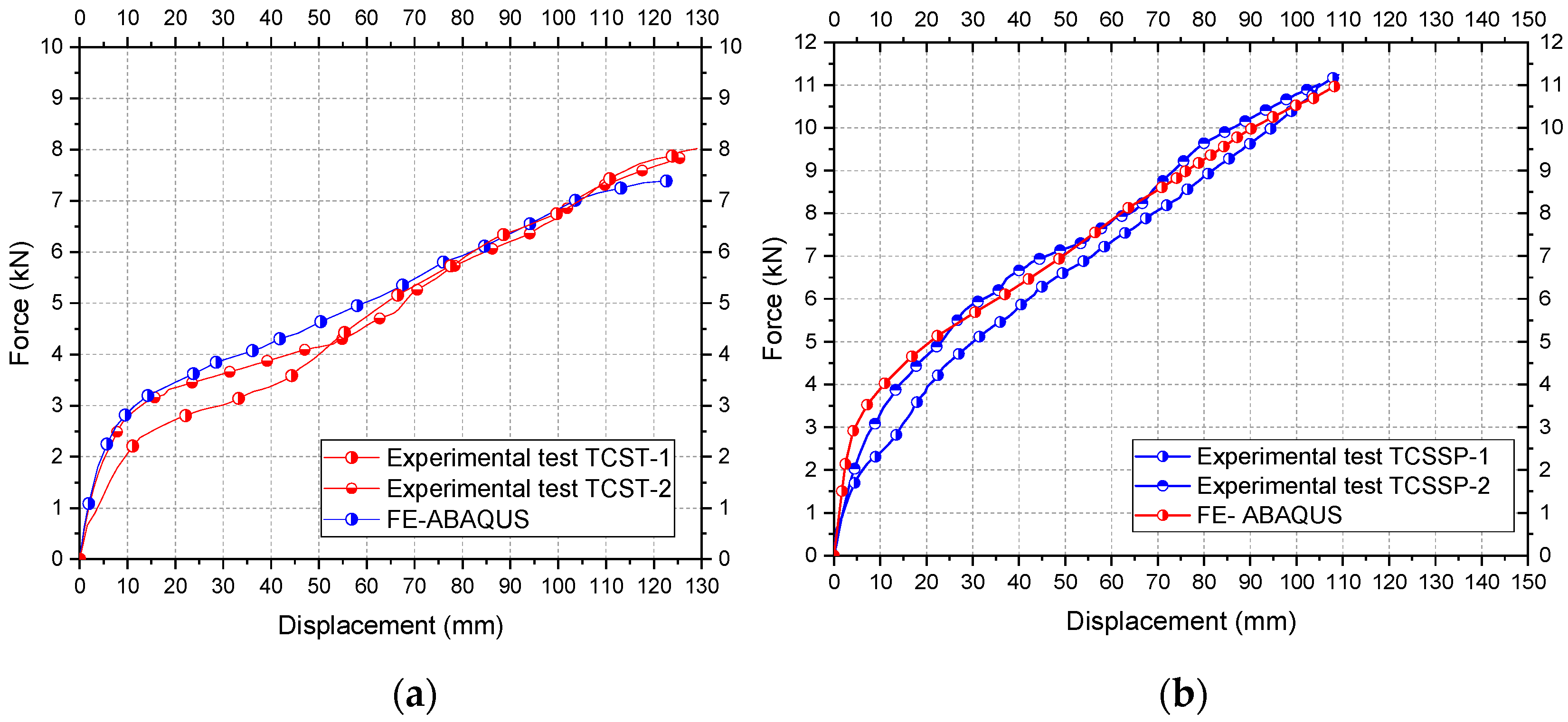
  • Tests on Typical Connections using spacers, on a small scale, but without the overlapping plate, failed locally in the stamped area of the top chord with an increase of only 24% in relation to Typical Connections without the spacer. Furthermore, there was no global failure with buckling of the bars;
  • In tests carried out with a Typical Connection, on a small scale, with a spacer together with the superimposed steel plate, the best results show a gain in resistance of around 43% compared to Typical Connections without reinforcement. In these prototypes, all failures were characterized by global buckling;
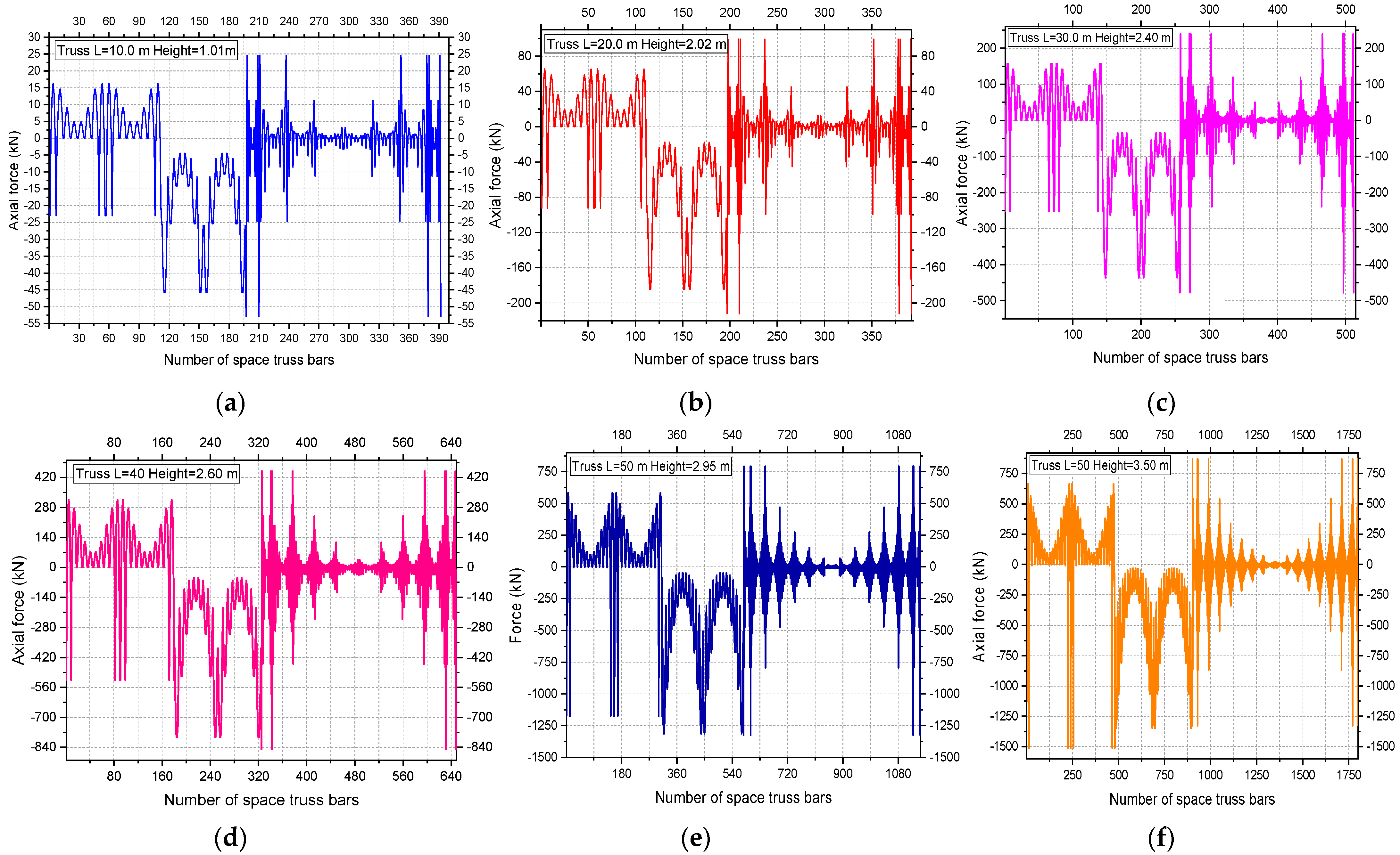
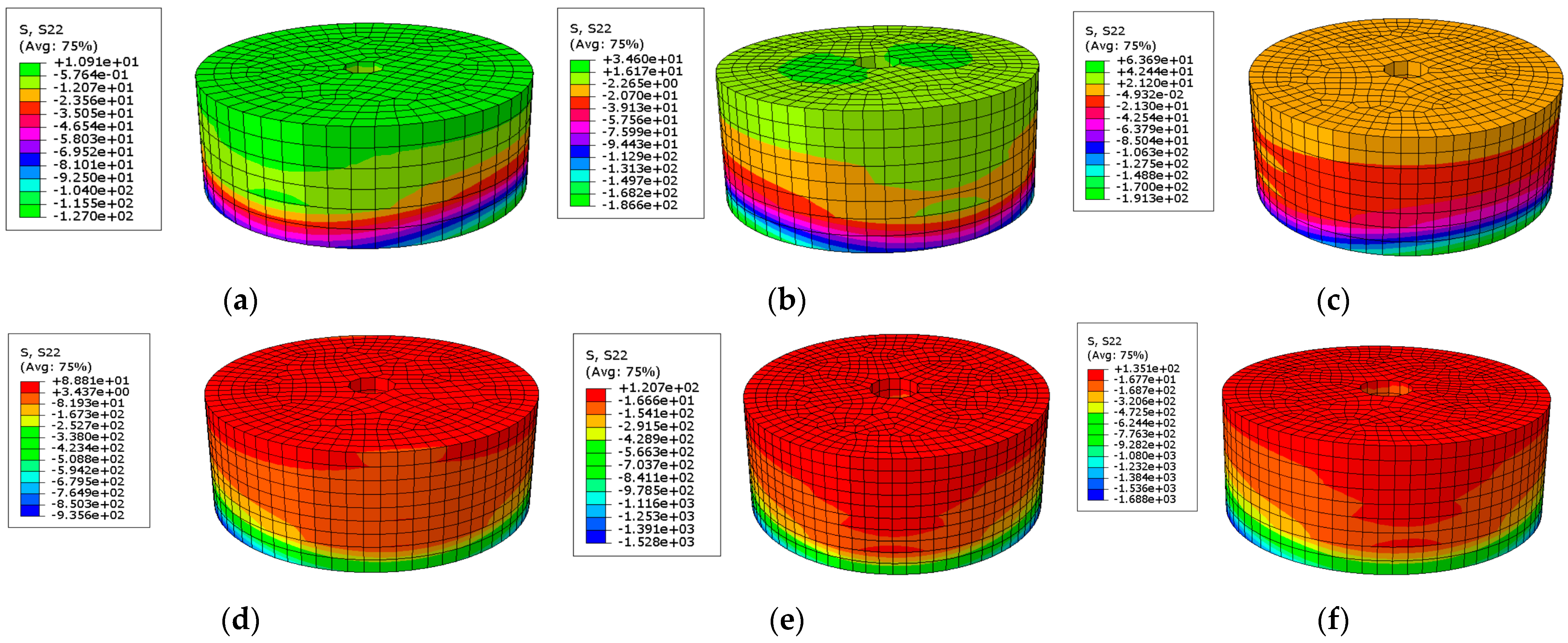
  • The parametric study with FE in ABAQUS demonstrated that the spacers of the full-scale truss are subjected to normal stress of around 8.96 MPa. Conversely, the parametric study showed that the normal stress flow in the spacers is not linear for the different truss spans;
  • To study the application of new spacers in design, the mechanical behavior of spacers for different types of space truss spans was presented with the aim of making it easy for designers to choose the eccentricity correction element with previously calculated normal stresses;
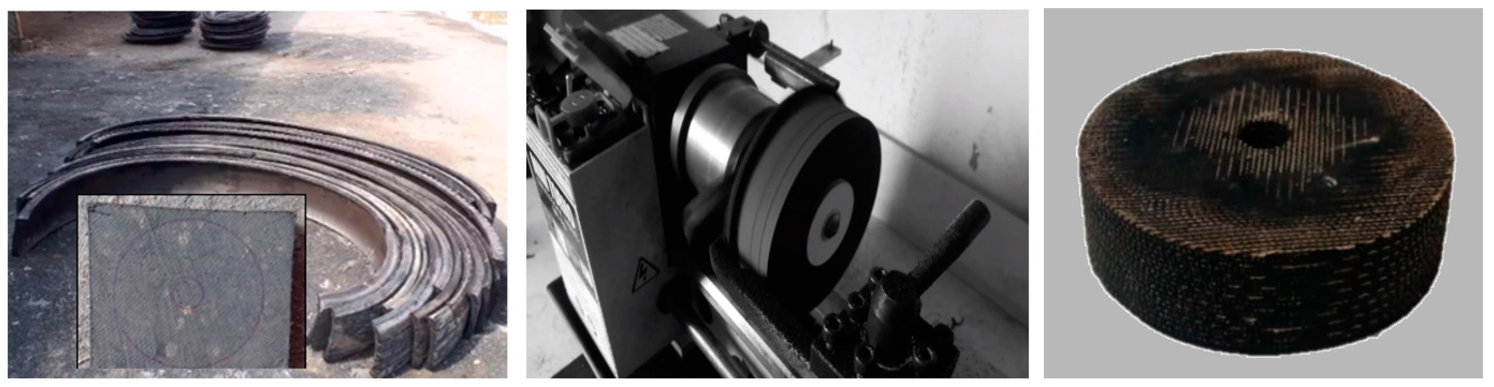
  • Through numerical simulation, it was demonstrated that the limitation on the use of spacers with recycled tires is for the use of trusses with spans over 30.00 m. This is because the compression stress (63.69 MPa) can confine the spacer and reduce the height of the element, compromising the accuracy in solving the eccentricity.

Author Contributions

W.V.: software, validation, formal analysis, investigation, resources, data curation, writing—original draft, writing—review and editing, visualization, supervision, project administration, funding acquisition. R.S.: software, validation, formal analysis, investigation, resources, data curation, writing—original draft, writing—review and editing, visualization, supervision, project administration, funding acquisition. L.M.B.: software, validation, formal analysis, investigation, resources, data curation, writing—original draft, writing—review and editing, visualization, supervision, project administration, funding acquisition. C.M.O.: software, validation, formal analysis, investigation, resources, data curation, writing—original draft, writing—review and editing, visualization, supervision, project administration, funding acquisition. C.A.S.F.: software, validation, formal analysis, investigation, resources, data curation, writing—original draft, writing—review and editing, visualization, supervision, project administration, funding acquisition. J.B.: software, validation, formal analysis, investigation, resources, data curation, writing—original draft, writing—review and editing, visualization, supervision, project administration, funding acquisition. All authors have read and agreed to the published version of the manuscript.

Funding

This study was funded by CAPES (the Brazilian Coordination for the Improvement of Higher Education Personnel) and CNPq (the National Council for Scientific and Technological Development) for the financial support for this research, and the authors thank the company Exact Engineering for financial support.

Data Availability Statement

Data is contained within the article.

Acknowledgments

The authors are thankful to the Structural Laboratory of the Federal University of Cariri and the Structural Laboratory of the University of Brasilia for all tests carried out in the course of this research, and to the Graduation Program in Structural Engineering of the University of Brasilia.

Conflicts of Interest

The authors declare no conflicts of interest.

References

  1. Makowski, Z.S.; Ramaswamy, G.S.; Eekhout, M.; Suresh, G.R. Book Review: Analysis, Design and Construction of Steel Space Frames. Int. J. Space Struct. 2002, 17, 243. [Google Scholar] [CrossRef]
  2. Chen, Z.; Li, J.; Zhang, S.; Yue, Q.; Huang, S. Progressive collapse demolition of double-layer space truss under different demolition load conditions. Eng. Struct. 2023, 294, 0141–0296. [Google Scholar] [CrossRef]
  3. Koushky, A.; Dehdashti, G.; Fiouz, A. Nonlinear Analysis of Double-Layer Grids with Compositive Nodes under Symmetric and Unsymmetrical Gravity Loads. Int. J. Space Struct. 2007, 22, 133–140. [Google Scholar] [CrossRef]
  4. Silva, W.V.; Silva, R.; Bezerra, L.M.; Freitas, C.A.S.; Bonilla, J. Experimental Analysis of Space Trusses Using Spacers of Concrete with Steel Fiber and Sisal Fiber. Materials 2020, 13, 2305. [Google Scholar] [CrossRef]
  5. Gioncu, V. Instability Problems in Space Structures. Int. J. Space Struct. 1985, 1, 169–183. [Google Scholar] [CrossRef]
  6. El-Shami, M.; Mahmoud, S.; Elabd, M. Effect of floor openings on the capacity of composite space trusses. J. King Saud Univ.—Eng. Sci. 2018, 30, 130–140. [Google Scholar] [CrossRef]
  7. El-Sheikh, A. New space truss system—From concept to implementation. Eng. Struct. 2000, 22, 1070–1085. [Google Scholar] [CrossRef]
  8. Freitas, C.A.S.; Silva, W.V.; Bezerra, L.M.; Neto, F.S.; Ribeiro, A.T. experimental analysis of space trusses with typical connections reinforced with steel and sisal-resin spacers. Int. J. Adv. Steel Constr. 2019, 15, 398–405. [Google Scholar] [CrossRef]
  9. Cleirton, A.S.; Freitas, L.M.; Bezerra, R.M.; Araújo, E.C.; Sousa, G.; Araújo, M.; Bezerra, É.A. New experimental results of the research on Reinforced node in space truss. Int. J. Adv. Steel Constr. 2017, 13, 30–44. [Google Scholar] [CrossRef]
  10. Rashidyan, S.; Sheidaii, M.R. Retrofitting collapse behavior of double layer space trusses against progressive collapse by force limiting devices. Adv. Steel Constr. 2022, 18, 804–817. [Google Scholar] [CrossRef]
  11. Silva, W.V.; Bezerra, L.M.; Freitas, C.S.; Bonilla, J.; Silva, R. Use of natural fiber and recyclable materials for spacers in typical space truss connections. J. Struct. Eng. 2021, 147, 04021112. [Google Scholar] [CrossRef]
  12. Liu, R.; Cheng, T.; Wen, P.; Wang, C.; Wang, G. Effect of the MHS on Earthquake Response of Space Truss Structures under Horizontal Earthquake Motion. Buildings 2023, 13, 523. [Google Scholar] [CrossRef]
  13. Souza, A.S.C.; Gonçalves, R.M.; De Nardin, S.; Calado, L. A strategy of numerical analysis of space truss connections with stamped bar ends. Int. J. Space Struct. 2008, 23, 143–152. [Google Scholar] [CrossRef]
  14. Doaei, Y.; Hosseini, S.E.A.; Momenzadeh, A.; Harirchian, E. Investigating the Effect of Screw Size on the Stress Level in MERO Joint for Space Frame Structures. Appl. Syst. Innov. 2021, 4, 84. [Google Scholar] [CrossRef]
  15. Subramanian, N. Space Structures: Principles and Practice; Multi-Science Publishing: Brentwood, UK, 2007; pp. 213–280. [Google Scholar]
  16. Bezerra, L.M.; de Freitas, C.A.S.; Matias, W.T.; Nagato, Y. Increasing load capacity of steel space trusses with end-flattened connections. J. Constr. Steel Res. 2009, 65, 2197–2206. [Google Scholar] [CrossRef]
  17. Mazon, A.A.; Sarmanho, A.; Nunes, G.; Roquete, L.; Neiva, L.H.; Souza, F. Numerical analysis of truss systems with stiffened flattened end-bars. Lat. Am. J. Solids Struct. 2018, 15, 1–24. [Google Scholar] [CrossRef]
  18. Malite, M.; Maiola, C.H.; Gonçalves, R.M.; Souza, A.C. experimental analysis of the structural performance of space trusses commonly used in Brazil. Int. J. Space Struct. 2001, 16, 253–260. [Google Scholar] [CrossRef]
  19. de Souza, A.S.C.; Gonçalves, R.M. Mechanism of Collapse of Space Trusses with Steel Hollow Circular Bars with Flattened Ends. Int. J. Space Struct. 2005, 20, 201–209. [Google Scholar] [CrossRef]
  20. Zhao, X.; Yan, S.; Chen, Y.; Xu, Z.; Lu, Y. Experimental study on progressive collapse-resistant behavior of planar trusses. Eng. Struct. 2017, 135, 104–116. [Google Scholar] [CrossRef]
  21. Xu, Z.; Yan, S. Progressive-Collapse Mechanism of Suspended-Dome Structures Subjected to Sudden Cable Rupture. Buildings 2023, 13, 1533. [Google Scholar] [CrossRef]
  22. Murtha-Smith, E.; Murtha-Smith, M.E.; Member, A. Alternate path analysis of space trusses for progressive collapse. J. Struct. Eng. 1998, 114, 1978–1999. [Google Scholar] [CrossRef]
  23. Malla, R.B.; Nalluri, B.B. Dynamic nonlinear member failure propagation in truss structures. Struct. Eng. Mech. 2000, 9, 111–126. [Google Scholar] [CrossRef]
  24. Shahzad, M.; Kamran, A.; Siddiqui, M.Z.; Farhan, M. Mechanical characterization and FE modelling of a hyperelastic material. Mater. Res. 2015, 18, 918–924. [Google Scholar] [CrossRef]
  25. Lee, C.H.; Kim, S.; Han, K.H.; Lee, K. Simplified nonlinear progressive collapse analysis of welded steel moment frames. J. Constr. Steel Res. 2009, 65, 1130–1137. [Google Scholar] [CrossRef]
  26. Yan, S.; Zhao, X.; Chen, Y.; Xu, Z.; Lu, Y. A new type of truss joint for prevention of progressive collapse. Eng. Struct. 2018, 167, 203–213. [Google Scholar] [CrossRef]
  27. Ma, Y.; Mi, J.; Yang, X.; Sun, Z.; Liu, C. Prediction model and sensitivity analysis of ultimate drift ratio for rectangular reinforced concrete columns failed in flexural-shear based on BP-Garson algorithm. Structures 2024, 60, 105808. [Google Scholar] [CrossRef]
  28. ABAQUS. Theory Manual, version 6.14.1; Dassault Systèmes Simulia: Providence, RI, USA, 2014.
  29. Liu, C.; Fang, D.; Zhao, L.; Zhou, J. Seismic fragility estimates of steel diagrid structure with performance-based tests for high-rise buildings. J. Build. Eng. 2022, 52, 104459. [Google Scholar] [CrossRef]
  30. Tsai, C.; Palazotto, A. A modified riks approach to composite shell snapping using a high-order shear deformation theory. Comput. Struct. 1990, 35, 221–226. [Google Scholar] [CrossRef]
  31. Fang, Y.; Sun, Z.-L.; Shang, L. An integrated algorithm for NRSFM with RIKs. In Proceedings of the 2014 Fifth International Conference on Intelligent Control and Information Processing (ICICIP), Dalian, China, 18–20 August 2014; pp. 482–484. [Google Scholar] [CrossRef]
  32. GB/228.1-2010; Metallic Materials-Tensile Testing-Part 1: Method of Test at Room Temperature. Standards Press of China: Beijing, China, 2010. (In Chinese)
  33. ASTM A36/36M; Standard Specification for Carbon Structural Steel: Annual Book of ASTM Standards. ASTM: West Conshohocken, PA, USA, 2008.
  34. ABNT NBR 8800; ABNT (Associação Brasileira de Normas Técnicas) NBR. Design of Steel and Composite Structures for Buildings. ABNT NBR: Rio de Janeiro, Brazil, 2008.
  35. ASTM E1875-13; Standard Test Method for Dynamic Young’s Modulus, Shear Modulus, and Poisson’s Ratio by Sonic Resonance. ASTM: West Conshohocken, PA, USA, 2013. [CrossRef]
  36. ANSI/AISC 360; Specification for Structural Steel Buildings. AISC: Chicago, IL, USA, 2016.
  37. Wu, S.; Fu, Y.; Wu, G.; Xia, M. Numerical simulation study of influence of friction coefficient of die based on Abaqus on V-shaped clamp stamping parameters. Adv. Mech. Eng. 2021, 13, 1–14. [Google Scholar] [CrossRef]
  38. Vital, W.; Silva, R.; de Morais, M.V.; Sobrinho, B.E.; Pereira, R.; Evangelista, F. Application of bridge information modelling using laser scanning for static and dynamic analysis with concrete damage plasticity. Alex. Eng. J. 2023, 79, 608–628. [Google Scholar] [CrossRef]
  39. Mäntylä, A.; Hintikka, J.; Frondelius, T.; Vaara, J.; Lehtovaara, A.; Juoksukangas, J. Prediction of contact condition and surface damage by simulating variable friction coefficient and wear. Tribol. Int. 2019, 143, 106054. [Google Scholar] [CrossRef]
  40. Li, L.; Mu, D.; Liu, Y.; Li, Z.; Yin, Q.; Chang, H. Anchor Behavior of One-Side Bolt with Flip-Top Collapsible Washer. Buildings 2023, 13, 1571. [Google Scholar] [CrossRef]
  41. Wang, W.; Li, M.; Chen, Y.; Jian, X. Cyclic behavior of endplate connections to tubular columns with novel slip-critical blind bolts. Eng. Struct. 2017, 148, 949–962. [Google Scholar] [CrossRef]
Figure 1. Alternative connections classified as Typical Connections used in space trusses. (a) Details of Typical Connection using one bolt; (b) application system 1; (c) Typical Connection with weld using sixteen bolts; (d) application system 2; (e) Typical Connection with weld and plate gusset in bars; (f) application system 3.
Buildings 14 00608 g001
Figure 2. Typical Connection. (a) Connection with eccentricity and (b) eccentricity correction.
Buildings 14 00608 g002
Figure 3. Development of eccentricity correction for Typical Connection.
Buildings 14 00608 g003
Figure 4. Preliminary numerical simulation. (a) Ideal Connection; (b) Typical Connection with flattened bar; (c) Typical Connection with flattened bar using spacers; and (d) Typical Connection with flattened bar using spacers and reinforcement with plate overlapped.
Buildings 14 00608 g004
Figure 5. 3D model of the space truss DLST used in the preliminary study of the connection.
Buildings 14 00608 g005
Figure 6. Steel tensile test with calibration of the numerical model in ABAQUS.
Buildings 14 00608 g006
Figure 7. Preparation of the bar in REVIT for import into ABAQUS. (a) Cutting the lattice bar in the stamping zone; (b) modeling the bar in REVIT based on the bar cuts in the stamped area, and (c) 3D connection modeled in ABAQUS using TIE contact between the bars.
Buildings 14 00608 g007
Figure 8. (ac) Failure of the connection IC at 50%, 70 and 100%; (df) failure of the connection TC with percentage at 50%, 70%, and 100%; (gi) local failure of Typical Connection with spacer TCS without overlapping plate, with Von Mises stress at 50%, 70%, and 100%; (jl) Typical Connection with spacer and overlapping plate TCSP with stress values of 50%, 70%, and 100%.
Buildings 14 00608 g008aBuildings 14 00608 g008b
Figure 9. Global evaluation of space trusses with failure forces NFORCS. (a) Space truss with IC; (b) space truss with TC connection; and (c) space truss with TCS connection.
Buildings 14 00608 g009aBuildings 14 00608 g009b
Figure 10. Relationship of the bending moment in the three trusses.
Buildings 14 00608 g010
Figure 11. Prototype in experimental test position and connection name.
Buildings 14 00608 g011
Figure 12. Prototype in experimental test. (a) Space truss test arrangement; (b) prototype with connection numbering where the LVDTs were installed; (c) space truss dimension with Typical Connection; (d) space truss dimension with Typical Connection used spacer; (e) dimensions of the chords; (f) dimension the of reinforcing steel plate; (g) dimension steel spacer in steel USI SAC 350 with 350 MPa; (h,i) dimension of diagonal and bar angle; (j) dimension of bolt.
Buildings 14 00608 g012aBuildings 14 00608 g012b
Figure 13. Values of the relationship of load versus displacement in TCST models. (a) Results of the first experimental test; (b) Results of the second experimental test; (c) Results of the third experimental test.
Buildings 14 00608 g013
Figure 14. Failure modes of the prototype TCST. (a) Typical bond distortion in the first test in TCST; (b) Typical bond distortion in the second test in TCST; (c) Typical bond distortion in the third test in TCST.
Buildings 14 00608 g014
Figure 15. Values of the relationship of load versus displacement in TCSS models. (a) First test with typical connection TCSS; (b) Second test with typical connection TCSS; (c) Third test with typical connection; test TCSS.
Buildings 14 00608 g015
Figure 16. Failure modes of the prototype TCSS.
Buildings 14 00608 g016
Figure 17. Values of the relationship of load versus displacement in TCSSP models. (a) First test with typical connection TCSSP; (b) Second test with typical connection TCSSP; (c) Third test with typical connection; test TCSSP.
Buildings 14 00608 g017
Figure 18. Failure modes of the prototype TCSSP. (a) First test with typical connection; (b) Second test with typical connection; (c) Typical connection detail after test.
Buildings 14 00608 g018
Figure 19. Detail of the manufacture of recycled tire spacer.
Buildings 14 00608 g019
Figure 20. Detail of the manufacture of steel spacer. (a) Start of cutting; (b) Making the center spacer hole; (c) Spacer made of steel.
Buildings 14 00608 g020
Figure 21. Typical Connection in space truss. (a,d) Typical Connection TCST; (b,e) Typical Connection with Steel Spacer with reinforcing steel plate, TCSSP; (c,f) Typical Connection using recycled tire spacer with reinforcing steel plate, TCRTS.
Buildings 14 00608 g021aBuildings 14 00608 g021b
Figure 22. The dimensions of the prototype tested in the laboratory.
Buildings 14 00608 g022
Figure 23. Instruments for acquiring data from experimental tests.
Buildings 14 00608 g023
Figure 24. Results of the experimental tests with full scale space trusses. (a,b) Connection TCST; (c,d) connection TCSSP; (e,f) connection TCRTS.
Buildings 14 00608 g024aBuildings 14 00608 g024b
Figure 25. Experimental tests on space trusses with Typical Connection without spacer in full scale. (a) Results of the collapse of the first experimental test; (b) results of the collapse of the second experimental test; (c) distortions in the Typical Connection bars after the experimental test.
Buildings 14 00608 g025aBuildings 14 00608 g025b
Figure 26. Shape of the structure after the global collapse. (a,b) The result of truss collapse of the TCSSP1 and TCSSP2; (c,d) the result of truss collapse of the TCRTS1 and TCRTS2; (e) spacer on space truss supports; (f) maximum displacement of the truss in the test and demonstration of the spacer in the connections after the test.
Buildings 14 00608 g026aBuildings 14 00608 g026b
Figure 27. (a) Failure to resolve the connection rotation with just the steel plate; (b) failure to resolve the connection without using the spacer.
Buildings 14 00608 g027
Figure 28. Spacers that did not withstand the stress and failed during the experimental test. (a) Failure of spacers in the upper connections; (b) Failure of spacers in support connections.
Buildings 14 00608 g028
Figure 29. Stress–strain relationship for steel material.
Buildings 14 00608 g029
Figure 30. Space truss modeled in ABAQUS by symmetry.
Buildings 14 00608 g030
Figure 31. Space truss modeled in ABAQUS by symmetry. (a) TCST comparison with numerical FE and (b) TCSSP comparison with numerical FE.
Buildings 14 00608 g031
Figure 32. Space truss modeled in ABAQUS with failure. (a) TCST comparison of failure modes with numerical FE and experimental test and (b) TCSSP failure modes with numerical FE and with experimental test of the space truss DLST.
Buildings 14 00608 g032
Figure 33. Space truss modeled in ABAQUS by symmetry. (a) Space truss with span of 10.0 m; (b) truss with span of 20.0 m; (c) truss with span of 30.0 m; (d) truss with span of 40.0 m; (e) truss with span of 50.0 m; and (f) space truss with span of 60.0 m.
Buildings 14 00608 g033
Figure 34. Results of the axial forces in the ABAQUS for the different space trusses. (a) Truss with a span of 10.0 m and a height of 1.01 m; (b) truss with a span of 20.0 m and a height of 2.02 m; (c) truss with a span of 30.0 m and a height of 2.40 m; (d) truss with a span of 40.0 m and a height of 2.60 m; (e) truss with a span of 50.0 m and a height of 2.95 m; and (f) space truss with a span of 60.0 m and a height of 3.50 m.
Buildings 14 00608 g034
Figure 35. Normal stress in spacer of the connections of the space trusses. (a) Spacer for a 10 m span; (b) spacer for a 20 m span; (c) spacer for a 30 m span; (d) spacer for a 40 m span; (e) spacer for a 50 m span; (f) spacer for a 60 m span.
Buildings 14 00608 g035
Table 1. Properties of steel.
Source of Test Piecesfy (MPa)fu (MPa)Elongation (%)Associated Figure
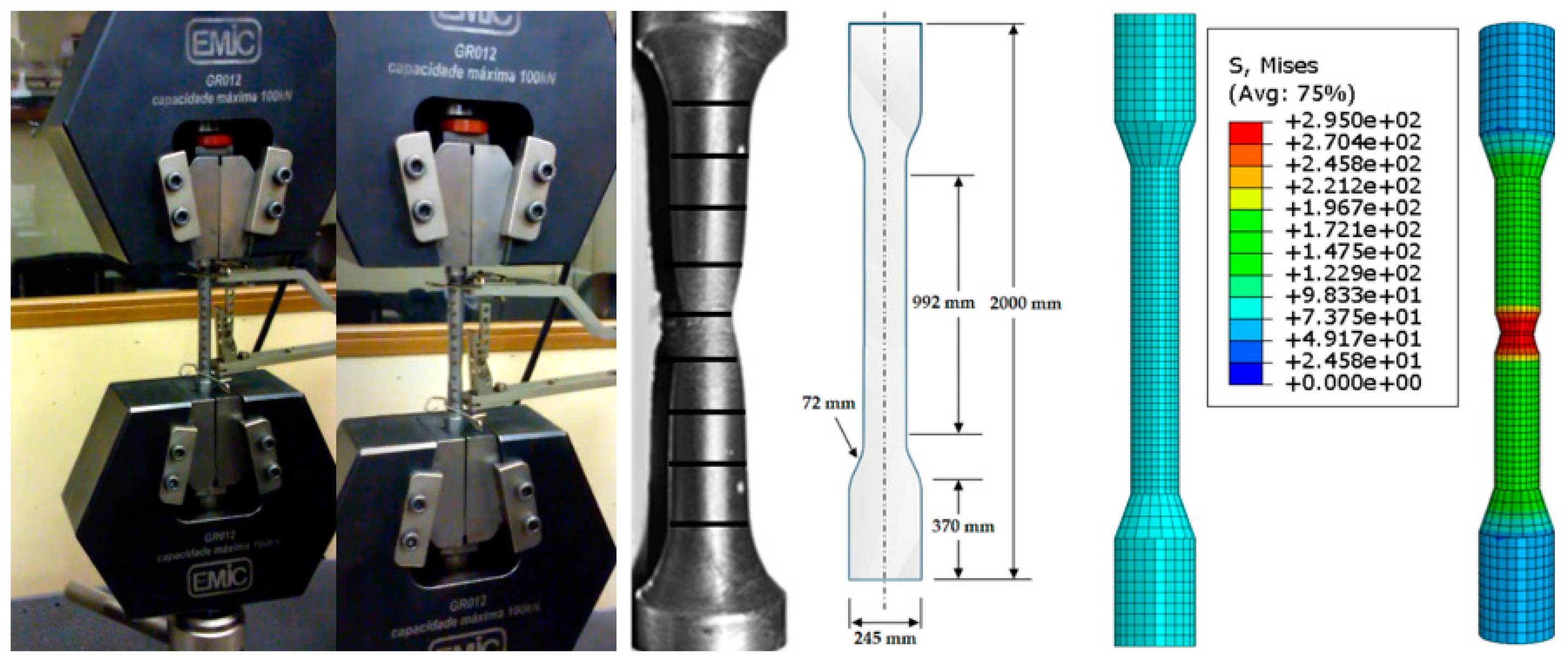
Circular machined section GB/T 228.1-2010, ASTM A36/36M [32,33]285.00295.0023.34Figure 5
Table 2. Performed tests with double-layer grid space truss on a reduced scale.
PrototypesConnectionType of Prototype TestedAssociated
NameStatic Load TestFigure
PROT 1TCST 01Typical Connection Space TrussFigure 11
PROT 2TCST 02Typical Connection Space Truss
PROT 3TCST 01Typical Connection Space Truss
PROT 4TCSS 01Typical Connection with Steel Spacer without reinforcing steel plate
PROT 5TCSS 02Typical Connection with Steel Spacer without reinforcing steel plate
PROT 6TCSS 03Typical Connection with Steel Spacer without reinforcing steel plate
PROT 7TCSSP 01Typical Connection with Steel Spacer with reinforcing steel plate
PROT 8TCSSP 01Typical Connection with Steel Spacer with reinforcing steel plate
PROT 9TCSSP 02Typical Connection with Steel Spacer with reinforcing steel plate
Table 3. Performed tests with double-layer grid space truss.
PrototypesConnectionType of Prototype TestedAssociated
NameStatic Load TestFigure
PROT 1TCST 01Typical Connection Space TrussFigure 21
PROT 2TCST 02Typical Connection Space Truss
PROT 3TCSSP 01Typical Connection with Steel Spacer with reinforcing steel plate
PROT 4TCSSP 02Typical Connection with Steel Spacer with reinforcing steel plate
PROT 5TCRTS 01Typical Connection using Recycled Tire Spacer with reinforcing steel plate
PROT 6TCRTS 02Typical Connection using Recycled Tire Spacer with reinforcing steel plate
Table 4. Parametric numerical simulation results.
Span TrussHeights (mm)Bar NumberAxial Force (kN)Diameter (mm)Area (mm2)Spacer (mm)Normal Stress (MPa)
10.001010.00392.00554.8180.005024.0030.0010.91
20.002020.00392.00220.0090.006358.5035.0034.60
30.002400.00512.00499.96100.007850.0040.0063.69
40.002600.00648.00843.56110.009498.5045.0088.81
50.002950.001152.001364.39120.0011,304.0048.00120.70
60.003500.001800.001792.90130.0013,266.5055.00135.14
Disclaimer/Publisher’s Note: The statements, opinions and data contained in all publications are solely those of the individual author(s) and contributor(s) and not of MDPI and/or the editor(s). MDPI and/or the editor(s) disclaim responsibility for any injury to people or property resulting from any ideas, methods, instructions or products referred to in the content.

