Article

Full Size Two-Layer Steel Frame–Exterior Wall Panel Shaking-Table Test

1
The Key Laboratory of Urban Security and Disaster Engineering, Ministry of Education, Beijing University of Technology, Beijing 100124, China
2
Architectural Engineering Institute, Tianjin Renai College, Tianjin 301636, China
3
Beijing Shoushi Industrial Design Limited Company, Beijing 100043, China
*
Author to whom correspondence should be addressed.
Buildings 2024, 14(3), 634; https://doi.org/10.3390/buildings14030634
Submission received: 15 January 2024 / Revised: 3 February 2024 / Accepted: 12 February 2024 / Published: 28 February 2024
(This article belongs to the Topic Advances on Structural Engineering, 2nd Volume)

Abstract

:
A cantilever block wall-panel attachment strip (CBW) flexible connection node was designed to connect precast concrete (PC) exterior wall panels to steel frames. To investigate the performance of the CBW flexible connection node and PC exterior wall panels during earthquakes, a partial two-storey steel frame was extracted from an actual engineering structure, and a full-scale steel frame–exterior wall panel shaking-table model was designed. Two sets of shaking-table tests were conducted under seismic intensity 7, 8, and 9 (Chinese Seismic Intensity Scale) earthquakes. The acceleration and displacement responses of the composite wall panel, open window panel, and integral wall panel along the in-plane and out-of-plane motions were analysed. The acceleration amplification factors of the PC exterior wall panels ranged from 0.753 to 1.400 (in-plane) and from 0.998 to 2.199 (out-of-plane). The CBW flexible connection node had a deformation capacity that could coordinate the deformation of the exterior wall panel and prevent severe damage. The surfaces of the PC exterior wall panels remained intact during a very strong seismic intensity 9 earthquake.

1. Introduction

Exterior wall panels are the most frequently used enclosure components in prefabricated buildings. Two types of connections exist between the exterior wall panels and main structure: line-supported and point-supported connection nodes [1]. Line-supported connection nodes have complicated mechanical characteristics. If adequate clearances cannot be ensured on the other sides, the exterior wall panels may crack prematurely during seismic-activity-induced main structure deformation. Conversely, point-supported connection nodes are convenient to construct and exhibit simple mechanical characteristics. Despite being considered as non-load-bearing components in structural design, exterior wall panels significantly affect the seismic performance of the main structure [2,3,4,5,6,7,8]. If a dependable connection is not established between the main structure and the exterior wall panels, they could easily detach under earthquake activity, thus leading to additional casualties and damages due to falling wall panels.
Jingfeng [9,10], De Matteis [11], Cao [12], Gokmen [13], and Bo Wang [14] have conducted quasi-static tests on single-storey, steel-frame structures with or without exterior wall panels. The results have indicated that the wall panels utilising flexible connection nodes improved the lateral load capacity and stiffness of the empty frames. Vaghei [15] and Liu [16] studied the performance of flexible connection nodes under cyclic loads. The results revealed that flexible connection nodes can withstand multidirectional earthquakes and reduce the adverse impacts of earthquakes on the surrounding structural systems. Du [17] and Cui [18] proposed a steel-frame autoclaved aerated concrete (AAC) exterior wall panel connection node. The mechanical characteristics of the exterior wall panel and connection nodes were studied through shaking-table tests. The results showed that the structural components, including the joint connections between the steel frame and the walls, behaved well. The seismic performance of two full-scale, three-storey steel frame–exterior wall panel models was investigated through shaking-table tests by Fang [19], who found that the exterior wall panel did not exhibit significant cracking or damage under a seismic intensity of 9, and the connection node provided sufficient flexibility deformation. The PC exterior wall panel had high in-plane stiffness but low out-of-plane stiffness. Under seismic loading, the precast concrete exterior wall panels with thin thicknesses experienced significant out-of-plane inertial forces due to their high self-weights. However, the aforementioned studies focused on the seismic performance of the exterior wall panel in-plane, and less attention was paid to the out-of-plane performance of the exterior wall panels.
A cantilever block wall-panel attachment strip (CBW) flexible connection node was proposed for the PC exterior wall panels in this study. A local two-storey steel frame was selected from an assembled building structure, and three different full-scale types of exterior wall panels (a composite wall panel (numbered SP-1), an open window panel (numbered SP-2), and an integral wall panel (numbered SP-3)) were designed to connect to the steel frame. Two sets of shaking-table tests were conducted on a full-scale, two-storey steel frame–exterior wall panel structure model by inputting 12 natural seismic and floor seismic responses (obtained by a finite element analysis of the actual engineering structure). The flow diagram for the research is shown in Figure 1. The acceleration amplification factor (the amplification of the acceleration of the exterior wall panels relative to the steel beam) and deformation of the CBW flexible connection nodes on three exterior wall panel types were analysed for the in-plane and out-of-plane loadings under the effects of rare earthquakes with seismic intensities of 7, 8, and 9. The results of this study will have a significant impact on the development of prefabricated buildings.

2. Materials and Methods

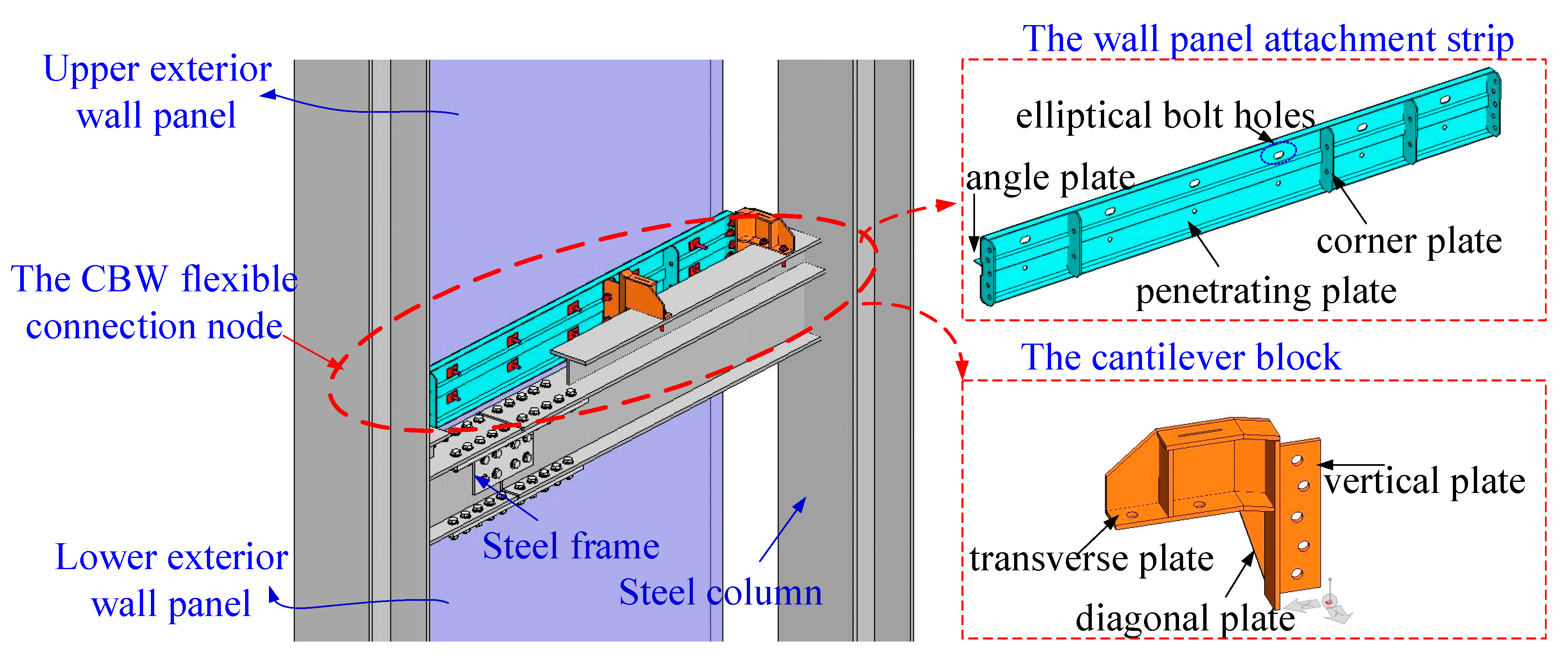
2.1. CBW Flexible Connection Node
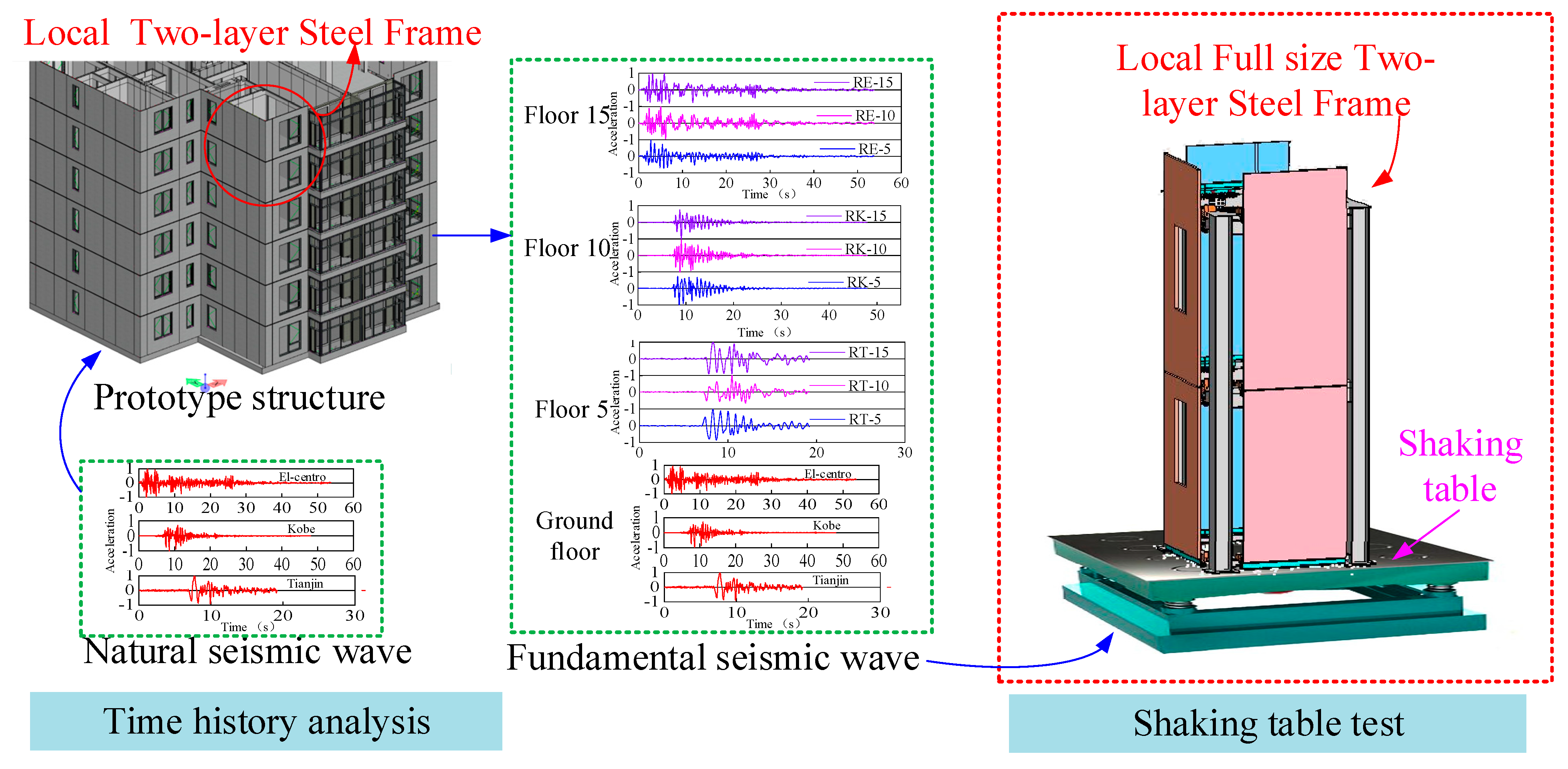
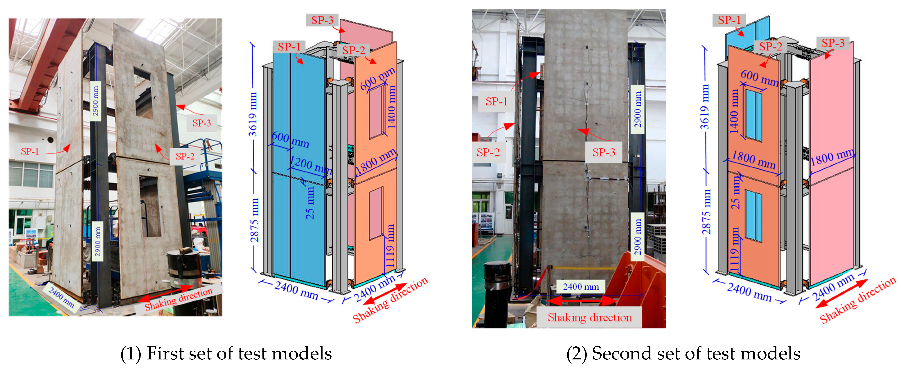
A CWB attachment strip flexible connection node was used to connect the exterior panel to the main structure of an assembled steel structure, as shown in Figure 2. The CBW flexible connection node was composed of a wall-panel attachment strip and a cantilever block, both of which were steel members with fixed types and sizes that could be used in combination (Figure 3). The wall-panel attachment strip was connected to the exterior wall panel, the cantilever block was connected to the steel-frame beam, and the wall-panel attachment strip was bolted to the cantilever block to connect the exterior wall panel to the main structure.
The wall-panel attachment strip comprised a penetrating plate, angle plate, and corner plate. The penetrating plate contained two rows of bolt holes that were used to connect the upper and lower exterior wall panels. The first row of bolt holes consisted of elliptical bolt holes connected to the bottom of the upper exterior wall panel (used as the lower connector), thereby allowing the exterior wall panel to slide, whereas the second row of bolt holes were common bolt holes attached to the top of the lower exterior panel (used as an upper connector). The angle plate supported the exterior wall panel, whereas the corner plate and cantilever block were connected using bolts.
The cantilever block was composed of completely stamped steel consisting of transverse, diagonal, and vertical plates. The transverse and vertical plates primarily served as connectors, whereas the diagonal plate served as reinforcement. The cantilever blocks were spaced along the steel-frame beams and exhibited flexibility whilst experiencing deformation. Compared with the rigid connection nodes, the CBW flexible connection nodes possessed deformation tolerance and were capable of coordinating the deformation of the exterior wall panels. In contrast to other flexible connection nodes, they were easier to install, had superior deformation capacity, and effectively minimised earthquake damage to the exterior wall panels.
The self-weight, seismic, and wind loads of the exterior wall panels were transmitted to the main structure through a wall-panel attachment strip and cantilever block. According to the Chinese technical standard for assembled buildings with a steel structure [20], a CBW flexible connection node under the ultimate limit state must experience no damage, which requires that the safety margin of the bearing capacity at the connection satisfy the requirements of the exterior wall panel. The size, quantity, and spacing of the connecting bolts and the spacing of the cantilever block were determined by calculations, all of which satisfied the requirements of the technical standard [20]. To avoid the assembly site of the bolted nodes of the steel-frame beams, three cantilever blocks were arranged on each steel-frame beam at intervals of 1200 and 600 mm. The exterior wall panel was connected to the wall-panel attachment strip with four 12 mm diameter bolts, and the cantilever block was connected to the steel-frame beam with two 14 mm diameter bolts.

2.2. Test Specimen

The test model was derived from the top two-storey section of an actual fifteen-storey assembly building located in Beijing. The design of the steel frame and exterior wall panels in the prototype structure followed relevant seismic design specifications [20]. The sizes of the steel-frame beams and columns in the test model were identical to those of the prototype building structure. The steel beam dimensions were H250 mm × 6 mm × 180 mm × 10 mm × 140 mm × 10 mm, and the steel-frame column dimensions were H300 mm × 300 × mm 10 mm × 12 mm. The floor height was 2900 mm, and the one-way span was 2400 mm. To match the height of the floor slab, a small, T-shaped steel beam with a cross-section of T100 mm × 6 mm × 10 mm was welded to the steel beam and connected with the CBW flexible connector. The design of the exterior wall panels considered combinations of self-weight, wind, and seismic loads [21,22]. The three types of external wall panels were all PC wall panels with an internal row of 8 mm diameter reinforcing mesh. The thickness of the PC exterior wall panels was 50 mm. The composite wall panel SP-1 was a wall panel consisting of two PC wall panels of 1200 mm and 600 mm widths, respectively, with a 20 mm gap between the two panels. The open window panel, SP-2, was a single 1800 mm wide PC wall panel with a 1200 mm × 600 mm window opening. The integral wall panel, SP-3, was a single 1800 mm wide PC wall panel. The steel frame, PC exterior wall panels, and CBW flexible connection nodes were prefabricated components. All connectors were installed and bolted on-site. The installation method was consistent with actual engineering practices, and the model could be assembled quickly. The four steel-frame columns were fixed to the shaking table using high-strength bolts. The steel-frame beams were assembled first (refer to Figure 4 (1)). Then, the wall-panel attachment strip and three cantilever blocks of the CBW flexible connection nodes were bolted (refer to Figure 4 (2)). Next, the CBW flexible connection nodes were bolted to the steel-frame beams (refer to Figure 4 (3)). Finally, the wall panels were bolted to the CBW flexible connection nodes (refer to Figure 4 (4)).
Considering the existence of various exterior wall panel types in buildings, the following three PC exterior wall panel types were incorporated into the test model: the composite wall panel SP-1, the open window wall panel SP-2, and the integral wall panel SP-3. The shaking-table study involved two sets of tests. The first set of test models is shown in Figure 5 (1). The composite wall panel SP-1 and the integral wall panel SP-3 were in-plane, and the open window panel SP-2 was out-of-plane. The second set of test models is shown in Figure 5 (2). The composite wall panel SP-1 and integral wall panel SP-3 were out-of-plane, whereas the open window panel SP-2 was in-plane.

2.3. Material Properties

Q345 steel was used for the steel frame, whilst Q235 steel was used for the CBW flexible connection nodes due to its good deformation capacity. The material properties of the steel were determined by conducting tensile tests in accordance with GB50017 [23] and GB228.1 [24]. The concrete used had a strength grade of C35, and its compressive strength, fcu, was tested on three concrete cube specimens in accordance with GB50010 [21] and GB/T50081 [25]. The axial compressive strength (fc) and tensile strength (ft) of the concrete were calculated in accordance with GB50010 [21]. The bolt joints had a strength class of 8.8. The bolts were designed in accordance with relevant codes; therefore, their material properties were not tested for performance [26]. The material properties are listed in Table 1.

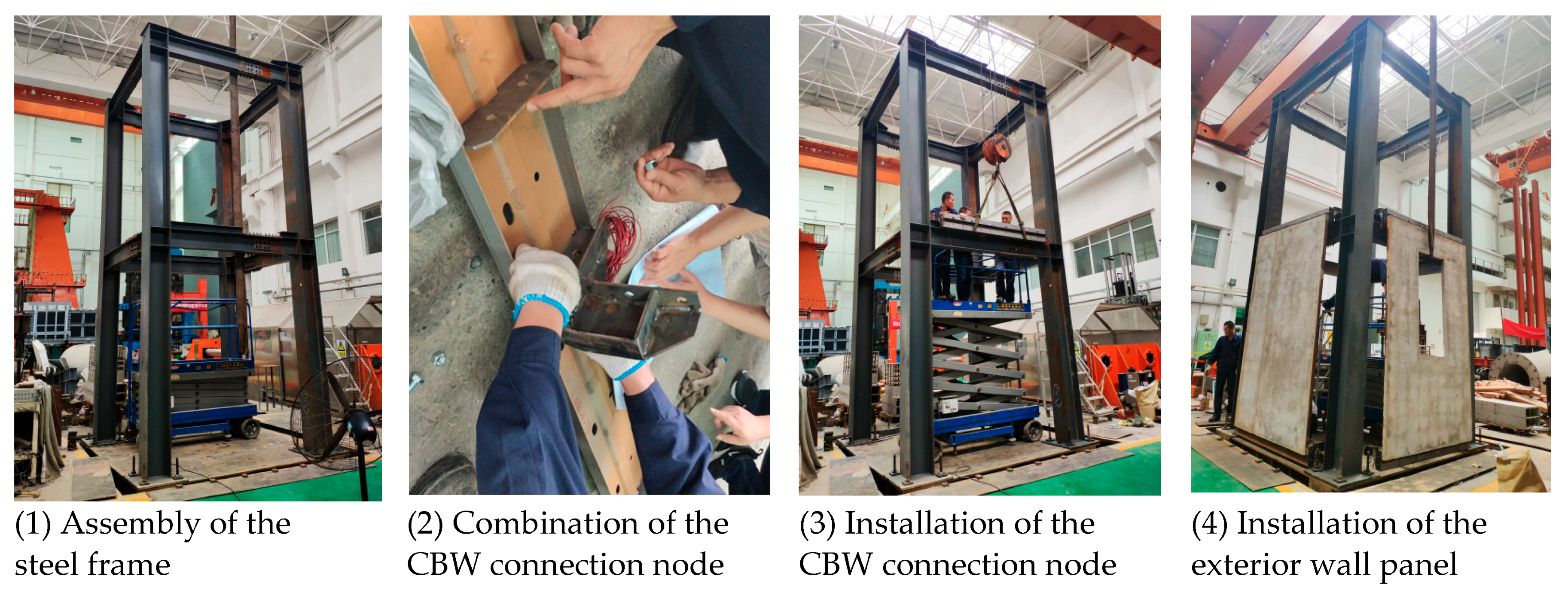
2.4. Test Setup and Instrumentation
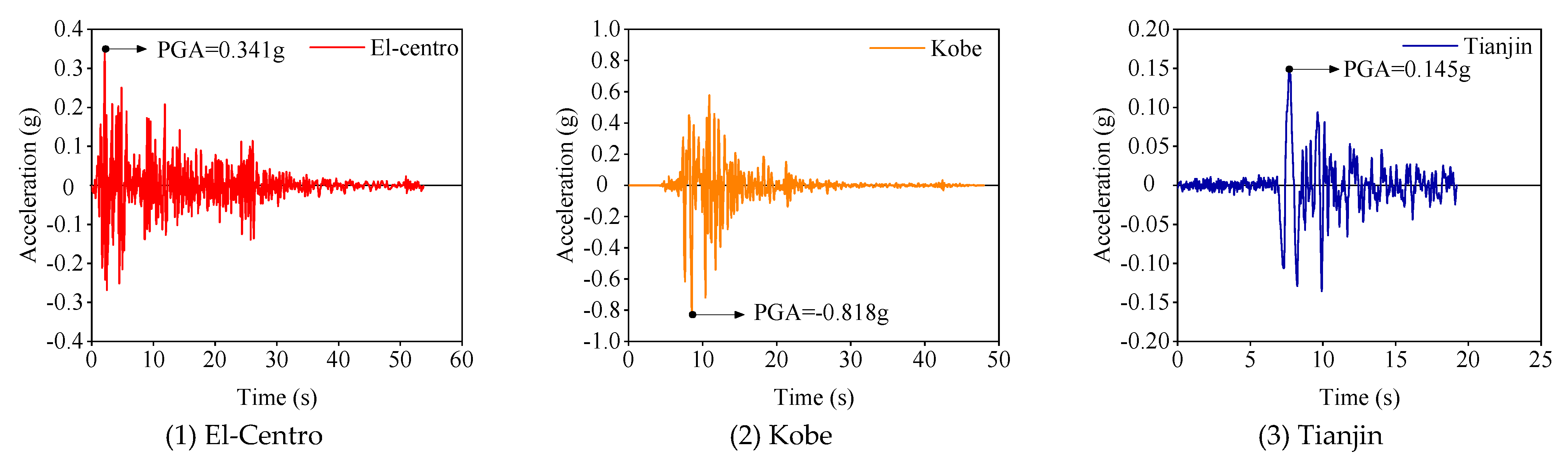
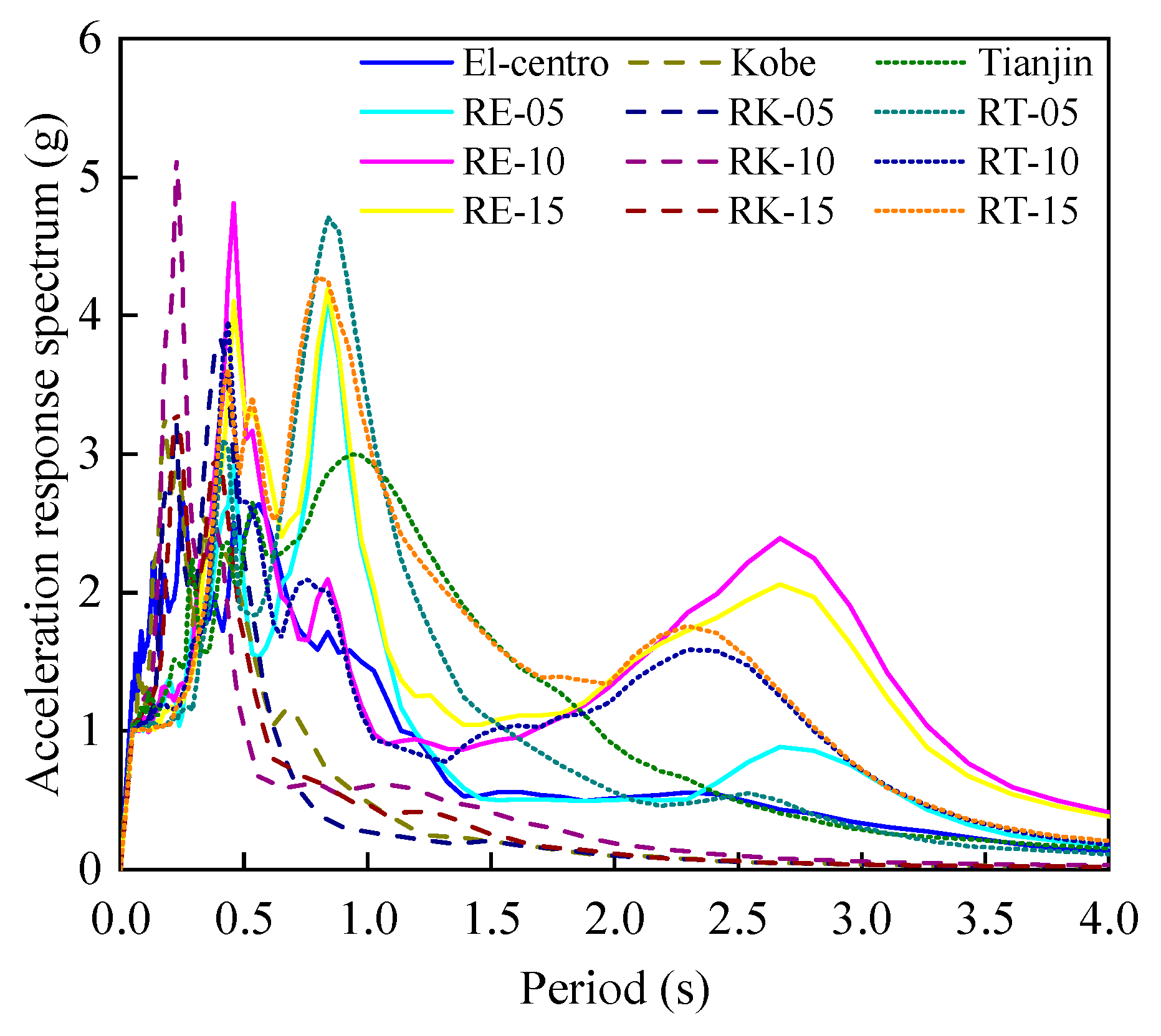
The experiment was conducted in the structural test hall at the Beijing University of Technology utilising a 3 m × 3 m shaking table that was shaken solely along the east–west axis. The table had a maximum working load of 10 t and a maximum displacement of less than 100 mm. To measure the seismic response of the test model, 25 acceleration sensors, 9 displacement sensors, and 33 strain gauges were installed, as shown in Figure 6. Two acceleration sensors (A-1 and A-2) were placed on the shaking-table surface to measure the seismic motion precisely. Acceleration sensors were positioned on the steel-frame beams on each storey, as follows: on the exterior wall panel at the same height as the steel-frame beam, and at the centre of the exterior wall panel to study the acceleration amplification of the exterior wall panel relative to the steel frame. Displacement gauges were placed between the exterior wall panels and the steel beam to calibrate the displacements derived from the acceleration integral. Additionally, vertical strain gauges were positioned at the centre of each exterior wall panel, and transverse strain gauges were placed on the diagonal plate of each cantilever block to measure the maximum strain response. The locations of all measurement points are listed in Table 2.

3. Inputs

Three representative groups of natural seismic waves (El-Centro (1940, NS), Kobe (1995, NS), and Tianjin (1976, EW)) were selected for the time–history response analysis of the 15-storey prefabricated building prototype. The time–history acceleration of the three natural seismic waves curves is depicted in Figure 7. The floor seismic responses of selected floors (floors 5, 10, and 15) of the prototype building structure under three natural waves were extracted from the results of the time course analysis. Three natural seismic waves and nine floor seismic responses were used as inputs for the shaking-table tests. The order and numbering of the inputs are listed in Table 3, and the response spectrum is shown in Figure 8.
To account for the unidirectional vibration limitation of the shaking table and to consider both the in-plane and out-of-plane movements of the exterior wall panels during earthquakes, the tests were divided into two groups. The first group of tests involved out-of-plane motion for the test composite wall panel SP-1 and integral wall panel SP-3, whereas in-plane motion was applied to test the open window wall panel SP-2, and the test model is shown in Figure 5 (1). After confirming the structural integrity of the first group of test models, the second group of tests was conducted. In this group, in-plane motion was applied to test the SP-1 and integral wall panel SP-3, whereas out-of-plane motion was applied to test the open window wall panel SP-2, and the test model is shown in Figure 5 (2).
The Chinese seismic design code specifies that the peak accelerations of seismic waves corresponding to infrequent earthquakes of seismic intensities 7, 8, and 9 are 0.22 g, 0.4 g, and 0.62 g, respectively. To simulate the seismic effects of infrequent earthquakes of seismic intensities 7, 8, and 9, amplitude modulation was applied to the input shaking tables at 0.22, 0.4, and 0.62 g, respectively. To determine the model’s natural frequency, a white noise excitation with a peak acceleration of 0.01 g was introduced with each change in the input acceleration degree. The test conditions were consistent for both groups, with each degree of input following the numbering sequence listed in Table 3 for ground-shaking. Eighty working conditions were used in the two sets of tests, including white noise input before and after loading at each stage.

4. Results and Discussion

4.1. Experimental Observations

Similar phenomena were observed in both test models. The dynamic response of the exterior wall panel increased with increasing seismic acceleration. Moreover, the vibration was most evident at the centre of the wall panel on the second floor. For the same exterior wall panel, the restrained acceleration response of the wall panel at the connection node position was smaller, whereas the acceleration response at the centre of the panel was larger. After the earthquake, no exterior wall panel shedding or damage to the CBW flexible connector was observed. A comprehensive record of the test phenomena at different seismic intensities is presented in Table 4. The test results are shown in Figure 9.

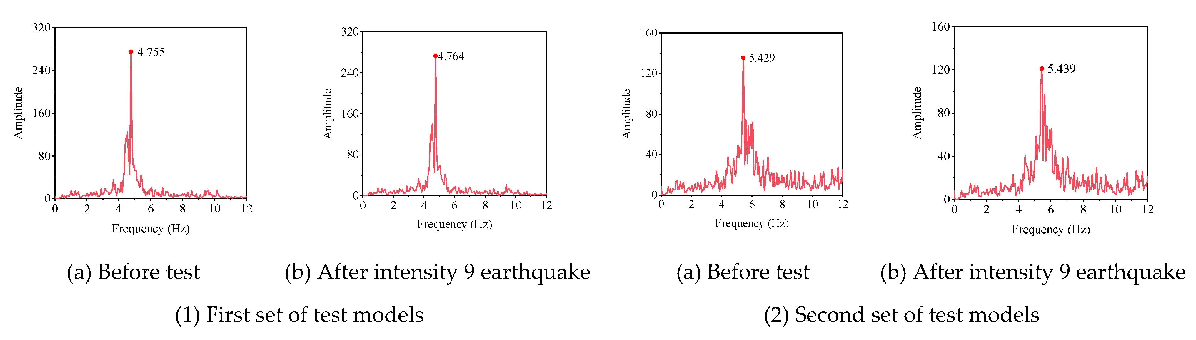
4.2. Dynamic Characteristics

The white noise was scanned before and after each earthquake simulation. The natural frequency of the model was obtained by analysing the time–history response of the acceleration sensor. The initial period of the first set of test models was 0.210 s (Figure 10 (1)), whereas the second set of test models had an initial period of 0.185 s (Figure 10 (2)). This indicated that the addition of the two exterior wall panels in the direction of shaking increased the stiffness in that direction. The natural frequency of the tested model remained relatively constant when the earthquake seismic intensity was between 7 and 9. The damping ratio was 1.60%. This indicated that the steel frame of the test model was intact.

4.3. Acceleration Response

In this study, the acceleration amplification factor α was defined as the acceleration amplification of the exterior wall panel relative to the steel frame at the same height (Equation (1)). As the seismic acceleration was transmitted to the exterior wall panel through the CBW flexible connection node, the performance of the CBW flexible connection node could be evaluated from the acceleration amplification factor as follows:
α = x m a x x m a x 0 ,
where xmax and xmax − 0 are the maximum acceleration responses measured by the accelerometers arranged on the exterior wall panel and steel frame, respectively.
The acceleration amplification factor at the centre of the wall panel was considered as the ratio of the acceleration at the centre of the wall panel to the average of the maximum acceleration values of the upper and lower steel beams.
The open window wall panel SP-2 was used as an example, and Figure 11 illustrates the acceleration response of the exterior wall panel and steel beam under the influence of the El-Centro wave. The exterior wall panel remained securely connected to the steel frame. In addition, the CBW flexible connection node proved effective in infrequent but strong seismic events up to an intensity of 9. The acceleration amplification factors of the open window wall panel SP-2 under strong earthquakes with seismic intensities of 7, 8, and 9 were 1.201, 1.212, and 1.338, respectively.
The following observations could be drawn:
(1)
In the in-plane direction, the acceleration amplification factors of the composite wall panel SP-1, open window wall panel SP-2, and integral wall panel SP-3 were found to be in the ranges of 0.881–1.304, 0.994–1.400, and 0.753–1.330, respectively, which were less than the code values (2.0 for prefabricated building elements) [21]. This indicated that the CBW flexible connection nodes had a good cushioning effect on the PC exterior wall panels.
(2)
For the out-of-plane direction, the acceleration amplification factors of the composite wall panel SP-1, open window wall panel SP-2, and integral wall panel SP-3 were found to be in the ranges of 0.998–2.094, 1.379–2.199, and 1.056–2.074, respectively.
(3)
For the exterior wall panels of the same types, the acceleration amplification factor of the exterior wall panels in the out-of-plane direction was larger than that in the in-plane direction. For the different types of exterior wall panels, the in-plane and out-of-plane acceleration amplification coefficients of the open window panel SP-2 were the largest, primarily because the in-plane and out-of-plane stiffnesses of the window panels weakened after opening the holes.

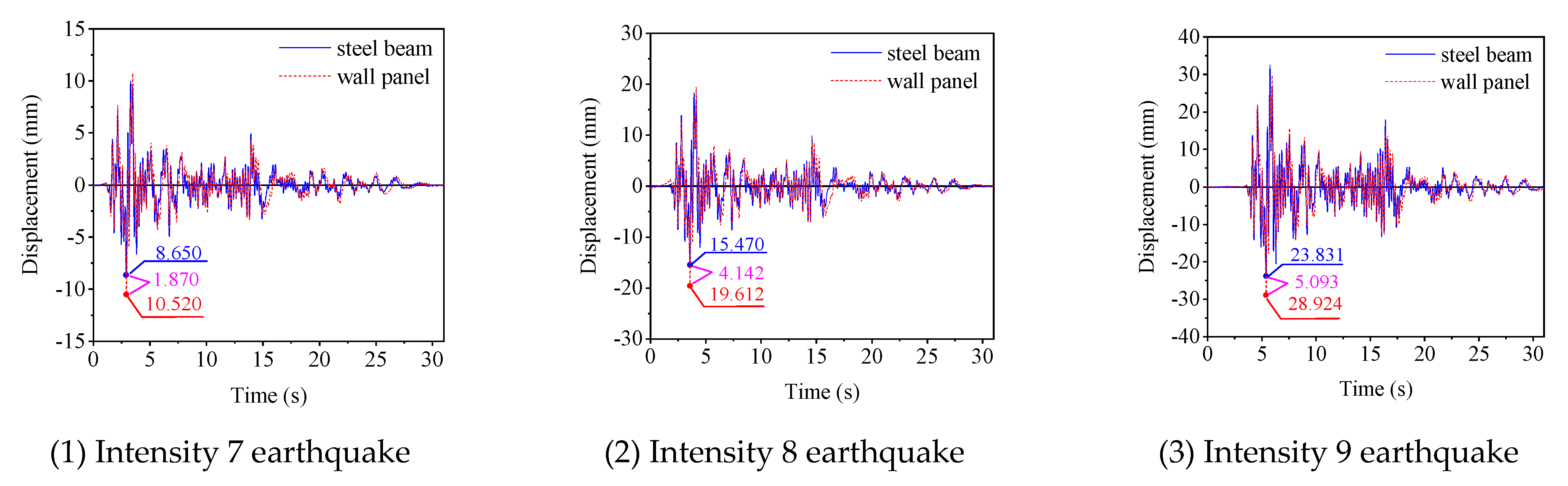
4.4. Displacement Response

The measured acceleration response was integrated to obtain the displacement response. The relative displacement β of the exterior wall panels was obtained by subtracting the steel beam displacement from the displacement of exterior wall panel, as follows:
β = |xmaxxmax − 0|,
where xmax and xmax − 0 are the maximum displacement responses obtained by integrating the acceleration responses measured by the accelerometers located on the outer wall panel and on the steel, respectively.
The relative displacement at the centre of the wall panel was defined as the difference between the displacement at the centre of the wall panel and the average of the maximum values of the displacement of the upper and lower steel beams.
The in-plane and out-of-plane relative displacements were caused by the deformation of the CBW flexible connections and the flexural deformation of the exterior wall panels. Therefore, the relative displacements reflected the condition of the CBW flexible connections and the PC exterior wall panels.
The open window wall panel SP-2 was used as an example, and the displacement responses of the exterior wall panel and steel beam under the influence of the El-Centro waves are illustrated in Figure 12. The CBW flexible connection nodes had deformation capacity. With an increase in the earthquake intensity from 7 to 9, the deformation of the CBW flexible connection node increased from 1.870 mm to 5.093 mm.
The relative displacement of the exterior wall panel increased with the seismic intensity, thus indicating an increase in the deformation of the CBW connection node. The maximum relative displacements of the composite wall panel SP-1, open window wall panel SP-2, and integral wall panel SP-3 in the plane were 3.902, 5.101, and 4.273 mm, respectively. For the out-of-plane motion, the maximum values were 2.676, 2.573, and 3.569 mm, respectively. The results indicated that the CBW flexible connection nodes provided good in-plane and out-of-plane deformation capabilities. The CBW nodes coordinated the deformation of the exterior wall panels to prevent serious damage to the exterior wall panels even under a very strong seismic intensity 9 earthquake.

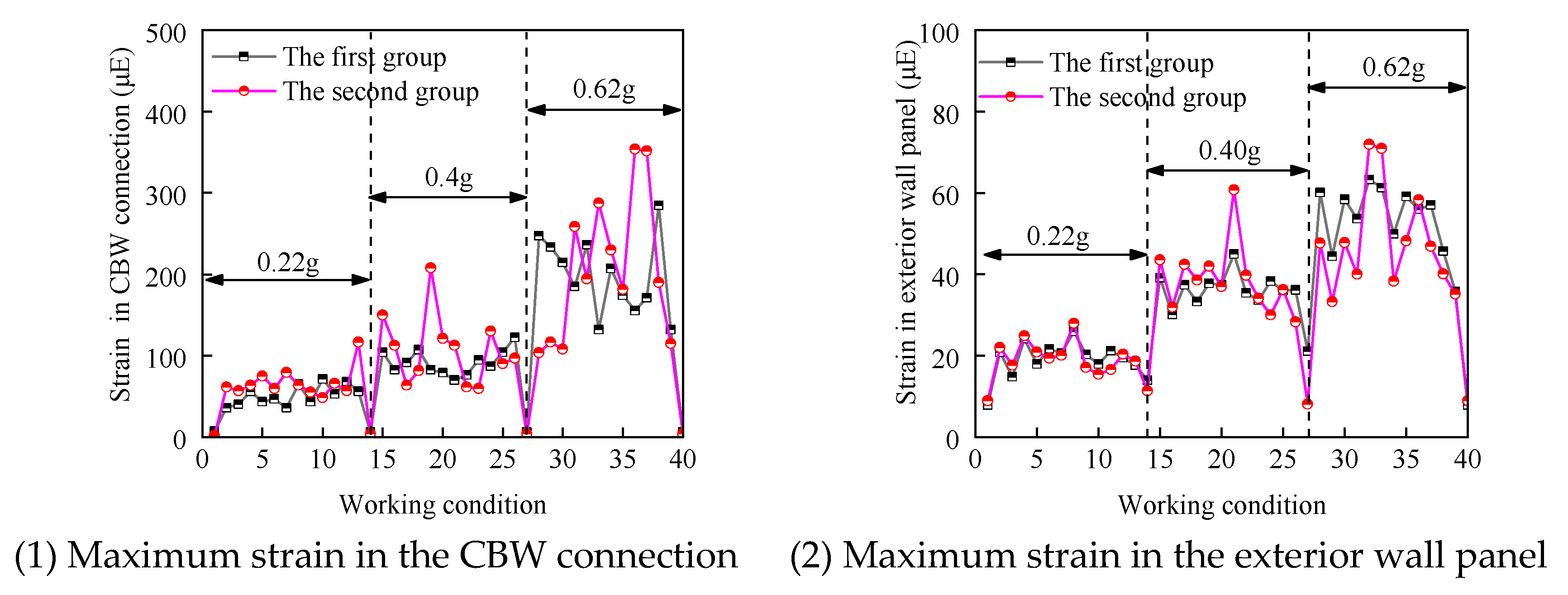
4.5. Strain Response

The strains of the exterior wall panel during the out-of-plane motion were analysed owing to their large acceleration and displacement responses. The maximum strains of the CBW flexible connection node and exterior wall panel are shown in Figure 13. As the seismic acceleration increased, both the CBW flexible connection node and exterior wall panel experienced increases in strain. For a strong seismic intensity 9 Tianjin wave earthquake, the maximum strain of the CBW flexible connector was 352 μE, which was significantly lower than the calculated yield strain of 1576 μE based on the material properties. The maximum strain of the concrete in the exterior wall panel under a seismic intensity 9 earthquake with an RK-05 floor response was 63.63 μE, which did not exceed the cracking strain of the concrete [21]. These results indicated that both the CBW flexible connection node and exterior wall panel had a significant strength capacity.

5. Conclusions

A CBW flexible connection node was proposed and shaking-table tests were conducted on a two-storey, full-scale steel frame–exterior wall panel. The acceleration, displacement, and strain responses of the three types of exterior wall panels under the action of 12 types of seismic waves of intensities of 7, 8, and 9 were analysed. The conclusions are as follows.
(1)
The flexible CBW connection nodes and the surfaces of the composite panel SP-1, open window panel SP-2, and integral panel SP-3 remained intact after intensity 7, 8, and 9 earthquakes. Only the exterior wall panels showed slight damage at the corners.
(2)
The in-plane and out-of-plane acceleration amplification coefficients of the three types of PC exterior wall panels with CBW flexible connection nodes were obtained under twelve seismic waves and three seismic intensity levels, as were the displacement amplification coefficients.
(3)
The CBW flexible connection node had a good deformation capacity that allowed it to coordinate the deformation of the exterior wall panels both in-plane and out-of-plane. This was useful for the design of other connection nodes in the project.

Author Contributions

B.Y., methodology, formal analysis, data curation, writing—original draft; Z.L., investigation, resources, supervision, funding acquisition; P.L., writing—review and editing, methodology, formal analysis; H.M., conceptualization, methodology, formal analysis, writing—review and editing; J.Y., formal analysis, project administration; Z.K., formal analysis, investigation. All authors have read and agreed to the published version of the manuscript.

Funding

This work was supported by the National Natural Science Foundation of China [grant no. 51978014].

Data Availability Statement

The data presented in this study are available on request from the corresponding author. The data are not publicly available because other research related to this area is being carried out.

Conflicts of Interest

Authors Jiulong Yang and Zhicheng Kang were employed by the company Beijing Shoushi Industrial Design Limited Company. The remaining authors declare that the research was conducted in the absence of any commercial or financial relationships that could be construed as a potential conflict of interest.

References

  1. Wang, W.; Li, Z.; Wang, W.; Li, Z.; Wang, H. A Review on the Seismic Performance of Assembled Steel Frame-Precast Concrete Facade Panels. IOP Conf. Ser. Mater. Sci. Eng. 2019, 690, 012003. [Google Scholar] [CrossRef]
  2. Baek, J.-W.; Hwang, H.-J.; Kang, S.-M.; Park, H.-G. Shaking Table Test for Dimension Stone Cladding with Dowel Pin Connection. J. Build. Eng. 2023, 70, 106390. [Google Scholar] [CrossRef]
  3. Lee, H.-S.; Oh, M.-H.; Kim, W.-S. Structural Performance of Curtain Wall Using Separate Interstorey Modules and Three-Axis Mobile Fasteners. J. Korean Soc. Adv. Comp. Struct. 2020, 11, 34–45. [Google Scholar] [CrossRef]
  4. Huang, B.; Lu, W.; Günay, S. Shaking Table Tests of Granite Cladding with Dowel Pin Connection. Bull. Earthq. Eng. 2020, 18, 1081–1105. [Google Scholar] [CrossRef]
  5. Ding, K.; Zong, D.; Liu, Y.; He, S.; Shen, W. Experimental and Finite Element Analysis of External ALC Panel Steel Frames with New Semi-Rigid Connector. Appl. Sci. 2021, 11, 10990. [Google Scholar] [CrossRef]
  6. Song, Z.; Zhou, Y.; Lu, Y. Shaking table test of a 10-storey self-centering tube building. Earthq. Eng. Struct. Dyn. 2023, 52, 1511–1535. [Google Scholar] [CrossRef]
  7. Huang, Z.; Chen, Z.; Huang, D.; Chui, Y.-H. Cyclic Loading Behavior of an Innovative Semi-Rigid Connection for Engineered Bamboo-Steel Hybrid Frames. J. Build. Eng. 2019, 24, 100754. [Google Scholar] [CrossRef]
  8. Li, Y.; Gao, C.; Yan, Y.; Ning, Z. Experimental Study on the Seismic Performance of Steel Frames with Infill ALC Wall Panels. J. Build. Eng. 2023, 65, 105739. [Google Scholar] [CrossRef]
  9. Wang, J.; Shen, Q.; Li, B. Seismic Behavior Investigation on Blind Bolted CFST Frames with Precast SCWPs. Int. J. Steel Struct. 2018, 18, 1666–1683. [Google Scholar] [CrossRef]
  10. Wang, J.; Li, B. Cyclic Testing of Square CFST Frames with ALC Panel or Block Walls. J. Constr. Steel Res. 2017, 130, 264–279. [Google Scholar] [CrossRef]
  11. De Matteis, G. Effect of Lightweight Cladding Panels on the Seismic Performance of Moment Resisting Steel Frames. Eng. Struct. 2005, 27, 1662–1676. [Google Scholar] [CrossRef]
  12. Zhenggang, C.; Peng, D.; Feng, F.; Ming, F. Cyclic Testing and Parametric Analyses of the Fabricated Steel Frames Infilled with Autoclaved Aerated Concrete Panels. Adv. Struct. Eng. 2017, 20, 629–640. [Google Scholar] [CrossRef]
  13. Gokmen, F.; Binici, B.; Taghipour, A.; Canbay, E. Seismic Behavior of Autoclaved Aerated Concrete Low Rise Buildings with Reinforced Wall Panels. Bull. Earthq. Eng. 2019, 17, 3933–3957. [Google Scholar] [CrossRef]
  14. Wang, B.; Wang, J.; Gong, X.; Liu, B. Experimental Studies on Circular CFST Frames with ALC Walls under Cyclic Loadings. Int. J. Steel Struct. 2014, 14, 755–768. [Google Scholar] [CrossRef]
  15. Vaghei, R.; Hejazi, F.; Firoozi, A.A. Analytical Model for Precast Wall Equipped with U-Shaped Steel Channel Connection. Structures 2021, 32, 406–432. [Google Scholar] [CrossRef]
  16. Liu, R.; Zhang, K.; Tao, M. Test Study on Slipping Performance of the Flexible Nodes of the Precast Concrete Exterior Wall Cladding Panel. Adv. Mater. Res. 2014, 940, 284–288. [Google Scholar] [CrossRef]
  17. Du, D.; Wang, S.; Li, W.; Xu, F.; Liu, W. Seismic Performance of the Pre-Fabricated Steel Frame Infilled with AAC Wall Panels and Their Joint Connection: Full-Scale Shaking Table Test. J. Earthq. Tsunami 2019, 13, 1940004. [Google Scholar] [CrossRef]
  18. Cui, J.; He, S.; Ding, K.; Zhang, Y.; Kong, X. Cyclic Behavior of Autoclaved Aerated Concrete External Panel with New Connector. Materials 2022, 15, 8778. [Google Scholar] [CrossRef] [PubMed]
  19. Fang, M.-J.; Wang, J.-F.; Li, G.-Q. Shaking Table Test of Steel Frame with ALC External Wall Panels. J. Constr. Steel Res. 2013, 80, 278–286. [Google Scholar] [CrossRef]
  20. GB/T 51232-2016; Technical Standard for Assembled Buildings with Steel-Structure. Ministry of Housing and Urban-Rural Development of the People’s Republic of China: Beijing, China, 2016. (In Chinese)
  21. GB 50010-2010; Code for Design of Concrete Structures. China Building Industry Press: Beijing, China, 2015. (In Chinese)
  22. JGJ/T 458—2018; Application Technical Standard of Precast Concrete External Wall Panel. China Building Standards Design and Research Institute Co., Ltd.: Beijing, China; China Resources Land Co., Ltd.: Hong Kong, China; China Architecture and Building Press: Beijing, China, 2018. (In Chinese)
  23. GB50017–2017; Standard for Design of Steel Structures. Ministry of Housing and Urban-Rural Development of the People’s Republic of China: Beijing, China, 2017. (In Chinese)
  24. GB/T 228.1-2010; Metallic Materials-Tensile Testing—Part 1: Method of Test at Room Temperature. General Administration of Quality Supervision, Inspection and Quarantine of the People’s Republic of China: Beijing, China, 2010. (In Chinese)
  25. GB/T 50081-2019; Standard for Test Method of Mechanical Properties on Ordinary Concrete. China Building Industry Press: Beijing, China, 2019. (In Chinese)
  26. GB/T 3098.1–2010; Mechanical Properties of Fasteners Bolts, Screws and Studs. State Administration for Market Regulation: Beijing, China, 2010. (In Chinese)
Figure 1. The flow diagram for the research.
Buildings 14 00634 g001
Figure 2. CBW flexible connection node.
Buildings 14 00634 g002
Figure 3. Size of CBW flexible connection node.
Buildings 14 00634 g003
Figure 4. Assembly process of the test model.
Buildings 14 00634 g004
Figure 5. The two sets of test models.
Buildings 14 00634 g005
Figure 6. Instrumentation arrangement.
Buildings 14 00634 g006
Figure 7. Time–history curves.
Buildings 14 00634 g007
Figure 8. Response spectrum of the 12 inputs.
Buildings 14 00634 g008
Figure 9. Test phenomena.
Buildings 14 00634 g009
Figure 10. Natural frequencies of the tested model.
Buildings 14 00634 g010
Figure 11. Acceleration on the SP-2 exterior wall panel and steel beam under the El-Centro wave in the first set of tests.
Buildings 14 00634 g011
Figure 12. Relative displacements of the SP-2 exterior wall panels and steel beams under the El-Centro wave in the first set of tests.
Buildings 14 00634 g012
Figure 13. Maximum strain responses of the exterior wall panels (out-of-plane).
Buildings 14 00634 g013
Table 1. Material properties.
Es or Ec (MPa)fy (MPa)fu (MPa)fcu (MPa)fc (MPa)ft (MPa)
Q345 steel206,000360.96487.66
Q235 steel205,000323.14460.25
Concrete32,10537.9325.372.57
Table 2. Location and numbering of the measurement points.
SensorsLocationNumber (Quantity)No.
Acceleration sensorsShaking table 2 A-1, A-2
Each storey’s steel-frame beam6AK-1, AK-2, AK-3, ..., AK-6
Exterior wall panel at the height of the storey9AC-1, AC-3, AC-5, AW-1, AW-3, AW-5, AI-1, AI-3, AI-5
The centre of the exterior wall panel8AC-2, AC-4, AC-6, AC-7, AW-2, AW-4, AI-2, AI-4
Displacement sensorsBetween the exterior wall panel and the steel beam9DC-1, DC-2, DC-3, DW-1, DW-2, DW-3, DI-1, DI-2, DI-3
Strain gaugesThe centre of the exterior wall panel 6SC-1, SC-2, SW-1, SW-2, SI-1, SI-2
The cantilever block27SN-1, SN-2, SN-3, ..., SN-27
Table 3. Numbering sequence of the inputs.
Order123456789101112
NumberingEl-CentroRE-05RE-10RE-15KobeRK-05RK-10RK-15TianjinRT-05RT-10RT-15
Table 4. Descriptions of the test phenomena.
Seismic IntensityDuring TestAfter Test
7
(0.22 g)
The exterior wall panels followed the movement of the steel frame.The exterior wall panels were in good surface condition.
8
(0.4 g)
The centre of the exterior wall panel (out-of-plane movement) protruded, with sound when the wall panel collided with the steel frame.The concrete surface at the connection between the exterior wall panel and the CBW flexible connection node cracked (Figure 9).
9
(0.62 g)
The centre of the exterior wall panel (out-of-plane movement) protruded significantly (Figure 9), and the sound was louder.The surface of the exterior wall panel was largely intact, with slightly broken concrete at the corners. The CBW flexible connection node remained intact.
Disclaimer/Publisher’s Note: The statements, opinions and data contained in all publications are solely those of the individual author(s) and contributor(s) and not of MDPI and/or the editor(s). MDPI and/or the editor(s) disclaim responsibility for any injury to people or property resulting from any ideas, methods, instructions or products referred to in the content.

