Article

Simulation Analysis of the Structure of an Integrated Modular House by Flat Pack Based on the Elastic–Plastic Contact Theory and Experimental Study of Its Corner Fitting Joint

1
Institute of Defense Engineering, AMS, PLA, Beijing 100850, China
2
School of Mechanical and Vehicle Engineering, Beijing University of Civil Engineering and Architecture, Beijing 100044, China
3
Beijing Engineering Research Center of Monitoring for Construction Safety, Beijing 100044, China
*
Authors to whom correspondence should be addressed.
Buildings 2024, 14(3), 635; https://doi.org/10.3390/buildings14030635
Submission received: 27 November 2023 / Revised: 6 February 2024 / Accepted: 16 February 2024 / Published: 28 February 2024
(This article belongs to the Section Building Structures)

Abstract

:
Based on the elastic–plastic contact theory, elastic–plastic contact finite element models for the integrated modular house by flat pack are established. The structural stress and displacement distributions are obtained. An experimental test is conducted to study the performance of the corner fitting joint of the house. The finite element analysis and experimental test comprehensively demonstrated the safety and reliability of the house structure. The results show that the most unfavorable stress point of the house is located at the corner fitting joint. When the end plate connection holes of the corner column seal are designed with through holes and internal screw holes, respectively, the fastening effect of bolting between the corner fitting and corner column using the internal screw hole is better. The reliability of the repeated disassembly and assembly of the house is verified via multiple loading–unloading simulation cycle experiments of the corner fitting joint. The results of the study provide technical support and a reference basis for the optimal design and ensuring the service performance of the integrated modular house by flat pack.

1. Introduction

Integrated modular house by flat pack is a light steel structure with modular design, factory fabrication, packaged transportation, and on-site modular assembly, as shown in Figure 1. Its characteristics include rapid disassembly, modular combination, re-usability, efficient transportation, and green and environmentally friendly [1,2,3]. Therefore, they are extensively utilized in scenarios such as emergency rescue, military deployment, and construction operations [4,5,6,7].
However, the absence of established standards and norms in the realm of prefabricated buildings highlights the necessity of delving into their mechanical properties. This exploration is crucial for advancing the field of prefabrication in architecture [8]. Over the past few years, a significant number of researchers have devoted efforts to studying this area, using a diverse range of research methods.
Among them, the experimental approach is extensively employed due to its appropriateness for practical engineering scenarios and its ability to yield clear results. For instance, Dai Mingming conducted field experiments to examine the dynamic properties of prefabricated cold-formed thin-walled light steel movable plate houses [9]. Yoshihide Tominaga assessed the impact of wind load on double-sloping roofs using wind tunnel experiments [10]. Similarly, Liu Y investigated the earthquake resistance of corner-supported modular steel structures by performing full-scale frame-loading tests [11]. Ma SC, via elastic loading tests, destructive tests, and low-cyclic repeated loading tests, studied the seismic performance of prefabricated integrated floor truss beams, alkali-resistant glass fiber ceramsite concrete sandwich composite shear walls, and structurally integrated insulated composite wall panel joints [12,13,14].
However, experimental investigations often face several constraints, such as limited location conditions and challenges in forecasting structural deformation trends. These challenges can be effectively overcome via numerical analysis and finite element simulations. For example, Li Sheng investigated the dynamic properties of a light steel movable plate house using the free vibration attenuation method combined with finite element simulation [15]. Lin Hsin-Hung examined the effect of ventilation airflow on a container room using simulation analysis and numerical calculations [16]. Fan Kunjie conducted an analysis of the lateral stiffness of the side plate of a container house employing skin theory [17].
The bolted connection is typically used between the corner fitting of the structure, which is often considered a semi-rigid connection. For semi-rigid connections, the research methods are divided into the following four kinds. Firstly, a spring element without length is utilized to simulate the flexibility of connection and analyze the nodes in an elastic manner [18,19]. Secondly, finite element models of semi-rigid connections are established to calculate the stress conditions [20,21,22,23,24]. The third one is to modify the traditional theoretical method for a specific structure with a semi-rigid connection [25,26,27,28]. The fourth one is to analyze the load–displacement relationship of a semi-rigid connection based on test data [29,30,31,32,33,34,35]. Although the connections of the integrated modular house by flat pack are generally analyzed using the semi-rigid connection method in previous studies, the force transfer mechanism and the mechanical properties of connections considering the contact mechanics have not been reported.
Therefore, to effectively address joint contact and overcome the limitation of oversimplifying this kind of joint in current finite element simulations, refined finite element models of the integrated modular house by flat pack structures are established, and the connections are simulated based on elastic–plastic contact theory to analyze the stress and displacement of the house under different loading conditions. Additionally, experimental tests on the corner column of the house are carried out. The weld strength of the corner fitting joint is validated, and the repeated disassembly performance of the corner fitting joint is investigated. Based on the above research, the safety and reliability of the assembled house structure are comprehensively verified, providing a practical basis for the optimization of the house structure.

2. Elastic–Plastic Contact Theory and Penalty Function Method

Both elastic–plastic and contact theories involve boundary undetermined problems. When subjected to a load, both elastic and plastic zones may be produced inside a structure [36]. For the semi-rigid connections of the integrated modular house by flat pack, the force transfer process is relatively complicated. The actual contact condition between corner fittings and corner columns can hardly be defined quantitatively and precisely. To better reflect the real internal force and deformation of the structure, the finite element analysis of integrated modular house by flat pack is carried out based on the elastic–plastic contact theory.
Elastic–plastic contact requires discretization of the contact interface. It is assumed that a pair of contact blocks, including active contact blocks and passive contact blocks, is called a contact pair, and the corresponding nodes are defined as A and B, respectively shown in Figure 2, and M and N in finite element coordinates, respectively. The contact surface is assumed to be a two-dimensional plane, and the active contact block is a 4-node element. The point T on the active contact block (independent of the element) and the point L on the passive contact block are selected, and the relative displacement u between them is calculated according to Formula (1).
u A u B = N c u c
The matrix form of u c is [ u K T   u 1 T   u 2 T   u 3 T   u 4 T ] .
N c is the unit interpolation function, and the matrix form is [ I N 1 N 2   N 3   N 4 ] , where I is a 3 × 3 unit matrix. The coordinates in the local coordinate system can be obtained by transforming the coordinates of Formula (1), as shown in Formula (2).
u M u N = θ T t + Δ t ( u A u B ) = θ T t + Δ t N c u c
θ is the transformation of the matrix for the coordinate system. It is expressed by the projection components of the vector e J in the Cartesian coordinate system along the three directions of x, y, and z. (J = 1, 2, 3, i = x, y, z)
θ = e 1   e 2   e 3 = e 1 x e 2 x e 3 x e 1 y e 2 y e 3 y e 1 z e 2 z e 3 z
The expression of virtual work carried out by the surface contact force acting on the contact surface can be converted into discrete form after processing, that is,
W c t + Δ t = k = 1 n c W c t + Δ t k
In the formula, n c is the number of contact pairs, and W c k is the virtual work carried out by each contact point to the equivalent stress.
W c t + Δ t k = F J M t + Δ t ( δ u J M δ u J N ) k = ( δ u J M δ u J N ) T t + Δ t F M k
In the formula, F M t + Δ t represents the equivalent contact force corresponding to the k th contact pair in the local coordinate system.
By substituting Formula (2) into Formula (5), you can obtain the following:
W c t + Δ t k = δ u c T N c T   t + Δ t θ t + Δ t F M k
δ u c has a certain arbitrariness, so the expression of the equivalent node contact force vector acting on the k th contact pair is as follows:
Q c t + Δ t k = N c T   t + Δ t θ t + Δ t F A k = Q P T t + t Q 1 T t + t Q 2 T t + t Q 3 T t + t Q 4 T t + t T
In the formula, QP, Q1, Q2, Q3, and Q4 are the equivalent contact force vectors acting on the corresponding node.
After discretizing the contact surface, the elastic–plastic contact equation can be solved using a penalty function. The penalty function method is a standard optimization algorithm considering constraints, often used to solve extremum problems for generalized functions. The contact problem addressed in this work is a constraint condition, and the expression of the contact force vector of the penalty function is shown in Equation (8).
The following is example 8 of an equation:
Π = Π u + Π C P
where Πu is the function for potential energy, and ΠCP is the penalty function.
When the contact surfaces are in a state of friction and relative sliding, δΠCP could be obtained by adding the corresponding constraint conditions, and the solution equation needs to make δΠ to be 0. The δΠu could be solved by the virtual work equation. Finally, the contact force of point pairs on the contact interface is obtained, and the equivalent nodal contact force vector corresponding to the whole system could be obtained by integrating all contact point pairs.

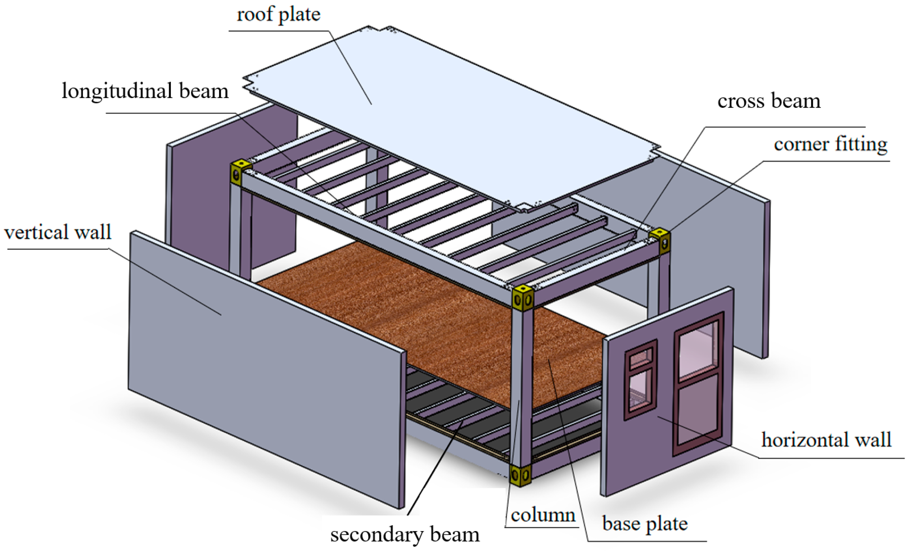
3. Structural Composition of Integrated Modular House by Flat Pack

The integrated modular house by flat pack is mainly composed of the roof system (including the roof plate, roof frame, and corner fitting), the floor system (including the base plate, floor frame, and corner fitting), corner columns, wallboard, and other components, as shown in Figure 3.
The size of the integrated modular house by flat pack studied in this work is 6000 mm × 3000 mm × 3000 mm (length × width × height). Square thin-walled steel shapes are used as vertical and cross beams and corner columns. The corner column has dimensions of 220 mm × 9 mm (width × thickness), and the cross-sectional dimensions of the longitudinal beam and cross beam of roof and floor frames are 250 mm × 150 mm × 7 mm (width × height × thickness). The sub-beams are made of channel steel with a cross-section of 120 mm × 60 mm × 7 mm (height × leg width × waist thickness). The beams, columns, and corner fitting are all made of Q345 steel, and the wall panels are made of sandwich boards with metal surfaces and polyurethane cores.
The design of the bolted connection at the corner fitting and its schematic diagram are shown in Figure 4 and Figure 5, respectively. The bolt holes of the corner fitting and the inner threaded holes of the corner column are fastened by eight M20 bolts (grade 8.8), and the main beam and the extension plate of the corner fitting are fastened by six M16 bolts (grade 8.8). The plate thickness of the corner fitting is 14 mm, and the length of its extension plate is 250 mm. The diameter of the bolt hole connecting the corner column is 22 mm, and the diameter of the bolt hole connecting the main beam is 18 mm. According to the design principles of “strong joint and weak member” and “strong column and weak beam”, the beam–column connection joint is the key force transfer component of the structure. Thus, the mechanical performance of those joints has a significant impact on the structure design of the house [37,38,39,40].

4. Simulation Analysis of Integrated Modular House by Flat Pack

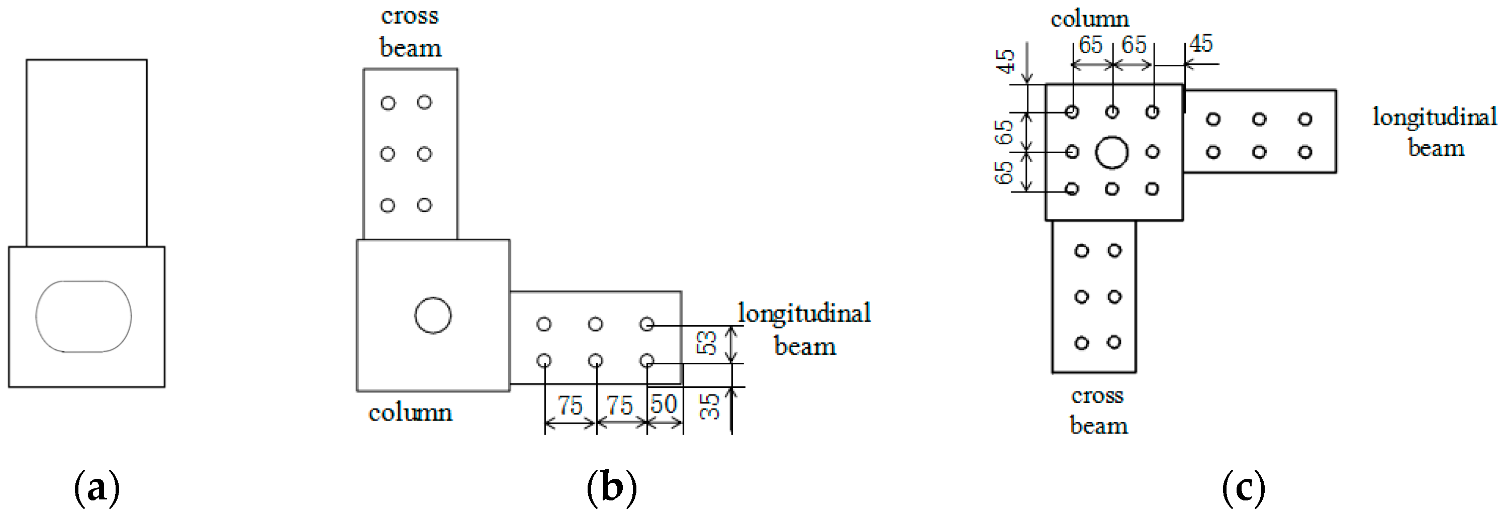
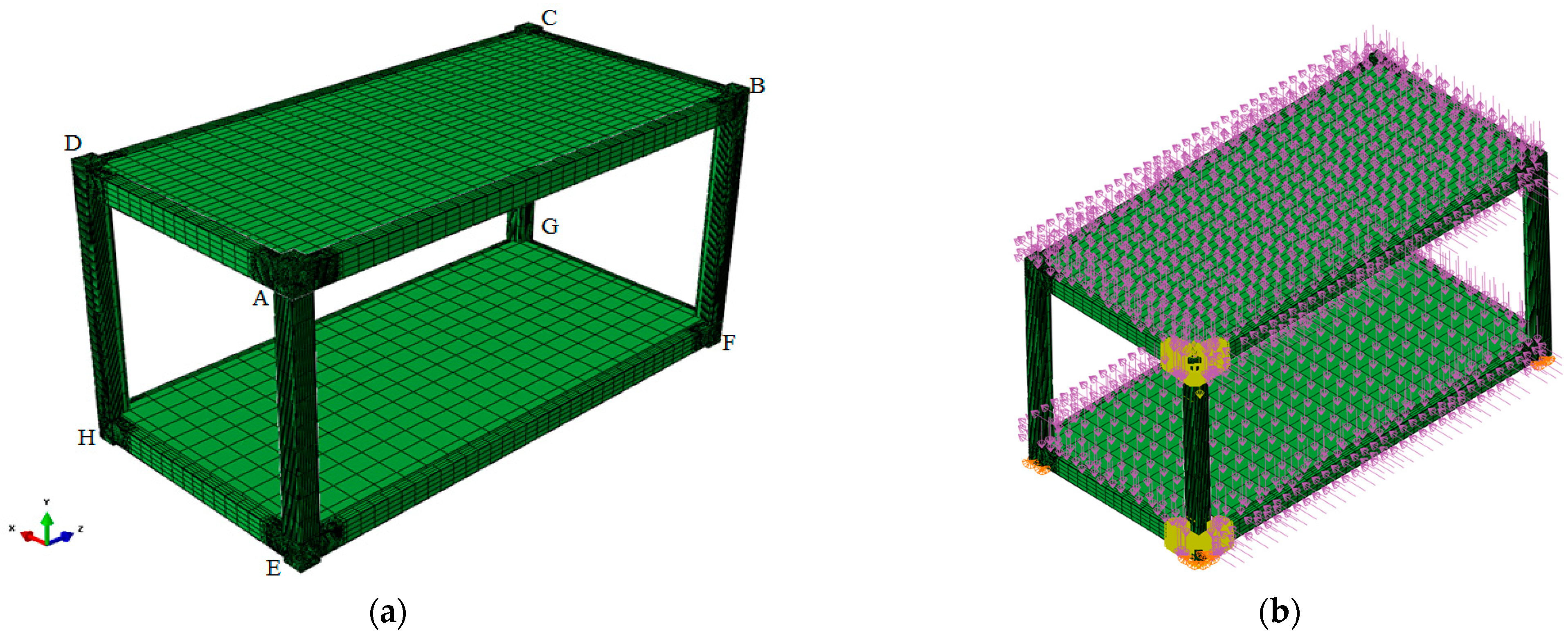
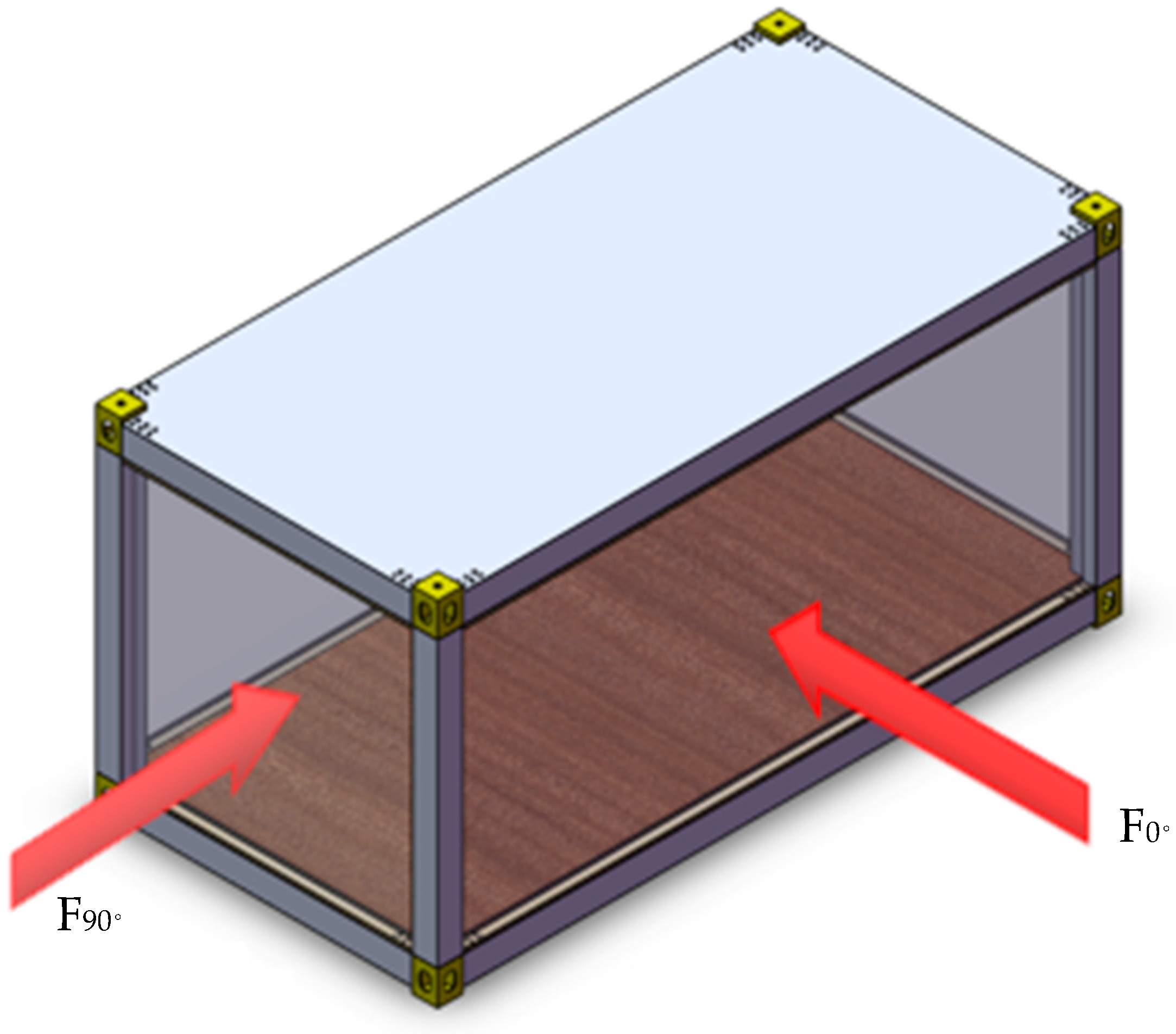
4.1. Finite Element Modeling

The finite element model of the integrated modular house by flat pack was established using ABAQUS version 2019, as shown in Figure 6. And the letters A–H stand for the joints of the corners. The model adopts a non-conforming mode eight-node hexahedron element (C3D8I element); the additional degree of freedom of the enhanced element displacement gradient is introduced into the linear element, which can overcome the shear self-locking problem in linear complete integration and has high calculation accuracy. Additionally, the calculation time could be saved simultaneously.
According to Saint-Venant’s principle, the stresses in a body caused by loads distributed over an elastic body are essentially related only to the resultant force and the resultant moment of the loads at a distance slightly away from the loaded area. Therefore, to reduce the computational load of the model while ensuring the reasonableness and accuracy of the calculation and analysis, the contact conditions are adopted only for the corner fitting A and E with corner columns and main beams to reduce the calculation cost. The other corner fittings, columns, and beams are simulated as continuum components without contact conditions. In the finite element model, there are 145,781 nodes and 109,719 elements.
Simultaneously, full restraints are applied to the bottom corners (E, F, G, and H) of the integrated modular house by flat pack. The force analysis of the integrated modular house by flat pack is carried out considering four loading conditions, as shown in Table 1. Conditions 1 and 3 considered only the vertical design load, while conditions 2 and 4 considered both vertical load and wind load.
According to Load code for the design of building structures (GB 50009-2012) [41], the standard values for floor dead load, roof dead load, floor live load, and roof live load are 1.0 kN/m2, 0.2 kN/m2, 5.0 kN/m2, and 2.0 kN/m2, respectively.
The wind angles of 0° and 90° are shown in Figure 7. The analysis shows that the effect of 0° wind load is more disadvantageous. Consequently, only the 0° wind load is considered. Regarding the standard value of wind load, the windward side is 1.36 kN/m2, the leeward side is −0.85 kN/m2, the roof surface is −0.34 kN/m2, and both sides are −1.19 kN/m2 (positive value indicates wind thrust, and negative value indicates wind suction).

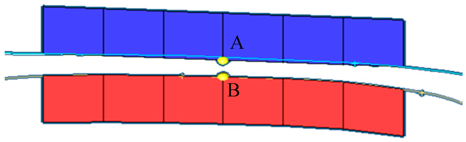
4.2. Analysis for Integral Deformation and Equivalent Stress

Table 2 illustrates the deformation of a house in the X, Y, and Z directions under different loading scenarios. The structure’s response to these loads, particularly due to inherent structural features and load-bearing patterns, indicates that the greatest deformation consistently occurs at the center of the wall panels. This central deformation is a critical indicator of the house’s structural behavior under stress. The displacement values are significant, especially when the wind load is present. Condition 2 shows a displacement of 6.813 mm in the X direction, and condition 4 shows 3.720 mm, highlighting the substantial influence of wind on the house’s deformation. These values are notably higher than those conditions without wind load (conditions 1 and 3), emphasizing the critical role of wind force in affecting structural integrity. The deformation measurements are given in centimeters to provide a clear and quantifiable assessment of the house’s ability to withstand various load conditions.
The equivalent stress distributions of the house under each loading condition are similar, with the maximum value being 223.0 MPa, which occurs at the connection between the longitudinal main beam and the corner fitting. Using loading condition 1 as an example, the equivalent stress cloud chart of the house is shown in Figure 8. Therefore, the maximum equivalent stress of the house under four working conditions is shown in Table 3. The yield strength of Q345 steel is 345.0 MPa, the safety factor is 1.5, and the allowable stress is 230.0 MPa. The maximum equivalent stress of the house is less than the allowable stress of the material, meeting safety requirements.
The equivalent stress near the fillet weld ranges from 64 to 88 MPa, remaining within allowable limits and meeting safety requirements.

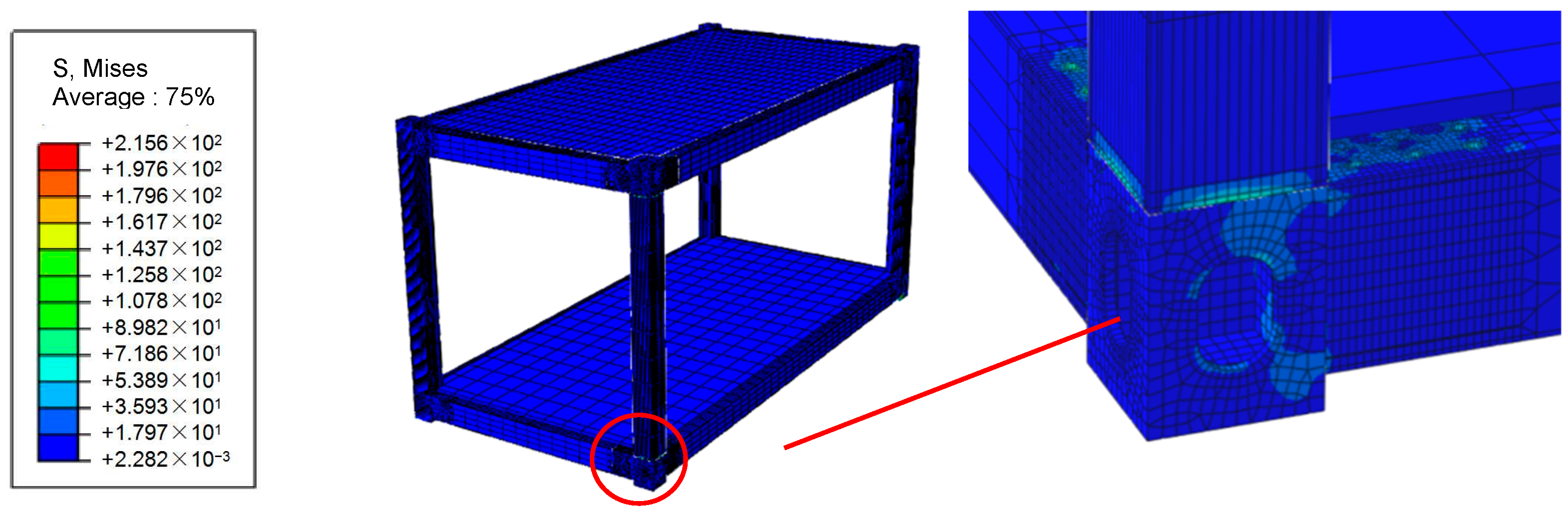
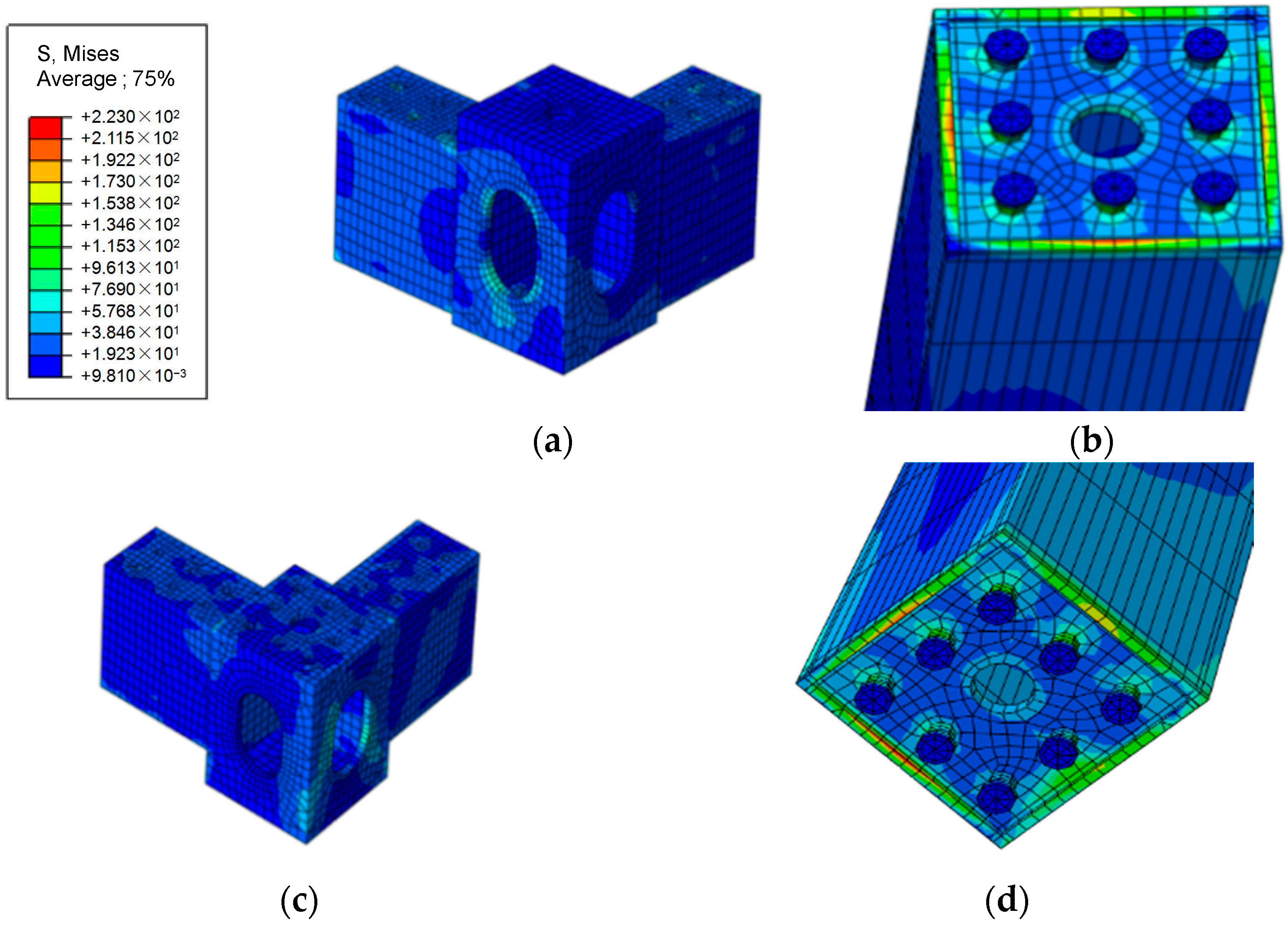
4.3. Equivalent Stress at Contact Part of Joint

In the elastic–plastic contact finite element analysis of the connection part of the corner column–corner fitting joint, the integrated modular house by flat pack under loading conditions 2 and 4 has larger stresses. Since the equivalent stress cloud charts of conditions 2 and 4 are similar, taking loading condition 2 as an example, Figure 9 shows the equivalent stress cloud chart of the upper and lower corner fitting and the upper and lower surfaces of the corner column. Under the combined action of the load transferred from the upper frame and the wind load, the corner column exhibits a larger equivalent stress on the end surface, with relatively large equivalent stress near the bolt hole.
Via simulation of the entire structure, it is determined that the stress at the connection between the corner column and the longitudinal main beam is the highest. Due to the actual limitations imposed by the structural geometry and size of the corner fitting, it is not convenient to directly use the bolt–nut connection between the corner fitting and the corner column. Instead, a threaded hole is processed on the column sealing end plate, and the fastening connection between the corner column and the corner is achieved via the bolt–thread connection. To further validate the reliability of the bolted joint, the corner fitting and corner columns are tested and analyzed.

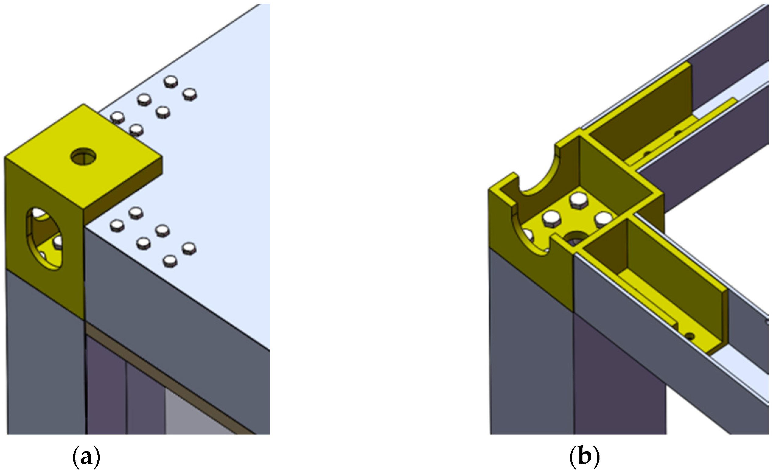
5. Experimental Study on Corner Column–Corner Fitting Joint

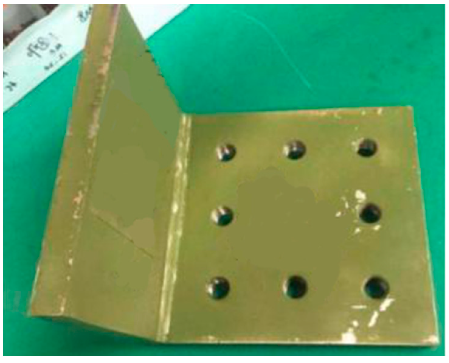
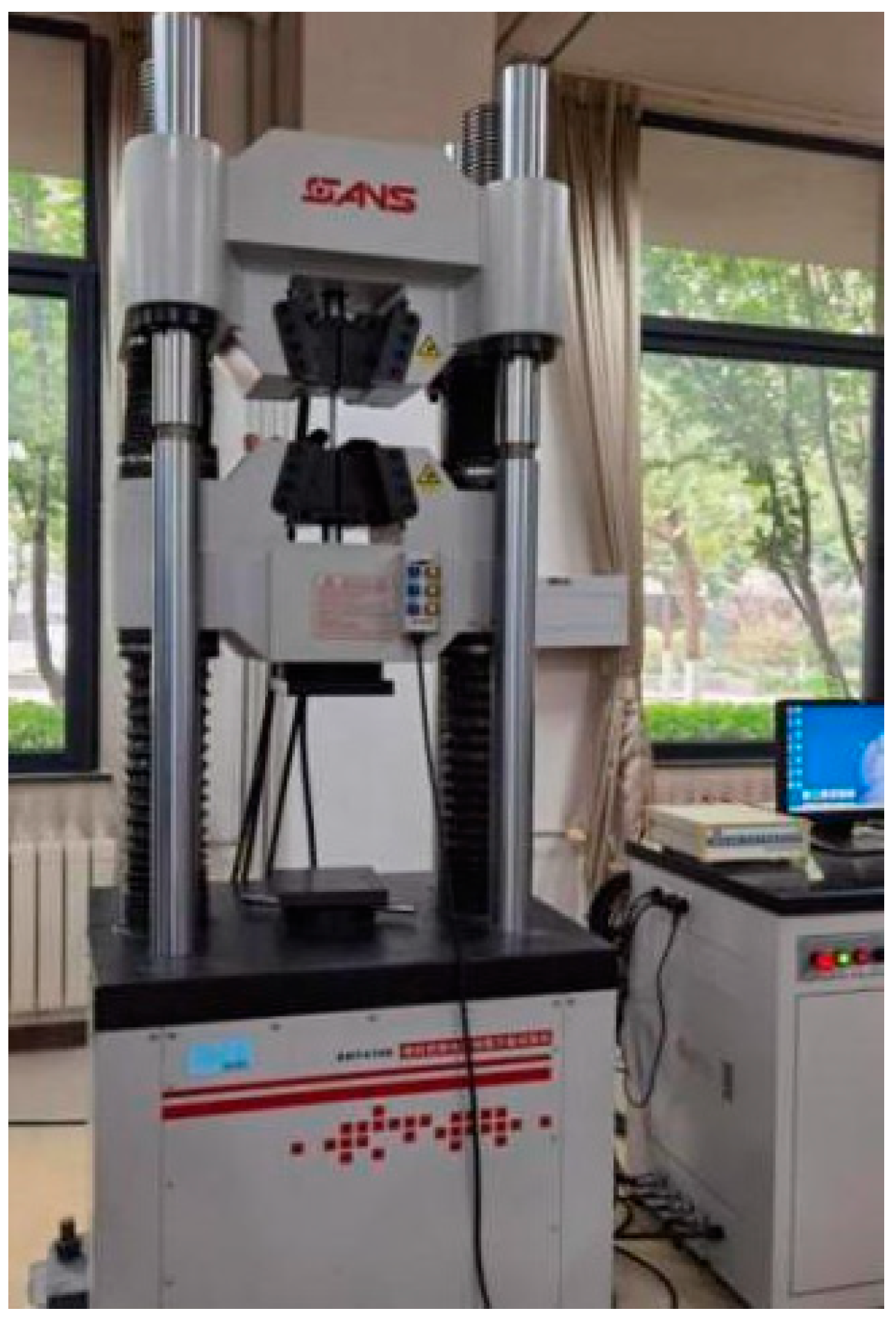
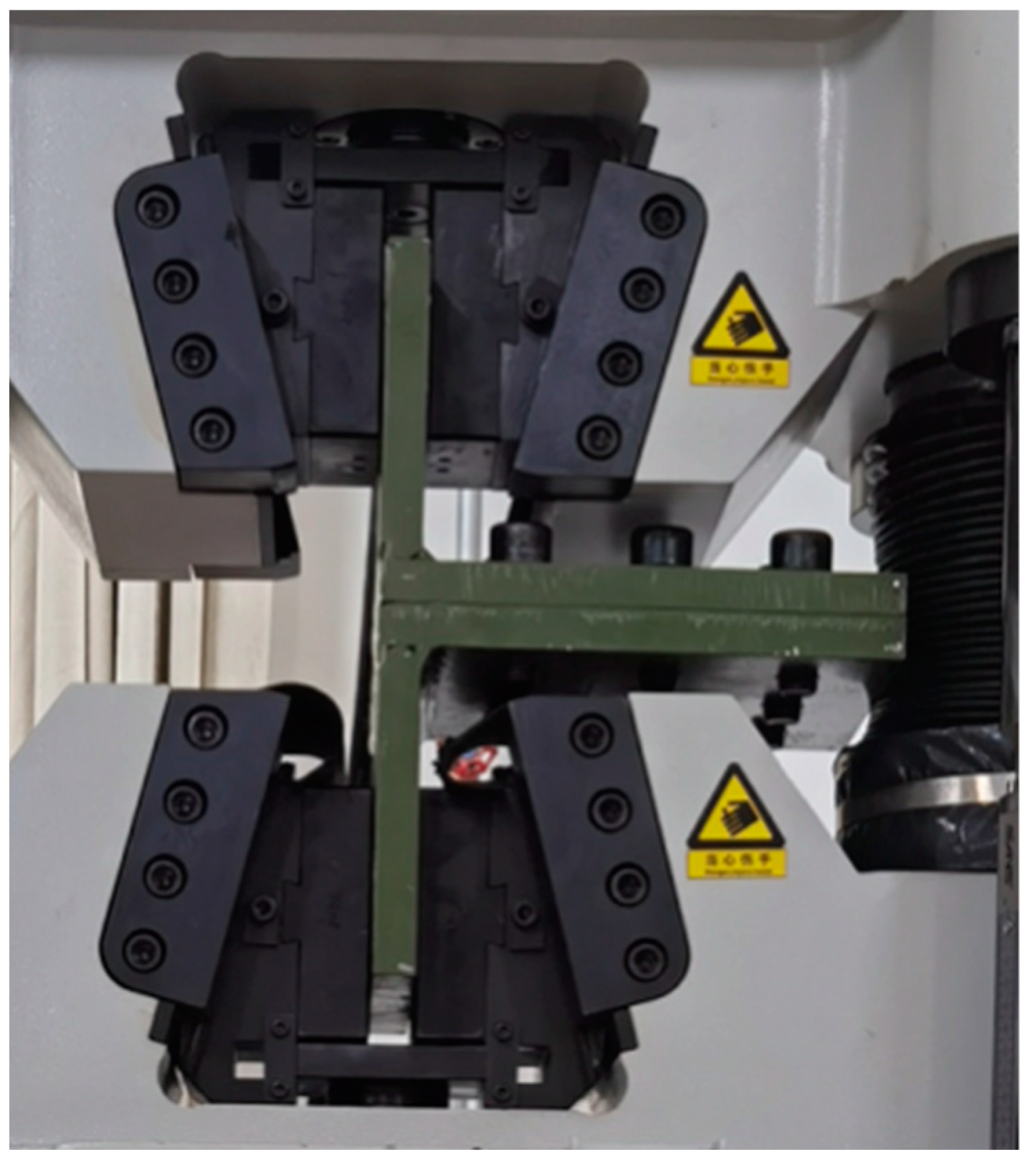
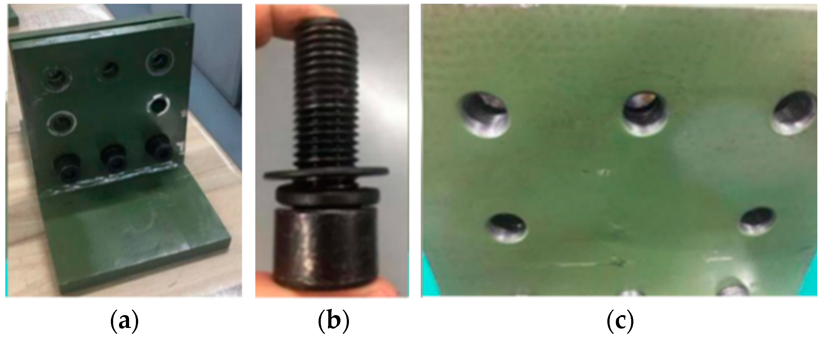
5.1. Specimen and Test Equipment
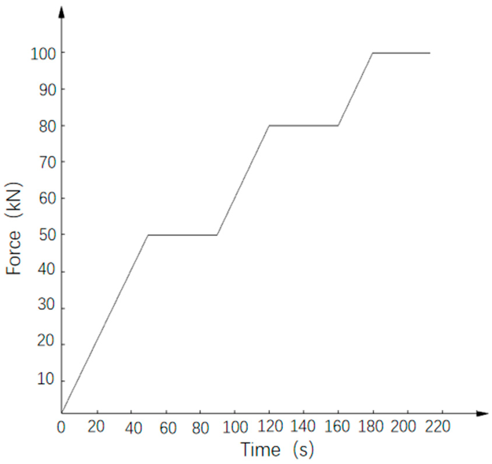
In order to align with the commonly used universal testing machine’s specification and size requirements and to closely replicate the structural geometry of the corner column and corner fitting joint, the bolt hole size, arrangement, and welding treatment form are kept consistent with the actual situation. The corner fitting and corner column are conservatively simplified into L-shaped specimens, as shown in Figure 10.
In order to analyze the fastening effect of bolts and internal threads on the end plate of the corner of the column seal plate, two groups of L-shaped specimens are prepared, namely through hole–threaded hole specimen and through hole–through hole specimen, as shown in Figure 11. The through hole–threaded hole specimen is fastened only by bolts, resembling the joint connection of the integrated modular house by flat pack. The through hole–through hole specimen adopts the bolt–nut connection mode to realize the joint fastening.
The tensile test of the bolted joint is carried out using the SHT4106 electric-hydraulic servo universal testing machine (maximum capacity of 1000 KN), as shown in Figure 12.
The L-shaped joint specimens are connected by eight M20 grade 8.8 hexagonal high-strength bolts and installed with a torque wrench to ensure that each bolt reaches the designed pre-tightening force. The assembled L-shaped specimen is placed on the test bench, and the position of the specimen is adjusted to ensure that the clamp is in the middle of the specimen, as shown in Figure 13. During the tests, the upper and lower L shapes are subjected to force and bending simultaneously, replicating actual working conditions.

5.2. Test Methods

The test of the joint connection of the integrated modular house by flat pack includes two types of loading tests. The relevant parameters of the test are shown in Table 4.
The through hole–thread hole specimen and the through hole–through hole specimen are first subjected to a graded loading test to analyze the reliability of the connection between corner fitting and corner column of the integrated modular house by flat pack. This test also assesses the allowable times of repeated disassembly and assembly and checks the fastening effect of the bolt–corner column internal thread hole connection mode.
The force control mode is adopted in the graded loading test. After a single test, the opening size of the L-shaped specimen is measured. The state of bolts, threaded holes, and through holes are evaluated, and the bolts are replaced. The next group of tests are repeated 10 times.
The variation in force with time in a single test is shown in Figure 14, with a loading rate of 1 kN/s. When the value of the force applied on the specimen reaches 50 kN, it is maintained for 40 s. Then, it continues to load up to 80 kN, remaining for 40 s. The loading then progresses to 100 kN and is held for 30 s before the test is stopped. Note that via calculation, the load on the corner fitting of the house does not exceed 100 kN.
In addition, destructive tests are carried out to analyze the maximum tensile force of the corner column–corner fitting joint and the deformation of the specimen in the failure process.
The curve of the loading process during the destructive test is shown in Figure 15. The displacement control method is adopted, and the test is stopped upon specimen yielding.

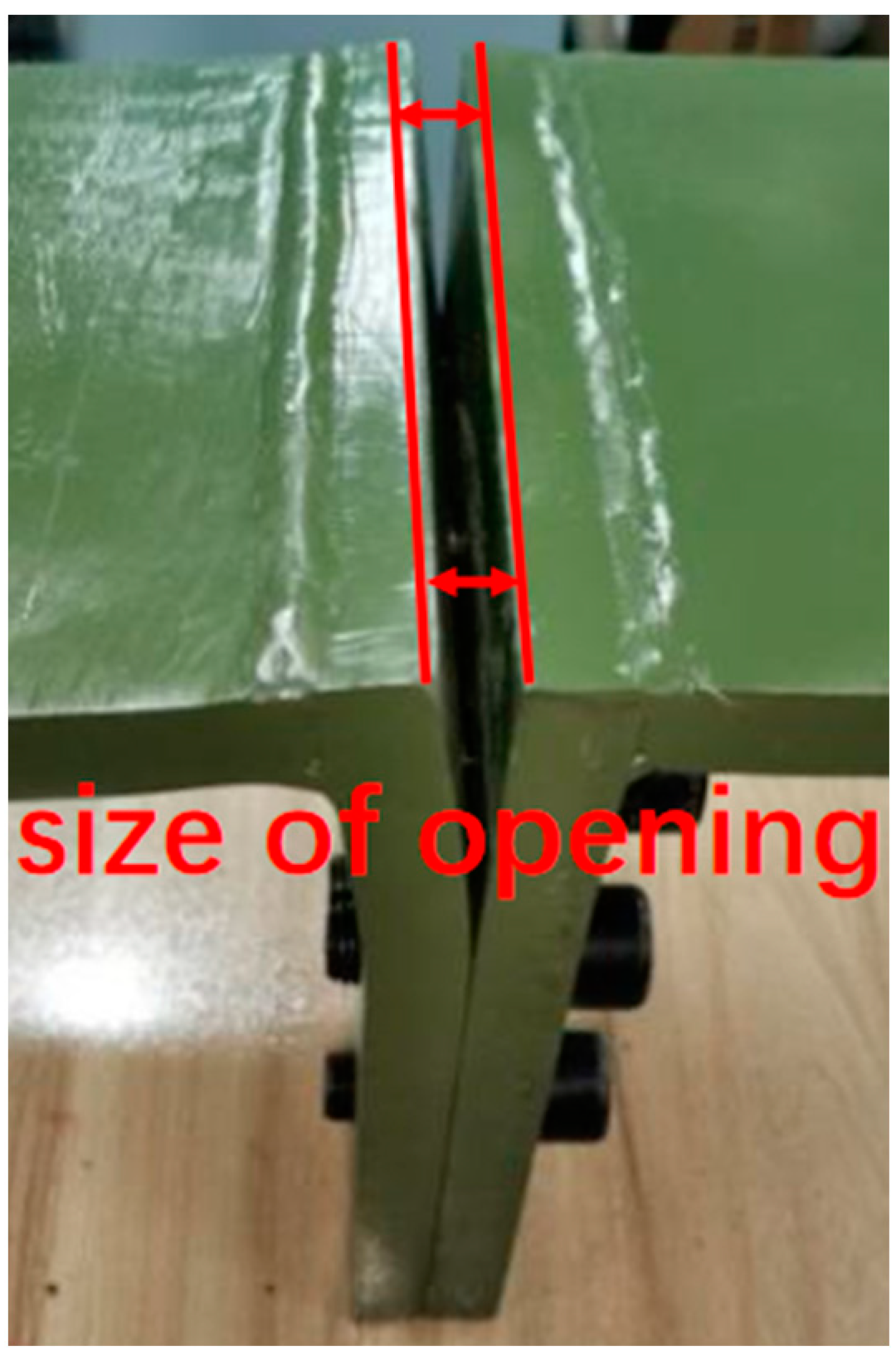
6. Result Analysis of Graded Loading Test

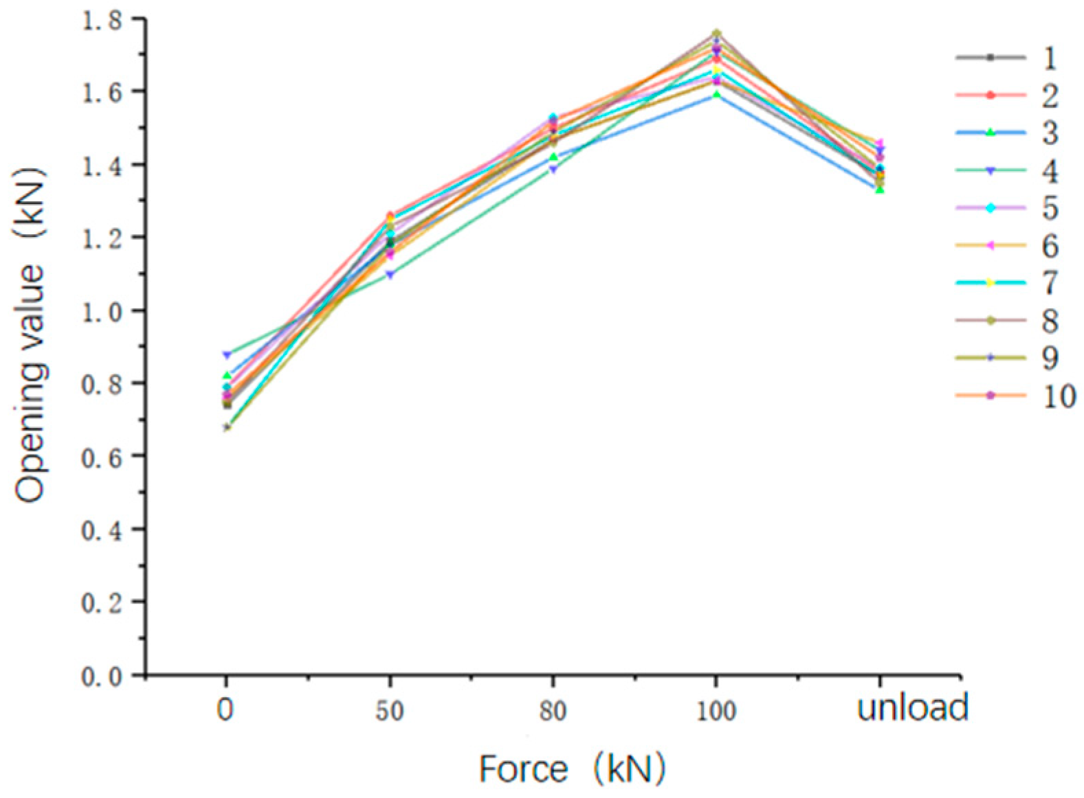
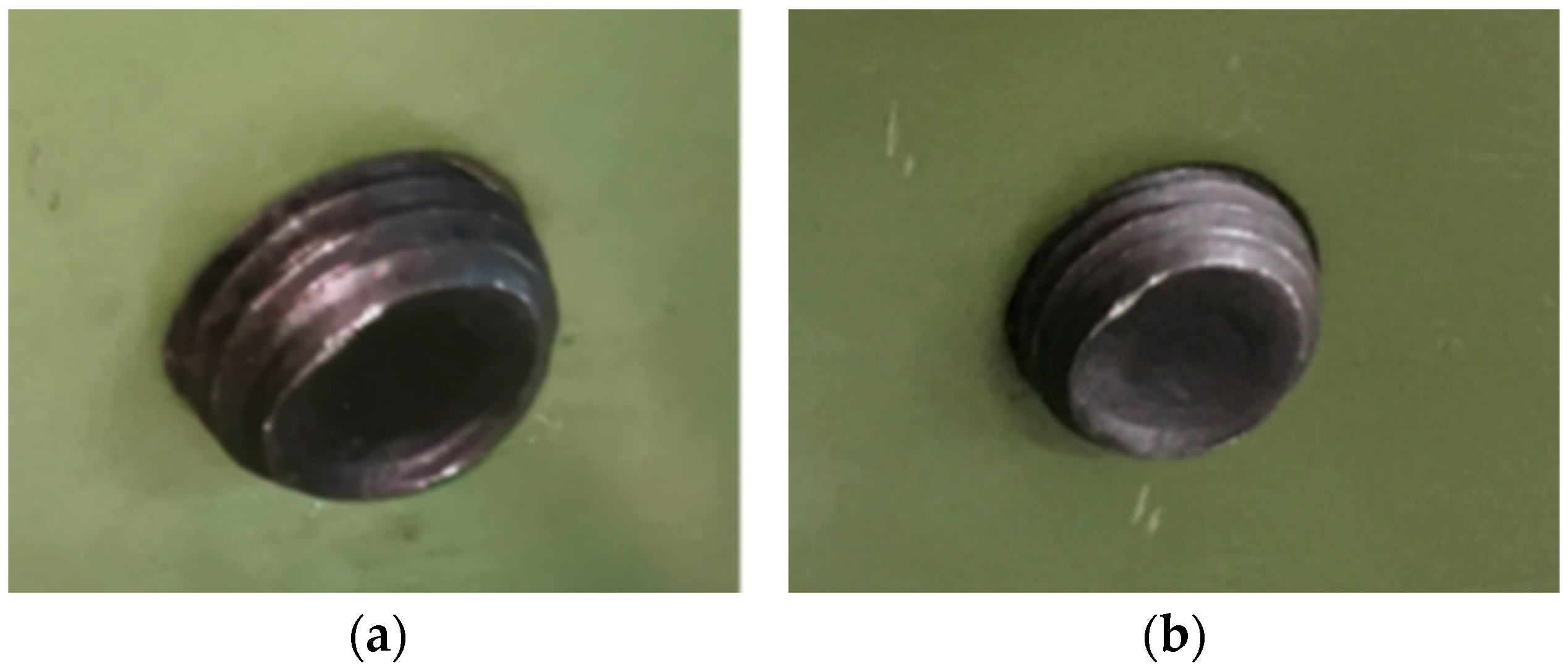
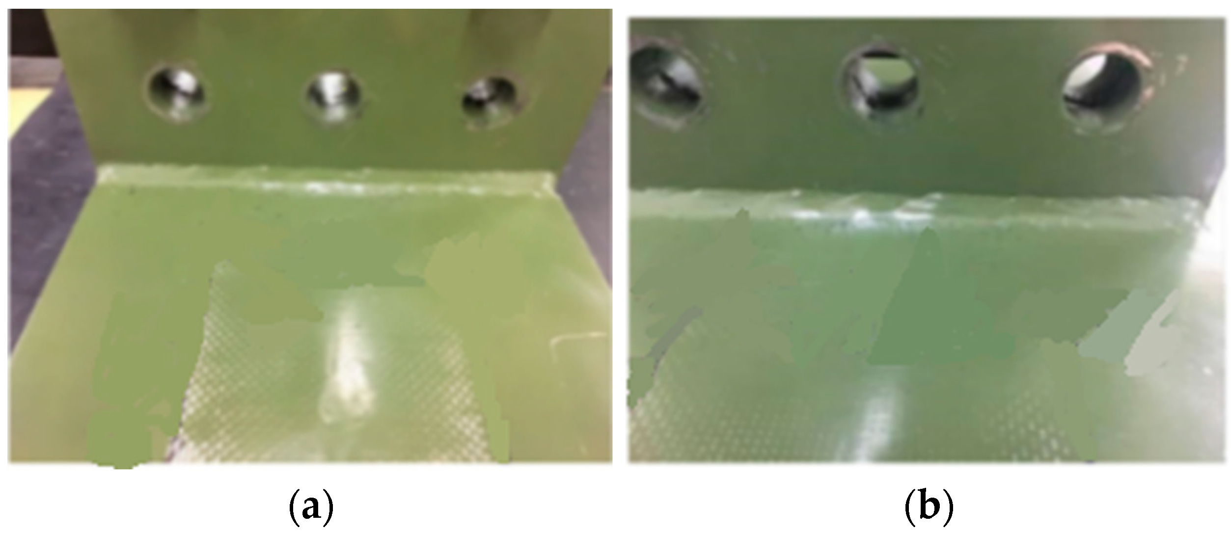
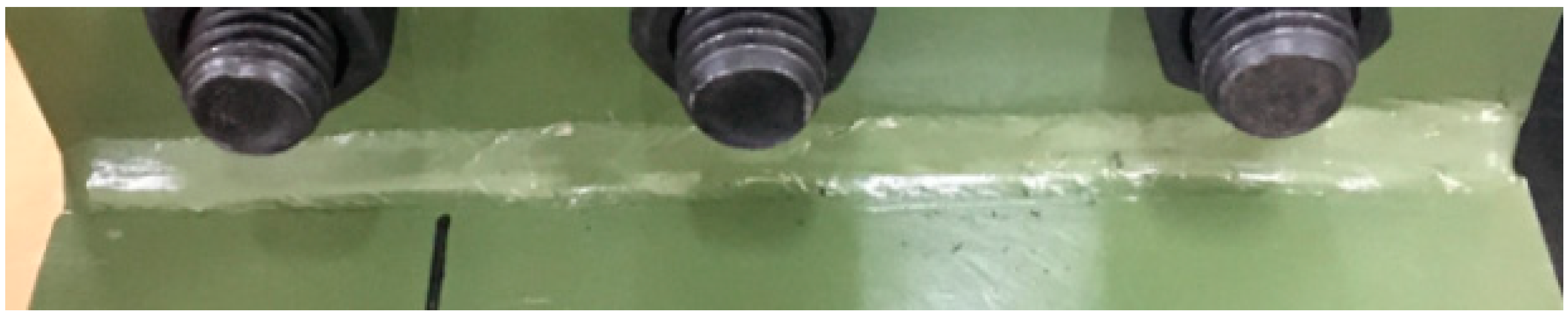
6.1. Results of Graded Loading Test of through Hole–Thread Hole Specimen

In the graded loading test of the through hole–threaded hole specimen, the variation in the force–displacement curve of the specimen is shown in Figure 16.
The curve is divided into two stages. The first stage spans force from 0 to 20 kN. In the process of clamping the specimen, there is a certain extent of relative displacement occurred between the two L-shaped specimens. Therefore, the displacement of the first stage varies greatly with the force. The second stage spans tensile force from 20 kN to 100 kN, with displacement increasing alongside force until the tests conclude at 100 kN, yielding an ultimate displacement of 4.4 mm.
In order to evaluate whether plastic deformation occurs in the process of graded loading, the opening size discrepancy measured during the loading and unloading process (the average size of the opening at the left and right ends of the specimen) is shown in Figure 17.
The change in the specimen opening during loading and unloading over 10 cycles is shown in Figure 18, and the average value of the opening in the graded loading test of the specimen is shown in Table 5. The opening value slightly increases with force but remains within 1.390 mm during the unloaded state.
The comparison of bolt threads before and after the test is shown in Figure 19. After unloading, the bolt protrudes part of the threads of the specimen half a circle less than that before loading. During disassembly, the three bolts near the weld position are easier to disassemble than the other bolts, indicating loosening and incomplete restoration after loading.
The threaded holes of the specimen before and after multiple loading steps are shown in Figure 20. The threaded hole near the weld position of the specimen shows clear texture and no cracks, with slight deformation under pretension but no damage after multiple loading steps.
The weld area of the specimen after multiple loading steps is shown in Figure 21. The specimen weld is intact and with no crack or plastic deformation, confirming the specimen’s potential for repeated normal use.

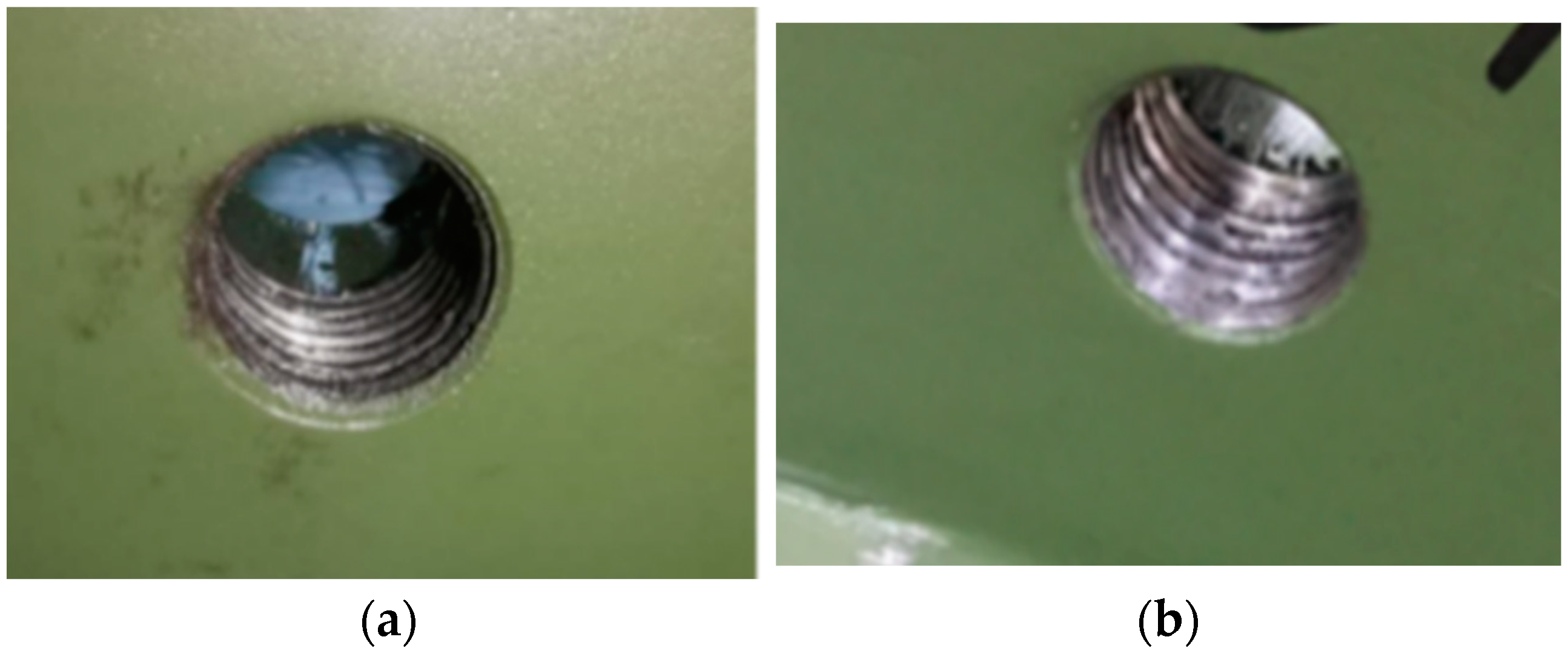
6.2. Test Results of Graded Loading of Through Hole–Through Hole Specimens

In the process of graded loading test of through hole–through hole specimen, the trend of force–displacement curve is essentially consistent with that of the through hole–thread hole specimen. The experiment concludes when the force of the specimen is loaded up to 100 kN, corresponding to a displacement of 4.7 mm.
Throughout the ten graded loading tests, the change in the opening size of the through hole specimen is shown in Figure 22, and the average value of specimen opening is shown in Table 6. As force increases, the openings at the right and left ends of the specimen linearly expand. Additionally, the opening of the specimen rebounded after unloading, indicating elastic deformation during the loading and unloading stages.
The comparison of bolts before and after the test is shown in Figure 23. After loading and unloading, part of the thread of the bolt protruding from the nut decreases by approximately one turn compared to its pre-loading stage. The three bolts near the weld position are more easily disassembled than those farther away, suggesting a kickback phenomenon during loading and unloading. Since the L-shaped specimens are all through holes, this kickback phenomenon does not hinder the specimen’s return to the unloaded state after unloading.
The state of the specimen after multiple graded loading steps is shown in Figure 24, revealing no deformation in the through hole specimen after loading.
The state of the weld seam of the specimen after multiple loading is shown in Figure 25.
In comparison with the through hole–through hole specimen, the through hole–threaded hole specimen cannot be completely restored to its initial state due to the existence of the bolt kickback phenomenon during loading. However, it does not affect normal use and meets the time requirement for repeated disassembly and assembly.

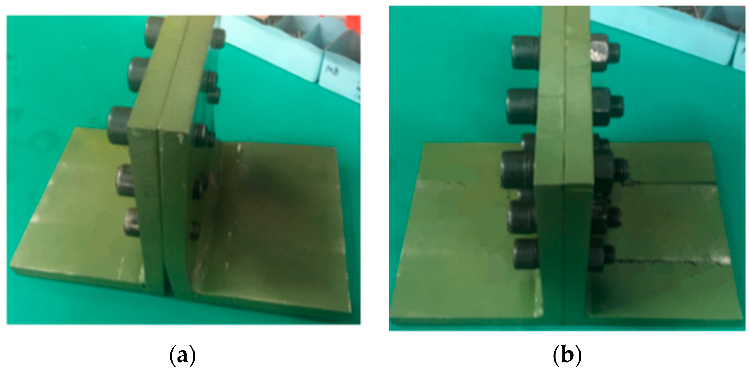
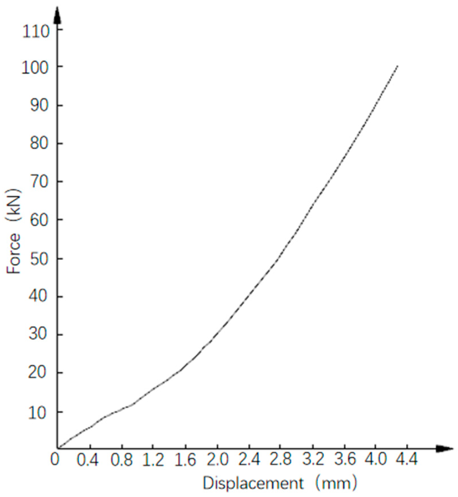
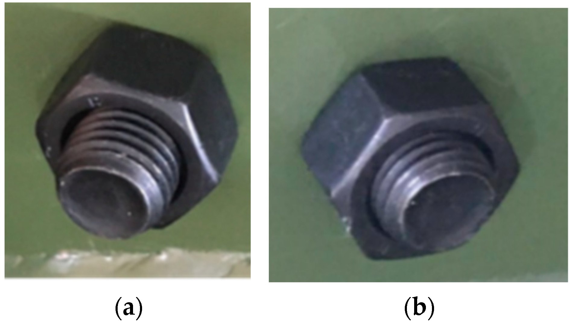
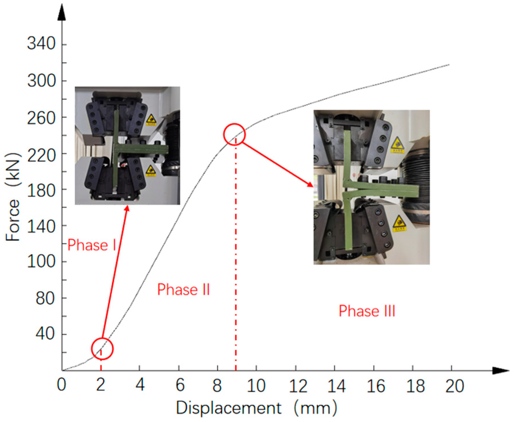
7. Results Analysis of Destructive Test

During the destructive test, the curve of displacement and force of the specimen is shown in Figure 26. The force–displacement curve is divided into three stages. In the first stage, the displacement increases rapidly with the increase in force. To apply force, the clamp needs to overcome the assembly clearance and undergo elastic deformation while clamping the specimen.
In the second stage, the entire specimen experiences elastic deformation until the force reaches 249 kN, resulting in a maximum displacement of 9 mm. The force–displacement curve is relatively smooth, with a consistent slope and no inflection point. The third stage is the plastic deformation. When the force reaches 300 kN, the relative displacement of the L-shaped specimen reaches 16 mm. After unloading, the relative displacement decreases to 11.68 mm.
After the test, the five bolts of the specimen located far from the weld position can be removed normally, and the removed bolts and the threaded holes of the specimen are shown in Figure 27. The bolts show no deformation, and the threaded holes show slight deformation. The plastic deformation of the specimen near the weld is severe, where the three bolts are bent, and the thread pairs are damaged, preventing normal removal.
The weld of the specimen after unloading is shown in Figure 28. Although the specimen has plastic deformation, there are no cracks or deformations in the weld region. Therefore, the weld strength ensures the connection stability and safety of the specimen under large force.

8. Conclusions

In this study, integral finite element models of an integrated modular house by flat pack with the elastic–plastic contact relationship in the corner fitting are established. The overall displacement and equivalent stress distribution of the house under different loading conditions are analyzed. A simulated tensile loading test on the corner column-corner fitting joint is carried out to analyze the opening state of the specimen after the test. The following conclusions are drawn:
(1)
The finite element model of connection joints, based on elastic–plastic contact theory, addresses the problem of oversimplification in traditional rigid or semi-rigid connection methods. It clearly and intuitively shows the deformation of the contact surface between the corner and the main beam, along with the law of equivalent stress distribution. Combined with the tensile test, the stiffness and strength of the corner fitting could be evaluated comprehensively, and the analysis results are deemed reliable.
(2)
Under the load conditions listed in this paper, the maximum displacement of the integrated modular house by flat pack is 6.813 mm, and the maximum equivalent stress is 223.0 MPa, which is less than the allowable stress of the material. The whole structure meets the requirements of the relevant design codes.
(3)
When the end plate connection holes of the corner column seal are designed by through holes and internal screw holes, respectively, the fastening effect of bolting between the corner fitting and corner column using the internal screw hole is superior.
(4)
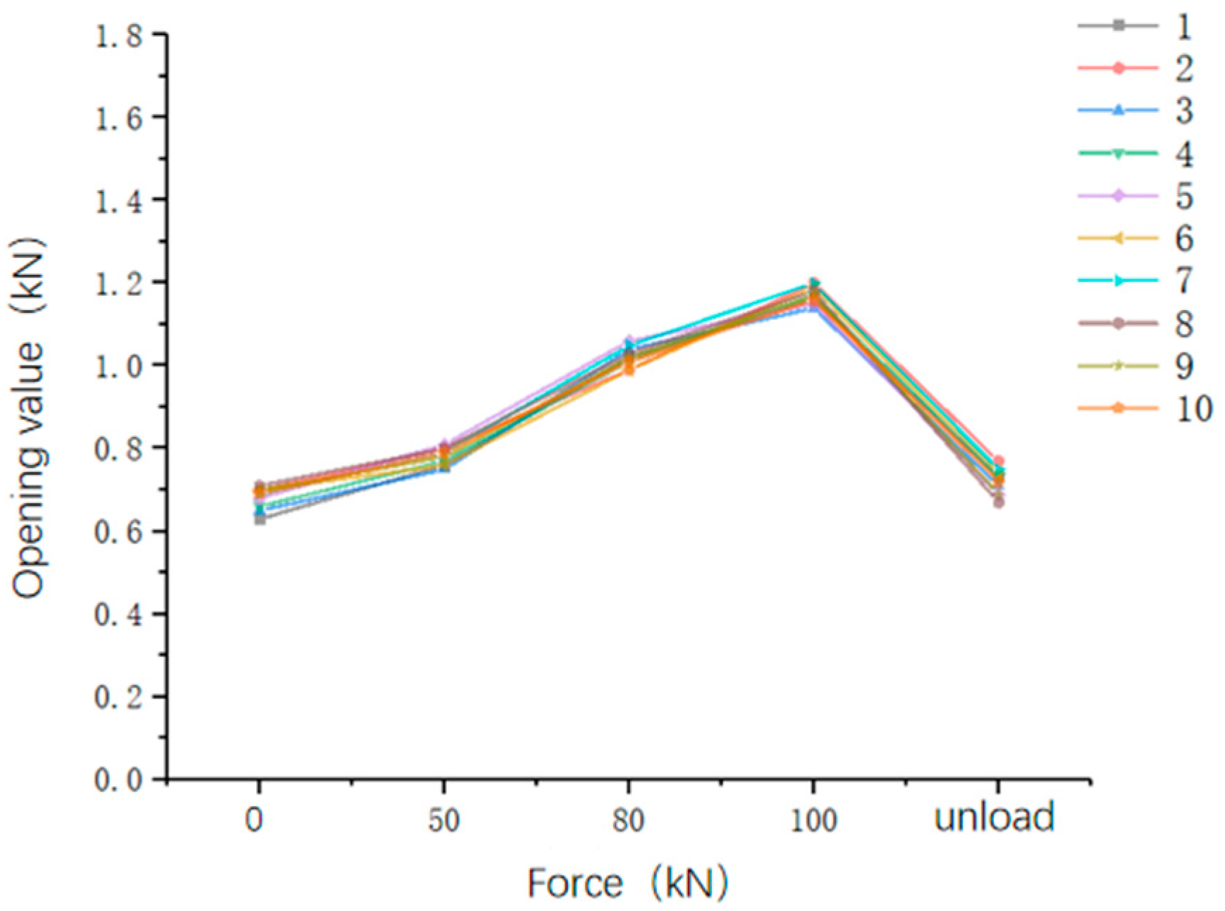
In the simulated cycle test of fastening and unloading the specimen, all bolts and threads could be used normally after ten repeated loading and unloading cycles, which demonstrates the continuous fault-free use of corner column-corner fitting joint connections. It also illustrates the reliability of the disassembly and use capability of the key connection joints of the house.

Author Contributions

Conceptualization, A.Z., L.Z. and Y.M.; methodology, A.Z., L.Z. and J.Z.; software, L.Z., Y.M. and R.Y.; validation, A.Z., L.Z., Y.M. and H.M.; formal analysis, S.C. and X.W.; investigation, A.Z., L.Z., Y.M. and J.Z.; resources, A.Z. and J.Z.; data curation, Y.M. and S.C.; writing—original draft preparation, L.Z., Y.M., X.W. and H.M.; writing—review and editing, A.Z., S.C. and J.Z.; visualization, H.M. and R.Y.; supervision, A.Z., L.Z. and J.Z.; project administration, A.Z. and L.Z.; funding acquisition, A.Z. All authors have read and agreed to the published version of the manuscript.

Funding

This research received no external funding.

Institutional Review Board Statement

Not applicable.

Informed Consent Statement

Not applicable.

Data Availability Statement

Data are contained within the article.

Conflicts of Interest

The authors declare no conflicts of interest.

References

  1. Tang, R.B. Research on Development and Technical System of Steel Structure Assembly Building. J. Real Estate World 2021, 20, 137–139. [Google Scholar]
  2. Liu, H.J.; Zhu, Y.X.; Wang, Q. New Strategy under the Current Development of Prefabricated Residential Buildings. J. Sichuan Archit. 2021, 41 (Suppl. S1), 22–24. [Google Scholar]
  3. Mei, J.H. Developing Steel Structure Assembly Building. J. China Eng. Consult. 2018, 4, 67. [Google Scholar]
  4. Xu, J.C.; Cai, J.W.; Cai, J.Z. Research on a new type of temporary building-environmentally friendly folding house. J. China Stand. 2019, 540, 28–29. [Google Scholar]
  5. Yi, J.; Park, J.H.; Park, W.; Choo, J.F. Design and Cost-Effectiveness of 5-Tier Foldable Container. Arab. J. Sci. Eng. 2022, 47, 12839–12852. [Google Scholar] [CrossRef]
  6. Giriunas, K.; Sezen, H.; Dupaix, R. Evaluation, modeling, and analysis of shipping container building structures. J. Eng. Struct. 2012, 43, 48–57. [Google Scholar] [CrossRef]
  7. Wei, Q.C. Realization of a new type of solar foldable emergency relief house. J. Green Sci. Technol. 2018, 3, 145–147. [Google Scholar]
  8. Sun, Y.; Wang, J.; Wu, J.; Shi, W.; Ji, D.; Wang, X.; Zhao, X. Constraints Hindering the Development of High-Rise Modular Buildings. J. Appl. Sci. 2020, 10, 7159. [Google Scholar] [CrossRef]
  9. Dai, M.M. In-Situ Experimental Study on Overall Lateral Resistance of Assembled Cold-Formed Thin-Walled Light Steel Movable Plate House. Master’s Thesis, Kunming University of Science and Technology, Kunming, China, 2017. [Google Scholar]
  10. Tominaga, Y.; Akabayashi, S.-I.; Kitahara, T.; Arinami, Y. Air flow around isolated gable-roof buildings with different roof pitches: Wind tunnel experiments and CFD simulations. J. Build. Environ. 2015, 84, 204–221. [Google Scholar] [CrossRef]
  11. Liu, Y.; Chen, Z.H.; Liu, J.D.; Zhong, X.; Liu, X.W.; Jiang, J.C. Effects of various reinforcing intra-module connection details on seismic behavior of corner-supported steel modular buildings. Structures 2022, 40, 555–570. [Google Scholar] [CrossRef]
  12. Ma, S.C.; Gu, Y.; Bao, P. Analysis and evaluation on seismic performance of the composite wallboard joints integrating thermal insulation and load bearing. J. Build. Eng. 2023, 76, 107259. [Google Scholar] [CrossRef]
  13. Ma, S.C.; Hou, D.F.; Bao, P.; Wano, D.T. Influence of alkali-resistant glass fiber on seismicperformance of precast ceramsite concrete sandwich wall panels. Structures 2022, 38, 94–107. [Google Scholar] [CrossRef]
  14. Ma, S.C.; Lou, Y.Y.; Bao, P. Experimental study of bending resistance of pre-fabricated truss beams under eccentric loads. J. Build. Eng. 2022, 49, 104119. [Google Scholar] [CrossRef]
  15. Li, S. Study on Dynamic Characteristics and Vibration Comfort Analysis of Light Steel Movable Plate House. Master’s Thesis, Kunming University of Science and Technology, Kunming, China, 2021. [Google Scholar]
  16. Lin, H.H.; Cheng, J.H. A Study of the Simulation and Analysis of the Flow Field of Natural Convection for a Container House. J. Sustain. 2020, 12, 9845. [Google Scholar] [CrossRef]
  17. Fan, K.J.; Zha, X.X. Analysis of lateral stiffness of container house Ⅱ: Influence of side plate opening. J. Harbin Inst. Technol. 2017, 49, 109–116. [Google Scholar]
  18. Wang, Y.; Li, J.F. The analysis of internal force of semi-rigid steel frame. J. Mech. Eng. 2003, 2, 35–38. [Google Scholar]
  19. Wang, Y.Q.; Zhang, Y.Z.; Shi, G.; Shi, Y.J.; Shu, X.P. Elastic Time-history Analysis of Multi-story Steel Frame with Semi-rigid End-plate Conections in Earthquake Response. Earthq. Resist. Eng. Retrofit. 2007, 2, 28–32. [Google Scholar]
  20. Yang, S.S.; Wang, Y. Research on the moment capacity of fully assembled column-beam joint composed of outer sleeve and strengthed exthended end-plate. J. Ind. Constr. 2017, 47, 7–166. [Google Scholar]
  21. Yang, S.S.; Wang, Y.; Ma, Q.Q. Experimental study on seismic behavior of prefabricated outer sleeve-overhang plate joint between column and beam. J. China Civ. Eng. J. 2017, 50, 76–86. [Google Scholar]
  22. Zhang, J.F.; Yang, D.Y.; Hu, W.T. Research on overall flexural stiffness of assembled box house. J. Steel Constr. 2016, 31, 28–32. [Google Scholar]
  23. Zhao, B.D. Extended End-Plate Bolted Connections Performance Study of Steel Frame Structure; Xi’an University of Architecture and Technology: Xi’an, China, 2006. [Google Scholar]
  24. Yang, X.J.; Zhang, L.; Li, G.Q.; Liu, Y.S.; Lu, Y.; Sun, J.Y. Hysteretic Performance of End Plate Connections between Rectangular Hollow Section Columns and H-Shaped Beams Using Through-Bolts. J. Prog. Steel Build. Struct. 2013, 15, 16–23. [Google Scholar]
  25. Liu, W.; Tan, P.; Hao, L.F.; Zhou, F.L. Calculation of basic natural period of vibration of semi-rigid connection steel frame with sides way. J. Steel Constr. 2018, 33, 6–10+91. [Google Scholar]
  26. Su, J.L.; Li, X.M.; Qi, R. Second-Order Elastic Stability Analysis of Steel Semi-Rigid Frame. J. Build. Sci. 2011, 27, 15–19. [Google Scholar]
  27. Feng, J.B. Second-Order Analysis Design Method for Flush End-Plate Semi-Rigid Connection Steel Frames. Master’s Thesis, Zhengzhou University, Zhengzhou, China, 2016. [Google Scholar]
  28. Hu, X.B.; Shen, P.X.; Shu, X.P. Elastic time-history analysis of steel frame structures with semi-rigid connections. J. Earthq. Eng. Eng. Dyn. 2008, 28, 65–70. [Google Scholar]
  29. Wang, L.; Zhou, N.N.; Wang, G.B. Experimental research on seismic behavior of steel frame with top and seat angle with double web angles semi-rigid connections. J. Build. Struct. 2009, 39, 54–58. [Google Scholar]
  30. Wu, Y.; Peng, S.M.; Zhang, Q.L. Experimental and Numerical Studies on Seismic Behaviors of Steel Frames with Top-Seat and Double Web Angel Connections. J. Tongji Univ. 2005, 33, 1438–1442. [Google Scholar]
  31. Sun, L.; Li, F.X. Experimental study on seismic behavior of steel frame models with semi-rigid connections. J. World Earthq. Eng. 2005, 4, 143–147. [Google Scholar]
  32. Li, G.Q.; Wang, J.F.; Liu, Q.P. An experimental study of full-scale semi-rigid composite frames under vertical loading. China Civ. Eng. J. 2006, 7, 43–51+62. Available online: https://www.cnki.net/KCMS/detail/detail.aspx?dbcode=CJFD&dbname=CJFD2006&filename=TMGC200607007&uniplatform=OVERSEA&v=2z3_cOxsIlxMWlY7zhpt-h1sGtbNh7TJyZpbtT8UaXJJIsxYANTw2DltNQ__RXsO (accessed on 20 November 2023).
  33. Li, G.Q.; Liu, Q.P.; Wang, J.F. An experimental study of a full-scale semi-rigid composite frame under lateral loading. China Civ. Eng. J. 2007, 40, 8–16. Available online: https://www.cnki.net/KCMS/detail/detail.aspx?dbcode=CJFD&dbname=CJFD2007&filename=TMGC200712007&uniplatform=OVERSEA&v=euFq3z_dA5KdWz36mCJa2j17kUxX9of9VwqVqaie7wxw-ctPtpZSTXbVRIGWteOT (accessed on 20 November 2023).
  34. Zhang, J.F.; Yang, D.Y.; Guo, Q. Experimental research on the vertical bearing capacity of the removable box house. J. Ind. Constr. 2017, 47, 162–167. [Google Scholar]
  35. Zhang, J.F.; Yang, D.Y.; Hu, W.T. Experimental study on mechanical behavior of the bottom frame structure of removable box house. J. Build. Struct. 2017, 47, 22–27. [Google Scholar]
  36. Zhang, J.; Wu, C.H. Elasto-plastic analysis of wheel-rail contact problem. J. China Railw. Soc. 2000, 3, 16–21. [Google Scholar]
  37. Rajendr Prasad, R.; Chidambaram, K.R. Cost Analysis of Foldable Containers on Container Freight Station and Port in Chennai Region. Eng. Appl. Sci. 2017, 12, 6764–6768. [Google Scholar]
  38. Zhang, G.P.; Ma, C. The Key Issue Exploration in Modular Design of Prefabricated Houses. J. Jilin Jianzhu Univ. 2016, 33, 57–60. [Google Scholar]
  39. Yang, Y.P.; Huang, Y.S.; Zeng, F.L.; Zhang, H.S. Static Elastoplastic Analysis of Concrete-filled Steel Tube Gravity Column-concrete Core Tube Structure. South China J. Seismol. 2021, 41, 157–163. [Google Scholar]
  40. Refachinho, D.; Neto, A.G. Rigid body formulation in a finite element context with contact interaction. Comput. Mech. 2018, 62, 1369–1398. [Google Scholar] [CrossRef]
  41. GB/50009-2012; Load Code for the Design of Building Structures. China Construction Industry Press: Beijing, China, 2012.
  42. GB/T 228.1-2021; Metallic Materials—Tensile Testing—Part 1: Method of Test at Room Temperature. China Standard Publishing House: Beijing, China, 2021.
Figure 1. Integrated modular house by flat pack: (a) single unit; (b) transportation; (c) assembly; (d) combination; (e) connection joint.
Buildings 14 00635 g001
Figure 2. Contact pair.
Buildings 14 00635 g002
Figure 3. Schematic of integrated modular house by flat pack.
Buildings 14 00635 g003
Figure 4. Bolt hole arrangement at corner (unit: mm): (a) side view; (b) top view; (c) bottom view.
Buildings 14 00635 g004
Figure 5. Schematic diagram of beam–column joints: (a) overall view; (b) section view.
Buildings 14 00635 g005
Figure 6. Model of integrated modular house by flat pack: (a) finite element meshes; (b) constraints and loads.
Buildings 14 00635 g006
Figure 7. Diagram of wind loads.
Buildings 14 00635 g007
Figure 8. The overall equivalent stress cloud chart of the house under the action of working condition 1.
Buildings 14 00635 g008
Figure 9. Elastic–plastic contact equivalent stress cloud chart of corner fitting and corner column under the action of working condition 2: (a) upper corner fitting; (b) upper surface of corner column; (c) lower corner fitting; (d) lower surface of corner column.
Buildings 14 00635 g009
Figure 10. L-shaped joint specimen.
Buildings 14 00635 g010
Figure 11. Specimen: (a) through hole–thread hole specimen; (b) through hole–through hole specimen.
Buildings 14 00635 g011
Figure 12. SHT4106 electric-hydraulic servo universal testing machine.
Buildings 14 00635 g012
Figure 13. The installation state of specimen in the test bench.
Buildings 14 00635 g013
Figure 14. Loading mode of graded loading test.
Buildings 14 00635 g014
Figure 15. Loading curve of destructive test.
Buildings 14 00635 g015
Figure 16. Force–displacement curve of through hole–threaded hole specimen.
Buildings 14 00635 g016
Figure 17. Schematic diagram of specimen opening.
Buildings 14 00635 g017
Figure 18. Opening sizes of through hole–threaded hole specimen.
Buildings 14 00635 g018
Figure 19. Bolt thread state before and after loading of through hole–threaded hole specimen: (a) before loading; (b) after loading.
Buildings 14 00635 g019
Figure 20. Thread state of through hole–thread hole specimen before and after loading: (a) before loading; (b) after loading.
Buildings 14 00635 g020
Figure 21. Weld state of through hole–threaded hole specimens after repeated loading.
Buildings 14 00635 g021
Figure 22. Opening size of through hole specimen.
Buildings 14 00635 g022
Figure 23. Through hole–through hole specimen bolt thread state: (a) before loading; (b) after loading.
Buildings 14 00635 g023
Figure 24. State of specimen after multiple graded loading steps: (a) after the second loading; (b) after the fourth loading.
Buildings 14 00635 g024
Figure 25. The weld seam is intact without any damage.
Buildings 14 00635 g025
Figure 26. Force–displacement curve of specimen in the destructive test.
Buildings 14 00635 g026
Figure 27. Bolt and specimen after disassembly: (a) specimen; (b) bolt; (c) threaded hole.
Buildings 14 00635 g027
Figure 28. Weld state after unloading in the destructive test.
Buildings 14 00635 g028
Table 1. Conditions of load combination.
Loading ConditionsDesign Loads
Condition 11.3 × dead load + 1.5 × live load
Condition 21.3 × dead load + 1.5 × live load + 1.5 × 0.6 × wind load
Condition 31.0 × dead load + 1.0 × live load
Condition 41.0 × dead load + 1.0 × live load + 0.6 × wind load
Note: the loads involved in Table 1 are characteristic values.
Table 2. Comparison of the maximum deformation of the house in three directions.
Loading Conditionsx-Direction (mm)y-Direction (mm)z-Direction (mm)
Condition 10.1446−3.070−0.3919
Condition 26.813−2.318−0.4818
Condition 30.1078−2.159−0.2754
Condition 43.720−1.663−0.2806
Table 3. Comparison of the maximum equivalent stress of buildings.
Loading ConditionsEquivalent Stress (MPa)
Condition 1215.6
Condition 2223.0
Condition 3204.1
Condition 4210.7
Table 4. Test methods.
Test ParametersDestructive TestGraded Loading Test
Test standardGB/T 228.1-2021GB/T 228.1-2021 [42]
Specimen width (b)/mm2020
Specimen length (L)/mm220220
Cross-sectional area (So)/mm244004400
Control modeDisplacement controlForce control
Control speed20 mm/min1000 N/s
Bolt preload force/N∙m6060
Load force value/kNNo upper limit50/80/100
Force holding time/s/30
Table 5. Average values of through hole–threaded hole specimen openings for graded loading tests.
Tensile Value/kNOpening Average Value/mm
Not loaded0.766
501.191
801.473
1001.677
Unload1.390
Table 6. Average opening of through hole–through hole specimen in graded loading test.
Tensile Value/kNOpening Mean Value/mm
Before load0.681
500.781
801.022
1001.172
Unload0.720
Disclaimer/Publisher’s Note: The statements, opinions and data contained in all publications are solely those of the individual author(s) and contributor(s) and not of MDPI and/or the editor(s). MDPI and/or the editor(s) disclaim responsibility for any injury to people or property resulting from any ideas, methods, instructions or products referred to in the content.

