

Improvement of Mechanical Properties of Compressed Earth Blocks with Stabilising Additives for Self-Build of Sustainable Housing

 , , ,
, , ,
Abstract
:1. Introduction
2. Materials and Methods
2.1. Earth Materials
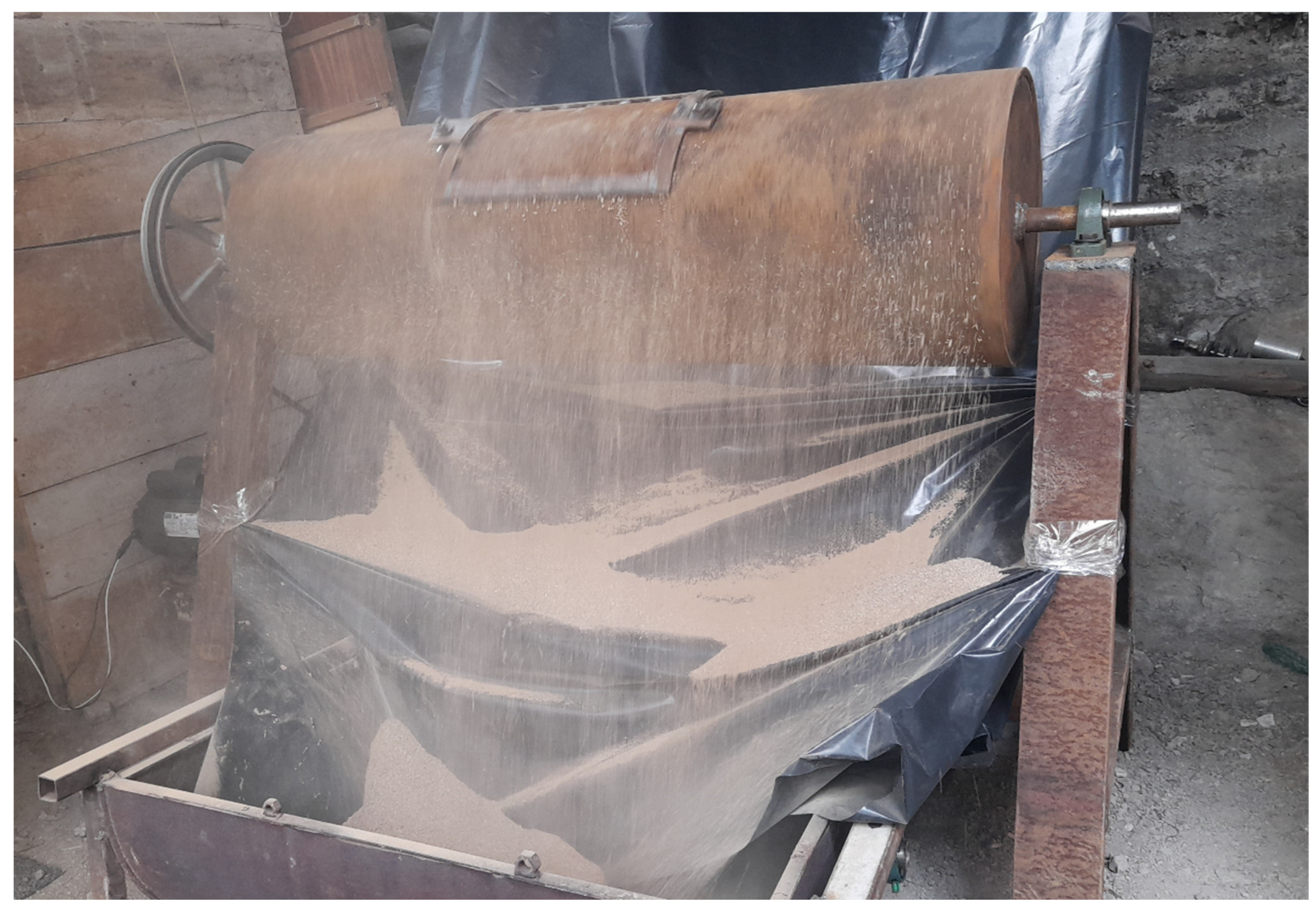
2.2. Earth Characterisation
- The odour test allows for the identification of organic matter or humus.
- The bite test allows for the differentiation of the predominance of clay in the stickiest samples.
- The washing test identifies whether the sample is sandy, silty or clayey, depending on the need to use less or more water to remove debris and dirt.
- The cut test consists of cutting the sample and determining whether clay is predominant when seen as shiny or silts if the cut is opaque.
- The ball test consists of dropping a ball on a flat surface and determining its composition so that the sample contains more clay if it does not flatten and crack and less if it breaks up.
- The consistency test requires moulding the sample into an earthworm shape, thus identifying the appropriate moisture content to form a 3 mm earthworm shape. This sample is then shaped into a ball to be dried for 48 h. If the ball is easy to break, it will have a low clay content, whereas if it is more consistent, it will have a higher clay content. If it is not possible to form the ball, it is identified as a sandy sample.
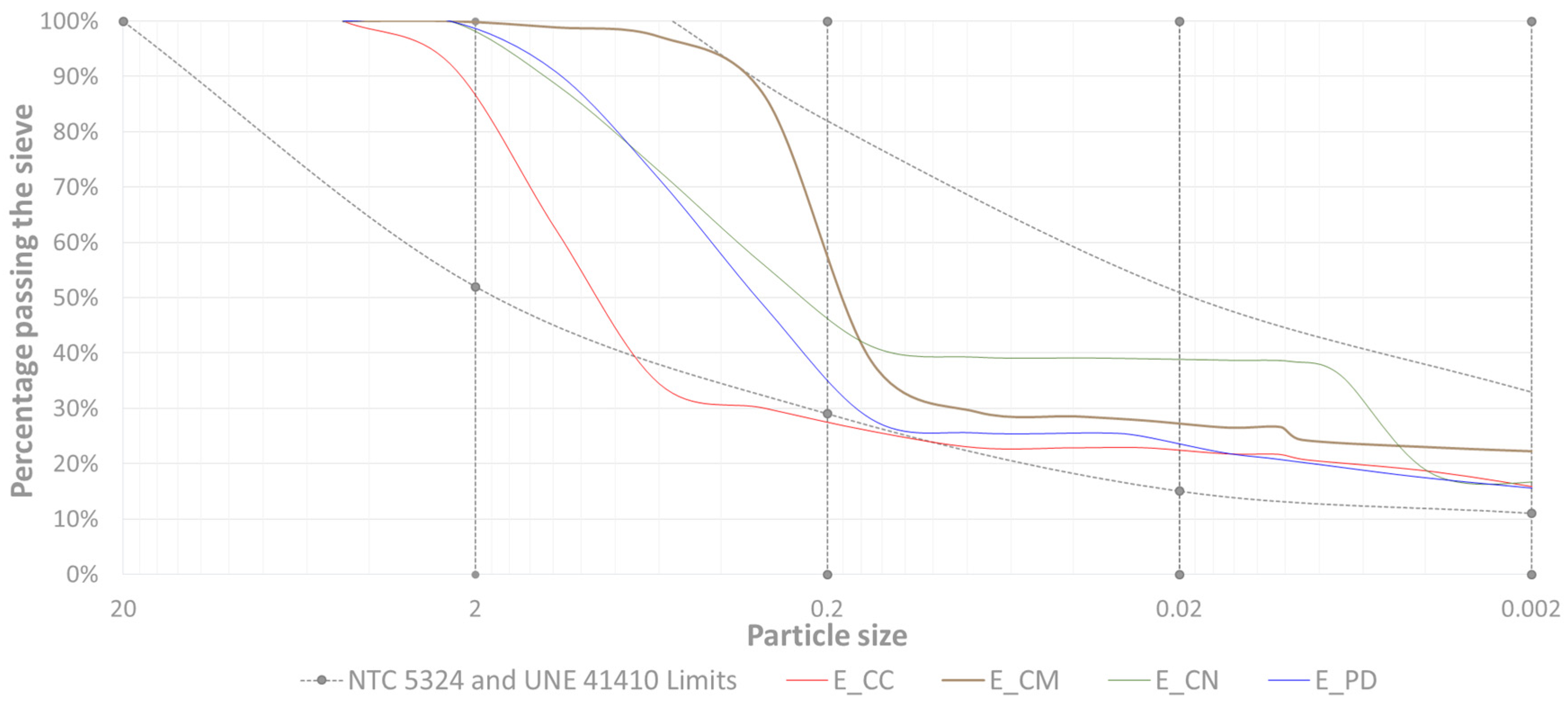
- Granulometric analysis allows the earth to be classified into gravel, sand, silt and clay according to the particle size that passes through each of the sieves [37].
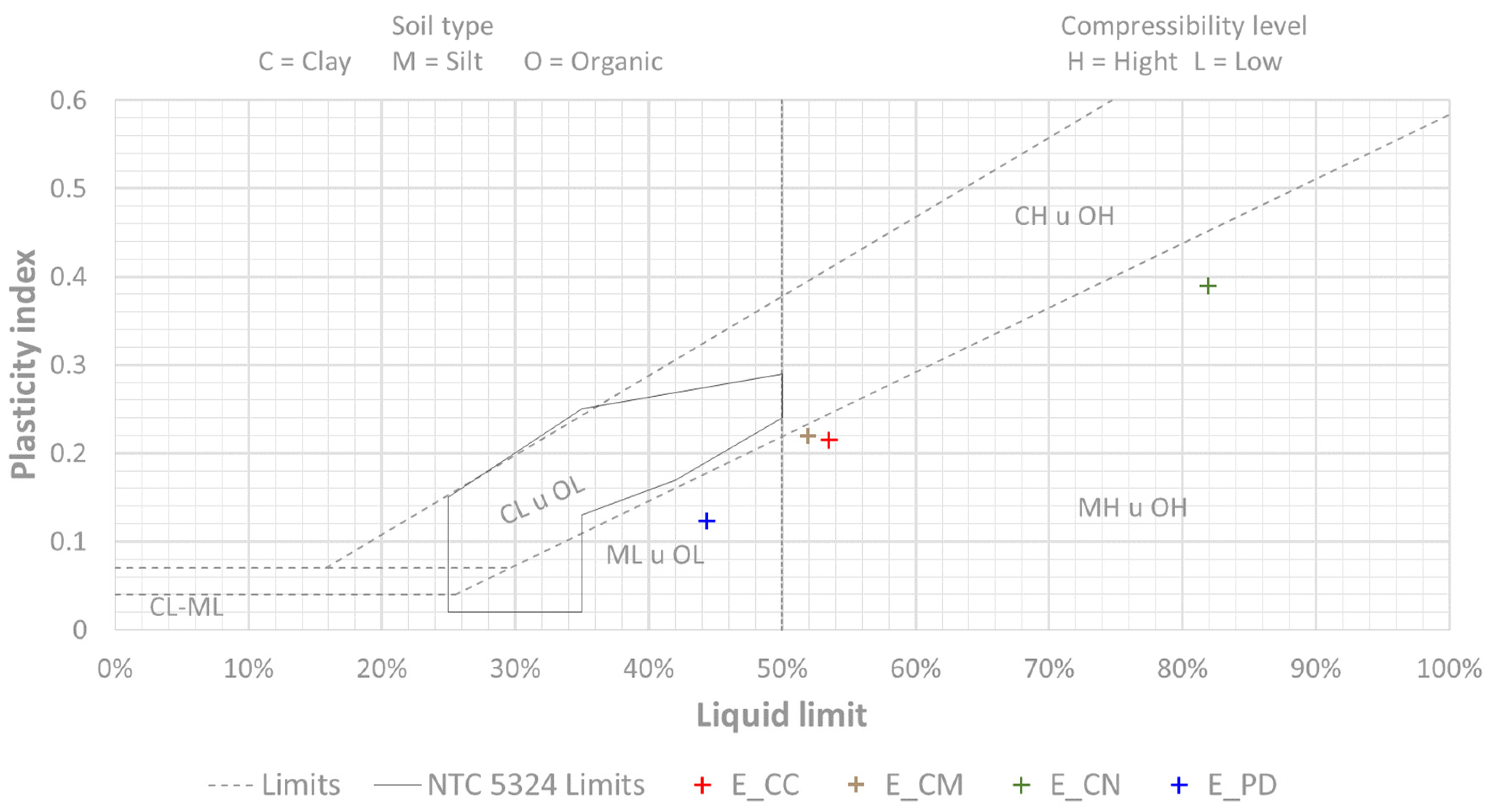
- The plasticity test allows us to know the plastic limit. Thanks to this test, it is also possible to obtain properties such as the plasticity index, tenacity, liquidity and consistency [38].
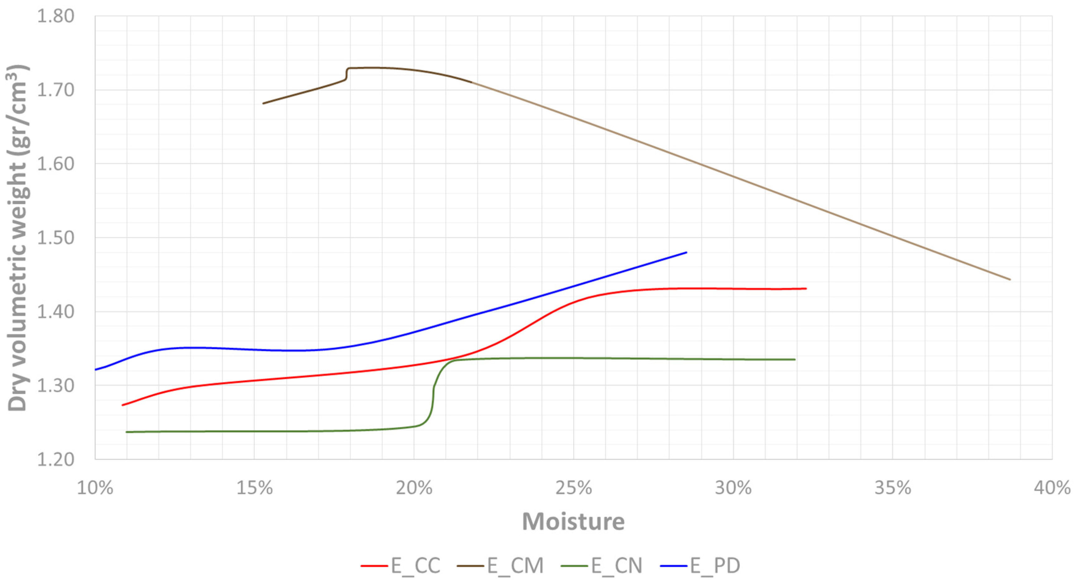
- The compaction test or the standard Proctor test allows for the determination of the moisture–density ratio of the compacted material [39].
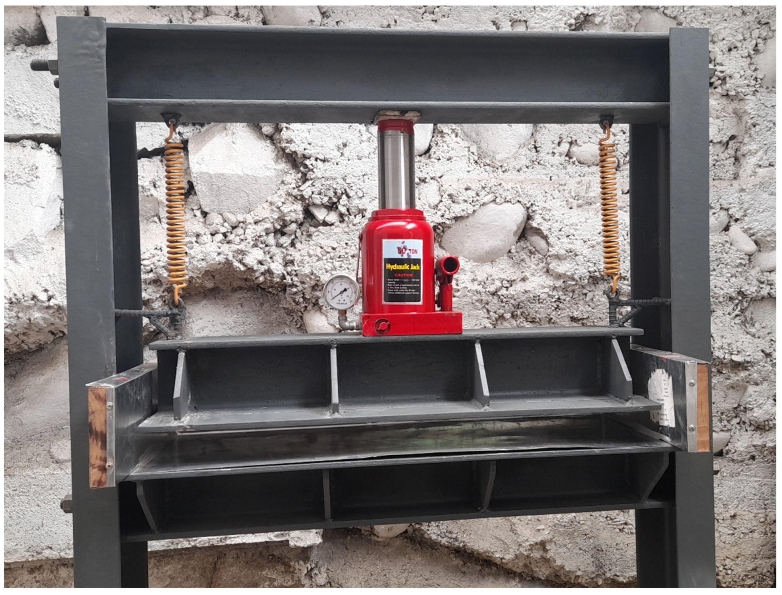
2.3. Compressed Earth Blocks
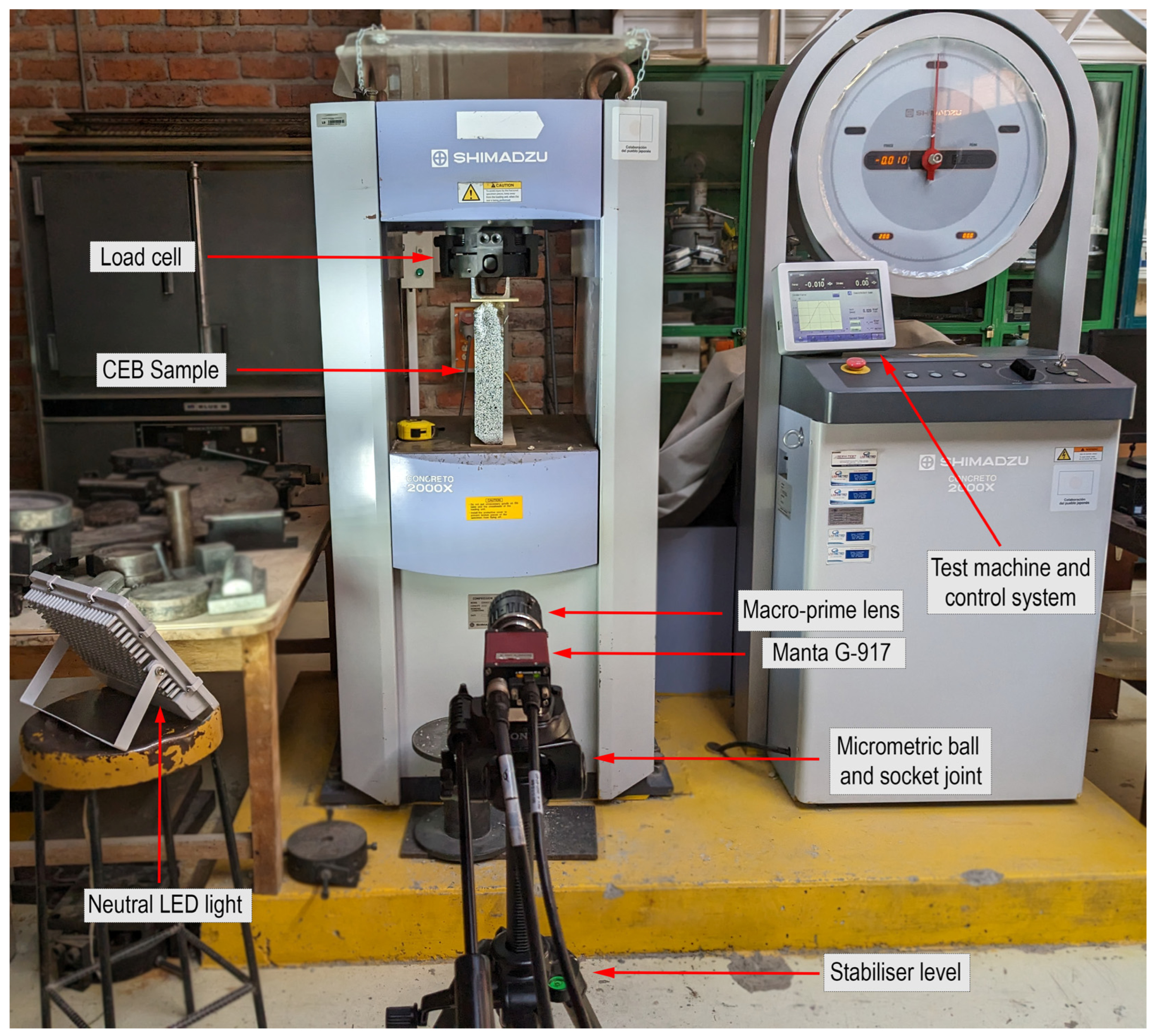
2.4. Mechanical Characterisation of Compressed Earth Blocks
3. Experimental Results and Discussion
3.1. Earth Properties
3.1.1. Empirical Results
3.1.2. Laboratory Results
3.2. Compressed Earth Blocks Properties
3.2.1. Mechanical Results
3.2.2. Characterisation of the Final Solution
4. Economic Analysis
5. Conclusions
- Firstly, empirical and laboratory tests were performed on the types of earth. Based on the results of the granulometry, plasticity and Proctor tests, E_CM earth from the Monay region, whose physical properties best met the standards, was selected.
- Subsequently, CEBs were made with this earth, adding additives of natural origin (bio-fibres) and others that are generally used in construction (lime or cement). Despite the fact that the pressure was not very high, the proposed methodology made it possible to manufacture and test panels of different compositions.
- The manufactured panels were mechanically characterised, obtaining the best results for the cement-stabilised panels. The addition of cement improved the compressive strength. The samples with 5% and 10% cement were the only ones that did not reach the minimum resistance of 2 MPa determined by the regulations. The samples with 15% cement reached a strength of 2.02 MPa. Subsequently, increasing the cement content to 20% improved the strength by 20%. Finally, the 25% cement reached the highest compressive strength, 35% higher than the previous ones. This solution is the most suitable from a structural engineering point of view.
- Among the rest of the non-cement samples, the one with the best results was sample PF_03, composed of 5% glue and 5% ground reed. This solution is the most interesting from an ecological point of view as it uses natural and environmentally friendly additives. This solution is interesting for architectural applications with lower load requirements, such as partitions or thin walls, and for consideration in seismic studies due to its high elongation capacity.
- Based on these results, it was decided to carry out a detailed analysis of these two samples using the digital image correlation technique. The DIC technique made it possible to analyse the displacements and strains in the full field to determine the mode of cracking, obtaining the ultimate strain at the instant prior to failure. Peak strain analysis determined a more homogeneous behaviour for the cement-stabilised samples (PF_06), with a peak strain value of 3.0‰ for a maximum load of 3.3 MPa, while for the samples stabilised with bio-fibres (PF_03), the peak strain was higher, with a value of 5.4‰ for a maximum load of 0.7 MPa.
- Finally, economic analysis was carried out to study the feasibility of manufacturing the panels and their use in housing construction. This analysis showed that CEB is an economically suitable solution, as it allows considerable savings in unit costs per m2 of panel. The cost of a house with the Sandino construction system and this type of panel is 32% lower than the cost of using masonry blocks, 38% lower than using adobe and 94% lower than using conventional bricks.
Author Contributions
Funding
Data Availability Statement
Acknowledgments
Conflicts of Interest
References
- Peduzzi, P. Sand, rarer than one thinks. Environ. Dev. 2014, 11, 208–218. [Google Scholar]
- de Brito, J.; Kurda, R. The past and future of sustainable concrete: A critical review and new strategies on cement-based materials. J. Clean. Prod. 2021, 281, 123558. [Google Scholar] [CrossRef]
- Herrmann, C.J.; Zappettini, E.O. Recursos Minerales, Minería y Medio Ambiente; SEGEMAR: Buenos Aires, Argentina, 2014. [Google Scholar]
- Deboucha, S.; Hashim, R. A review on bricks and stabilized compressed earth blocks. Sci. Res. Essays 2011, 6, 499–506. [Google Scholar]
- Costa, C.; Cerqueira, Â.; Rocha, F.; Velosa, A. The sustainability of adobe construction: Past to future. Int. J. Archit. Herit. 2019, 13, 639–647. [Google Scholar] [CrossRef]
- Font, F.; Hidalgo, P. La tapia en España. Técnicas actuales y ejemplos. Inf. Constr. 2011, 63, 21–34. [Google Scholar] [CrossRef]
- Rigassi, V. Compressed Earth Blocks: Manual of Production; GATE/BASIN: Eschborn, Germany, 1985. [Google Scholar]
- Etzion, Y.; Saller, M. Earth construction—A review of needs and methods. Archit. Sci. Rev. 1987, 30, 43–48. [Google Scholar] [CrossRef]
- Cid, J.; Mazarrón, F.R.; Cañas, I. Las normativas de construcción con tierra en el mundo. Inf. Constr. 2011, 63, 159–169. [Google Scholar] [CrossRef]
- NZS 4297; Engineering Design of Earth Buildings. Standards New Zealand: Wellington, New Zealand, 1998.
- NZS 4298; Materials and Workmanship for Earth Buildings. Standards New Zealand: Wellington, New Zealand, 1998; Volume 569, p. 570.
- ASTM E2392; Standard Guide for Design of Earthen Wall Building Systems. ASTM: West Conshohocken, PA, USA, 2010.
- UNE 41410; Bloques de Tierra Comprimida para Muros y Tabiques. Definiciones, Especificaciones y Métodos de Ensayo. AENOR: Madrid, Spain, 2008.
- Sturm, T.; Ramos, L.F.; Lourenço, P.B. Characterization of dry-stack interlocking compressed earth blocks. Mater. Struct. 2015, 48, 3059–3074. [Google Scholar] [CrossRef]
- McGregor, F.; Heath, A.; Fodde, E.; Shea, A. Conditions affecting the moisture buffering measurement performed on compressed earth blocks. Build. Environ. 2014, 75, 11–18. [Google Scholar] [CrossRef]
- Galíndez, F. Bloques de tierra comprimida (BTC) sin adición de cemento. Segur. Medio Ambiente 2007, 115, 63–73. [Google Scholar]
- Cid-Falceto, J.; Mazarrón, F.R.; Cañas, I. Assessment of compressed earth blocks made in Spain: International durability tests. Constr. Build. Mater. 2012, 37, 738–745. [Google Scholar] [CrossRef]
- IS 13827; Improving Earthquake Resistance of Earthen Buildings—Guidelines. Bureau of Indian Standards: Delhi, India, 1993.
- Gatti, F. Arquitectura y Construcción en Tierra: Estudio Comparativo de las Técnicas Contemporáneas en Tierra; Polytechnic University of Catalonia: Barcelona, Spain, 2012. [Google Scholar]
- Ribeiro, T.; Oliveira, D.V.; Bracci, S. The use of contact sponge method to measure water absorption in earthen heritage treated with water repellents. Int. J. Archit. Herit. 2022, 16, 85–96. [Google Scholar] [CrossRef]
- Vissac, A.; Bourgès, A.; Gandreau, D.; Anger, R.; Fontaine, L. Argiles & Biopolymères-Les Stabilisants Naturaels Pour la Construction en Terre; CRATerre Éditions: Villefontaine, France, 2017. [Google Scholar]
- Losini, A.E.; Grillet, A.C.; Bellotto, M.; Woloszyn, M.; Dotelli, G. Natural additives and biopolymers for raw earth construction stabilization—A review. Constr. Build. Mater. 2021, 304, 124507. [Google Scholar] [CrossRef]
- Teixeira, E.R.; Machado, G.; Junior, A.D.P.; Guarnier, C.; Fernandes, J.; Silva, S.M.; Mateus, R. Mechanical and thermal performance characterisation of compressed earth blocks. Energies 2020, 13, 2978. [Google Scholar] [CrossRef]
- Borri, A.; Corradi, M.; De Maria, A. The failure of masonry walls by disaggregation and the masonry quality index. Heritage 2020, 3, 1162–1198. [Google Scholar] [CrossRef]
- Sánchez-Aparicio, L.J.; Villarino, A.; García-Gago, J.; González-Aguilera, D. Photogrammetric, geometrical, and numerical strategies to evaluate initial and current conditions in historical constructions: A test case in the church of San Lorenzo (Zamora, Spain). Remote Sens. 2016, 8, 60. [Google Scholar] [CrossRef]
- Callaway, P.; Gilbert, M.; Smith, C.C. Influence of Backfill on the Capacity of Masonry Arch Bridges. Proc. Inst. Civ. Eng.-Bridge Eng. 2012, 165, 147–157. [Google Scholar] [CrossRef]
- Sutton, M.A.; Orteu, J.J.; Schreier, H.X. Image Correlation for Shape, Motion and Deformation Measurements: Basic Concepts, Theory and Applications; Springer Science & Business Media: Berlin/Heidelberg, Germany, 2009. [Google Scholar]
- Pisonero, J.; López-Rebollo, J.; García-Martín, R.; Rodríguez-Martín, M.; Sánchez-Aparicio, L.J.; Muñoz-Nieto, A.; González-Aguilera, D. A comparative study of 2D and 3D digital image correlation approaches for the characterization and numerical analysis of composite materials. IEEE Access 2021, 9, 160675–160687. [Google Scholar] [CrossRef]
- Khan, R.M.A.; Shafighfard, T.; Ali, H.Q.; Mieloszyk, M.; Yildiz, M. Strength prediction and experimental damage investigations of plain woven CFRPs with interacting holes using multi-instrument measurements. Polym. Compos. 2023, 44, 3594–3609. [Google Scholar] [CrossRef]
- Teijón-López-Zuazo, E.; López-Rebollo, J.; Sánchez-Aparicio, L.J.; Garcia-Martín, R.; Gonzalez-Aguilera, D. Compression and strain predictive models in non-structural recycled concretes made from construction and demolition wastes. Materials 2021, 14, 3177. [Google Scholar] [CrossRef]
- María, R.-M.; Paula, V.-L.; Jaime, F.-G.; Jorge, L.R. Improvement of tensile properties of carbon fibre-reinforced cementitious matrix composites with coated textile and enhanced mortars. Constr. Build. Mater. 2023, 369, 130552. [Google Scholar] [CrossRef]
- Stazi, F.; Serpilli, M.; Chiappini, G.; Pergolini, M.; Fratalocchi, E.; Lenci, S. Experimental study of the mechanical behaviour of a new extruded earth block masonry. Constr. Build. Mater. 2020, 244, 118368. [Google Scholar] [CrossRef]
- Perić Fekete, A.; Kraus, I.; Grubišić, M.; Dokšanović, T. In-plane seismic performance of rammed earth walls: An eastern Croatia reconnaissance based study. Bull. Earthq. Eng. 2023, 22, 1359–1385. [Google Scholar] [CrossRef]
- El Nabouch, R.; Bui, Q.-B.; Plé, O.; Perrotin, P. Rammed earth under horizontal loadings: Proposition of limit states. Constr. Build. Mater. 2019, 220, 238–244. [Google Scholar] [CrossRef]
- Minke, G. Manual de Construcción en Tierra: La Tierra Como Material de Construcción y su Aplicación en la Arquitectura Actual; Nordan Comunidad: Montevideo, Uruguay, 2001. [Google Scholar]
- E. 080; Diseño y Construcción Con Tierra Reforzada. Ministerio de Vivienda, Construcción y Saneamiento: Lima, Perú, 2017.
- ASTM D422-63; Standard Test Method for Particle-Size Analysis of Soils. ASTM: West Conshohocken, PA, USA, 2007.
- INEN 692; Mecánica de Suelos. Determinación del Límite Plástico. INEM: Quito, Ecuador, 1982.
- ASTM D698; Standard Test Methods for Laboratory Compaction Characteristics of Soil Using Standard Effort. ASTM: West Conshohocken, PA, USA, 2000.
- NTC 5324; Ground Blocks Cement for Walls and Divisions. Definitions. Specifications. Test Methods. Conditions of Delivery. ICONTEC: Bogotá, Colombia, 2004.
- Pan, B.; Qian, K.; Xie, H.; Asundi, A. Two-dimensional digital image correlation for in-plane displacement and strain measurement: A review. Meas. Sci. Technol. 2009, 20, 062001. [Google Scholar] [CrossRef]
- Blaber, J.; Adair, B.; Antoniou, A. Ncorr: Open-source 2D digital image correlation matlab software. Exp. Mech. 2015, 55, 1105–1122. [Google Scholar] [CrossRef]
- Dong, Y.L.; Pan, B. A review of speckle pattern fabrication and assessment for digital image correlation. Exp. Mech. 2017, 57, 1161–1181. [Google Scholar] [CrossRef]
- Pan, B.; Lu, Z.; Xie, H. Mean intensity gradient: An effective global parameter for quality assessment of the speckle patterns used in digital image correlation. Opt. Lasers Eng. 2010, 48, 469–477. [Google Scholar] [CrossRef]
- Lecompte, D.; Sol, H.; Vantomme, J.; Habraken, A. Analysis of Speckle Patterns for Deformation Measurements by Digital Image Correlation. In Speckle06: Speckles, from Grains to Flowers; SPIE: Bellingham, WA, USA, 2006; Volume 6341, pp. 80–85. [Google Scholar]
- Garcia-Martin, R.; López-Rebollo, J.; Sánchez-Aparicio, L.J.; Fueyo, J.G.; Pisonero, J.; Gonzalez-Aguilera, D. Digital image correlation and reliability-based methods for the design and repair of pressure pipes through composite solutions. Constr. Build. Mater. 2020, 248, 118625. [Google Scholar] [CrossRef]


| Nomenclature | City | Zone | Latitude | Longitude |
|---|---|---|---|---|
| E_CC | Cuenca | Challuabamba | −2.859099 | −78.921227 |
| E_CM | Cuenca | Monay | −2.916045 | −78.973492 |
| E_CN | Cuenca | Nulti | −2.866469 | −78.923978 |
| E_PD | Pucará | Deuta | −3.321508 | −79.395789 |
| Nomenclature | Water % | Additive |
|---|---|---|
| PR_01 | 15 | - |
| PR_02 | 15 | - |
| PF_01 | 15 | 5% glue + 5% sawdust |
| PF_02 | 15 | 5% glue + 5% cabuya |
| PF_03 | 15 | 5% glue + 5% ground reed |
| PF_04 | 15 | 5% glue + 5% skeleton reed |
| PF_05 | 15 | 5% glue + 5% totora |
| PC_01 | 20 | 20% lime |
| PC_02 | 20 | 5% cement |
| PC_03 | 20 | 10% cement |
| PC_04 | 20 | 15% cement |
| PC_05 | 20 | 20% cement |
| PC_06 | 20 | 25% cement |
| PO_01 | 15 | 7% asphalt emulsion |
| Test | E_CC | E_CM | E_CN | E_PD |
|---|---|---|---|---|
| Odour | Low level of organic matter | Low level of organic matter | Low level of organic matter | Low level of organic matter |
| Bite | Sandy with clay | Sandy with clay | High level of clay | Sandy with low clay |
| Washing | High level of silt | Sandy with low level of clay | High level of clay | Silty-sandy |
| Cut | Medium level of clay | High level of silt | High level of clay | Medium level of clay as well as silt |
| Ball | High level of clay | Acceptable level of clay | High level of clay | Acceptable level of clay |
| Consistency | High level of clay | High level of clay | High level of clay | High level of clay |
| Nomenclature | Mean (MPa) | Lower Bound (MPa) | Upper Bound (MPa) | CoV (%) |
|---|---|---|---|---|
| PR_01 | - | - | - | - |
| PR_02 | - | - | - | - |
| PF_01 | 0.19 | 0.18 | 0.19 | 3.43 |
| PF_02 | 0.27 | 0.15 | 0.41 | 48.8 |
| PF_03 | 0.65 | 0.41 | 0.94 | 40.9 |
| PF_04 | - | - | - | - |
| PF_05 | 0.07 | 0.07 | 0.08 | 9.8 |
| PC_01 | 0.36 | 0.30 | 0.45 | 20.7 |
| PC_02 | 0.75 | 0.49 | 1.02 | 35.5 |
| PC_03 | 1.61 | 1.41 | 1.78 | 11.7 |
| PC_04 | 2.02 | 1.90 | 2.10 | 5.3 |
| PC_05 | 2.43 | 1.63 | 3.98 | 42.4 |
| PC_06 | 3.28 | 2.84 | 3.59 | 12.5 |
| PO_01 | - | - | - | - |
| Strain Area | Mean (mm/mm) | Lower Bound (mm/mm) | Upper Bound (mm/mm) | CoV (%) |
|---|---|---|---|---|
| Load area | 0.0054 | 0.0033 | 0.0081 | 30.4 |
| Upper | 0.0052 | 0.0033 | 0.0074 | 32.2 |
| Middle | 0.0055 | 0.0040 | 0.0072 | 32.3 |
| Lower | 0.0055 | 0.0035 | 0.0081 | 35.7 |
| Out-of-load | 0.0015 | 0.0010 | 0.0024 | 33.9 |
| Strain Area | Mean (mm/mm) | Lower Bound (mm/mm) | Upper Bound (mm/mm) | CoV (%) |
|---|---|---|---|---|
| Load area | 0.0030 | 0.0022 | 0.0046 | 23.1 |
| Upper | 0.0035 | 0.0029 | 0.0046 | 22.8 |
| Middle | 0.0030 | 0.0023 | 0.0035 | 17.3 |
| Lower | 0.0025 | 0.0022 | 0.0032 | 18.9 |
| Out-of-load | 0.0013 | 0.0010 | 0.0017 | 21.4 |
| Nomenclature | Equipment | Labour | Materials | Total |
|---|---|---|---|---|
| PR_01 | 0.60 | 1.31 | 0.01 | 1.92 |
| PR_02 | 0.60 | 1.31 | 0.01 | 1.92 |
| PF_01 | 0.60 | 1.31 | 2.74 | 4.65 |
| PF_02 | 0.60 | 1.31 | 2.74 | 4.65 |
| PF_03 | 0.60 | 1.31 | 2.74 | 4.65 |
| PF_04 | 0.60 | 1.31 | 2.74 | 4.65 |
| PF_05 | 0.60 | 1.31 | 2.74 | 4.65 |
| PC_01 | 0.60 | 1.31 | 1.90 | 3.81 |
| PC_02 | 0.60 | 1.31 | 0.21 | 2.12 |
| PC_03 | 0.60 | 1.31 | 0.40 | 2.31 |
| PC_04 | 0.60 | 1.31 | 0.59 | 2.50 |
| PC_05 | 0.60 | 1.31 | 0.78 | 2.69 |
| PC_06 | 0.60 | 1.31 | 0.97 | 2.88 |
| PO_01 | 0.60 | 1.31 | 1.97 | 3.88 |
| Material | PC_04 | Brick | Masonry Block | Adobe |
|---|---|---|---|---|
| Image |  | 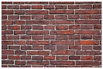 | 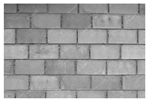 |  |
| Price (EUR/m2) | 7.75 | 15.06 | 10.21 | 10.72 |
| Ratio | 1 | 1.94 | 1.32 | 1.38 |
Disclaimer/Publisher’s Note: The statements, opinions and data contained in all publications are solely those of the individual author(s) and contributor(s) and not of MDPI and/or the editor(s). MDPI and/or the editor(s) disclaim responsibility for any injury to people or property resulting from any ideas, methods, instructions or products referred to in the content. |
© 2024 by the authors. Licensee MDPI, Basel, Switzerland. This article is an open access article distributed under the terms and conditions of the Creative Commons Attribution (CC BY) license (https://creativecommons.org/licenses/by/4.0/).
Share and Cite
López-Rebollo, J.; Cárdenas-Haro, X.; Parra-Vargas, J.P.; Narváez-Berrezueta, K.; Pino, J. Improvement of Mechanical Properties of Compressed Earth Blocks with Stabilising Additives for Self-Build of Sustainable Housing. Buildings 2024, 14, 664. https://doi.org/10.3390/buildings14030664
López-Rebollo J, Cárdenas-Haro X, Parra-Vargas JP, Narváez-Berrezueta K, Pino J. Improvement of Mechanical Properties of Compressed Earth Blocks with Stabilising Additives for Self-Build of Sustainable Housing. Buildings. 2024; 14(3):664. https://doi.org/10.3390/buildings14030664
Chicago/Turabian StyleLópez-Rebollo, Jorge, Xavier Cárdenas-Haro, Juan Pablo Parra-Vargas, Kevin Narváez-Berrezueta, and Julver Pino. 2024. "Improvement of Mechanical Properties of Compressed Earth Blocks with Stabilising Additives for Self-Build of Sustainable Housing" Buildings 14, no. 3: 664. https://doi.org/10.3390/buildings14030664
APA StyleLópez-Rebollo, J., Cárdenas-Haro, X., Parra-Vargas, J. P., Narváez-Berrezueta, K., & Pino, J. (2024). Improvement of Mechanical Properties of Compressed Earth Blocks with Stabilising Additives for Self-Build of Sustainable Housing. Buildings, 14(3), 664. https://doi.org/10.3390/buildings14030664