Article

Seismic Performance Evaluation of Reinforced Concrete Building Structure Retrofitted with Self-Centering Disc-Slit Damper and Conventional Steel Slit Damper

1
Department of Civil Engineering, University of Management and Technology (UMT), Lahore 45000, Pakistan
2
Department of Civil Engineering, Balochistan University of Information Technology, Engineering and Management Sciences (BUITEMS), Quetta 87300, Pakistan
3
Earthquake Research Institute (ERI), University of Tokyo, Tokyo 113-0032, Japan
4
Department of Architectural Engineering, Seoil University, Seoul 06978, Republic of Korea
*
Authors to whom correspondence should be addressed.
Buildings 2024, 14(3), 795; https://doi.org/10.3390/buildings14030795
Submission received: 18 February 2024 / Revised: 7 March 2024 / Accepted: 12 March 2024 / Published: 14 March 2024
(This article belongs to the Section Building Materials, and Repair & Renovation)

Abstract

:
To meet the recent requirements of low-damage design, there is a growing need to retrofit building structures with a self-centering dissipation system. This system serves a dual purpose: reducing lateral drift and providing supplemental damping to enhance the seismic performance of buildings. This research focuses on assessing the efficiency in seismic response of structures retrofitted with an innovative self-centering hysteretic damper called a Self-Centering Disc Slit Damper (SC-DSD). The SC-DSD consists of four slit dampers and pre-compressed Belleville disc springs that provide self-centering and energy dissipation capabilities. This study investigates the SC-DSD’s working mechanism, theoretical formulation, and design method of SC-DSD dampers for their application in multistory building structures. A reinforced concrete (RC) structure is selected as a case study building that is retrofitted with SC-DSDs and conventional slit dampers. Subsequent seismic performance assessments are conducted using detailed pushover to evaluate the global behavior and capacity of the structure used for the design of the damping system. Nonlinear time history analysis is performed to simulate the dynamic behavior of the retrofitted structure under a variety of seismic excitations. This analysis considers a range of ground motion records to capture different intensity levels and frequency content. Comparing these analyses reveals that the designed SC-DSDs effectively reduce seismic responses while minimizing residual displacement up to 95% when contrasted with both the bare structure and the structure retrofitted with conventional steel slit dampers.

1. Introduction

Recent advances in manufacturing techniques and the construction sector have enabled the development of innovative and advanced structural systems that not only protect buildings from residual lateral drifts during severe earthquakes but also restore the structure to its original state. These advancements are integrated into building structures as seismic dampers [1], encompassing a variety of solutions such as fluid viscous dampers [2], sliding-friction dampers [3], hysteretic yielding dissipation devices [4,5], base isolators [6], buckling restrained braces [7], and hybrid systems [8]. These seismic protection systems are employed to enhance the seismic resilience of structures, safeguarding their primary structural components against seismic forces. Self-centering dissipation systems are being developed, and active research is opening new avenues for superior seismic resilience. Typically, these systems use conventional dampers connected to prestressed tendons, springs, or shape memory alloys to achieve energy dissipation and impart recentering forces to buildings to counter earthquake-induced forces [8,9,10,11,12,13,14,15,16,17,18]. The fundamental concept remains similar, with the objective of inducing a flag-shaped hysteresis in the force-deformation relationship of the critical elements.
The metallic slit damper, due to its easy design, manufacturing, and excellent stable hysteretic behavior, has an important position in seismic retrofitting strategies. Chan and Albermani provided the initial guideline and conducted the cyclic test on a steel plate slit damper, which is the most common type [19]. The potential issue with slit dampers is a reduction in energy dissipation capacity due to the yielding of steel struts. Naeem and Kim [20] proposed a novel adaptation of the slit damper that addresses this issue. It is called a multi-slit damper (MSD) and is made up of three steel sheets of a story height with interconnected weaker and stronger slit dampers arranged sequentially, each possessing distinct stiffness and yield strength. During mild to moderate earthquake ground motions, the MSD dissipates energy by allowing the weaker slit damper to yield while the stronger segment remains within its elastic limits. In cases of severe ground motions, additional displacement of the weaker segment is prevented by a stopping mechanism, redirecting the force entirely to the stronger portion of the damper to prevent support breakage. Javidan et al. [21] performed an experimental study on MSDs in RC frame structures, conducting full-scale tests of concrete frame structures with and without MSDs and checking the seismic responses of school-reinforced concrete structures by implementing MSDs. The slit damper dissipation capacity and post-yield stiffness were enhanced by combining the slit damper with rotational friction dampers, as studied by Lee and Kim [22]. Lee and Kim [23] developed the “box-shaped slit damper”, consisting of four strategically positioned slit dampers within a square steel section, designed to maximize energy dissipation in a confined area.
In recent developments, disc springs have been utilized to improve the recentering effect within hysteretic dampers. A self-centering brace with a friction device in combination with disc springs to provide sufficient recentering to the braces and friction damper was developed by W. Wang et al. [24]. By utilizing various configurations of prestressed disc springs for providing recentering and adjusting the frictional force, the system provides adaptable load resistance, deformability, and diverse hysteretic shapes; this self-centering friction brace was further investigated in [25]. The Resilient Slip Friction Joint (RSFJ), as described in references [26,27], integrates both recentering and energy dissipation functionalities within a single damping system. This is achieved through the incorporation of grooved outer plates, slotted middle plates, and pre-stressed disc springs. The RSFJ’s adaptability across various structural systems makes it a versatile self-centering supplemental damping device that is suitable for high seismic demands. A novel self-centering bracing system using friction energy dissipation devices and pre-pressed combination disc springs for self-centering is developed in [28]. Experimental validation confirms stable energy dissipation, excellent self-centering capability, and accurate prediction of mechanical behavior. The study by Jafari et al. [29] investigated the impact of a mild steel bar layout on the seismic performance, damage, collapse probability, and seismic risk of hybrid self-centering walls (HSWs), aiming to address the energy dissipation deficiency inherent in self-centering walls.
Recently, Naeem et al. [30] developed a novel self-centering slit damper that is inspired by the simple design of a slit damper with high energy dissipation and recentering capability of disc spring during large deformations. This recentering hysteretic steel slit damper (SC-DSD) consists of four slit dampers trimmed into a hollow structural steel section and connecting them with an inner moving section and stacking of prestressed disc springs for recentering force. The assembly of the SC-DSD is such that the slit damper can come to its original position after cyclic loading. In this research, the efficacy of the SC-DSD is further investigated analytically by using a case-study model of an archetype-reinforced concrete structure retrofitted with the SC-DSDs. The analytical model and the design methodology of the SC-DSD to retrofit the structure are described. In the second case, a similar structure is retrofitted with the conventional slit damper (SD) to meet the same target performance. The seismic performance of the model structures is comprehensively assessed through rigorous nonlinear dynamic analyses. Specifically, these analyses simulate the response of the structures retrofitted with SC-DSD and compare it with both the bare structure and a structure retrofitted with conventional Steel Slit Dampers. The findings demonstrate the efficacy of the SC-DSD in dissipating seismic energy and mitigating structural responses. Notably, compared to the bare and conventionally retrofitted structures, the SC-DSD retrofit significantly reduces residual lateral drift, inter-story drift, and roof displacement, particularly under severe ground motions. These results signify the substantial seismic performance enhancement afforded by the SC-DSD retrofitting technique.

2. Self-Centering Damper and Analytical Model

This section initially outlines the specifics of the Self-Centering Disc-Slit Damper (SC-DSD), followed by an explanation of its theoretical framework established in prior research by Naeem et al. [30]. Based on the theoretical formulation, the analytical macro model of the SC-DSD formulated in structural modeling and analysis software is discussed. This model is subsequently applied to assess the seismic retrofitting and design of a case study reinforced concrete structure. The validation process involves verifying the hysteresis loop of the analytical model through cyclic loading tests performed on the damper.

2.1. Configuration of SC-DSD

The components and assembly progression of the SC-DSD are depicted in Figure 1. Four steel slit dampers, specifically designed for the prototype, are incised on each facet of the boxed-shaped hollow structural section. The open end (moving end) of each slit dampers are welded to the interior boxed-shaped steel section. Two stacks of disc springs, pre-tensioned and situated within both the outer and inner sections, are also depicted in stage 3. The assembly of the damper is finalized by connecting the top plate to the inner steel section using M-10 high-strength bolts. Figure 2 provides an overview of the dimensions of the slit damper and disc spring components. The distinctive attributes of the material utilized for the slit damper and springs are enumerated in Table 1.
The induced energy is dissipated as the steel strips yield due to the relative movement between the outer and inner sections, with the recentering force provided by the prestressed stacks of disc springs on both sides. The stiffness and yield strength of slit dampers can be calculated using Equations (1) and (2) [19]. The prestress force of the disc spring should be equal to or larger than the yield strength of the slit damper in order to provide the self-centering ability to the SC-DSD; the restoring force from the disc springs is calculated based on Equation (3).
K s = 4 ( n 12 E I l o 3 ) = 4 ( n E t b 3 l o 3 )
F y , s l i t = 4 ( 2 n M p l o ) = 2 n σ y t b 2 l o
F r   = m 1 f M ( m 1 ) f R 4 E 1 μ 2 t s 3 M 1 D 2 M 4 2 f t M 4 2 h 0 t f t h 0 t f 2 t + 1
where Ks is the elastic stiffness of the four slit dampers; n is the number of steel strips; b and t are the width and thickness; l is the length of the steel strips; Fy is the yield strength of the slit dampers; Fr is the restoring force provided by the disc springs. Further details about the above design equations can be found elsewhere [31,32].

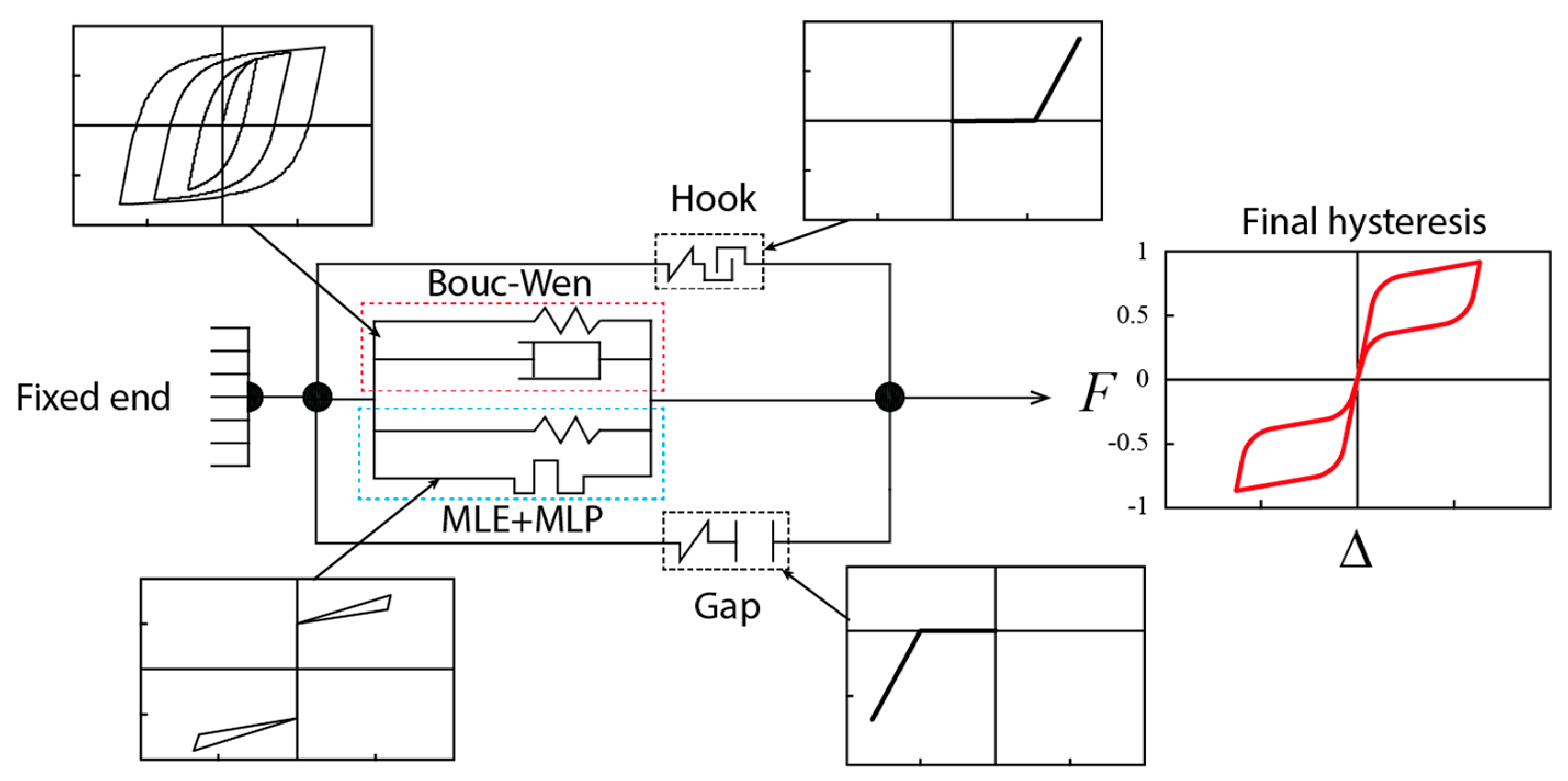
2.2. Cyclic Loading Test and Analytical Model

The unique feature of self-centering flag-shaped hysteresis is that it has multiple stiffnesses within one loop. The stiffness during the loading cycle is determined by the prestressed force of the disc-spring stack and the initial elastic range of the slit damper. There are a few assumptions to make the calculation simple, which are as follows: the axial strains of the threaded rods, bolts, and top and limiting plates are neglected, frictional forces between the inner and outer box are excluded, and the deformations of the load transferring components like braces are not considered after the SC-DSD device is activated.
The analytical macro model is shown in Figure 3. There are three nonlinear links combined to form the model in the structural analysis software known as “Perform 3D V 8.0”. These links represent the behavior of the slit damper using the Bouc–Wen model [33], consisting of a dashpot combined with spring. At the same time, the multi-linear elastic (MLE) and multi-linear plastic (MLP) are combined to produce the behavior of the prestressed disc springs. These links are built into most of the structural analysis software for practicing engineers. Figure 3 also depicts the behavior of each link to achieve the recentering hysteresis loop. Gap and hook links are used to control the maximum stroke displacement of the damper under tensile and compressive forces. The simplification of the analytical model is useful in providing the computational efficiency required for the nonlinear dynamic analysis of large building structures in practice [34,35].
A cyclic loading test was conducted to acquire the hysteresis data of the SC-DSD, which was then compared to the results obtained from the analytical macro-model. As can be observed in Figure 4a, the hysteresis depicts the flag-shaped hysteresis. The maximum bearing force of the specimen obtained at 10.9 mm was 264 kN in both tension and compression. During the loading cycle, the damper activated at 64 kN, which was the prestress force on the disc springs, and the slit dampers started to yield at 128 kN. The loading protocol selected for the test is FEMA 461 [36]. The residual deformation was reduced to 0.5 mm for the first 10 cycles. However, due to external frictional forces, it went to 2.6 mm for larger displacement. The analytical model is able to predict the behavior of the damper accurately. The hysteretic curve obtained from the analytical model is superimposed on the experimental results. It shows the agreeable prediction for the calculation of bearing capacity, energy dissipation capacity, and residual deformation. The frictional forces between the inner and outer sections are ignored in the analytical model. Figure 4b shows the deformed steel strips during the experiment. Further details about the prototype and the experiments are discussed elsewhere [30].

3. Seismic Retrofitting of Structure with SC-DSDs

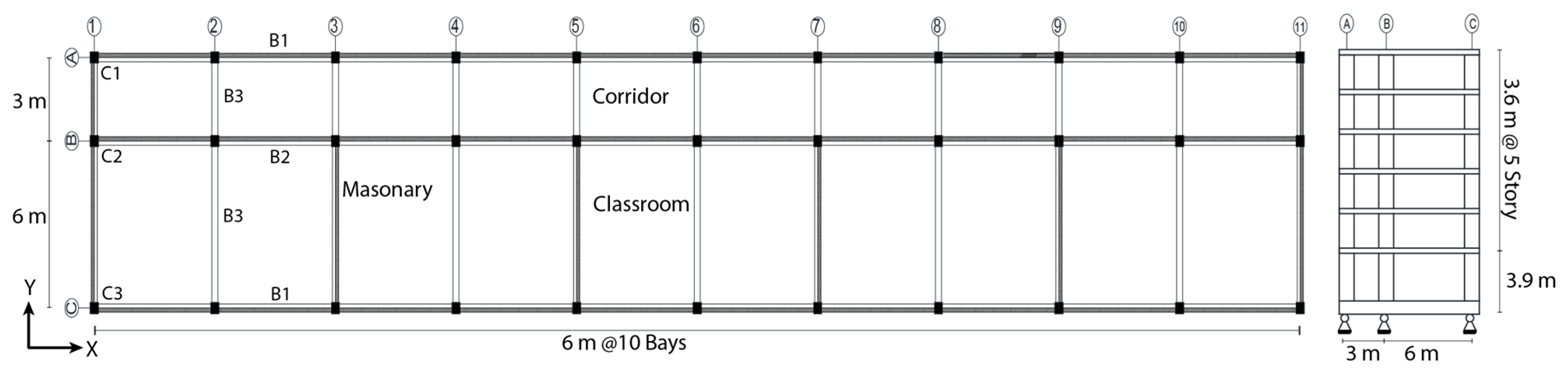
3.1. Structural Modeling of Archetype Building Structure

In this section, we undertake structural modeling to assess the efficacy of the SC-DSD as a retrofitting method for a Reinforced Concrete (RC) structure. Our focus is on a specific case study of an archetype school building constructed in the 1980s without seismic design considerations. Situated in the high-seismic zone of Los Angeles, California, this building comprises a six-story RC structure utilizing an ordinary moment frame system. The initial story stands at a height of 3900 mm, while the subsequent five stories measure 3600 mm in height each. There are two bays in the y-direction for classrooms and corridors, while in the longitudinal (x-direction), there are 10 bays with a length of 6000 mm. The plan layout of the structure is shown in Figure 5, and the details of the sectional properties and reinforcement bars used in the beams and columns of structures are mentioned in Table 2 and Table 3, respectively.
A dead load of 3.0 kN/m2 is applied to the classrooms and corridors. The live load is selected from the Minimum Design Loads for Buildings and Other Structures (ASCE 7-22) [37], which are 1.91 kN/m2 for classrooms and 3.83 kN/m2 for corridors. The load of brick masonry infill walls is considered based on 114 mm thick infills walls.
The concrete exhibits a nominal compressive strength of 18 MPa, with an ultimate compressive strength of 22.5 MPa and an ultimate strain of 0.002. The residual strength of the concrete is defined as 20% of its nominal compressive strength, as depicted in Figure 6a. Meanwhile, the steel reinforcement bar has a yield strength of 300 MPa, depicted by a bilinear curve in Figure 6b.
The beam element consists of inelastic end rotation moment hinges connected with the elastic segment; the relationship of the moment hinge is defined according to the ASCE/SEI 41-13 [38], as shown in Figure 7a. According to ASCE/SEI 41-13, it is suggested to decrease both the flexural and shear stiffness of the beam to 50% and 40%, respectively, from their original values. Similarly, the flexural stiffness of the columns is modified to half of their initial values, considering the axial loads they resist. The cyclic performance of the analyzed columns is depicted in Figure 7b. Masonry infill walls are not considered in the analysis to save the computational cost. Further details about the nonlinear modeling of RC structures can be found in the user manual of Perform 3D software [39].
The modal damping ratio is taken at 5% for the analyses. Determined through modal analysis and considering the effective stiffness, the structure’s natural periods in the longitudinal direction are found to be 2.2 s. Subsequently, the seismic performance of the structure is examined, and seismic retrofitting strategies are formulated. The first scenario involves implementing the SC-DSD, while the second scenario employs conventional SD.

3.2. Nonlinear Static Analysis

The capacity-demand spectrum method (CSM), specified in ATC 40 [40], is used to obtain both the performance point of the structure and the requisite effective damping ratio necessary to achieve the target performance level corresponding to a specified capacity and demand curve. The advantage of CSM is the ability to predict structural response accurately, even without running the nonlinear dynamic analysis on a model structure, while still considering the inherent nonlinearity of the structure.
To evaluate the capacity of the original RC frame structure, the nonlinear static pushover analyses are employed, applying lateral loads in proportion to the fundamental modal shape until the maximum inter-story drift reaches 4% of the height of each story. Figure 8 illustrates the pushover curve, representing the nonlinear relationship between force and displacement along the longitudinal axis of the modeled structure. Transforming this pushover curve yields the capacity spectrum. Meanwhile, the demand curve is derived from the design response spectrum specific to Los Angeles, California. The performance point dp is calculated at the intersection point of the reduced demand spectrum using β e f f and capacity spectrum curves. The structure’s dp prior to seismically retrofitting with dampers is located at a spectral displacement of Sd 174.8 mm for the Design Basis Earthquake (DBE) hazard level. Additionally, the roof displacement of the structure is measured at 387 mm, indicating a maximum inter-story drift ratio of approximately 1.76%, estimated through the analysis of the mode shape vector. The seismic performance capacity of the original structure is not sufficient to meet the life safety limit state of 1% drift ratio at the (DBE) hazard level. The new performance point is obtained iteratively by modifying the demand curve until convergence. The effective period of the original bare frame structure in the longitudinal direction is calculated to be 3.2 s using the formula shown in Equation (4):
T e f f = T i K i K e
where T i represents the fundamental period in the longitudinal direction under consideration in this case, and it is calculated by elastic dynamic analysis. K i is the lateral elastic stiffness, while K e denotes the effective stiffness of the whole structural system.
In the event that a target drift of 1% of the story height is experienced in each story, the roof-story displacement of the modeled structure reaches 225 mm. The Sd, is calculated to be 101.6 mm utilizing the following Equations (5) and (6):
S d = Δ Roof   P F 1 × ϕ Roof , 1
P F 1 = i = 1 N   m i ϕ i 1 i = 1 N   m i ϕ i 1 2
here Δ R oof   represents the displacement at the roof level, P F 1 denotes the modal participation factor associated with the first natural mode, ϕ R o o f , 1 and ϕ i 1 , respectively, refer to the components of the first mode shape vector corresponding to the roof, i t h , N signifies the total number of stories, and m i is the associated modal mass for the i t h mode.
Through the application of the approximate CSM, it is noted that a spectral displacement of 101.6 mm is attained by elevating the effective damping ratio, β eff , to 34% of the critical damping. The structure provides a damping ratio of 5% + κβ0 = 15% at the considered target performance point, where 5% is considered inherent damping. Additional effective damping must be supplied by damping devices to meet the performance limit state of 1% of the story height. The total amount of the SC-DSD systems required to meet the objective performance is computed through the effective damping equations referenced in ASCE/SEI 41-13 [38]:
β e f f = 5 % + κ β 0 + j   W j 4 π W k
W k = 1 2 F i Δ i
where W j is the work carried out by the j th damper in one complete cycle which is equal to the area inside the hysteresis curve; Wk is the maximum strain energy of the structure at the performance point; F i and Δ i are, respectively, the imposed lateral seismic force and the corresponding displacement at the seismic weight of the i th floor. These parameters can be obtained using the lateral forces and the story displacements at the performance point.

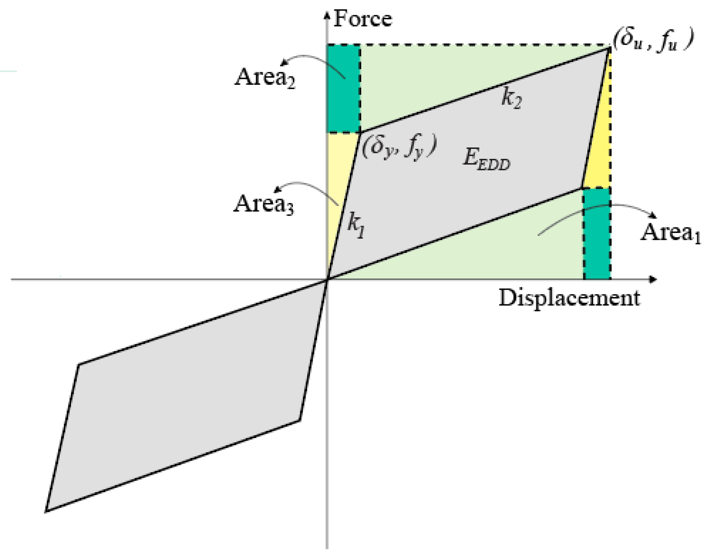
3.3. Design of Self-Centering Disc Slit Damper

The core principle guiding the design of the SC-DSD is to enable the structure to withstand the DBE level shaking without inelastic straining of columns and beams to avoid excessive permanent lateral drift. The retrofitted structure must provide the required added stiffness, damping, and dissipation capacity to satisfy the performance point corresponding to the maximum inter-story drift ratio (MIDR) of 1.0%, which is the Life Safety (LS) limit state.
The estimated effective damping required to meet the target performance is achieved through energy dissipation provided by dampers of unspecified size. The installation of dampers within the structure involves the use of diagonal braces set at a 30° angle relative to the beams. The axial displacement of the slit damper, corresponding to an inter-story drift ratio of 1%, is determined to be 30.5 mm, serving as the SC-DSD device’s stroke. The work done or energy dissipated by the damper in one cycle is the area in the idealized hysteresis curve, as shown in Figure 9. It is assumed that the prestressing force is equal to the yielding force of the four slit dampers, which is obtained as follows:
W j = 2 f u δ u 2   Tri - Area   1 2   Rec - Area   2 2   Tri - Area   3 = 2 f y δ u f u δ y
f y = n σ y t b 2 2 l 0 , δ y = σ y l 0 2 2 b E
f u = f y + δ u δ y K 2 , δ u = H 1 θ cos φ
where W j denotes the energy dissipated per cycle of a damper, corresponding to the area enclosed by the idealized hysteresis curve depicted in Figure 9; H1 is the story height; θ is the lateral drift angle; and φ is the angle of connecting brace with the beam. The expression within the parentheses in Equation (9) [41] represents half of the total area enclosed by the hysteresis curve and can be reformulated as shown in Equation (12):
W j = 2 ( α + 1 ) f y δ u δ y = 2 ( α + 1 ) n σ y t b 2 2 l 0 H 1 θ cos φ σ y l 0 2 2 b E
Based on the previously derived dissipated energy, the effective damping ratio of the structure utilizing the SC-DSD connection with a brace can be articulated in the following manner as mentioned in Equation (13):
β e f f = 5 % + κ β 0 + j     2 ( α + 1 ) n σ y t b 2 2 l 0 H 1 θ cos φ σ y L 0 2 2 b E 2 π i     F i Δ i
Assuming the length of steel strip in the slit damper ( l 0 ) is 100 mm, the yield stress σ y is 400   M P a , the tensile strength 590 MPa, the width of the strip b is 10   m m , the necessary steel section thickness ( t ) is required to satisfy the effective damping of 19% is estimated to be 10.8   m m . As a result, the retrofit design specifies a thickness of 12 mm for the steel plates, with each slit damper containing 8 steel strips, with a total of 32 strips. To provide sufficient restoring force to the damping device, the two stacks of 150 mm diameter with a thickness of 8 mm are selected. Each stack of pre-compressed springs within the SC-DSD comprises 16 disc springs arranged in a parallel layout, with 8 steps arranged in series to achieve a displacement of 30 mm.
In the second case, a similar RC structure is retrofitted with the conventional SD. The initial stiffness, yield strength, and stroke of the conventional SD are equal to the SC-DSD. However, after yielding the stiffness is degraded to 10% of the initial stiffness. In the conventional SD, there are no disc springs, meaning that the recentering capability is not considered.
The number of SC-DSDs is approximated using the above procedure, which provides the required damping to satisfy the target inter-story drift ratio of 1%. It is estimated that a total of 52 dampers can provide sufficient dissipation and restore force to the structure under DBE-level shaking. In order to keep the symmetry when placing the dampers in the structure, 26 dampers are installed on each exterior frame. The retrofitting schemes are applied in the longitudinal direction in the exterior frames of the model structure, as shown in Figure 10, with dampers installed at the two lower corners of two consecutive bays. However, it is important to mention that as there are simplifications in the above process, the required damping obtained is not of optimum value but on the conservative side. The seismic performance of the model RC structure before and after retrofitting with the proposed SC-DSD and conventional SC is evaluated and discussed in detail in the next section.

4. Comparative Seismic Performance Analysis of Original and Retrofitted Structures

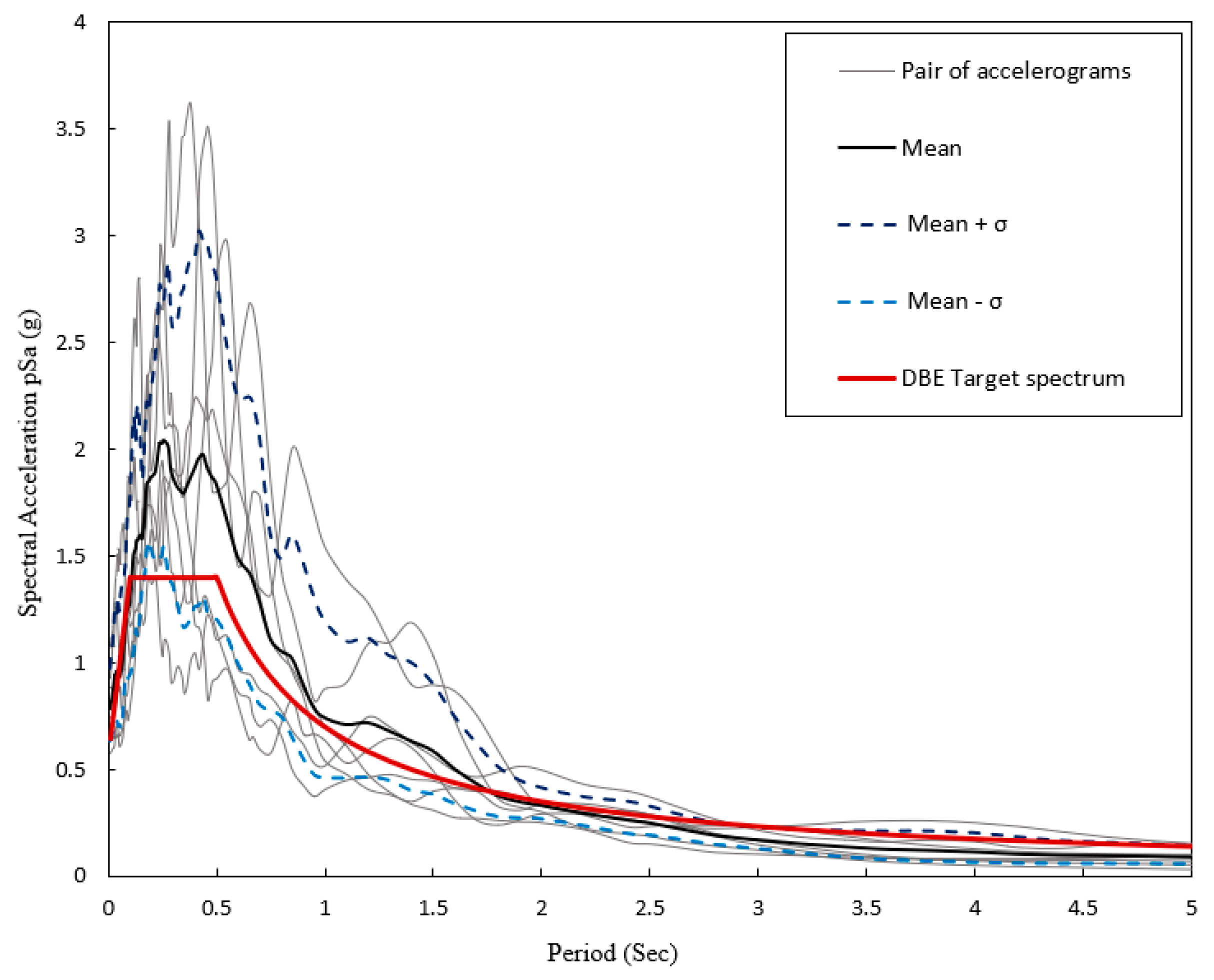
4.1. Ground Motion Records

The model structure is assumed to be located in the high seismic zone of Los Angeles (34° N, 118.2° W), California. The spectral acceleration at short period is S D S = 1.4   g and the spectral response acceleration at 1.0 s is S D 1 = 0.7   g , for the DBE response spectrum, as mentioned in ASCE 7-22 [38]. The selected ground motion records used for nonlinear time history analysis are scaled for the DE level of the site-specific response spectra, as presented in Figure 11. They were scaled according to the ASCE guidelines, ensuring that within the period range of 0.2 T to 1.5 T , where T represents the fundamental period. The average SRSS (Square Root of the Sum of the Squares) spectra across all ground motion records remained above 90% of the target response spectrum. The details of seven selected ground acceleration records provided by the PEER NGA database [41], such as their peak ground acceleration (PGA), depth, and average shear velocity, are summarized in Table 4.
The engineering demand parameters (EDPs) of bare original structures and retrofitted structures are compared for detailed performance evaluation. The EDPs are drift ratio, residual displacement, maximum roof displacement, and energy dissipation in the main component of buildings after the selected ground motions are applied.

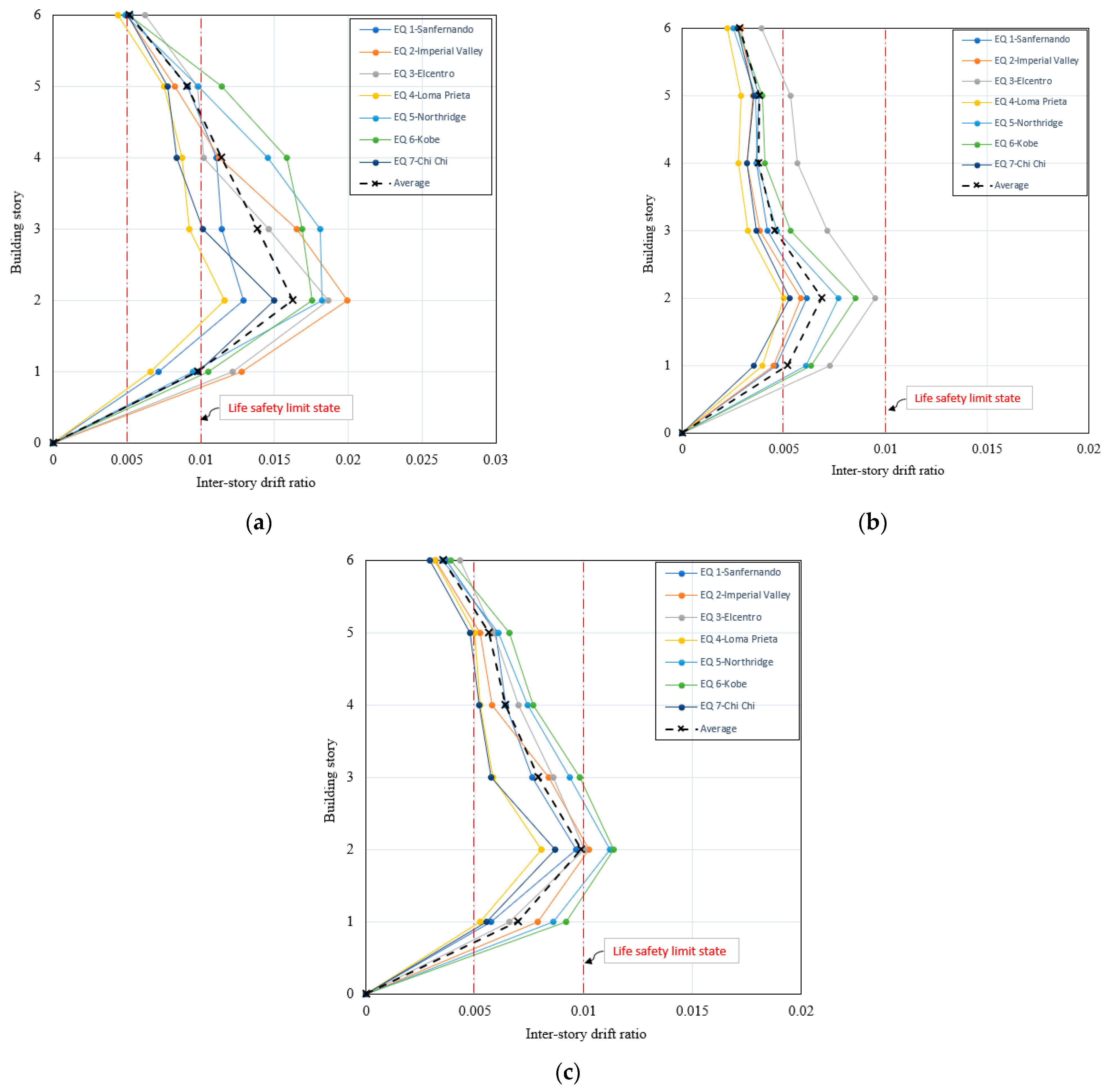
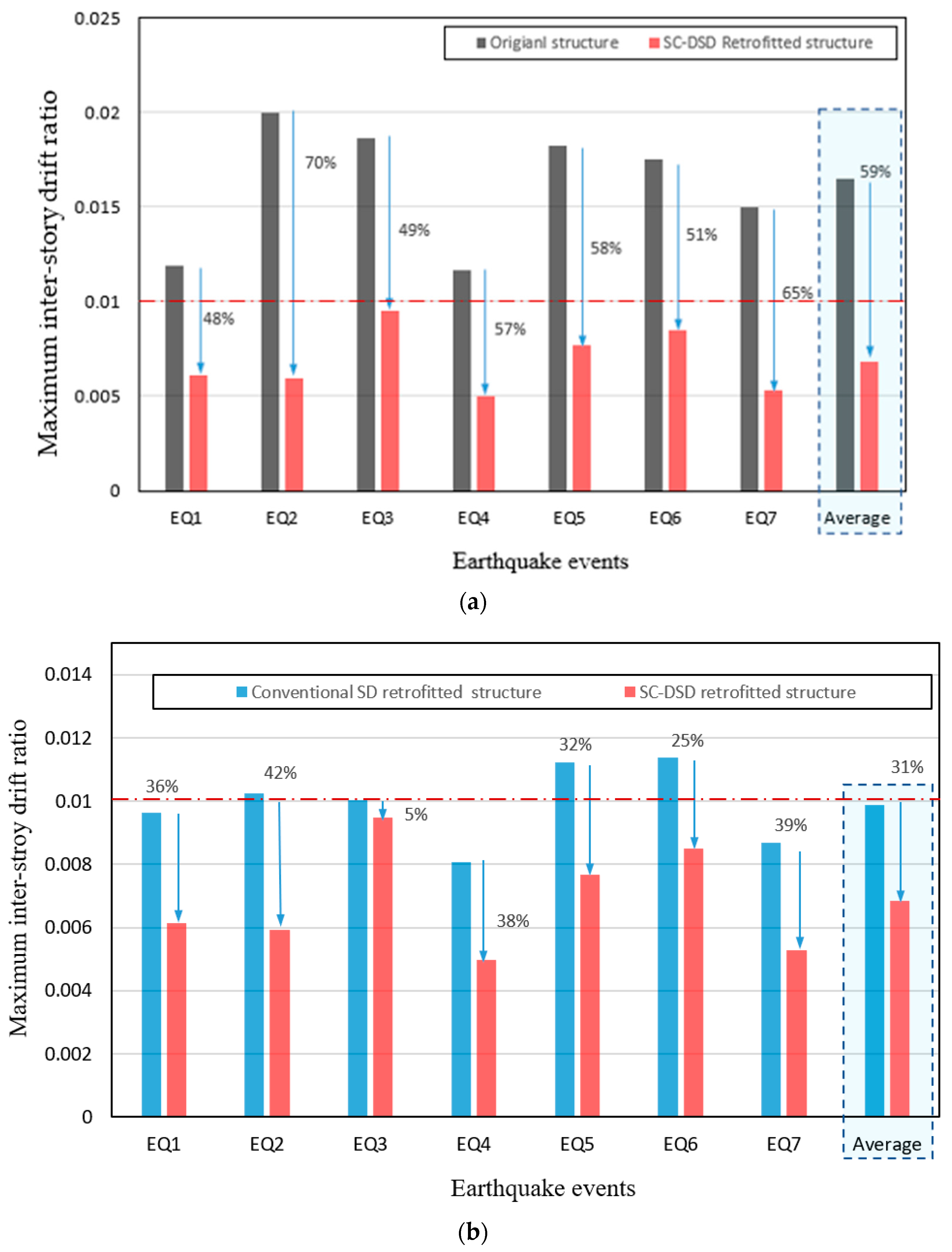
4.2. Analysis and Results from Nonlinear Time History Simulation

The maximum inter-story drift ratios (MIDR) observed in the original structure prior to implementing the proposed retrofitting schemes are shown in Figure 12a, and it is seen that the second and third stories are more critical. The MIDR ranges between 1.16% and 2.0%, with a mean value of 1.66%. This finding aligns with the inter-story drift ratio of 1.76% derived from the nonlinear pushover analysis. The maximum target drift ratio of 1% is considered the life safety limit state for a hospital or a school building according to ATC 40 [40], and the original structure exceeds the target limit state performance level.
The existing building structure, which is used as the case study in this research, is retrofitted with the SC-DSD, and the same building also undergoes retrofitting with conventional SD. The performance of these retrofitted structures is evaluated using the same set of seven ground motion records employed for assessing the seismic performance of the original, bare frame structure. Figure 12b,c illustrate the MIDR observed in the structures post-retrofitting with the SC-DSD and conventional SD, respectively. Results indicate that the MIDR ranges from 0.48% to 0.95%, with a mean value of 0.67% for the SC-DSD retrofit. Conversely, the mean maximum inter-story drift ratio for the structure retrofitted with the conventional SD is 0.97%, nearing the target performance level. However, retrofitting with the conventional SD failed to meet the target performance criteria under EQ5 and EQ6. Notably, the inter-story drift ratios displayed in Figure 12 exhibit a more uniform distribution across both retrofitted structures.
Upon comparing the inter-story drift ratios depicted in Figure 13a,b, it becomes evident that the SC-DSD exhibited superior performance during strong excitation, attaining the intended performance level of structure. The average maximum inter-story drift ratio of the structure after the implementation of SC-DSD is 59% less compared to the original structure. Moreover, Figure 13b shows that even though the designed conventional SD achieved the objective performance, its maximum inter-story drift ratio is 31% higher compared to the SC-DSD. The enhanced performance of the SC-DSD compared to the SD is attributed to the integration of disc springs within the slit dampers. Enhancing post-yield stiffness and providing improved restorative force contribute to enhancing the overall performance of the damper.
The model structure’s roof displacement time histories, before and after seismic retrofitting with the SC-DSD and conventional SD, are illustrated in Figure 14 and analyzed under specific ground motion scenarios. The enhancement in the seismic performance of the structure is observed after the installation of the SC-DSD, resulting in notable reductions in both maximum displacements and permanent residual deformation. The most prominent influence of the SC-DSD on the seismic response of the structure is significantly diminishing the residual deformation of the structure after the shaking. The residual deformations of the original structure under the excitation of Imperial Valley ground motion and El Centro ground motion were 30 mm and 36 mm. After the application of the SC-DSD, the residual deformation reduced to 2 mm and 10 mm, respectively. The maximum reduction in the residual deformation of the model structure is observed in the case of the Northridge earthquake, which was reduced from 101 mm of the original structure to 5 mm after retrofitting with SC-DSD.
The recentering ability of the SC-DSD compared to the conventional SD can be also observed in Figure 14, as the residual displacement in the structure with conventional SD is higher. The application of conventional SD reduces the residual displacement by up to 50% compared to the original structure in four of the ground motions. However, in the case of El Centro, it was 9 mm higher. This depicts the downside of conventional slit dampers. After the fracture of the slit damper, the earthquake-induced forces are transferred to the main structural members and hence forming hinges, and the structure cannot come to its original position.
The maximum roof displacements obtained from the nonlinear time history analyses are compared in Figure 15. By comparing the seismic performance of the retrofitted structure to the original structure, the maximum roof displacement is reduced up to 62%, from 26.5 cm to 10 cm in the case of the Northridge ground motion. By retrofitting the original structure when excited under the DBE level shaking, the average maximum roof displacement is reduced up to 53% with the application of the SC-DSD, as depicted in Figure 15. Both retrofitting systems reduce the maximum roof displacement compared to the original structure under the selected ground motions. Moreover, the structure retrofitted with the SC-DSD shows an average maximum roof displacement of 31% less compared to the structure retrofitted with the conventional SD.
The added stiffness due to disc springs to the box slit dampers in the proposed device also causes an increase in floor accelerations even after the yielding of the damper, as indicated in Figure 16. An average increment of 9% was observed in the floor accelerations during the excitation compared to the original structure, and an average increment of 13% was observed compared to the structure retrofitted with the conventional SD.
The seismic performance comparison of the SC-DSD retrofitted structure with the bare structure and the conventional SD retrofitted structure involves quantifying the inelastic energy dissipation capacity under DBE-level ground motions. The energy dissipation by the dampers for each seismic event is obtained by integrating the area under the hysteresis loops. The total inelastic energy dissipation ranges from 650 kJ to 2489 kJ for the seven earthquake records.
The dissipated inelastic hysteretic energy during the nonlinear time history analysis of the original and retrofitted structures, when subjected to the Northridge earthquake record, is reported as an example in Figure 17. The total dissipated inelastic energy of 852 kJ in the original structure is shown in Figure 17a. Analysis results indicate that 68% of the input seismic energy is dissipated in the column elements through inelastic deformation during hinge formation, while the beam elements dissipate the remaining 32%. This is a common weak-column and strong-beam behavior of conventional building structures that lack seismic design considerations.
Compared to the bare structure and the conventional SD retrofitted structure, the SC-DSD retrofitted structure dissipates a total of 996 kJ of inelastic energy. As shown in Figure 17b, 86% of this total inelastic energy is consumed by the SC-DSD devices, whereas the remaining energy is distributed to the structural elements. The structure equipped with the conventional SD is able to dissipate 74% of the total 1072 kJ inelastic energy, according to Figure 17c. Model structures retrofitted with the SC-DSD and conventional SD prevent the formation of plastic hinges in the primary structural elements and dissipate the seismic energy effectively by lowering the seismic demand on the building structure. Applying self-centering seismic fuses like the proposed SC-DSD in the structure can efficiently prevent the formation of cracks or plastic hinges in beams and columns under large seismic loads and provide enough ductility and re-centering capability to achieve the objective performance.

5. Conclusions

This study provides a comprehensive examination of the effectiveness of the novel Self-Centering Disc Slit Damper (SC-DSD) as a seismic retrofitting solution for building structures. The SC-DSD has a unique combination of features, including a hysteretic dissipation system and recentering capability. The SC-DSD comprises two standard boxed-shaped steel sections arranged telescopically. Within these sections, prestressed disc spring stacks reside, encased in the inner steel box section. The slit dampers, which are trimmed in the outer steel sections, are welded to the inner box section, and they move relative to each other. The operational mechanism of the proposed device is elaborated alongside assembly and design specifics. The observed flag-shaped hysteresis loop of the recentering device observed from the experimental study, validated the accuracy of the developed analytical model using Perform 3D software.
  • The seismic performance of a six-story RC structure was analyzed, retrofitted using a SC-DSD and a conventional Steel Slit Damper (SD), and compared with the bare structure.
  • Comparative analysis using nonlinear dynamic analyses showed seismically retrofitted structures using the capacity spectrum method effectively mitigated inter-story drift ratio below the 1% target performance level of the life-safety limit state.
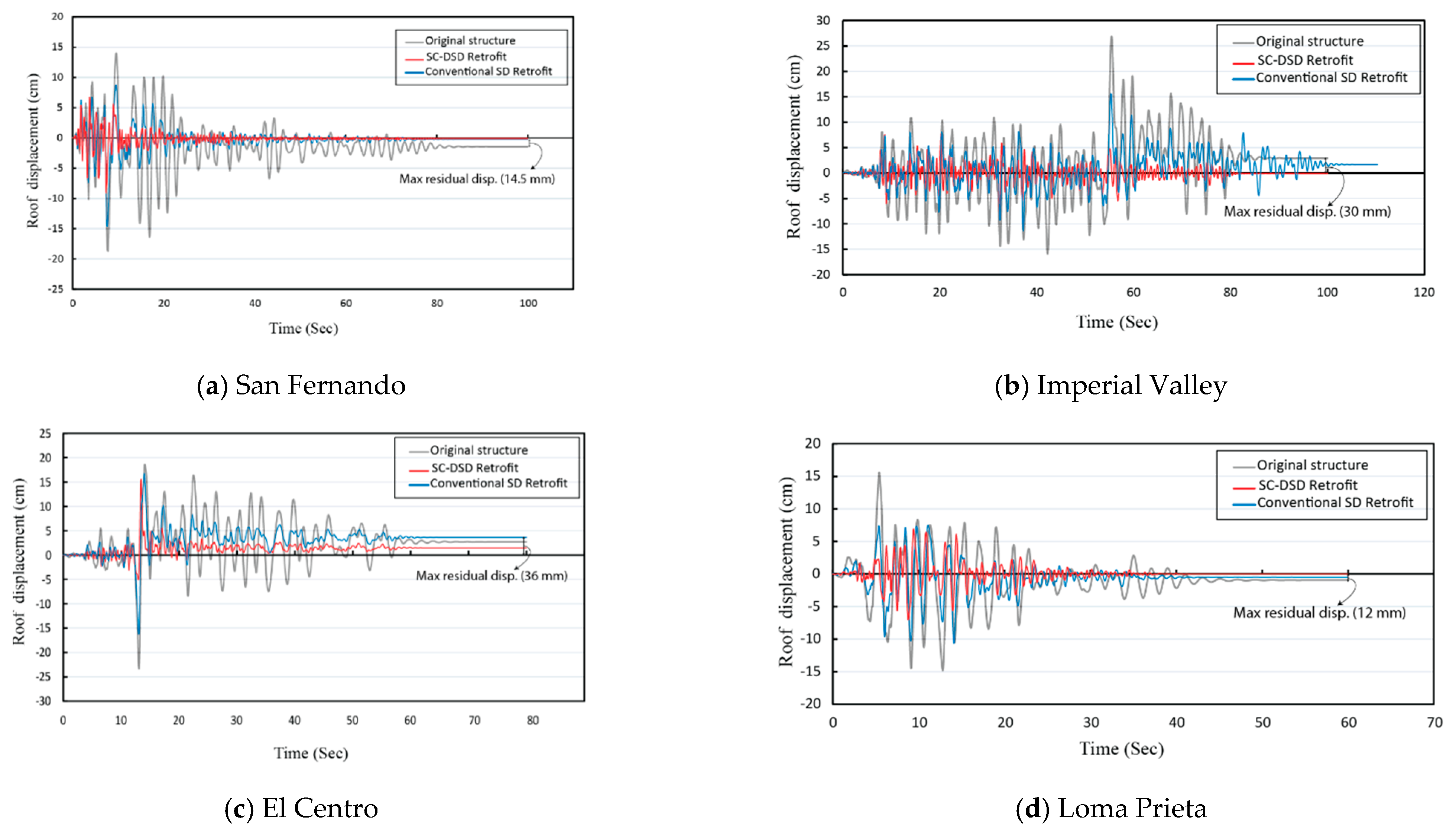
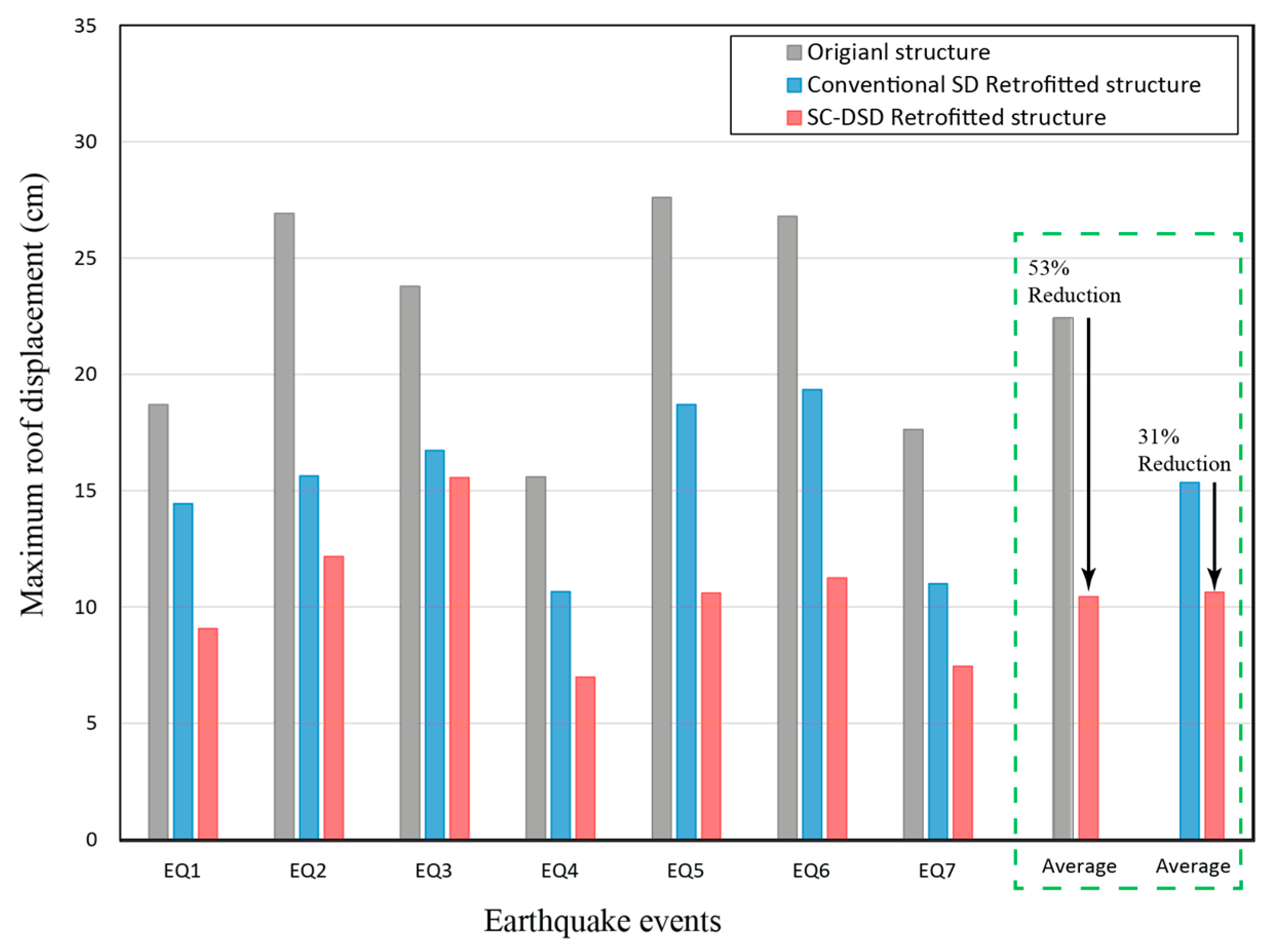
  • Analysis of displacement time histories highlighted the SC-DSD’s ability to reduce maximum displacement by up to 31% and eliminate permanent residual deformations compared to conventional SD retrofitted structures.
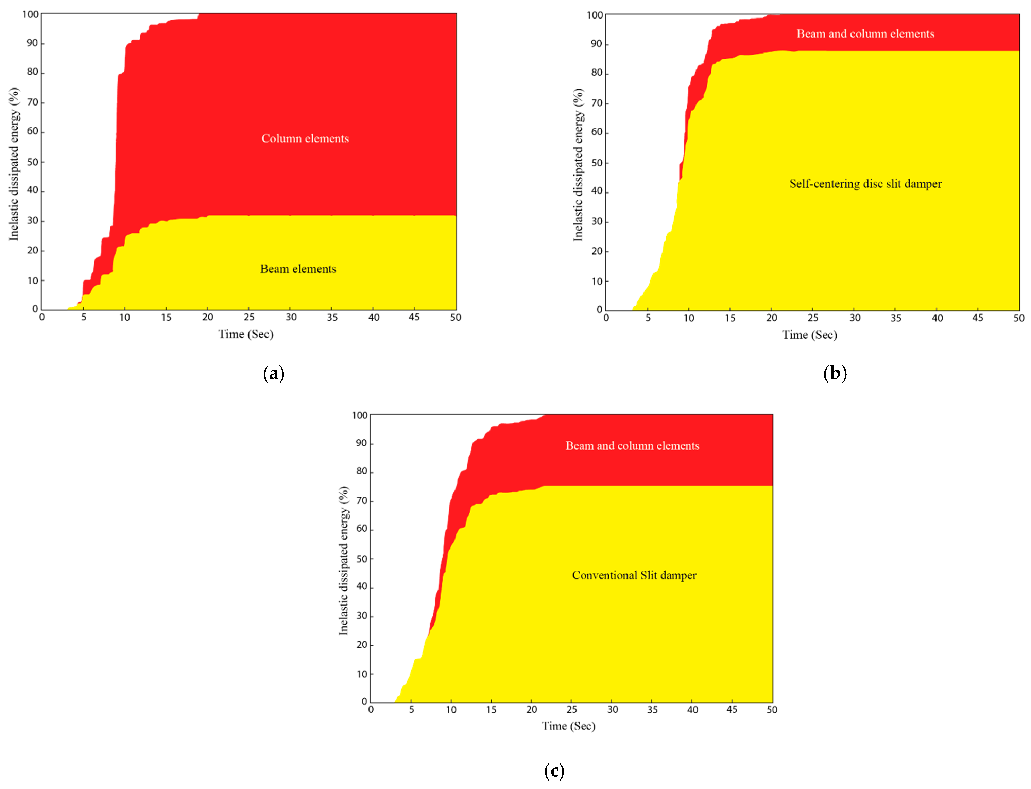
  • Time history analysis of hysteretic energy demonstrated that SC-DSDs effectively dissipated 80% of seismic-induced energy. At the same time, structural elements remained within the elastic range, meeting code requirements under design-level earthquake loads.
  • The design of the SC-DSD using performance point and equivalent damping ratio obtained through the capacity spectrum method proved to be an accurate approach for designing structures that incorporate this technology.
  • The SC-DSD system, with its lightweight design, compact size, and reusability, emerges as a cost-effective solution for enhancing the seismic performance of building structures through retrofitting.
Future studies could explore optimization strategies for SC-DSD design parameters and investigate their applicability across diverse structural typologies and seismic regions. Additionally, long-term monitoring of SC-DSD retrofitted structures in real-world scenarios would provide valuable insights into their performance and durability over time.

Author Contributions

Conceptualization, A.N.; methodology, J.L.; formal analysis, K.K.; investigation, A.N.; resources, J.L.; data curation, K.K.; writing—original draft, A.N. All authors have read and agreed to the published version of the manuscript.

Funding

This study was supported by ORIC and the Civil Engineering Department of UMT, Lahore, and the Earthquake Research Institute at The University of Tokyo, Japan. Additionally, it acknowledges funding from the National Research Foundation of Korea (NRF) through a grant funded by the Korean government (MSIT) (No. 2020R1C1C1005779).

Data Availability Statement

The data presented in this article can be obtained from the first author upon request.

Acknowledgments

The authors express gratitude to the Department of Civil Engineering, University of Management and Technology (UMT), Lahore, and the National Research Foundation of Korea (NRF) grant funded by the Korea government (MSIT) (No. 2020R1C1C1005779) for their invaluable support in conducting this research. Appreciation is also extended to the Earthquake Research Institute for their assistance during the experimental phase and data analysis.

Conflicts of Interest

The authors declare no conflicts of interest.

References

  1. Whittaker, A. Earthquake simulator testing of steel plate added damping. In Earthquake Engineering; University of California: Berkeley, CA, USA, 1989. [Google Scholar]
  2. Tsai, C.S.; Chen, K.C.; Chen, C.S. Seismic resistibility of high-rise buildings with combined velocity-dependent and velocity-independent devices. ASME-PUBLICATIONS-PVP 1998, 366, 103–110. [Google Scholar]
  3. Mualla, I.H.; Belev, B. Performance of steel frames with a new friction damper device under earthquake excitation. Eng. Struct. 2002, 24, 365–371. [Google Scholar] [CrossRef]
  4. Benavent-Climent, A. Seismic Design of Structures by Using Brace-Type Hysteretic Dampers; University of Tokyo (Japan): Tokyo, Japan, 1998. [Google Scholar]
  5. Benavent-Climent, A.; Morillas, L.; Vico, J.M. A study on using wide-flange section web under out-of-plane flexure for passive energy dissipation. Earthq. Eng. Struct. Dyn. 2011, 40, 473–490. [Google Scholar] [CrossRef]
  6. Sheikh, H.; Van Engelen, N.C.; Ruparathna, R. A review of base isolation systems with adaptive characteristics. In Structures; Elsevier: Amsterdam, The Netherlands, 2022; Volume 38, pp. 1542–1555. [Google Scholar]
  7. Kim, J.; Choi, H. Behavior and design of structures with buckling-restrained braces. Eng. Struct. 2004, 26, 693–706. [Google Scholar] [CrossRef]
  8. Yang, C.-S.W.; DesRoches, R.; Leon, R.T. Design and analysis of braced frames with shape memory alloy and energy-absorbing hybrid devices. Eng. Struct. 2010, 32, 498–507. [Google Scholar] [CrossRef]
  9. Darani, F.M.; Sahami, K.; Zarnani, P.; Veismoradi, S.; Bagheri, H.; Quenneville, P.; Haemmerle, E. Rocking Concrete Shear Walls with Self-Centring Friction Dampers for Seismic Protection of Building Structures. Available online: https://data.smar-conferences.org/SMAR_2019_Proceedings/Inhalt/we.3.b.4.pdf (accessed on 17 February 2024).
  10. Naeem, A.; Kim, J. Seismic retrofit of a framed structure using damped cable systems. Steel Compos. Struct. 2018, 29, 287–299. [Google Scholar]
  11. Naeem, A.; Eldin, M.N.; Kim, J.; Kim, J. Seismic performance evaluation of a structure retrofitted using steel slit dampers with shape memory alloy bars. Int. J. Steel Struct. 2017, 17, 1627–1638. [Google Scholar] [CrossRef]
  12. Naeem, A.; Kim, J. Seismic performance evaluation of a spring viscous damper cable system. Eng. Struct. 2018, 176, 455–467. [Google Scholar] [CrossRef]
  13. Naeem, A.; Kim, J. Seismic retrofit of 3000 kVA power transformer using friction dampers and prestressed tendons. Structures 2021, 32, 641–650. [Google Scholar] [CrossRef]
  14. Golzar, F.G.; Rodgers, G.W.; Chase, J.G. Design and experimental validation of a re-centring viscous dissipater. Structures 2018, 13, 193–200. [Google Scholar] [CrossRef]
  15. Rodgers, G.W.; Mander, J.B.; Chase, J.G.; Dhakal, R.P. Beyond ductility: Parametric testing of a jointed rocking beam-column connection designed for damage avoidance. J. Struct. Eng. 2016, 142, C4015006. [Google Scholar] [CrossRef]
  16. Chi, P.; Guo, T.; Peng, Y.; Cao, D.; Dong, J. Development of a self-centering tension-only brace for seismic protection of frame structures. Steel Compos. Struct. 2018, 26, 573–582. [Google Scholar]
  17. Shu, Z.; Li, Z.; He, M.; Zheng, X.; Wu, T. Seismic design and performance evaluation of self-centering timber moment resisting frames. Soil Dyn. Earthq. Eng. 2019, 119, 346–357. [Google Scholar] [CrossRef]
  18. Guan, X.; Burton, H.; Moradi, S. Seismic performance of a self-centering steel moment frame building: From component-level modeling to economic loss assessment. J. Constr. Steel Res. 2018, 150, 129–140. [Google Scholar] [CrossRef]
  19. Chan, R.W.; Albermani, F. Experimental study of steel slit damper for passive energy dissipation. Eng. Struct. 2008, 30, 1058–1066. [Google Scholar] [CrossRef]
  20. Naeem, A.; Kim, J. Seismic performance evaluation of a multi-slit damper. Eng. Struct. 2019, 189, 332–346. [Google Scholar] [CrossRef]
  21. Javidan, M.M.; Nasab, M.S.; Kim, J. Full-scale tests of two-story RC frames retrofitted with steel plate multi-slit dampers. Steel Compos. Struct. 2021, 39, 645–664. [Google Scholar]
  22. Lee, J.; Kim, J. Seismic performance evaluation of moment frames with slit-friction hybrid dampers. Earthq. Struct. 2015, 9, 1291–1311. [Google Scholar] [CrossRef]
  23. Lee, J.; Kim, J. Development of box-shaped steel slit dampers for seismic retrofit of building structures. Eng. Struct. 2017, 150, 934–946. [Google Scholar] [CrossRef]
  24. Wang, W.; Fang, C.; Shen, D.; Zhang, R.; Ding, J.; Wu, H. Performance assessment of disc spring-based self-centering braces for seismic hazard mitigation. Eng. Struct. 2021, 242, 112527. [Google Scholar] [CrossRef]
  25. Fang, C.; Wang, W.; Shen, D. Development and experimental study of disc spring–based self-centering devices for seismic resilience. J. Struct. Eng. 2021, 147, 04021094. [Google Scholar] [CrossRef]
  26. Zarnani, P.; Quenneville, P. A Resilient Slip Friction Joint; NZ IP Office: Wellington, New Zealand, 2015.
  27. Darani, F.M.; Zarnani, P.; Veismoradi, S.; Yousef-Beik, S.M.M.; Hashemi, A.; Quenneville, P. Resilient slip friction joint performance: Component analysis, spring model and anti-locking mechanism. Structures 2021, 33, 3897–3911. [Google Scholar] [CrossRef]
  28. Xu, L.; Fan, X.; Li, Z. Cyclic behavior and failure mechanism of self-centering energy dissipation braces with pre-pressed combination disc springs. Earthq. Eng. Struct. Dyn. 2017, 46, 1065–1080. [Google Scholar] [CrossRef]
  29. Jafari, A.; Sadeghi, M.; Alaee, F.J.; Bengar, H.A. Determining the optimal layout of energy-dissipating mechanisms for hybrid self-centering walls. Structures 2024, 60, 105854. [Google Scholar] [CrossRef]
  30. Naeem, A.; Maida, Y.; Koichi, K.; Javidan, M.M. Development and experimental verification of self-centering disc slit damper for buildings. J. Constr. Steel Res. 2023, 201, 107759. [Google Scholar] [CrossRef]
  31. Xu, L.; Fan, X.; Li, Z. Hysteretic analysis model for pre-pressed spring self-centering energy dissipation braces. J. Struct. Eng. 2018, 144, 04018073. [Google Scholar] [CrossRef]
  32. Ismail, M.; Ikhouane, F.; Rodellar, J. The hysteresis Bouc-Wen model, a survey. Arch. Comput. Methods Eng. 2009, 16, 161–188. [Google Scholar] [CrossRef]
  33. Soleimani, R.; Hamidi, H.; Khosravi, H. On advantages of the “Substitute Frame” model for incremental dynamic analysis: Integration of speed and accuracy. Structures 2022, 39, 266–277. [Google Scholar] [CrossRef]
  34. Usefi, N.; Sharafi, P.; Ronagh, H. Numerical models for lateral behaviour analysis of cold-formed steel framed walls: State of the art, evaluation and challenges. Thin Walled Struct. 2019, 138, 252–285. [Google Scholar] [CrossRef]
  35. FEMA. Prestandard, Interim Testing Protocols for Determining the Seismic Performance Characteristics of Structural and Nonstructural Components; (FEMA 461); Federal Energency Management Agency: Washington, DC, USA, 2007.
  36. American Society of Civil Engineers. Minimum Design Loads and Associated Criteria for Buildings and Other Structures, ASCE/SEI 7-22; American Society of Civil Engineers: Reston, VA, USA, 2022. [Google Scholar]
  37. ASCE/SEI Seismic Rehabilitation Standards Committee. Seismic Rehabilitation of Existing Buildings (ASCE/SEI 41-13); American Society of Civil Engineers: Reston, VA, USA, 2014. [Google Scholar]
  38. PERFORM. 3D User Manual (v8. 0.1). Computer and Structures. 2011. Available online: https://wiki.csiamerica.com/display/perform/Program+usage (accessed on 17 February 2024).
  39. ATC A. 40. Seismic Evaluation and Retrofit of Concrete Buildings; Applied Technology Council: Redwood City, CA, USA, 1996. [Google Scholar]
  40. PEER N. Database. Pacific Earthquake Engineering Research Center: NGA Database; University of California: Berkeley, CA, USA, 2007. [Google Scholar]
  41. Chopra, A.K. Dynamics of Structures; Pearson Education: London, UK, 2007. [Google Scholar]
Figure 1. The assembly process of SC-DSD with its different components.
Buildings 14 00795 g001
Figure 2. Details dimensions of slit damper and disc spring components.
Buildings 14 00795 g002
Figure 3. Numerical model of the proposed damper and its components.
Buildings 14 00795 g003
Figure 4. Experimental test: (a) Flag-shaped hysteresis of the prototype; (b) Steel strips of the slit damper in the prototype exhibited deformation [30].
Buildings 14 00795 g004
Figure 5. Structural plan and side elevation of the archetype school building.
Buildings 14 00795 g005
Figure 6. Nonlinear constitutive behavior of structural materials: (a) Concrete; (b) Reinforcement bars.
Buildings 14 00795 g006
Figure 7. Hysteresis characteristics of RC beams and columns: (a) Column analysis; (b) Beam analysis.
Buildings 14 00795 g007
Figure 8. Pushover analysis response of the case study frame structure.
Buildings 14 00795 g008
Figure 9. Derivation of hysteresis energy dissipated by the SC-DSD in each cycle.
Buildings 14 00795 g009
Figure 10. Location and connection details of dampers with a diagonal brace in the retrofitted structure.
Buildings 14 00795 g010
Figure 11. DBE level target spectrum according to ASCE 7-13 and SRSS spectra of selected ground motions.
Buildings 14 00795 g011
Figure 12. Inter-story drift ratios of the model structure before and after the seismic retrofit. (a) Original structure before retrofit. (b) Structure retrofitted with SC-DSD. (c) Structure retrofitted with conventional SD.
Buildings 14 00795 g012
Figure 13. Comparison between maximum inter-story drift ratios of the original structure and the retrofitted structures. (a) Original structure and structure retrofitted with SC-DSD. (b) Structure retrofitted with SC-DSD and conventional retrofitted SD.
Buildings 14 00795 g013
Figure 14. Roof displacement time history of the model structure with and without dampers under the selected ground motions.
Buildings 14 00795 g014aBuildings 14 00795 g014b
Figure 15. Comparison of maximum roof displacements of the bare structure, SC-DSD retrofitted structure, and conventional SD retrofitted structure.
Buildings 14 00795 g015
Figure 16. Maximum floor accelerations during excitation of the structure before and after the retrofit.
Buildings 14 00795 g016
Figure 17. Seismic energy dissipated in structural components and dampers. (a) Original structure. (b) Structure retrofitted with SC-DSD. (c) Structure retrofitted with conventional SD.
Buildings 14 00795 g017
Table 1. Characteristics of the slit damper and disc spring used in the prototype.
PropertiesSteel Slit DamperPropertiesDisc Springs
MaterialJISG-3446MaterialJIS-SUP-10
Elastic Modulus (GPa)220Elastic Modulus (GPa)200
Yield Strength (MPa)400Yield Strength (MPa)350
SectionHSS 200 × 200 × 12Section125–64 (125 mm outer dia and 64 mm inner dia)
Thickness (t) x width (b) of steel strip (mm)10 × 10Thickness of disc (mm)8
No. of steel strips8/side (total 32)Prestress load (kN)64
Length of steel strip (mm)100Configuration of disc springs2 Parallel disc springs
combined 8 in series
Stoke (mm)30Flatness load (kN)270
Stoke (mm)30
Table 2. Properties of beam cross-sections and reinforcement specifications.
StoryBeam Cross-Section Size (mm)Rebar Reinforcements
Ends (I, J)Mid Span
BottomTopBottomTop
1-2B-1300 × 5402-D196-#195-#192-#19
1-2B-2300 × 5602-D198-#196-#192-#19
1-2B-3300 × 5202-D197-#193-#192-#19
3-6B-1300 × 4502-D195-#195-#192-#19
3-6B-2300 × 4502-D198-#197-#192-#19
3-6B-3300 × 4303-D198-#195-#192-#19
Table 3. Properties of column cross-sections and reinforcement specifications.
Story and (Column Section)Cross-Section Size (mm)Rebar
1 (C-1)450 × 4508-#19
2~4 (C-1)400 × 4008-#19
5~6 (C-1)350 × 3508-#19
1 (C-2)650 × 65016-#19
2~4 (C-2)600 × 60012-#19
5~6 (C-2)550 × 55016-#19
1 (C-3)500 × 50012-#19
2~4 (C-3)450 × 4508-#19
5~6 (C-3)450 × 45016-#19
Table 4. Details of seven earthquake records used for the seismic evaluation.
EQ
Serial No.
Record No. in PEEREarthquake NameStation
Component
PGA Max. (g)Magnitude
(Mw)
SFRrup (km)Vs30 (m/s)Lowest Usable Freq. (Hz)
EQ 168San FernandoSFERN/PEL1800.236.612.122.7316.460.1
EQ 2174Imperial ValleyIMPVALL/H-Ell2300.396.531.212.5196.250.1
EQ 3721El CentroSUPERST/B-ICC0000.366.541.318.2192.060.08
EQ 4752Loma PrietaLOMAP/CAP0000.536.911.58.56288.620.25
EQ 5953NorthridgeNORTHR/MUL0090.526.731.19.44355.810.15
EQ 61111Kobe JapanKOBE/MIS0000.516.901.27.08609.00.12
EQ 71485Chi-ChiCHICHI/CHY101-E0.447.621.326.0704.640.05
Disclaimer/Publisher’s Note: The statements, opinions and data contained in all publications are solely those of the individual author(s) and contributor(s) and not of MDPI and/or the editor(s). MDPI and/or the editor(s) disclaim responsibility for any injury to people or property resulting from any ideas, methods, instructions or products referred to in the content.

