Article

Mechanical Properties and Hydration Mechanism of Iron Tailings–Cement-Based Supplementary Cementitious Materials

1
School of Resources and Civil Engineering, Northeastern University, Shenyang 110819, China
2
Science and Technology Innovation Center of Smart Water and Resource Environment, Northeastern University, Shenyang 110819, China
3
Liaoning Institute of Technological Innovation in Solid Waste Utilization, Shenyang 110819, China
4
School of Architecture and Civil Engineering, Shenyang University of Technology, Shenyang 110870, China
*
Author to whom correspondence should be addressed.
Buildings 2024, 14(4), 1044; https://doi.org/10.3390/buildings14041044
Submission received: 26 January 2024 / Revised: 9 February 2024 / Accepted: 18 March 2024 / Published: 8 April 2024
(This article belongs to the Section Building Materials, and Repair & Renovation)

Abstract

:
The preparation of cement-based supplementary cementitious materials is an important method for the efficient use of iron tailings and the reduction in CO2 emissions. The aim of this study is to improve the reactivity of iron tailings by mixing them with steel slag, slag, and fly ash through orthogonal tests to solve the problem that iron tailings cannot be utilised on a large scale. The compressive strength, hydration products, and microstructure of the iron tailings–cement-based supplementary cementitious materials were investigated using ICP-OES, XRD, TG, FTIR, and SEM. The results revealed that each solid waste raw material played a distinct role in the hydration reaction. In the iron tailings–cement-based supplementary cementitious materials system, steel slag provided Ca2+, OH, and Si4+ ions, slag provided Ca2+ and Al3+ ions, fly ash contributed a significant amount of Ca2+ and Al3+ ions, and iron tailings offered more nucleation sites and some Si4+ ions for the hydration products. Moreover, there was a synergistic effect among these four materials, promoting the formation of hydration products such as ettringite, C-(A)-S-H gels, and others. When the proportion of IOTs:SS:FA:SL was 9:8:8:2, the highest 7 d compressive strength of cementitious material was 24.8 MPa. When the proportion of IOTs:SS:FA:SL was 9:6:8:4, the highest 28 d compressive strength of cementitious material was 35.0 MPa. This study provides a comprehensive solution for the utilisation of iron tailings and contributes to the high-value green utilisation of solid waste.

1. Introduction

Iron tailings (IOTs) are waste residue with the dual characteristics of secondary resources and environmental pollution produced after ore dressing, which is the main component of industrial solid waste [1,2,3,4]. Data show that China’s existing IOT stockpile has exceeded 5 billion tonnes, and the annual emissions of new IOTs are nearly 300 million tonnes, but the comprehensive utilisation rate of IOTs is only 27.69% [5]. Therefore, in recent years, the recycling of IOTs has gradually received attention, and more and more treatment methods have been proposed [6,7]. As some of the physicochemical properties of IOTs themselves are very comparable to those of current cement-based building materials, the utilisation of IOTs for construction materials is already one of the common ways of utilizing IOT resources, which mainly includes the production of cement and concrete, road construction materials, and building bricks, as well as high-value construction products such as microcrystalline glass, foam ceramics. and aerated concrete [8,9,10]. However, the current research mainly focuses on IOT waste rock as concrete aggregate, which largely reduces the admixture of IOTs in concrete, limiting the application value of ultrafine IOTs, while powdered IOTs are more likely to cause dust and other environmental problems [11,12,13,14]. Therefore, in order to make full use of ultrafine IOTs and produce high value-added products, IOTs can be developed as supplementary cementitious materials (SCMs) for concrete, which further reduces the cost of producing both cement and concrete products, and achieves the purpose of multi-functionality between the utilisation of solid waste resources and the green production of concrete products [15,16,17]. While it is feasible to add small amounts of IOTs to cementitious supplementary cementitious materials, this may not fulfil the original purpose of researching SCMs, which were actually developed and applied to reduce clinker usage and hence carbon emissions from cementitious materials [18,19]. However, about 10 per cent of current IOTs have such little impact on mechanical properties that the environmental benefits of doing so are negligible [20]. In order to solve the above problems, Zhang et al. proposed the idea of using IOTs to prepare composite SCMs, which consist of IOTs and other solid waste materials. It is worth mentioning that the composite SCM also provides a recycling channel for other solid wastes [21,22].
Steel slag (SS) is a by-product of the steel industry and accounts for approximately 10–15% of crude steel production [23,24]. Unlike blast furnace slag and fly ash, steel slag is not commonly used in the manufacturing of cement supplementary cementitious materials. One of the main factors contributing to this is its elevated concentration of free radicals, such as calcium oxide and magnesium oxide, which can cause the expansion of cement paste [25]. Consequently, the utilisation rate of steel slag in China is relatively low, resulting in significant stockpiling and subsequent land occupation and environmental pollution [26]. To address the environmental issues associated with the stockpiling of SS, a solution has been proposed involving the use of flue gas desulphurisation gypsum and fly ash as the foundation for the development of green cementitious materials. By incorporating steel slag or slag into this system, the results have shown that different mineral additives have a beneficial impact on the system when used in appropriate dosages [27]. In a study by Zhou regarding fly ash–steel slag binary composite cementitious materials, it was discovered that the addition of fly ash can mitigate the detrimental effects caused by the expansion of steel slag, enhance the material’s macrostructure, and improve system stability [28].
Fly ash (FA), as an industrial solid waste from power plants, is widely used to improve the volume stability, durability, workability, and other basic properties of cementitious materials because of its smooth surface [29,30]. However, current research has shown that the compressive strength of the cement–fly ash (P-FA) system is low, especially when the FA admixture is above 50% of the total mass of concrete [31]. In general, the use of FA in supplementary cementitious materials is not recommended to exceed 30%, and once it exceeds 30%, the macroscopic properties of the material will be negatively affected [32]. Therefore, the problem of the low incorporation of FA cementitious materials should be addressed first. From existing studies [33,34,35], it can be seen that the synergistic effect between different industrial waste constituents results in composite cementitious materials with good mechanical properties. In general, this synergy is caused by two main aspects: firstly, by the complementary nature of the chemical elements (e.g., Al-Ca and Si-Ca) in the different feedstocks, and secondly, the particle morphology of different raw materials and the roughness of the particle surface affect the pore structure of the system, which in turn affects the macroscopic properties. Therefore, most of the current studies have selected solid waste raw materials with synergistic effects for use in auxiliary cementitious material compound preparation.
Multiple solid waste composite supplementary cementitious materials involve the use of two or more types of industrial solid waste together as raw materials for the preparation of cementitious materials [36,37,38]. As a result of the growing construction industry, the requirements for concrete performance have gradually become higher, and single-mineral cementitious materials are gradually failing to meet the requirements for the mechanical and working properties of concrete [39,40]. Therefore, it is imperative to research and develop new cement-based supplementary cementitious materials to meet the needs of the concrete industry, increase the amount of cementitious materials, and reduce CO2 emissions from the concrete industry [41,42,43]. Industrial solid wastes of different natures can produce optimal complementary advantages during hydration reactions and structure formation in different systems [44,45]. Therefore, it is important to study the synergistic effect and hydration between solid wastes, which can provide a theoretical basis for their effective utilisation [46,47]. The low volcanic ash activity of materials such as SS and IOTs is one of the main constraints to their resource utilisation. Although there is a synergistic effect among SS, IOTs, SL, and FA during the hydration reaction, the reaction mechanisms and product structures among them have not been reported in previous studies [48]. In this research, multi-faceted solid waste-assisted cementitious materials with IOTs as the siliceous raw material, SS and SL as the calcareous raw material, and FA as the aluminium raw material were prepared and characterised by inductively coupled plasma emission spectroscopy (ICP-OES) for ion leaching behaviour. The mechanical properties of the mortar were analysed based on its compressive strength. The hydration products were characterised by XRD, SEM, FTIR, and TG. The synergistic effect between solid waste materials in the cement-based supplementary cementitious material system was studied. A flow chart describing the research methodology is shown in Figure 1.

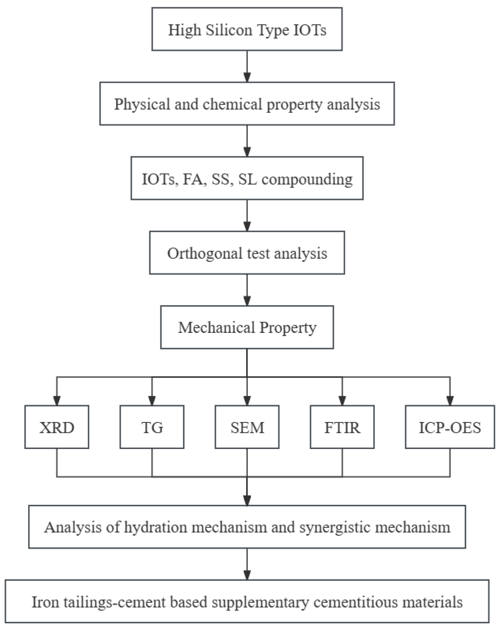
2. Materials and Methods

2.1. Materials

Ordinary Portland cement (P·O 42.5) was employed in this test. IOTs, SS, FA, and GBFS were used as SCMs. It should be noted that the GBFS used is a low-quality slag, which is S95 grade GBFS, as specified in GB/T 18046-2008 [49]. As can be seen from Table 1, the IOTs used in this study have a high silica content and are high-silica-type iron tailings. Figure 2 displays the X-ray diffraction patterns of the raw materials. The SiO2 in the IOTs exists as an α-quartz phase, which is a very stable crystal and has a hardness of up to 7 [50,51]. This corresponds to two typical characteristics of IOTs: low reactivity and difficult to grind. The C3S and C2S in SS makes it exhibit latent hydration properties [52]. Therefore, SS, FA, and GBFS all have higher activity in cementitious systems, especially in the later stages of hydration [53]. The granularity profiles of the raw materials are shown in Figure 3. Particle morphology of the raw materials by SEM are shown in Figure 4. Moreover, the specific surface area of the binders is listed in Table 1.

2.2. Preparation of Specimens

2.2.1. Preparation of Blend Mortar

Undoubtedly, adjusting the ratio of SS, FA, and GBFS can modify the properties of composite SCMs. However, the mixture design for three materials is difficult to achieve. Therefore, a three-factor, four-level orthogonal test design method was used in this study for composite SCMs, with a total of 96 blend mortar specimens. Table 2 demonstrates the actual amount of each material and the corresponding orthogonal test levels. IOTs and composite SCMs account for 10% and 20% of the total mass of the cementitious material, respectively. The steps for preparing the mortar using a planetary mortar mixer were as follows. The slurry was first added to the mixing pot. The machine was then controlled to mix at a slow speed of 140 rpm for 120 s and standard sand was added during the slow mixing process, followed by a fast continuation of mixing at 285 rpm for 90 s. The mixing ratio of glue material to sand during the preparation of the specimen samples in this study was 1:3, based on the Chinese standard (GB/T 12957-2005) [54]. After mixing was completed, vibration compaction was carried out, and subsequently, the slurry was placed in moulds of size 40 × 40 × 160 mm. After demoulding, the specimens were kept at a temperature of 20 °C and a humidity of 98%. The unconfined compressive strength tests were carried out when the specimens were cured for 7 and 28 d.

2.2.2. Preparation of Blend Paste

In order to study the hydration reaction mechanism of SCMs, XRD, TG, and FTIR tests were carried out. The specimens prepared in this part of the test should be the net mortar specimens without mixing with the standard sand, and the specimen preparation process is the same as in the previous test, the only difference being that the specimen size is 4 × 4 × 4 cm3. After specimen preparation, the specimens were maintained for a specified time period. The specimens should be processed before the test; firstly, the specimens were crushed, and then the crushed pieces were placed in isopropyl alcohol to terminate hydration, and finally, the specimens were dried and ground for further use in the test.

2.3. Test Procedure

2.3.1. Compressive Strength

The model of the machine used for the compressive strength test was TSY-2000A, and the loading speed set by the machine was 2.4 kN/s. After completion of the compressive test, the obtained data were processed, the data values with large errors were deleted, and the average of the three sets of data was taken as the final test result [54].

2.3.2. X-ray Diffraction

A test X-ray diffractometer was used to analyse the hydration products; the specimen samples used for the analytical tests had been soaked in isopropanol to terminate hydration for 6 h and dried and powdered. During the test, 2θ was set from 5° to 70° and the scanning speed was set at 10°/min increments of 0.02°.

2.3.3. Thermogravimetric Analysis

The sample preparation for thermogravimetry (TG) was the same as for XRD, i.e., termination of hydration followed by grinding into powder. A test interval of 30–1000 °C was selected for TG, with a heating rate of 20 °C/min. The test was performed at a constant ambient temperature and under a nitrogen atmosphere [55].

2.3.4. Fourier Transform Infrared

The tests were performed using a Nicolet iS20 Fourier Transform Infrared (FTIR) spectrometer manufactured by Thermo Scientific (Waltham, MA, USA), with selected wavelengths ranging from 400 cm−1 to 4000 cm−1. The samples used for the test were cooled to room temperature and ground before the start of the test. The specimens were cooled to room temperature before the start of the test and then milled. Upon completion of the detection test, the characteristic frequency and intensity of the infrared absorption peaks were used to determine the molecular structure and chemical composition of the test sample.

2.3.5. Scanning Electron Microscopy

The microstructure of the hydration products of the specimens was analysed and characterised by SEM, using a TESCAN MIRA LMS (Czech). The test samples were conditioned for 28 d and hydration was terminated. The samples were cleaned with an ultrasonic cleaner and dried at 40 °C prior to testing.

2.3.6. Inductively Coupled Plasma–Optical Emission Spectroscopy

In order to study the mechanism of the synergistic effect of the hydration reaction of specimen samples, the change in ion concentration of the specimen samples was analysed and studied using inductively coupled plasma emission spectroscopy (ICP-OES) in this study. The machine used for the tests was 5110 ICP-OES manufactured by Agllent Technologies (Shanghai) Co. (Shanghai, China).

3. Results

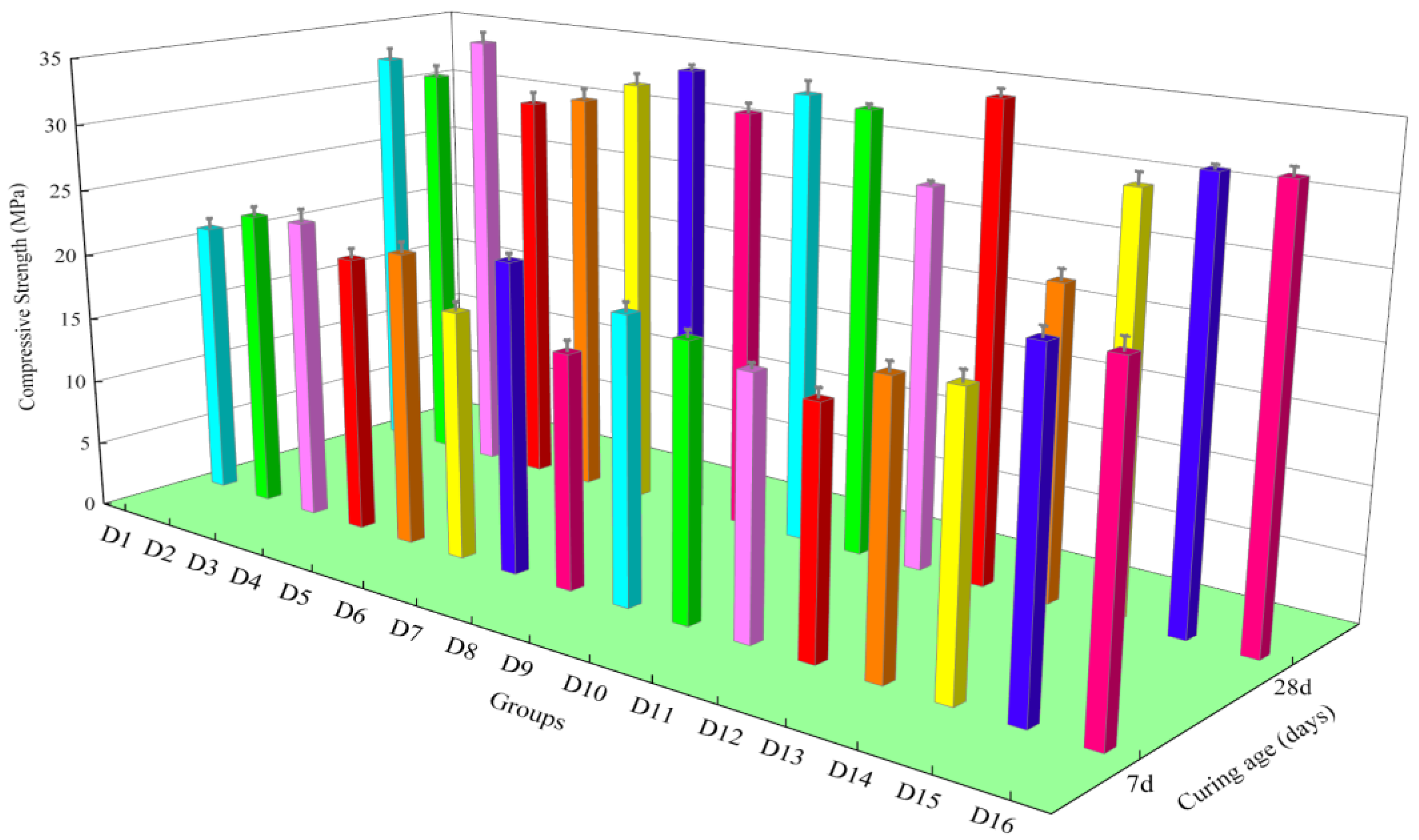
3.1. Mechanical Properties

The orthogonal test results for compressive strength are displayed in Table 3 and Table 4 and Figure 5. The orthogonal tests of mixtures presented complex results, but undoubtedly, D16 and D12 exhibited the highest compressive strengths at 7 d and 28 d, respectively. Due to the low quality of GBFS, changes in its incorporation did not significantly affect the compressive strength of IOT mortar. Figure 6 shows the flowability of mortar with different ratios, where the D8 flowability is 195 mm, which correlates with the amount of FA incorporated. Although FA possessed excellent filler and nucleation effects and its spherical morphology improved the workability of the mortar [56,57], FA was the weakest parameter for the 28 d strength development of IOT mortar among the three materials. The reason for this was that the degree of FA reaction at 28 d was still low, and numerous reports concluded that the contribution of FA to strength occurred mainly at a much later age. Conversely, the range analysis revealed that the effect of SS on the composite SCM system remained dominant regardless of age. An increase in the strength of SS and the IOT cement system was similarly observed. It was concluded that IOTs facilitated the reaction of the silicate in SS, while the dissolved components from IOTs continued to react with the calcium hydroxide derived from the hydration of SS to form more hydration products [21,22,58]. The synergistic effect between IOTs and SS significantly improved the 28 d compressive strength of IOT mortars. Nevertheless, the inhibition of early hydration by SS cannot be ignored, which resulted in a poor strength enhancement effect of composite SCMs with IOT mortar at 7 d. From the compressive strength test results, it can be seen that D12 and D16 are the optimal proportions of the composite SCMs, and thus, their hydration process was investigated.

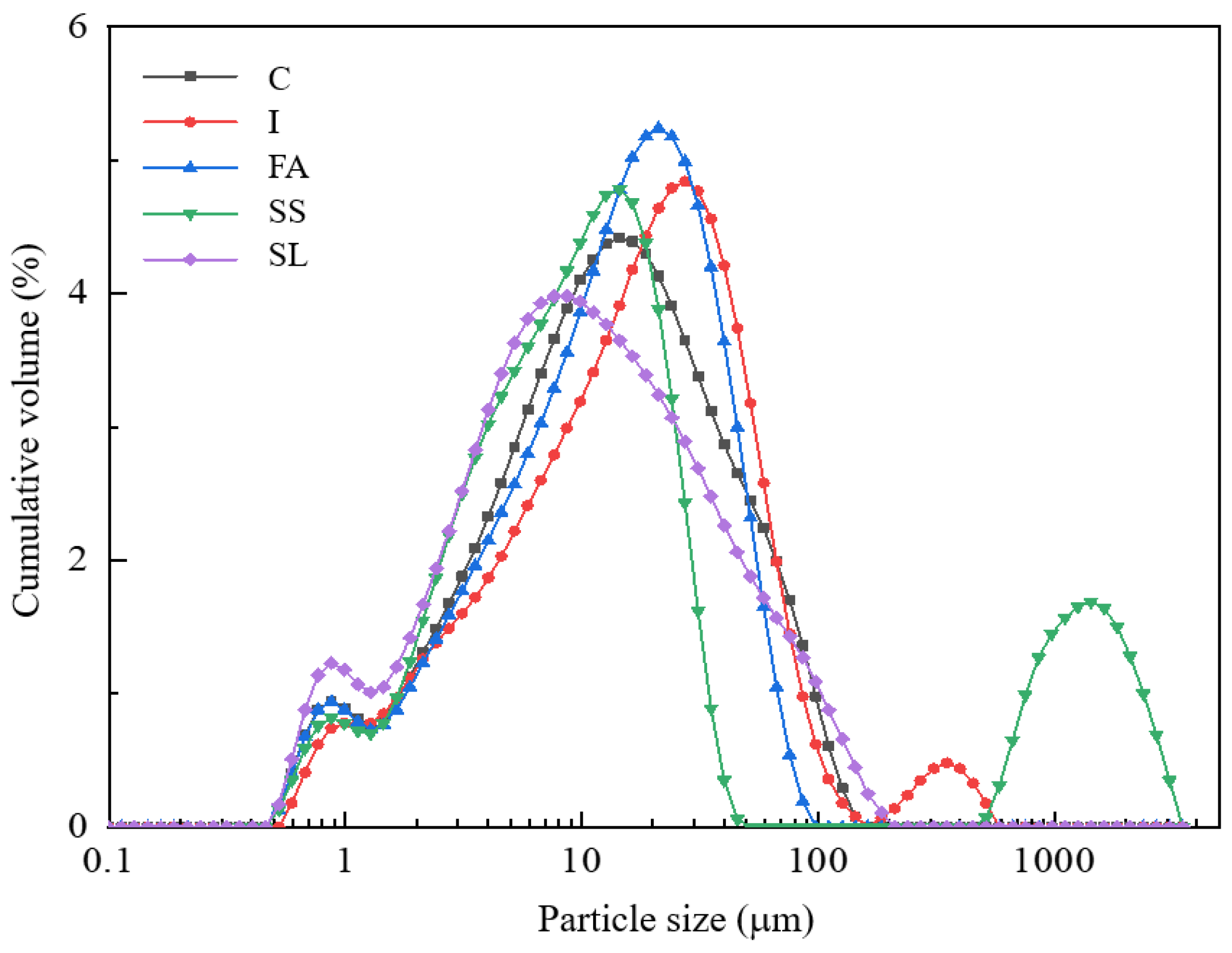
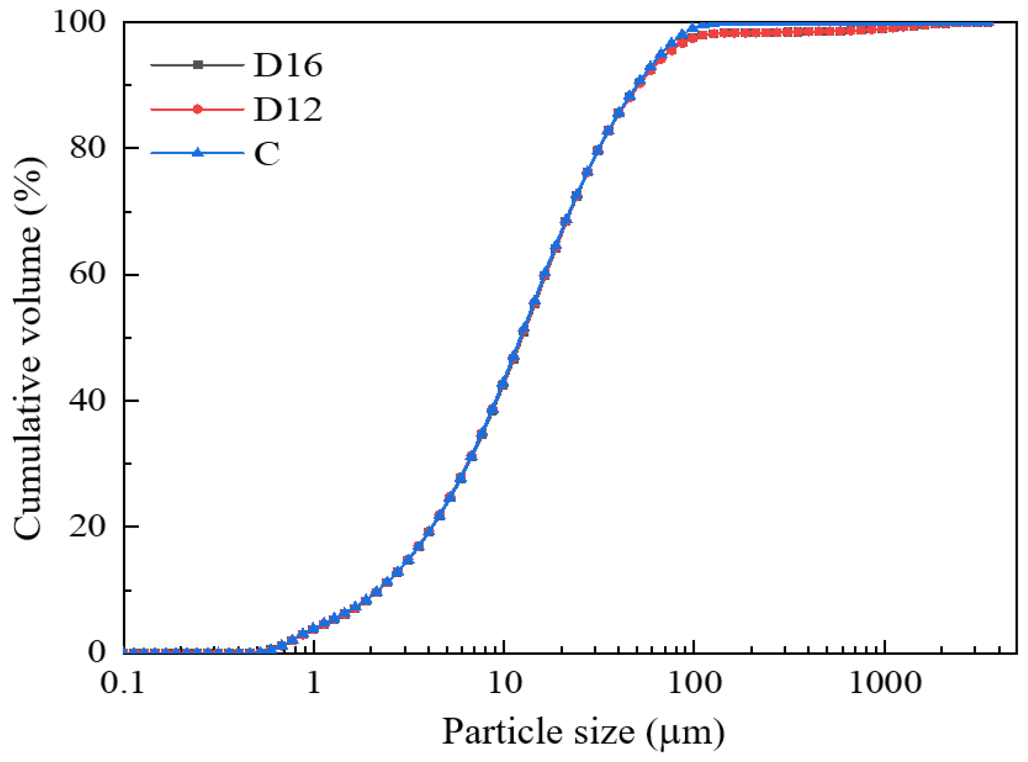
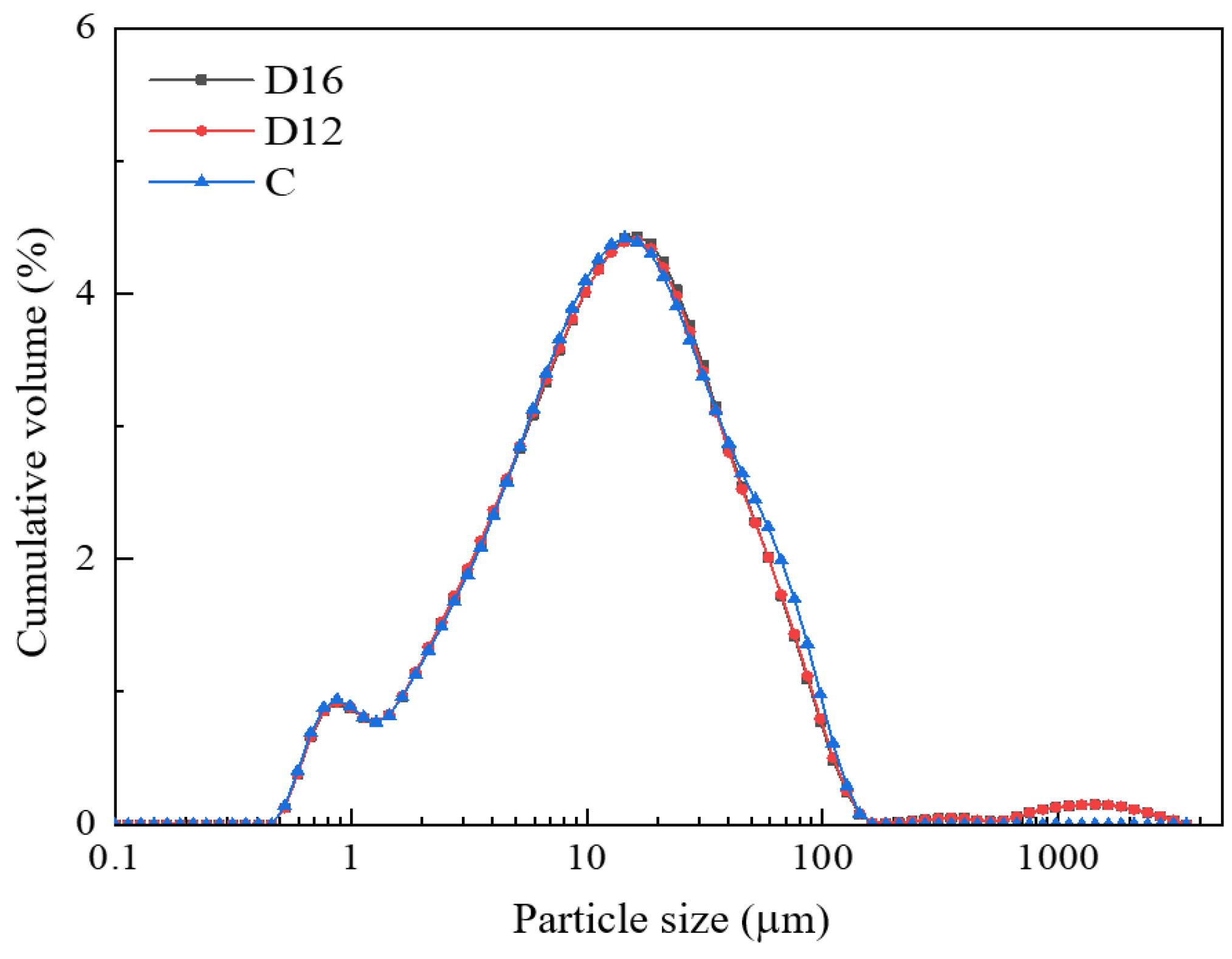
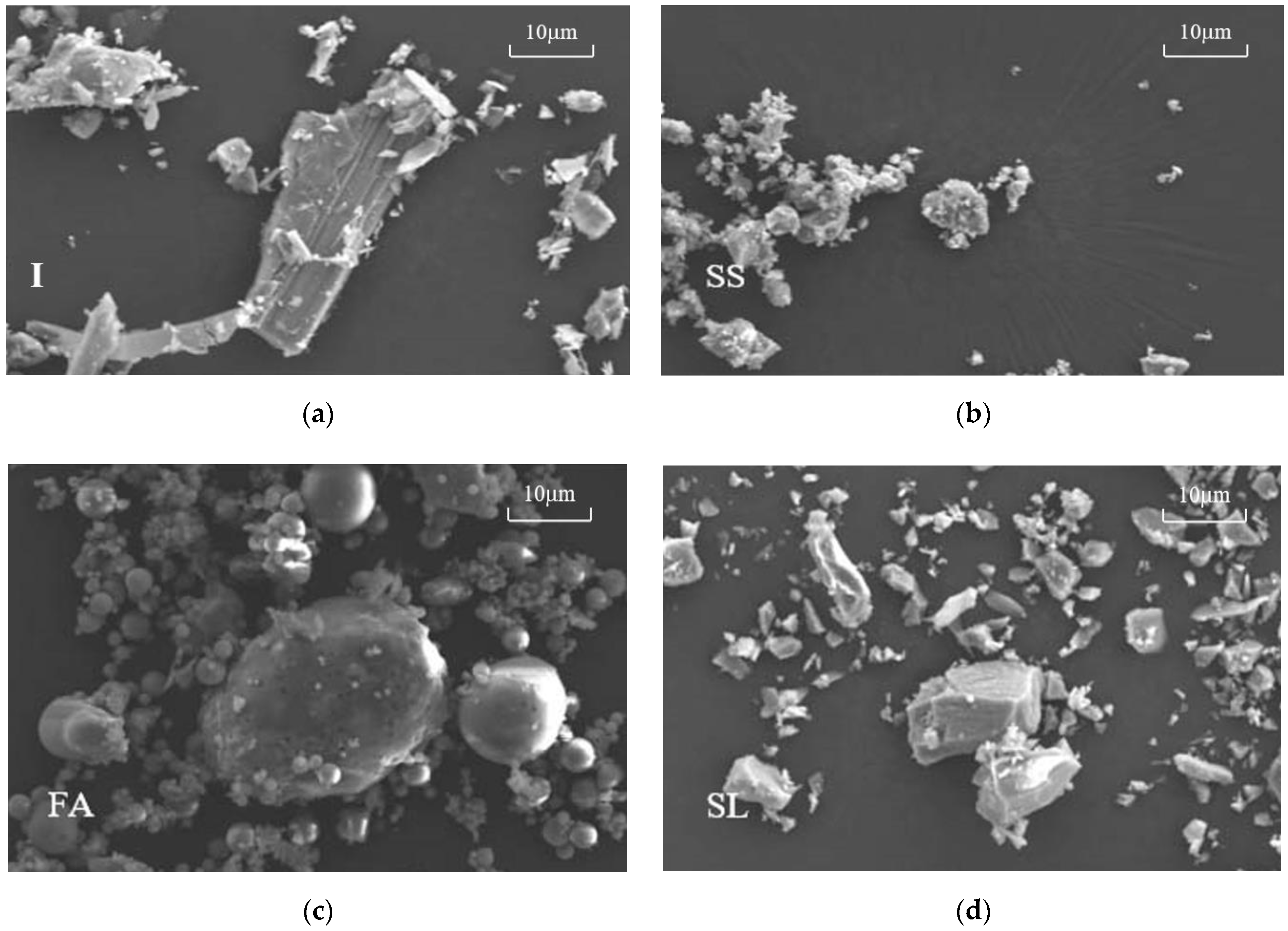
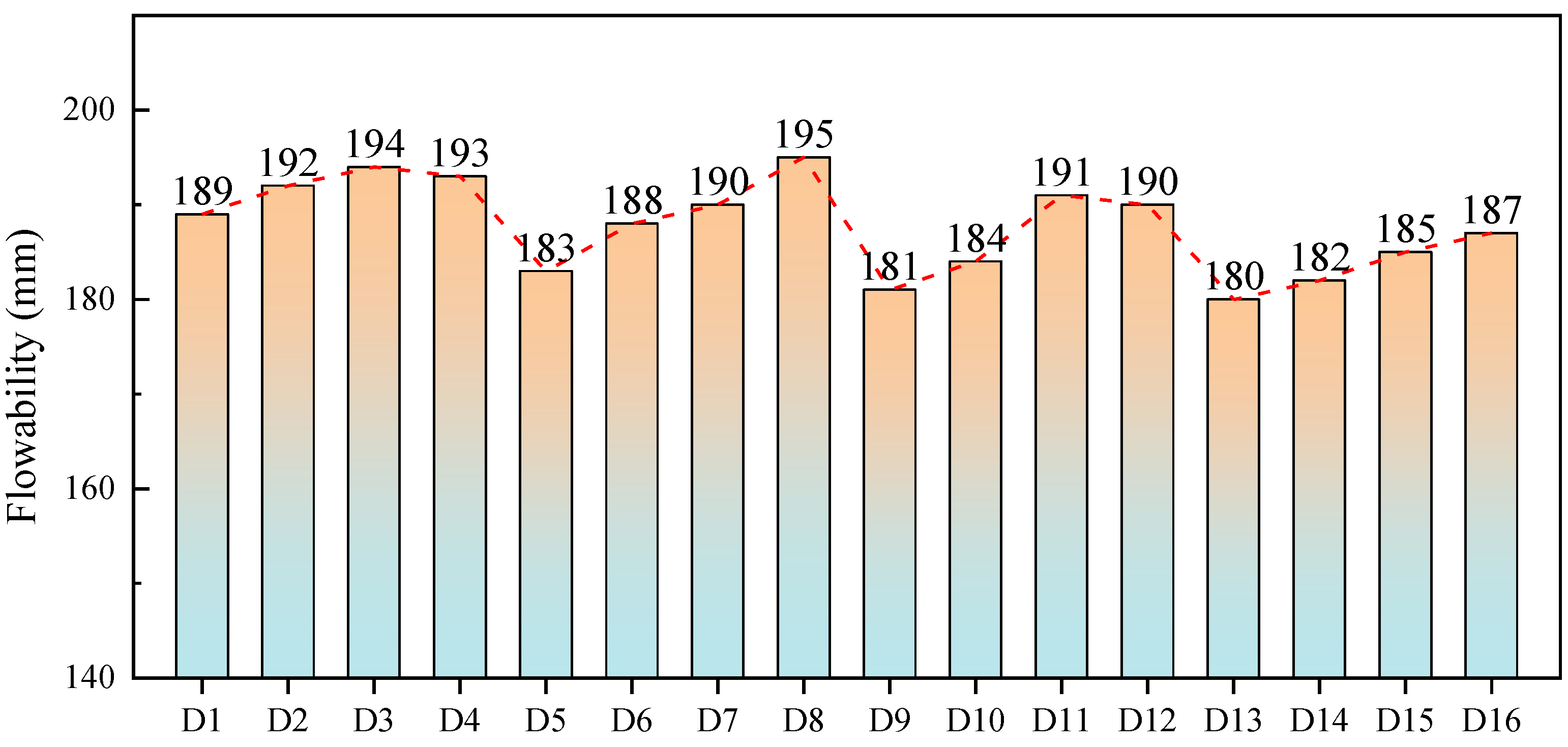
3.2. Particle Characteristic

The cumulative particle size distribution of iron tailings–cement-based supplementary cementitious materials is shown in Figure 7. The cumulative particle size distribution of the SCMs is almost consistent with the cumulative particle size distribution of pure cement, which to some extent eliminates the influence of changing the particle size distribution of the original cement after mixing with SCMs. As shown in the particle size distribution diagram of the SCMs in Figure 8, the particle size distribution of the SCMs is consistent with the cumulative particle size distribution pattern and remains around the particle size of pure cement. Unlike the particle size distribution of pure cement, the SCMs exhibit a particle size greater than 1000 μm, which may be caused by the presence of particles larger than 1000 μm in the steel slag [59].

3.3. Hydration Product-Type Test Results
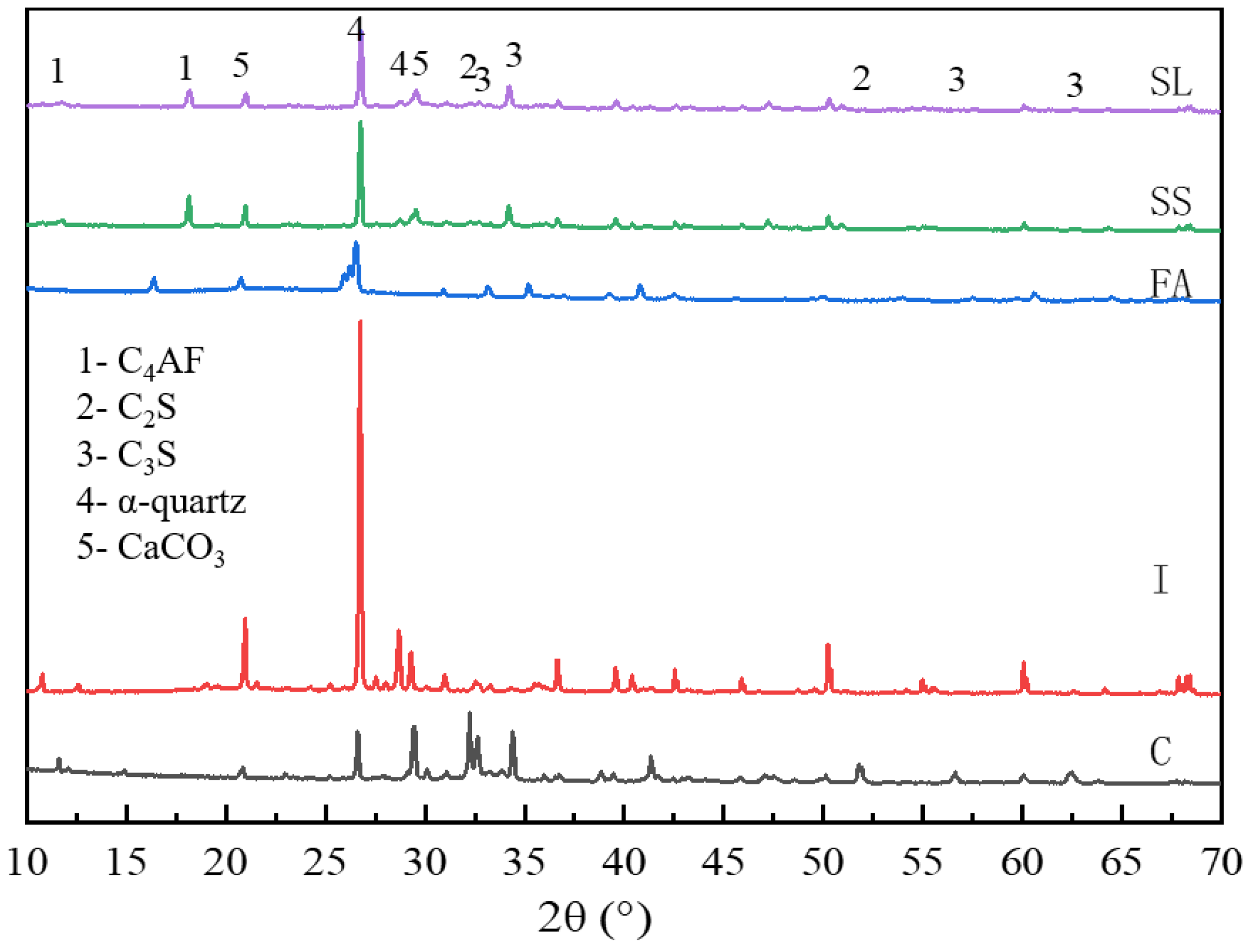
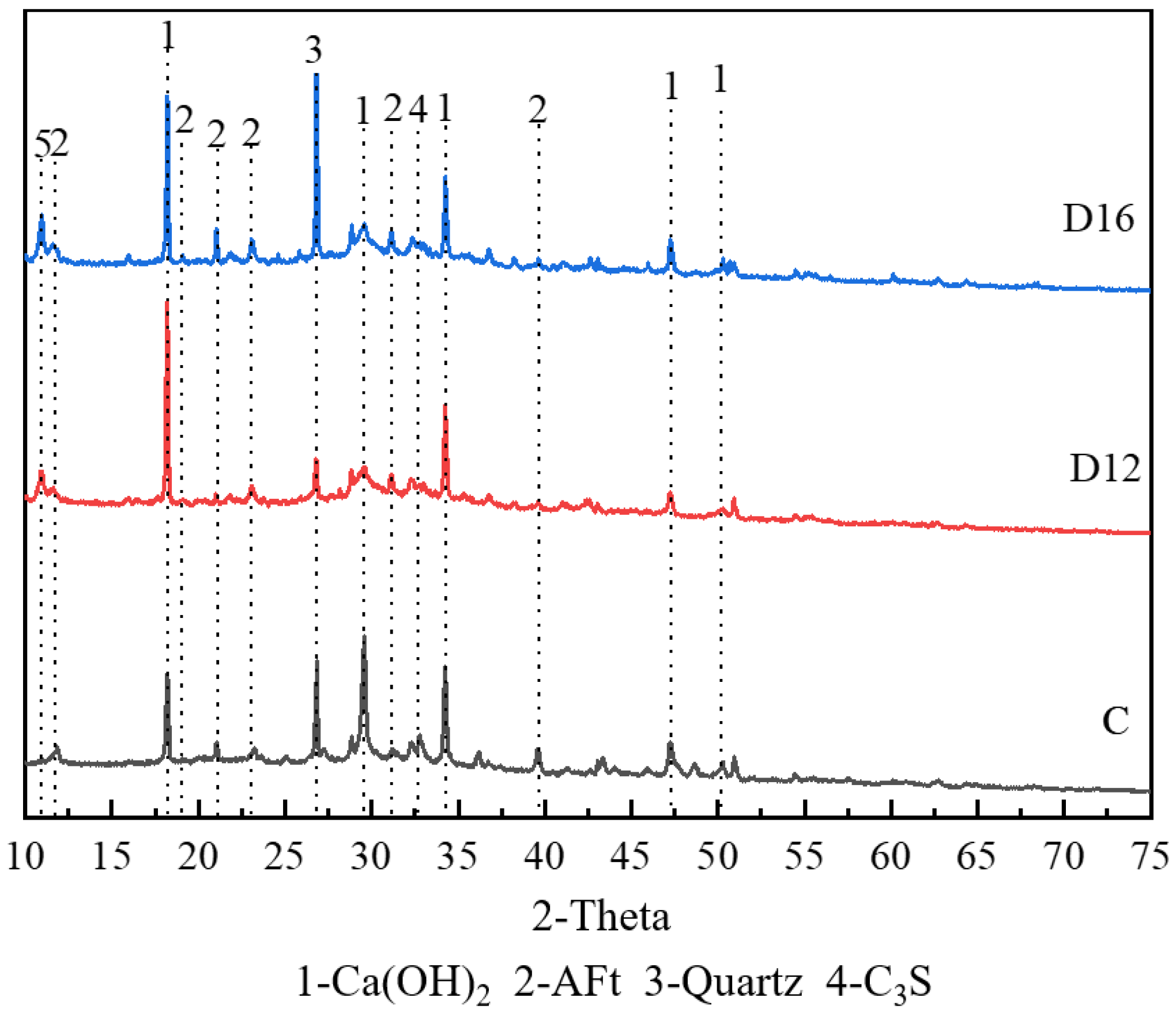
3.3.1. XRD Results

The XRD patterns of D12 and D16 are shown in Figure 9. The incorporation of the composite SCMs resulted in a distinct diffraction peak, and the intensity was stronger for D16. Studies have confirmed that the peak is the diffraction of hemicarboaluminate (Hc). Carboaluminate belongs to the AFm phase with two types of Hc and monocarboaluminate (Mc). The carboaluminate phase is one of the major hydration products in limestone cement systems such as LC3. The presence of Hc and Mc also implies that the sulphate in the monosulfoaluminate has been replaced by carbonate, while ettringite has been stabilised as a result. Accordingly, as the Hc content increased, there was a gradual growth of ettringite in IOT pastes, which contributed to the development of the strength and microstructure. It is worth noting that the formation of Hc requires the simultaneous presence of both carbonate and aluminate. In the composite SCMs, GBFS and FA provided aluminium, while calcium carbonate in SS contributed the extremely critical carbonate for Hc. Consequently, the D16 containing the most SS also exhibited the highest amount of Hc. Another hydration product with significant changes in content was calcium hydroxide. The calcium hydroxide content was higher in IOT pastes compared to cement. On the one hand, this indicates that the SCM including IOTs promoted the hydration of cement; on the other hand, the hydration of the calcium–silica phases in SS and GBFS was also a source of calcium hydroxide [21].

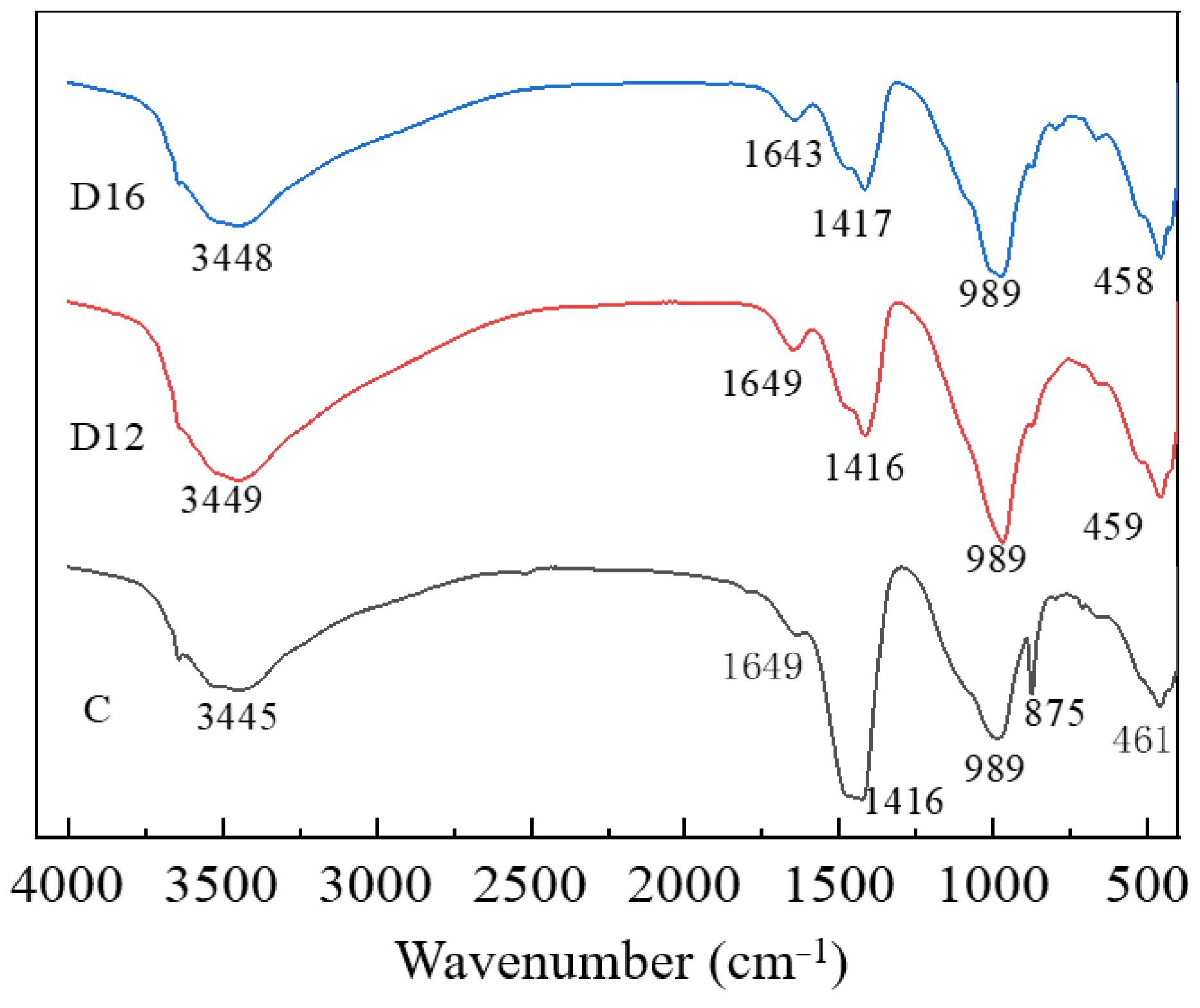
3.3.2. FTIR Spectroscopy Results

The FTIR spectroscopy of the iron tailings–cement-based supplementary cementitious materials is shown in Figure 10. It can be seen that the peak between 3445 cm−1 and 1649 cm−1 is the hydroxyl characteristic absorption band, which is caused by the stretching oscillations of the O-H moiety of the binding solution, corresponding to the ettringite and C-(A)-S-H gels produced due to hydration of the SCMs. The vibration peak generated at 1416 cm−1 is caused by the asymmetric stretching of C-O in CO32−, which is a carbonate formed by the contact between Ca(OH)2 in the SCMs and CO2 in the air. The peak at 989 cm−1 is produced by typical Si-O-T (T:Al, Si) asymmetric tensile vibration, corresponding to the hydrated C-(A)-S-H gel in the hydration product. The peak at 875 cm−1 corresponds to the asymmetric stretching of AlO4 groups in the Al-O-Si bond and to the characteristic band of the hydration product C-A-S-H gel. The absorption band at 461 cm−1 is induced by flexural vibrations in the Si-O-Si plane, and the corresponding hydrogel is a C-(A)-S-H gel [60].
The characteristic peaks of the three samples around 989 cm−1 and 459 cm−1 are Si-O-T (T: Al, Si) and Si-O-Si, respectively. The movement of the characteristic peaks of the C-(A)-S-H gel can reflect the degree of silica–oxygen tetrahedra polymerisation; the addition of the SCMs reduced the degree of silica–oxygen tetrahedra polymerisation in the hydration products, and the reduction in the degree of polymerisation was affected by the difference between the different solid waste doping ratios, i.e., the reduction in the SS:SL ratio increased the degree of polymerisation of silica–oxygen tetrahedra [22]. At 875 cm−1, the characteristic peaks of CO32− are obvious in both D12 and D16 samples.

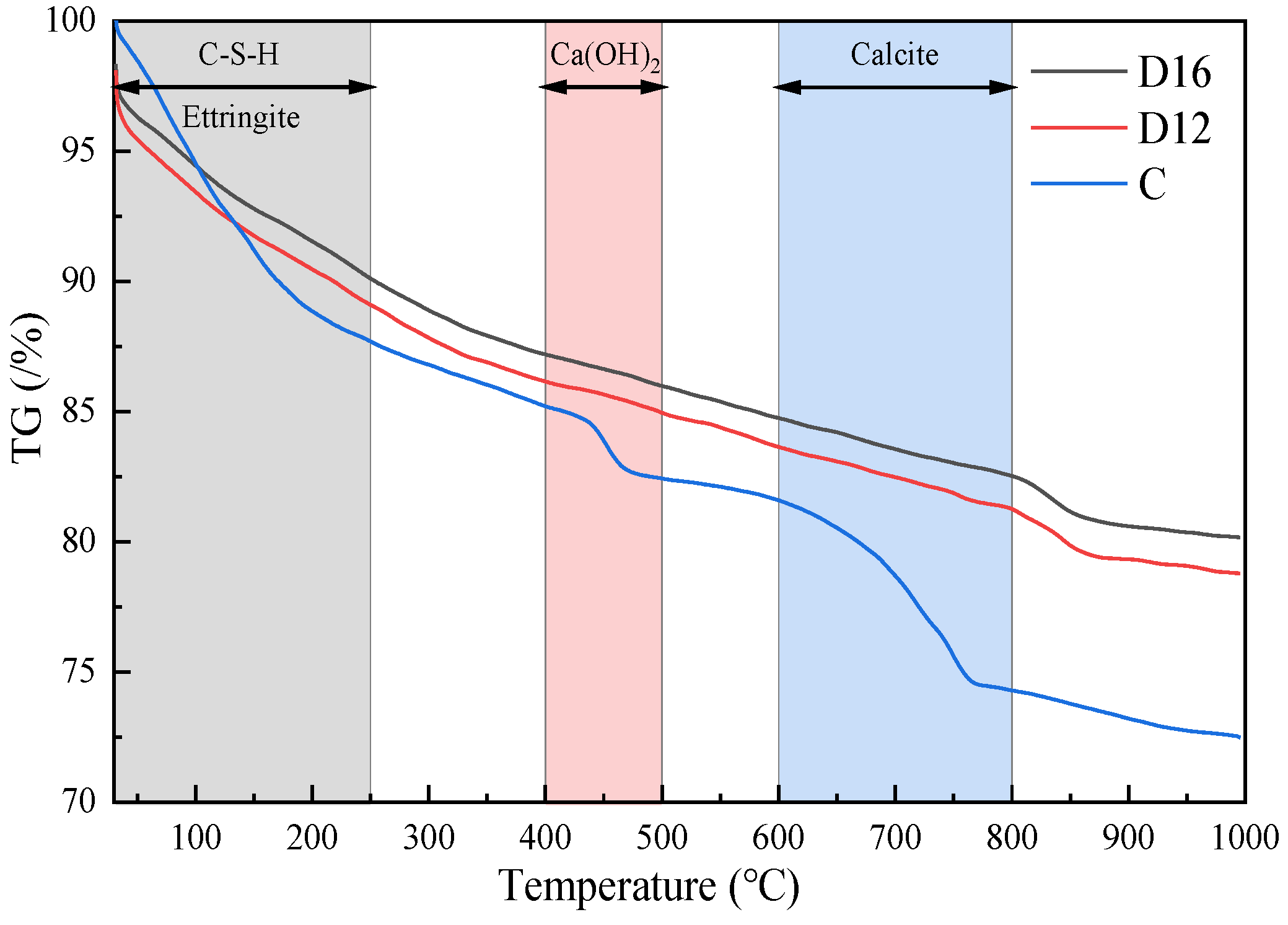
3.4. Hydration Products’ Quantitative Analysis Test Results

Figure 11 and Figure 12 show the 28 d thermogravimetric and differential scanning calorimetric analyses of the cement (C) and iron tailings–cement-based supplementary cementitious materials. There are two exothermic peaks, 404.25 °C and 476.25 °C, and three heat absorption peaks, 89.25 °C, 438.75 °C, and 683.75 °C, in all materials. Ettringite dehydration is the main reason for the generation of heat absorption peaks from room temperature to 250 °C. The heat absorption peak at 476.25 °C is the dehydration temperature of Ca(OH)2, and 683.75 °C is the decomposition temperature of ettringite with CO2 from air to form carbonate.
When the temperature of the D12 sample rises from room temperature to 250 °C, there are two obvious heat absorption peaks at 79.75 °C and 118.75 °C, and the D12 sample’s mass, during the process from room temperature to 250 °C, shows a substantial decrease, which can show that the sample contains bundles of ettringite and C-(A)-S-H gel. The three samples C, D12, and D16 have the same heat absorption peak around 476 °C; the range of 400–500 °C signifies Ca(OH)2 decomposition. It can be seen that the content of Ca(OH)2 in C > D12 > D16, respectively, is 7.3%, 2.4%, and 2.2%. The range of 600–800 °C is the weight loss peak of carbonate; unlike sample C, samples D12 and D16 do not show obvious heat absorption peaks in the range of 600–800 °C.
The mass loss of sample C and iron tailings–cement-based supplementary cementitious materials D12 and D16 was 27.5%, 21.2%, and 19.8%, respectively, when the tests were conducted from room temperature up to 1000 °C. The test results showed the presence of more hydration products in the D12 sample of the iron tailing-based composite admixture, where the ratio of SL to SS was the main factor causing the change in the 28 d compressive strength of the SCMs. Combined with X-ray diffraction patterns, it was shown that SL and SS at the appropriate ratio can provide more active ingredients to the SCM system, which in turn promotes strength enhancement. Also, based on the TG curves of the three samples shown in Figure 12, it can be concluded that the contents of ettringite and C-(A)-S-H gels of C > D12 > D16 were 12.3%, 10.9%, and 9.9%, respectively, and the Ca(OH)2 contents of C > D16 > D12 were 2.7%, 1.2%, and 1.1%, respectively. The content of carbonate of C > D12 > D16 was 7.3%, 2.4%, and 2.2%, respectively, which shows that the hydration product ettringite, C-S-H gel, and the change in calcium hydroxide content are the main factors causing the 28 d compressive strength of the SCMs [2].
In order to study more intuitively, accurately, and specifically the extent of the 28 d reaction of the SCMs with cement, based on the mass fraction of heat loss in the thermogravimetric analysis, the following reaction equations can be formed [61]:
Ca OH 2 = CaO + H 2 O
Ca OH 2 + CO 2 = CaCO 3 + H 2 O
The non-evaporated water content and Ca(OH)2 content at 28 d of age are calculated as follows:
H 2 O = A + B + C × 18 ÷ 44
Ca ( OH ) 2 = B × 74 ÷ 18 + C × 18 ÷ 44
where A, B, and C correspond to the percentage of weight loss caused by dehydration of ettringite, Ca(OH)2 decomposition, and CaCO3 decomposition in the thermogravimetric analysis curves, respectively. Moreover, 18, 44, and 74 are the relative molecular masses of H2O, CO2, and Ca(OH)2, respectively. The mass fractions of the weight loss peaks corresponding to the above three dehydration changes and decomposition changes are listed below, and the contents of non-evaporated water and the hydration product Ca(OH)2 at the age of 28 d derived from the TG-DSC curves and related calculations are shown in Table 5.
From Table 5, it can be seen that throughout the hydration process, the C sample has the highest content of bound water and Ca(OH)2. According to the change in Ca(OH)2 content in the table, the SCMs participate in the hydration reaction to produce ettringite and C-S-H gel by consuming the Ca(OH)2 in the system. The loss of Ca(OH)2 in sample D16 is greater than that in sample D12, suggesting that more Ca(OH)2 was used in the secondary hydration reaction in sample D12 [33]. Unlike the weight loss of Ca(OH)2, the weight loss of ettringite and C-S-H gel was greater in D16 than in D12, which may be due to the different ratios of IOTs, FA, SS, and GBFS leading to the dissolution of reactive silica and alumina in the composite dope, which in turn limits the generation of ettringite and C-S-H gel.

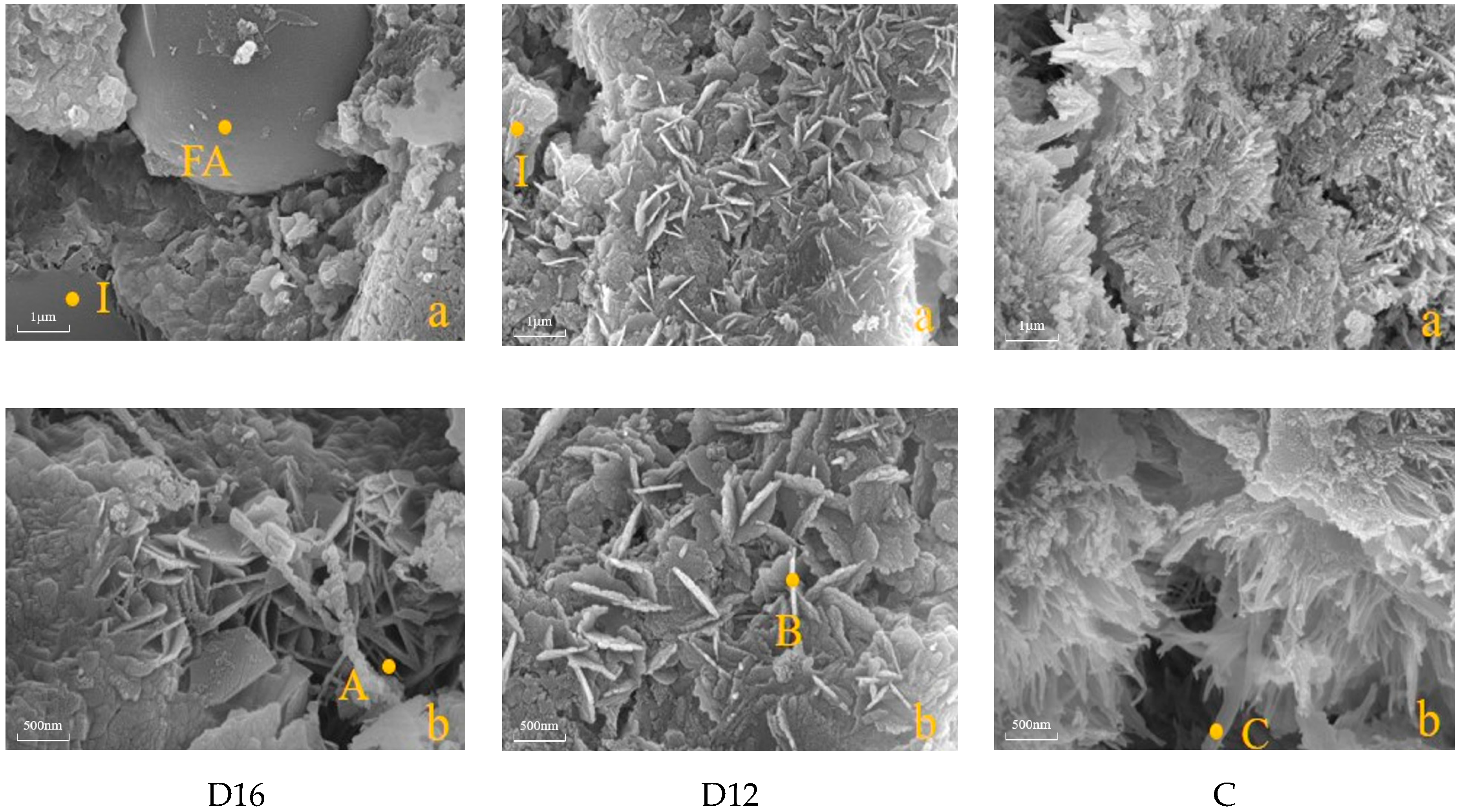
3.5. Micromorphological Analysis of Hydration Products’ Test Results

SEM is capable of analysing the morphological characteristics of the hydration products and thus clarifying the structure and type of hydration products. Figure 13 shows the 28 d SEM images of the SCMs scaled up to the micron scale (Figure 13a) and nanoscale (Figure 13b). Ca(OH)2 sheets and needle-shaped ettringite crystals as well as fibre-type-I C-S-H gels and other forms of C-S-H gels can be seen for all of the samples in Figure 13. Some type-I C-S-H gels have bifurcation at the end, and the longer the end, the less bifurcation; a few C-S-H gels form needles, and Ca(OH)2, ettringite crystals, and C-S-H gel are connected to form a reticulated space structure [60].
As can be seen in Figure 13, the proportion of different solid wastes in the SCMs affects the composition and microscopic morphology of the hydration products. At a higher SS:SL ratio of 4:1, the hydration products are mainly dominated by needle-shaped ettringite, type-I C-(A)-S-H gel, and flaky Ca(OH)2 (Figure 13: D16 b), while a small amount of spiny spherical hydrated C-S-H gel can be observed adhering to the surface of the more intact iron tailing particles (Figure 13: D16 a), indicating that the iron tailing particles of the SCMs can provide more nucleation sites for the hydration products but participate in the hydration reaction to a lesser extent due to the limited active components they contain. At an SS:SL ratio of 3:2, the hydration products are mainly type-I C-(A)-S-H gels and flaky Ca(OH)2 in D12 b (Figure 13: D12 b), in contrast to D12 a (Figure 13: D12 a), where no visible fly ash particles are seen. This shows that most of the FA in sample D12 ruptured and decomposed in the system in which it was exposed, releasing internally reactive silica and alumina, which then participated in the hydration reaction to produce C-(A)-S-H gels and Ca(OH)2. Reducing the SS:SL ratio while keeping the IOTs unchanged can increase the alkalinity of the hydration system, which in turn stimulates the participation of C2S and C3S in the steel slag in the hydration process to produce C-S-H gel and Ca(OH)2 [21,22]. This is consistent with the fact that the percentage weight loss of ettringite, C-(A)-S-H gels, and Ca(OH)2 is greater than that of D16 in the TG analyses. In other words, D12 generates more hydration products compared to D16, which also explains the high compressive strength of D12. The difference between the three groups of samples is that ettringite tends to grow in the pores of the hardened slurry, which is favourable to reduce the porosity of the hardened slurry and thus improve the compactness and strength of the slurry, as observed in D16 and C, but this phenomenon is not seen in D12.

4. Discussion

In this study, an orthogonal test method was used to prepare the iron tailings–cement-based supplementary cementitious materials, and the hydration mechanism and their microstructure were analysed. According to previous studies, the ionic concentration of the elements enables an analysis of the extent to which the hydration reaction takes place from an ionic point of view, which in turn explains the synergistic mechanisms between the different admixtures. Figure 14 shows Ca2+, Si4+, and Al3+ in different systems. From the figure, it can be seen that Ca2+, Si4+, and Al3+ were present in the SS system when the system underwent the dissolution of C3S and C2S with the generation of C-(A)-S-H gel, which is reflected in Equations (5) and (6). The concentration of Ca2+, Si4+, and Al3+ in the FA system behaved differently from that of SS, in which the concentration of Ca2+ was lower and the concentration of Si4+ and Al3+ was higher, mainly due to the higher content of Al2O3 in the FA, in which the reactive Al2O3 was dissolved in the water and reacted with the water to form C-(A)-S-H gel, which is specifically reflected in Equation (7). In the SL system, the Ca2+, Si4+, and Al3+ concentrations behaved similarly to those in the SS, with higher Ca2+ concentrations and lower Si4+ and Al3+ concentrations. In the SS, FA, and SL systems, Ca2+ concentration ranged from highest to lowest in the order SS > SL > FA, Si4+ concentration in the order FA > SL > SS, and Al3+ concentration in the order FA > SL > SS.
After the introduction of SL into the SS system, the Ca2+ concentration in the composite SS and SL system shows a significant decrease; the main reason for this is because the addition of slag provides Ca2+ and Al3+ in the system, in which Ca2+ participates in the hydration process to generate C-S-H gel and Al3+ participates in the hydration process to produce A-S-H gel. The increase in Al3+ promotes the hydration process in the SS and SL system, expressed by Equations (5) and (6), respectively, which in turn consumes Ca2+ and reduces the Ca2+ concentration in the SS and SL system; this is also due to the participation of Si4+ and Al3+ in the hydration process which generates C-(A)-S-H gels and also consequently leads to a reduction in the concentration of Si4+ and Al3+ in the composite system [22].
2 ( 3 CaO · SiO 2 ) + 6 H 2 O = 3 Ca OH 2 + 3 CaO · 2 SiO 2 · 3 H 2 O C - S - H
2 ( 2 CaO · SiO 2 ) + 4 H 2 O = 3 CaO · 2 SiO 2 · 3 H 2 O ( C - S - H ) + Ca OH 2
3 CaO · A 1 2 O 3 + 6 H 2 O = 3 CaO · A 1 2 O 3 · 6 H 2 O A - S - H
In the ternary system of SS-SL-FA, SS contains more Si4+ and divalent metal cation elements, SL has a large amount of calcium and aluminium elements, and FA is rich in silicon and aluminium elements. The three main raw materials play their respective roles in the composite system: SS provides Ca2+, OH, and Si4+, SL provides Ca2+ and Al3+, and FA provides a large amount of Ca2+ and Si4+. Combined with the changes in the diffraction peaks of the amphibole and the mineral composition of the IOTs, it can be seen that the IOTs are able to provide part of the Si4+ for the composite system, and the other three kinds of solid waste together promote the continuation of the hydration reaction, while SS and SL in the silica–oxygen tetrahedra and aluminium–oxygen tetrahedra continue depolymerisation, as expressed by Equations (5) and (6), so the composite system can continue to provide silicate and aluminate polymers to promote the generation of C-(A)-S-H gels [24]. Based on the analysis, IOTs, SS, FA, and SL have different degrees of influence on the mechanical properties of iron tailings–cement-based supplementary cementitious materials, and there are small differences in the role of each solid waste raw material in the reaction system of the hydration reaction. Compounding each solid waste feedstock offers a collaborative impact by increasing the compact strength of the composite slurry and the formation of more hydration products. Volumetric and long-term endurance of multi-solid iron tailing supplementary cementitious materials should be the focus of future research.

5. Conclusions

The aim of this study is to contribute to the resource utilisation of iron tailings, but there are some limitations and the proportion of iron tailings in the mixture needs to be further improved. In this paper, as a limited study, the compounding of IOTs, SS, SL, and FA was carried out by using orthogonal tests. The mechanical properties, hydration products, and microstructure of the iron tailings–cement-based supplementary cementitious materials were analysed. Based on the results, the following conclusions can be drawn.
  • When the ratio of IOTs:SS:FA:SL was 9:8:8:2, the 7 d compressive strength of iron tailings–cement-based supplementary cementitious materials was the highest. When the ratio of IOTs:SS:FA:SL was 9:6:8:4, the 28 d compressive strength of iron tailings–cement-based supplementary cementitious materials was the highest. The quantity of raw materials in the mixture affected the 28 d compressive strength of cementitious materials, and the degree of influence was SS > SL > FA. In addition, the raw materials in the composite system exhibited synergistic hydration.
  • Based on the results of the hydration product-type tests, it was found that the main hydration products in the iron tailings–cement-based supplementary cementitious materials were ettringite and C-(A)-S-H gel. In the reaction system, SL and FA provided aluminium, the calcium carbonate in SS provided carbonate, and the sulphate in monosulphoaluminate was replaced by carbonate. As the SS:SL ratio decreased, the degree of polymerisation of the silica–oxygen tetrahedra increased, producing a more stable ettringite, which improved the strength and microstructural densification of the cementitious material.
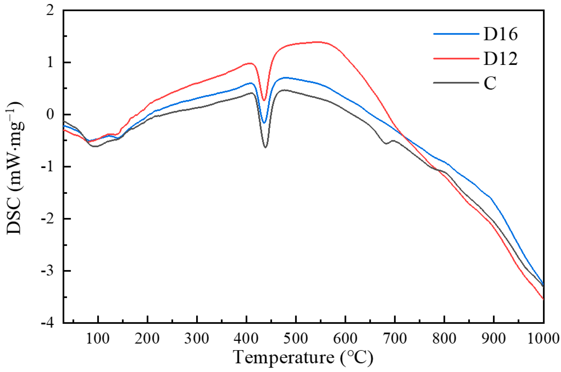
  • Based on the results of the quantitative analysis tests of the hydration products, it was found that there are two exothermic peaks and three heat-absorbing peaks in the iron tailings–cement-based supplementary cementitious materials (SCMs). When the test was carried out from room temperature to 1000 °C, the mass loss of sample C and the SCM samples D12 and D16 was 27.5%, 21.2%, and 19.8%, respectively; more hydration products existed in sample D12, the content of ettringite and C-(A)-S-H gel accounted for 10.9%, and the appropriate ratio of SL and SS provided the SCM system with more active components, which in turn promoted the improvement in strength.
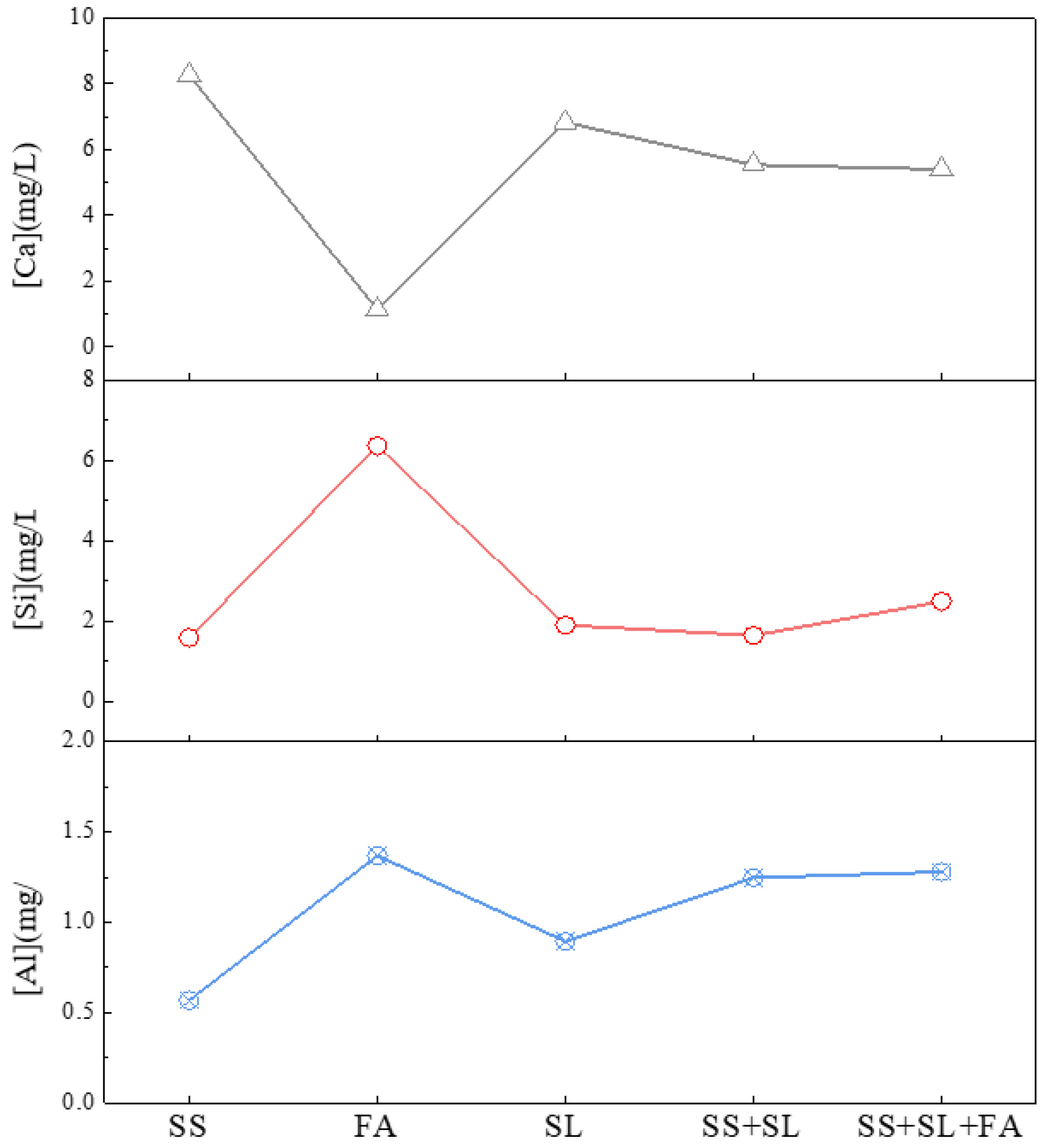
  • Based on the synergistic effect analysis results, it was found that the raw materials play their respective roles in the hybrid system and jointly promote the hydration reaction continuously. After the introduction of SL into the SS system, the hydration reaction in the SS and SL system was actively promoted by the increase in Al3+. Combined with the changes in the hornblende diffraction peaks, it can be seen that the IOTs provided part of the Si4+ for the hybrid system, and together with the other three solid wastes, they promoted the continuation of the hydration reaction and the production of C-(A)-S-H gel.

Author Contributions

Conceptualisation, Z.H. and X.G. (Xiaowei Gu); methodology, J.L.; validation, X.G. (Xiaowei Gu), S.Y. and Z.H.; formal analysis, Z.H.; investigation, S.Y. and S.W.; resources, X.G. (Xiaowei Ge); data curation, Z.H.; writing—original draft preparation, Z.H.; writing—review and editing, S.W.; visualisation, X.G. (Xiaowei Ge) and S.W.; supervision, X.G. (Xiaowei Gu); project administration, J.L.; funding acquisition, X.G. (Xiaowei Gu). All authors have read and agreed to the published version of the manuscript.

Funding

The authors are very grateful for the support of the following funds: National Key Research and Development Program of China (2023YFC3904303), National Natural Science Foundation of China (52234004).

Data Availability Statement

The raw data supporting the conclusions of this article will be made available by the authors on request.

Conflicts of Interest

The authors declare no conflicts of interest.

References

  1. Ghasemi, S.; Behnamfard, A.; Arjmand, R. Iron ore tailings valorization through separate characterization and upgradation of different tailings streams of an Iranian iron ore processing plant. Environ. Sci. Pollut. Res. 2023, 30, 115448–115460. [Google Scholar] [CrossRef] [PubMed]
  2. Wu, R.D.; Shen, Y.; Liu, J.H.; Cheng, L.N.; Zhang, G.T.; Zhang, Y.Y. Effect of Iron Tailings and Slag Powders on Workability and Mechanical Properties of Concrete. Front. Mater. 2021, 8, 723119. [Google Scholar]
  3. Segui, P.; Safhi, A.E.; Amrani, M.; Benzaazoua, M. Mining Wastes as Road Construction Material: A Review. Minerals 2023, 13, 90. [Google Scholar] [CrossRef]
  4. Zuccheratte, A.C.V.; Freire, C.B.; Lameiras, F.S. Synthetic gravel for concrete obtained from sandy iron ore tailing and recycled polyethyltherephtalate. Constr. Build. Mater. 2017, 151, 859–865. [Google Scholar] [CrossRef]
  5. Ma, B.G.; Cai, L.X.; Li, X.G.; Jian, S.W. Utilization of iron tailings as substitute in autoclaved aerated concrete: Physico-mechanical and microstructure of hydration products. J. Clean. Prod. 2016, 127, 162–171. [Google Scholar] [CrossRef]
  6. Fei, A.P.; Zhang, T.Z. Research on Performance of Pavement Cement Concrete Mixed with Iron Tailings and Fibers. In Proceedings of the 3rd International Forum on Energy, Environment Science and Materials (IFEESM), Shenzhen, China, 25–26 November 2017; pp. 348–354. [Google Scholar]
  7. Panda, L.; Biswal, S.K.; Venugopal, R.; Mandre, N.R. Recovery of Ultra-Fine Iron Ore from Iron Ore Tailings. Trans. Indian Inst. Met. 2018, 71, 463–468. [Google Scholar] [CrossRef]
  8. Zhu, Q.; Yuan, Y.X.; Chen, J.H.; Fan, L.; Yang, H. Research on the high-temperature resistance of recycled aggregate concrete with iron tailing sand. Constr. Build. Mater. 2022, 327, 126889. [Google Scholar] [CrossRef]
  9. Galvao, J.L.B.; Andrade, H.D.; Brigolini, G.J.; Peixoto, R.A.F.; Mendes, J.C. Reuse of iron ore tailings from tailings dams as pigment for sustainable paints. J. Clean. Prod. 2018, 200, 412–422. [Google Scholar] [CrossRef]
  10. Lazorenko, G.; Kasprzhitskii, A.; Shaikh, F.; Krishna, R.S.; Mishra, J. Utilization potential of mine tailings in geopolymers: Physicochemical and environmental aspects. Process Saf. Environ. Protect. 2021, 147, 559–577. [Google Scholar] [CrossRef]
  11. Huang, X.Y.; Ranade, R.; Li, V.C. Feasibility Study of Developing Green ECC Using Iron Ore Tailings Powder as Cement Replacement. J. Mater. Civ. Eng. 2013, 25, 923–931. [Google Scholar] [CrossRef]
  12. Fontes, W.C.; Mendes, J.C.; Da Silva, S.N.; Peixoto, R.A.F. Mortars for laying and coating produced with iron ore tailings from tailing dams. Constr. Build. Mater. 2016, 112, 988–995. [Google Scholar] [CrossRef]
  13. Borges, P.H.R.; Ramos, F.C.R.; Caetano, T.R.; Panzerra, T.H.; Santos, H. Reuse of iron ore tailings in the production of geopolymer mortars. REM-Int. Eng. J. 2019, 72, 581–587. [Google Scholar] [CrossRef]
  14. Fontes, W.C.; de Carvalho, J.M.F.; Defaveri, K.; Brigolini, G.J.; Segadaes, A.M.; Peixoto, R.A.F. Hydraulic Tiles Produced with Fine Aggregates and Pigments Reclaimed from Iron Ore Tailings. J. Sust. Metall. 2021, 7, 151–165. [Google Scholar] [CrossRef]
  15. Gu, X.W.; Zhang, W.F.; Zhang, X.L.; Li, X.H.; Qiu, J.P. Hydration characteristics investigation of iron tailings blended ultra high performance concrete: The effects of mechanical activation and iron tailings content. J. Build. Eng. 2022, 45, 103459. [Google Scholar] [CrossRef]
  16. Duarte, M.S.; Almada, B.S.; Santos, W.J.D.; Bessa, S.A.L.; Bezerra, A.C.D.; Aguilar, M.T.P. Influence of mechanical treatment and magnetic separation on the performance of iron ore tailings as supplementary cementitious material. J. Build. Eng. 2022, 59, 105099. [Google Scholar] [CrossRef]
  17. Bezerra, C.G.; Rocha, C.A.A.; de Siqueira, I.S.; Toledo, R.D. Feasibility of iron-rich ore tailing as supplementary cementitious material in cement pastes. Constr. Build. Mater. 2021, 303, 124496. [Google Scholar] [CrossRef]
  18. de Magalhaes, L.F.; França, S.; Oliveira, M.D.; Peixoto, R.A.F.; Bessa, S.A.L.; Bezerra, A.C.D. Iron ore tailings as a supplementary cementitious material in the production of pigmented cements. J. Clean. Prod. 2020, 274, 123260. [Google Scholar] [CrossRef]
  19. Kwon, E.; Ahn, J.; Cho, B.; Park, D. A study on development of recycled cement made from waste cementitious powder. Constr. Build. Mater. 2015, 83, 174–180. [Google Scholar] [CrossRef]
  20. Li, J.S.; Ren, W.Y.; Zhang, A.J.; Li, S.C.; Tan, J.P.; Liu, H.T. Mechanical Properties and Microstructure Analysis of Cement Mortar Mixed with Iron Ore Tailings. Buildings 2023, 13, 149. [Google Scholar] [CrossRef]
  21. Zhang, Y.N.; Yang, D.K.; Gu, X.W.; Chen, H.; Li, Z.J. Application of Iron Tailings-Based Composite Supplementary Cementitious Materials (SCMs) in Green Concrete. Materials 2022, 15, 3866. [Google Scholar] [CrossRef]
  22. Zhang, Y.N.A.; Zhang, X.K.; Gu, X.W.; Wang, T.; Liu, B.A. Study on Properties and Optimization of Ternary Auxiliary Cementing Materials for IOTs. Materials 2022, 15, 3851. [Google Scholar] [CrossRef] [PubMed]
  23. Li, J.F.; Luo, X.C.; Sun, M.K.; Shen, W.G.; Cao, B.; Li, X.L. Utilization of Steel Slags in Cement Industry. In Proceedings of the Annual Meetings of Chinese-Society’s-Building-Materials, Professional Committees of Stone and Aggregate and Utilization of Solid Waste, Wuhan, China, 28 November–1 December 2013; p. 98. [Google Scholar]
  24. Wang, Q.; Wang, Z.M.; Su, Y.W.; Wu, P.; Hu, S.G.; Chen, P.; Lyu, X.J. Application of calcareous iron ore tailings in the production of cement. Energy Sources Part A-Recovery Util. Environ. Eff. 2020, 1–10. [Google Scholar] [CrossRef]
  25. Singh, S.K.; Jyoti; Vashistha, P. Development of newer composite cement through mechano-chemical activation of steel slag. Constr. Build. Mater. 2021, 268, 121147. [Google Scholar] [CrossRef]
  26. Gao, D.; Wang, F.P.; Wang, Y.T.; Zeng, Y.N. Sustainable Utilization of Steel Slag from Traditional Industry and Agriculture to Catalysis. Sustainability 2020, 12, 9295. [Google Scholar] [CrossRef]
  27. Xiang, X.D.; Xi, J.C.; Li, C.H.; Jiang, X.W. Preparation and application of the cement-free steel slag cementitious material. Constr. Build. Mater. 2016, 114, 874–879. [Google Scholar] [CrossRef]
  28. Zhou, M.K.; Cheng, X.; Chen, X. Studies on the Volumetric Stability and Mechanical Properties of Cement-Fly-Ash-Stabilized Steel Slag. Materials 2021, 14, 495. [Google Scholar] [CrossRef]
  29. Dindi, A.; Quang, D.V.; Vega, L.F.; Nashef, E.; Abu-Zahra, M.R.M. Applications of fly ash for CO2 capture, utilization, and storage. J. CO2 Util. 2019, 29, 82–102. [Google Scholar] [CrossRef]
  30. Hou, H.M.; Su, L.J.; Guo, D.F.; Xu, H. Resource utilization of solid waste for the collaborative reduction of pollution and carbon emissions: Case study of fly ash. J. Clean. Prod. 2023, 383, 135449. [Google Scholar] [CrossRef]
  31. Zhang, C.; Fu, J.X.; Song, W.D.; Du, C.F.; Fu, H.T. High-volume ultrafine fly ash-cement slurry mechanical properties and strength development model establishment. Constr. Build. Mater. 2021, 277, 122350. [Google Scholar] [CrossRef]
  32. Yang, J.; Hu, H.C.; He, X.Y.; Su, Y.; Wang, Y.B.; Tan, H.B.; Pan, H. Effect of steam curing on compressive strength and microstructure of high volume ultrafine fly ash cement mortar. Constr. Build. Mater. 2021, 266, 120894. [Google Scholar] [CrossRef]
  33. Sun, C.Y.; Zhang, J.; Yan, C.W.; Yin, L.Q.; Wang, X.X.; Liu, S.G. Hydration characteristics of low carbon cementitious materials with multiple solid wastes. Constr. Build. Mater. 2022, 322, 126366. [Google Scholar] [CrossRef]
  34. Yang, W.H.; Hwang, J.S.; Jeon, C.; Lee, S.-H. An Experimental Study on the Chloride Attack Resistibility of Alkali-Activated Ternary Blended Cement Concrete. J. Korea Inst. Build. Constr. 2016, 16, 321–329. [Google Scholar] [CrossRef]
  35. Song, R.J.; Zhao, Q.X.; Zhang, J.R.; Liu, J.Z. Microstructure and Composition of Hardened Paste of Soda Residue-Slag-Cement Binding Material System. Front. Mater. 2019, 6, 211. [Google Scholar] [CrossRef]
  36. Cheng, Y.Z.; Bai, L.; Du, W.J.; Chen, L.J.; Yan, Y.L. Engineered cementitious composites using powder regenerated from municipal solid waste incineration bottom ash as supplementary cementitious material. Constr. Build. Mater. 2023, 394, 132224. [Google Scholar] [CrossRef]
  37. Jin, R.Y.; Chen, Q.; Soboyejo, A. Survey of the current status of sustainable concrete production in the US. Resour. Conserv. Recycl. 2015, 105, 148–159. [Google Scholar] [CrossRef]
  38. Carette, J.; Staquet, S. Monitoring and modelling the early age and hardening behaviour of eco-concrete through continuous non-destructive measurements: Part II. Mechanical behaviour. Cem. Concr. Compos. 2016, 73, 1–9. [Google Scholar] [CrossRef]
  39. Zhang, W.; Wei, C.; Liu, X.M.; Zhang, Z.Q. Effect of Phosphorus Slag Admixture on the Properties and Hydration Mechanism of Circulating Fluidized Bed Fly Ash-Based Multi-Solid Waste Cementitious Material. Materials 2022, 15, 6774. [Google Scholar] [CrossRef] [PubMed]
  40. He, Z.H.; Du, S.G.; Chen, D. Microstructure of ultra high performance concrete containing lithium slag. J. Hazard. Mater. 2018, 353, 35–43. [Google Scholar] [CrossRef] [PubMed]
  41. Liu, J.; Liu, G.; Zhang, W.Z.; Li, Z.L.; Xing, F.; Tang, L.P. Application potential analysis of biochar as a carbon capture material in cementitious composites: A review. Constr. Build. Mater. 2022, 350, 128715. [Google Scholar] [CrossRef]
  42. Miller, S.A.; Horvath, A.; Monteiro, P.J.M. Readily implementable techniques can cut annual CO2 emissions from the production of concrete by over 20%. Environ. Res. Lett. 2016, 11, 074029. [Google Scholar] [CrossRef]
  43. Supriya; Chaudhury, R.; Sharma, U.; Thapliyal, P.C.; Singh, L.P. Low-CO2 emission strategies to achieve net zero target in cement sector. J. Clean. Prod. 2023, 417, 137466. [Google Scholar] [CrossRef]
  44. Wu, X.; Li, B.; Wei, D.B.; Guo, F.C.; Ji, H.D. Investigation of Preparation and Shrinkage Characteristics of Multi-Source Solid Waste-Based Cementitious Materials. Materials 2023, 16, 7522. [Google Scholar] [CrossRef] [PubMed]
  45. Shmlls, M.; Abed, M.A.; Horvath, T.; Bozsaky, D. Sustainability framework of recycled aggregate concrete produced with supplementary cementitious materials. Ain Shams Eng. J. 2023, 14, 102036. [Google Scholar] [CrossRef]
  46. Shen, L.L.; Zhang, J.X.; Lai, W.A.; Li, M.; Huo, B.B. Microstructure and mechanical behaviors of coal gangue-Coal slime water backfill cementitious materials. J. Mater. Res. Technol. 2022, 20, 3772–3783. [Google Scholar] [CrossRef]
  47. Zhang, X.; Qian, C.X.; Ma, Z.Y.; Li, F. Study on preparation of supplementary cementitious material using microbial CO2 fixation of steel slag powder. Constr. Build. Mater. 2022, 326, 126864. [Google Scholar] [CrossRef]
  48. Tao, M.; Lu, D.M.; Shi, Y.; Wu, C.Q. Utilization and life cycle assessment of low activity solid waste as cementitious materials: A case study of titanium slag and granulated blast furnace slag. Sci. Total Environ. 2022, 849, 157797. [Google Scholar] [CrossRef]
  49. Khaidarov, B.B.; Suvorov, D.S.; Lysov, D.V.; Abramov, A.K.; Luchnikova, G.G.; Khaidarov, T.B.; Kuznetsov, D.V.; Bychkov, A.V.; Burmistrov, I.N.; Mamulat, S.L. Production and Investigation of a Finely Dispersed Fraction of Blast-Furnace Granulated Slag for Use as Components of Clinker-Free Binders. Refract. Ind. Ceram. 2021, 62, 347–354. [Google Scholar] [CrossRef]
  50. Pinto, P.S.; Milagre, L.E.; Moreira, L.C.M.; Rocha, H.P.; Salviano, A.B.; Ardisson, J.D.; Parreira, F.V.; Teixeira, A.P.C.; Lago, R.M. Iron Recovery from Iron Ore Tailings by Direct Hydrogen Reduction at Low Temperature and Magnetic Separation. J. Braz. Chem. Soc. 2022, 33, 969–977. [Google Scholar] [CrossRef]
  51. Wu, S.Z.; Zhou, Y.; Li, R.F.; Liu, X.Q.; Li, C.W.; Huang, Z.Y. Reaction Sintered Porous Ceramics Using Iron Tailings: Preparation and Properties. J. Inorg. Mater. 2023, 38, 1193–1199. [Google Scholar] [CrossRef]
  52. Zhang, Z.S.; Lian, F.; Ma, L.J.; Jiang, Y.S. Effects of Quicklime and Iron Tailings as Modifier on Composition and Properties of Steel Slag. J. Iron Steel Res. Int. 2015, 22, 15–20. [Google Scholar] [CrossRef]
  53. Adesina, A.; Das, S. Durability Evaluation of Green-Engineered Cementitious Composite Incorporating Glass as Aggregate. J. Mater. Civ. Eng. 2020, 32, 04020354. [Google Scholar] [CrossRef]
  54. Yao, G.; Wang, Q.; Wang, Z.M.; Wang, J.X.; Lyu, X.J. Activation of hydration properties of iron ore tailings and their application as supplementary cementitious materials in cement. Powder Technol. 2020, 360, 863–871. [Google Scholar] [CrossRef]
  55. Wei, J.Q.; Gencturk, B.; Jain, A.; Hanifehzadeh, M. Mitigating alkali-silica reaction induced concrete degradation through cement substitution by metakaolin and bentonite. Appl. Clay Sci. 2019, 182, 105257. [Google Scholar] [CrossRef]
  56. Choi, Y.-W.; Rok, O.S.; Seok, P.M.; Choi, B.-K. The Experimental Study on the Fluidity Properties of Mortar Using Basalt Fiber and High Volume Fly Ash. J. Korean Recycl. Constr. Resour. Inst. 2014, 2, 345–353. [Google Scholar]
  57. Libre, N.A.; Khoshnazar, R.; Shekarchi, M. Relationship between fluidity and stability of self-consolidating mortar incorporating chemical and mineral admixtures. Constr. Build. Mater. 2010, 24, 1262–1271. [Google Scholar] [CrossRef]
  58. Gu, X.W.; Wang, H.Y.; Zhu, Z.G.; Liu, J.P.; Xu, X.C.; Wang, Q. Synergistic effect and mechanism of lithium slag on mechanical properties and microstructure of steel slag-cement system. Constr. Build. Mater. 2023, 396, 131768. [Google Scholar] [CrossRef]
  59. Xu, W.X.; Chen, H.S. Numerical investigation of effect of particle shape and particle size distribution on fresh cement paste microstructure via random sequential packing of dodecahedral cement particles. Comput. Struct. 2013, 114, 35–45. [Google Scholar] [CrossRef]
  60. Wang, X.Y. Analysis of hydration kinetics and strength progress in cement-slag binary composites. J. Build. Eng. 2021, 35, 101810. [Google Scholar] [CrossRef]
  61. Suraneni, P.; Weiss, J. Examining the pozzolanicity of supplementary cementitious materials using isothermal calorimetry and thermogravimetric analysis. Cem. Concr. Compos. 2017, 83, 273–278. [Google Scholar] [CrossRef]
Figure 1. Flow chart describing the methodology.
Buildings 14 01044 g001
Figure 2. XRD test results of raw materials.
Buildings 14 01044 g002
Figure 3. Raw material particle size analysis test results.
Buildings 14 01044 g003
Figure 4. SEM pictures of I (a), SS (b), FA (c), and SL (d).
Buildings 14 01044 g004
Figure 5. Compressive strength at different ages.
Buildings 14 01044 g005
Figure 6. Flowability of mortar with different mixture proportions.
Buildings 14 01044 g006
Figure 7. Cumulative particle size distribution.
Buildings 14 01044 g007
Figure 8. Particle size distribution.
Buildings 14 01044 g008
Figure 9. XRD patterns of the pastes at 28 d. 1—Ca(OH)2; 2—Aft; 3—Quartz; 4—C3S.
Buildings 14 01044 g009
Figure 10. FTIR spectra of pastes.
Buildings 14 01044 g010
Figure 11. DSC curves of pastes.
Buildings 14 01044 g011
Figure 12. TG curves of pastes.
Buildings 14 01044 g012
Figure 13. SEM images of D16; D12; C at 28 d.
Buildings 14 01044 g013
Figure 14. Ion concentrations in different systems.
Buildings 14 01044 g014
Table 1. Physicochemical properties of raw materials.
Chemical Composition
(wt. %)
Materials
PCIOTsSSFAGBFS
SiO228.1670.4615.2060.2034.50
Al2O37.440.912.5329.3917.70
CaO54.862.6842.652.4934.00
Fe2O32.7614.5427.543.781.03
MgO2.3711.296.050.516.01
SO32.320.120.120.261.64
Specific surface area
(m2/g)
1.010.830.971.021.23
Table 2. Mixture design based on orthogonal methods.
MixtureMix ProportionLevels
PCIOTsSSFAGBFSSandWaterSSFAGBFS
D1315453030301350225111
D245183636122
D345133939133
D445104040144
D545361836212
D645363618221
D745203040234
D845204030243
D945391339313
D1045302040324
D1145393913331
D1245304020342
D1345401040414
D1445402030423
D1545403020432
D1645404010441
Table 3. Orthogonal test results for compressive strength.
MixtureLevels of the Composite SCMsCompressive Strength
SSFAGBFS7 d28 d
D111121.032.2
D212222.731.3
D313322.934.5
D414420.930.2
D521222.131.0
D622118.632.7
D723423.134.3
D824317.431.7
D931321.133.6
D1032420.233.1
D1133119.028.3
D1234218.035.0
D1341420.723.1
D1442321.030.3
D1543224.732.0
D1644124.832.2
Table 4. Range analysis of orthogonal tests.
AgeFactorSSFAGBFS
7 d K ¯ 1 21.87521.22520.850
K ¯ 2 20.30020.62521.925
K ¯ 3 19.57522.47520.600
K ¯ 4 22.85020.27521.225
R 1 3.2752.2001.325
28 d K ¯ 1 32.05029.97531.350
K ¯ 2 32.42531.85032.325
K ¯ 3 32.50032.27532.525
K ¯ 4 29.40032.27530.175
R 2 3.1002.3002.350
Table 5. Content of non-evaporated water and Ca(OH)2 in hydration products.
NO.Ettringite and C-S-H Gel Dehydration Weight LossCa(OH)2 Decomposition Weight LossCaCO3 Decomposition Weight LossTotal LossH2OCa(OH)2
D169.9 1.22.219.812.005.83
D1210.91.12.421.212.985.50
C12.32.77.327.517.9914.09
Disclaimer/Publisher’s Note: The statements, opinions and data contained in all publications are solely those of the individual author(s) and contributor(s) and not of MDPI and/or the editor(s). MDPI and/or the editor(s) disclaim responsibility for any injury to people or property resulting from any ideas, methods, instructions or products referred to in the content.

