1. Introduction
Steel–concrete composite beams are extensively used in large-span bridges and buildings because of their excellent cross-sectional properties. However, the concrete at the support, which is subjected to hogging moments, is prone to tension-induced cracking, posing a threat to the structure’s durability and stiffness. Addressing this concern commonly involves the enhancement of the concrete properties in the tensile zone to elevate its cracking load and reduce the occurrence rate and crack widths. Illustrative engineering approaches include the use of prestressed concrete [
1,
2,
3], fiber-reinforced concrete [
4,
5], engineered cementitious composites [
6], ultrahigh-performance concrete [
7,
8], and the incorporation of high-performance concrete overlays utilizing a wire mesh atop conventional concrete slabs [
9]. Another practical measure involves modifying the form of the shear connectors. Conventional headed studs welded to steel girders are in direct contact with both the concrete and the girder, which renders the concrete susceptible to tension cracking. Consequently, connectors have been developed to enable sliding between the steel girder and concrete slab, thereby relieving tension stresses in the concrete subjected to hogging moments. Nie et al. [
10] and Li et al. [
11] proposed three new uplift-restricted and slip-permitted connectors—that is, a sliding-type, T-shape, and screw-type—that could improve the crack resistance of concrete slabs without weakening the overall stiffness and ultimate capacity of the composite beams. Su et al. [
12,
13] investigated the effects of rubber-sleeved stud connectors using experiments and simulations and concluded that these connectors exhibited limited interactions and could reduce the risk of cracking with little or no impact on the shear strength. High-strength bolted connectors with sliding characteristics could also relieve tensile stresses in concrete. Hogging moment tests [
14,
15] have demonstrated that composite beams with high-strength bolted connectors displayed enhanced crack resistance compared with their counterparts with conventional welded studs. Thus, high-strength bolted connectors that can transmit forces by sliding through installation apertures should be examined for their potential to suppress concrete cracks when subjected to hogging moments.
In addition to their aforementioned benefits of crack resistance, the ease of deconstruction and installation of bolted connectors that align with sustainable development and prefabricated building trends has resulted in increased attention on the use of bolted connectors in recent years. Consequently, extensive studies have been undertaken on bolted connectors. Push-off tests conducted by Dai et al. [
16] demonstrated that deconstructable threaded stud connectors exhibited bearing capacities similar to those of welded studs. Ataei et al. [
17] further demonstrated that composite beams incorporating high-strength bolted connectors exhibited greater ductility compared with those featuring conventional welded studs. Using single-shear connector tests, Kwon et al. [
18] concluded that post-installed, high-strength bolted connectors had superior fatigue strength compared with the strength of welding studs.
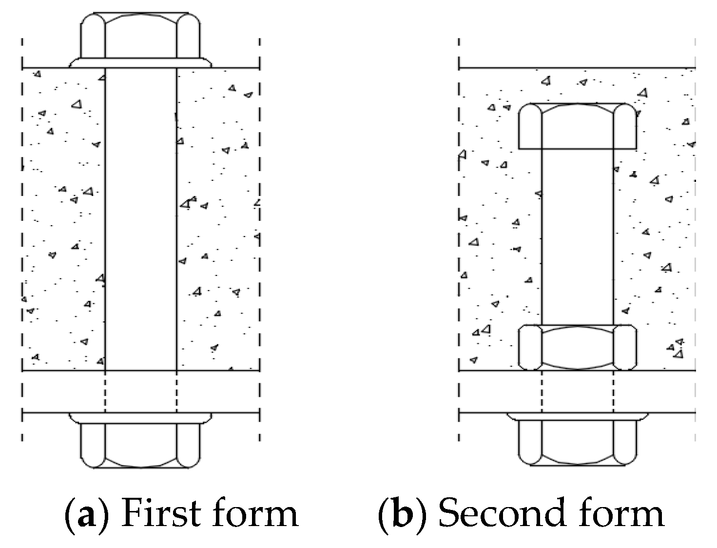
Two main types of high-strength bolted connectors are shown in
Figure 1. Both tend to transmit shear forces due to the generated friction by applying pretension to the high-strength bolts. This frictional transfer mechanism enables a composite beam with a partial shear connection to achieve an initial stiffness close to that of a beam with a full shear connection [
17]. Sliding occurs when the interface shear exceeds the maximum friction, and stops when the bolted shank is obstructed by the hole wall. This can be summarized in the “full–zero–full” shear-interaction model [
19]; the mechanism can be advantageous in inhibiting the cracking of concrete subjected to tension. In a push test conducted to determine the load-carrying capacity of connectors, Lee et al. [
19] attributed the load–slip curve to three distinctive stages of full–zero–partial interaction. Based on experimental tests and finite element (FE) analysis, Liu et al. [
20] demonstrated the three distinct stages of the load–slip response, namely the early strong stiffness, sliding after overcoming friction, and third-stage characteristics following bearing pressure. Zhang et al. [
21] summarized these four stages—that is, frictional transfer, slip, bolt shank transfer, and failure. Moreover, there are two modes of failure—that is, shearing of the high-strength bolts and crushing of the concrete—depending on their relative strengths [
22]. In the quasistatic tests of full-size composite beams conducted by Ataei et al. [
17], the final failure mode was characterized by splitting failure and eventual crushing of the concrete. However, to our knowledge, very few research studies [
6,
9,
11,
14,
15] have been conducted on the load–slip characteristics and failure modes of hogging sections.
Using the existing Chinese GB 50017 [
23] and Eurocode 4: Design of Composite Steel and Concrete Structures [
24] standards, the shear capacity of connectors of composite beams can be calculated from two perspectives—that is, the connector fracture and localized concrete failure. High-strength bolts can also be considered based on two distinct modes of failure that have been studied. In tests conducted by Kwon et al. [
18] and Liu et al. [
20], the high-strength bolts sheared off; thus, their proposed equations were only multiplied by a correction factor based on pure shear. Du et al. [
25,
26] introduced a correction to account for the effects of the embedded slender ratio based on localized concrete failure. Zhang et al. [
21] modified the equations corresponding to two failure modes at the same time. Chen et al. [
27] proposed a fitting equation considering the concrete strength, bolt diameter, and strength. Pavlovic et al. [
28] divided the bolted shear capacity in push-out tests into four components—pure shear resistance, catenary force, nut friction, and concrete friction. However, in the reverse push-out tests conducted by Zhou et al. [
29], the concrete slabs tended to separate from each other. Consequently, the friction between the concrete and the steel girder should be neglected. Moreover, in the hogging moment region, the performance of each component can be weakened owing to concrete tension. Consequently, the existing equations do not accurately express the bolted shear capacity within concrete subjected to tension.
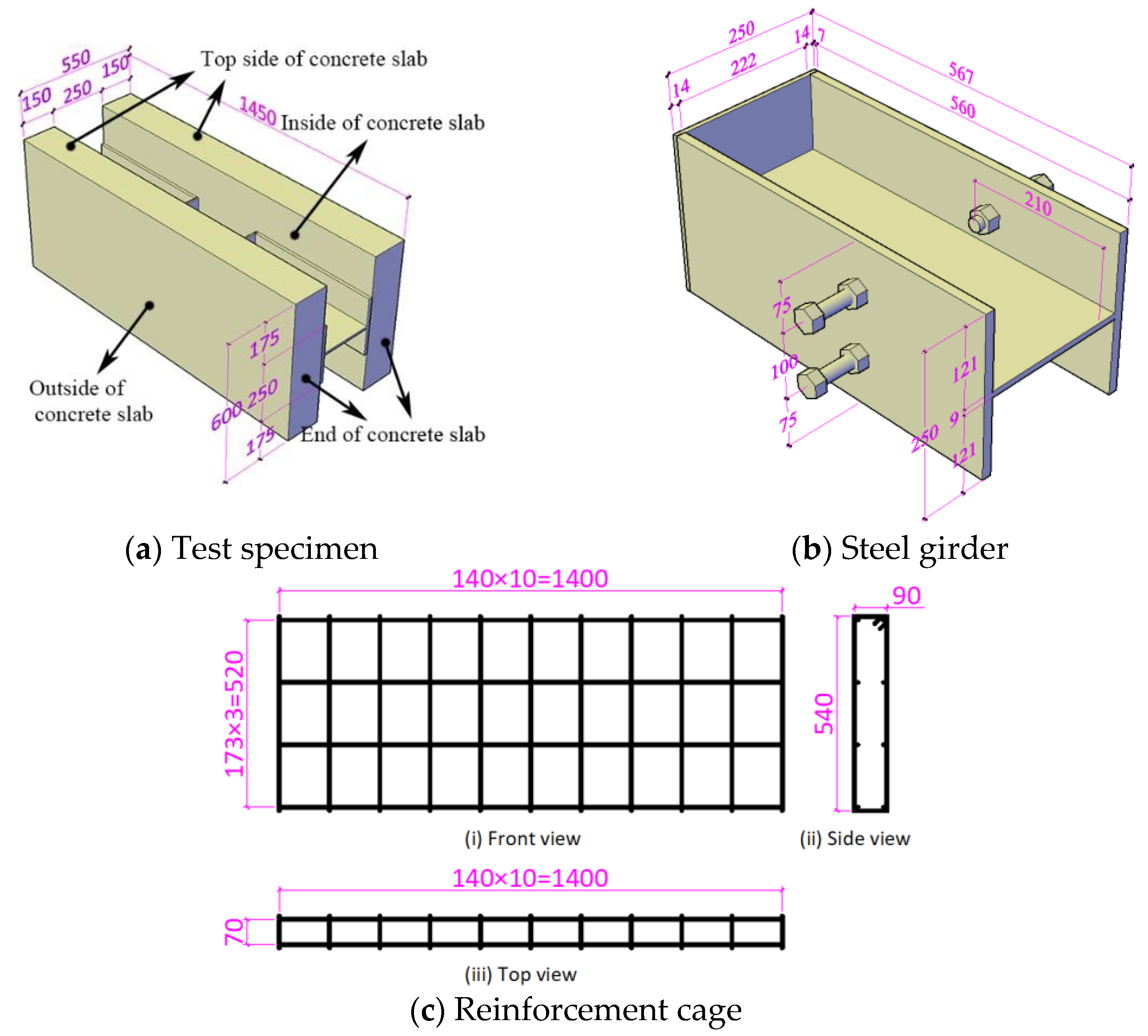
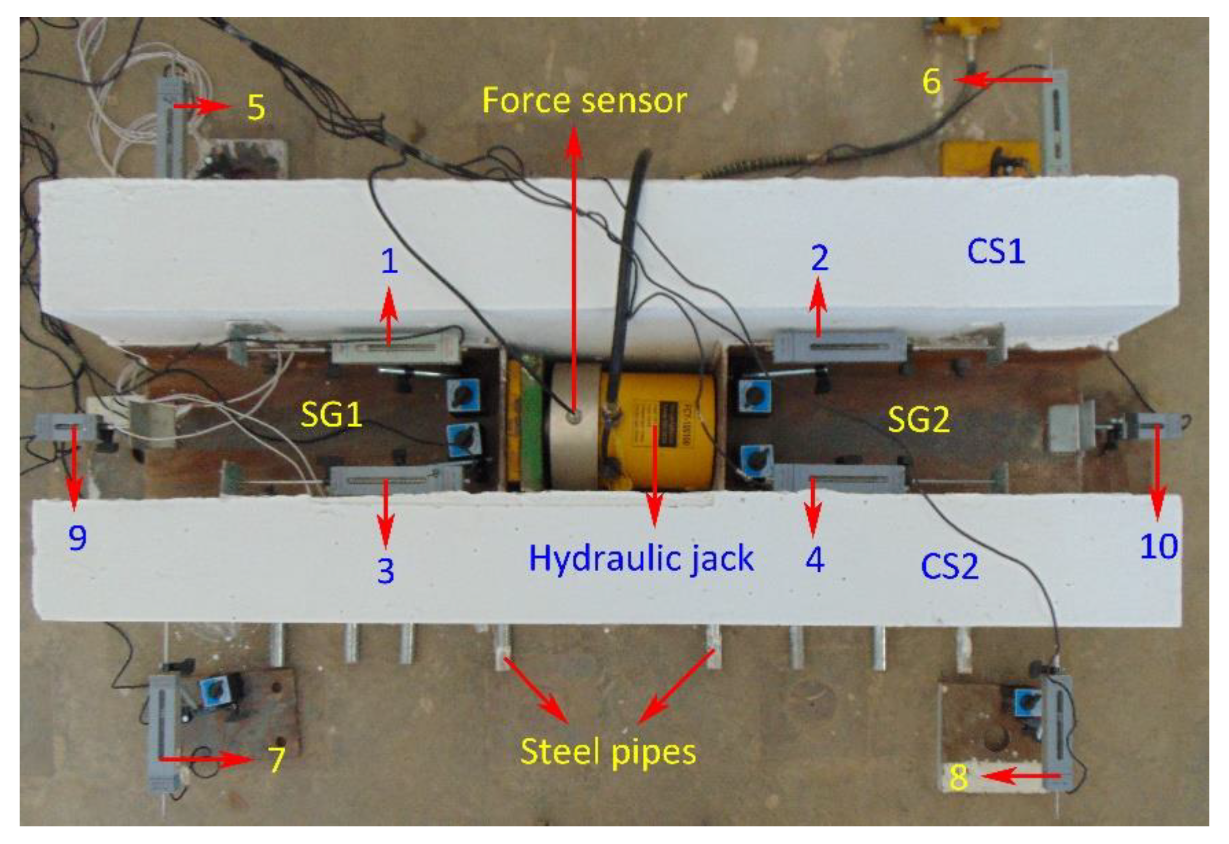
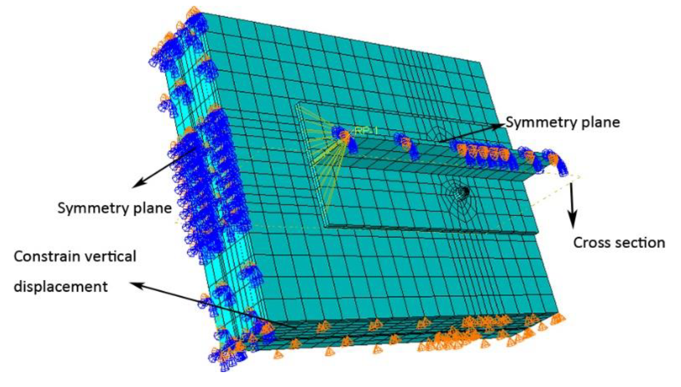
Although extensive literature exists on high-strength bolted connectors, research on their shear performance subjected to hogging moments is notably lacking. Our study pioneered the use of a reverse push-out test procedure to investigate the performance of high-strength bolted connectors in concrete subjected to tension. The adoption of high-strength bolted connectors with sliding characteristics in the hogging moment region of steel–cement composite structures can improve the crack resistance of concrete at the support. Four reverse push-out specimens were specifically designed to scrutinize their performance when the concrete is subjected to tension induced by hogging moments. A cost-effective and time-saving FE model (each model required about 6 h to execute) was developed to examine the internal microstates of the specimens, after which a correction factor for the shear capacity of bolts within concrete subjected to tension was proposed.
5. Shear Resistance of Single Bolt
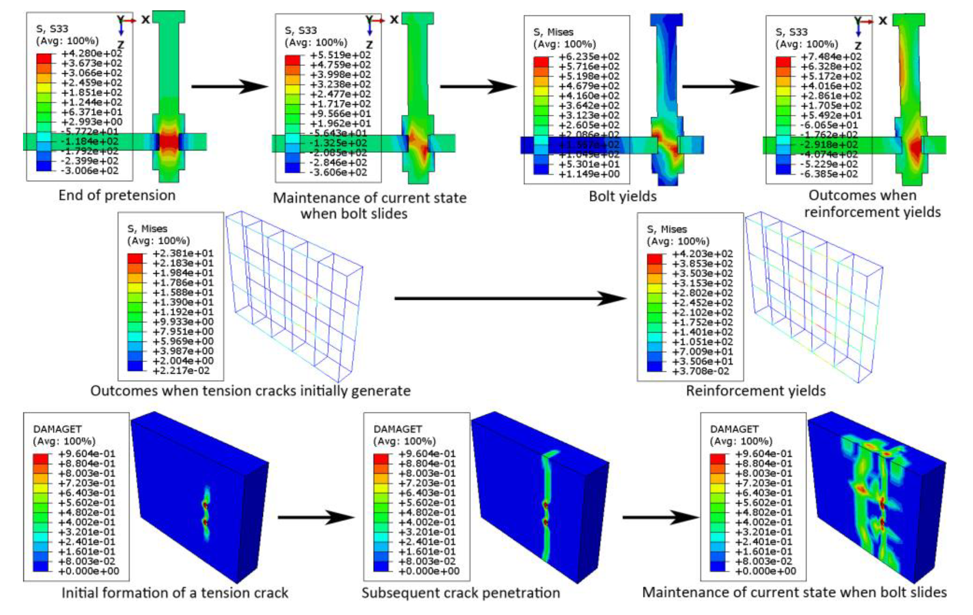
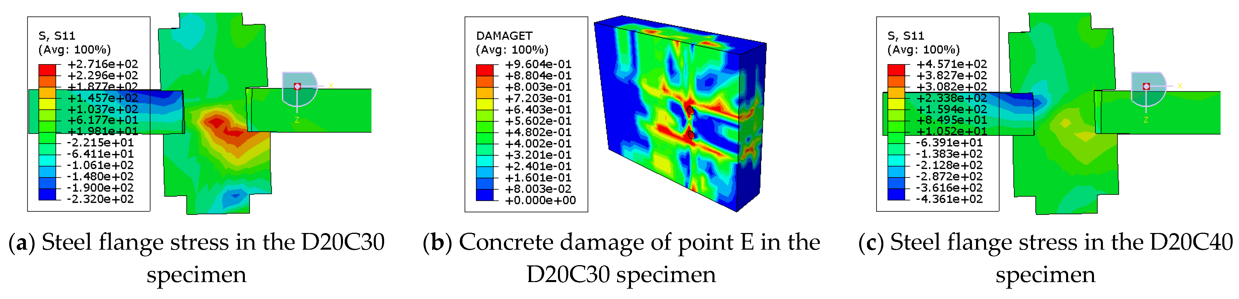
When failure occurs as the connector is sheared off, the shear capacity in the reverse push-out tests should be the same as that in the conventional push-out tests. However, the experimental and numerical results were considerably smaller than the values calculated in various codes and studies. The FE results showed that the failure mode of the reverse push-out specimens was mainly localized compressive crushing of the concrete. Considering that the contribution of both the concrete and connectors to the shear capacity is weakened within concrete under tension, a discount factor (
λ) can be introduced to correct the capacity. According to Ref. [
23],
λ was set to 0.9, which is higher than the results of our tests and numerical simulations; this value is suitable for studs but not for high-strength bolts. This localized failure is directly affected by the concrete strength and bearing area and is closely related to the bolt diameter. Consequently, the following discount factor was proposed,
where
denotes the reduction coefficient,
denotes the compressive strength of concrete (MPa),
denotes the bolt diameter (mm), and
,
,
, and
.
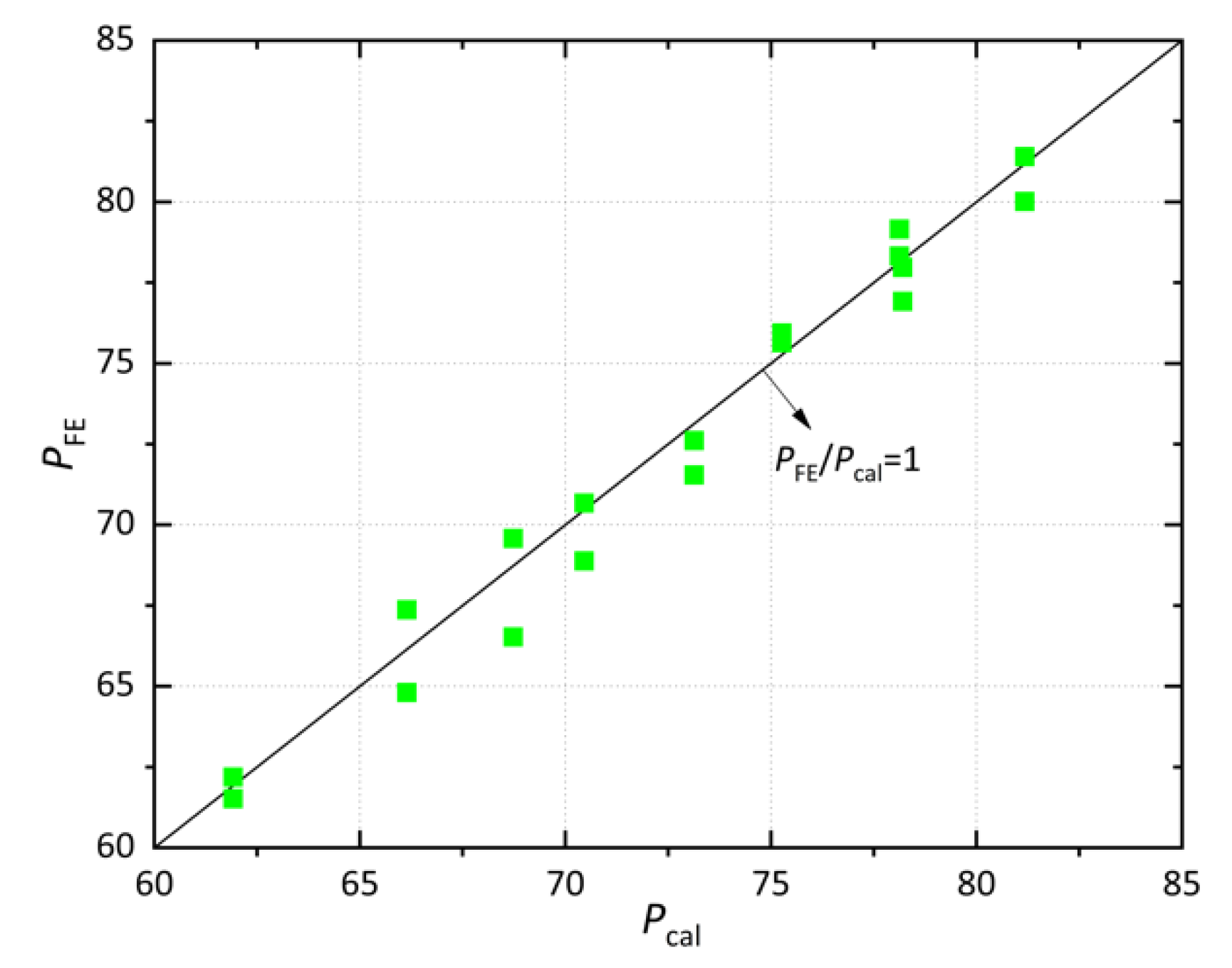
The modified version of the shear capacity of high-strength bolts applicable to the hogging moment section based on [
23] is expressed by Equation (5). The values of
α,
β,
γ, and
were obtained by nonlinear fitting using SPSS 26 based on the FE results. As shown in
Figure 19, the corrected equation describes more accurately the shear-bearing capacity of high-strength bolts within concrete under tension.
6. Conclusions
Four reverse push-out specimens were constructed to investigate the performance of high-strength bolted shear connectors when concrete is subjected to tension in hogging moment conditions. The following conclusions can be drawn:
- (1)
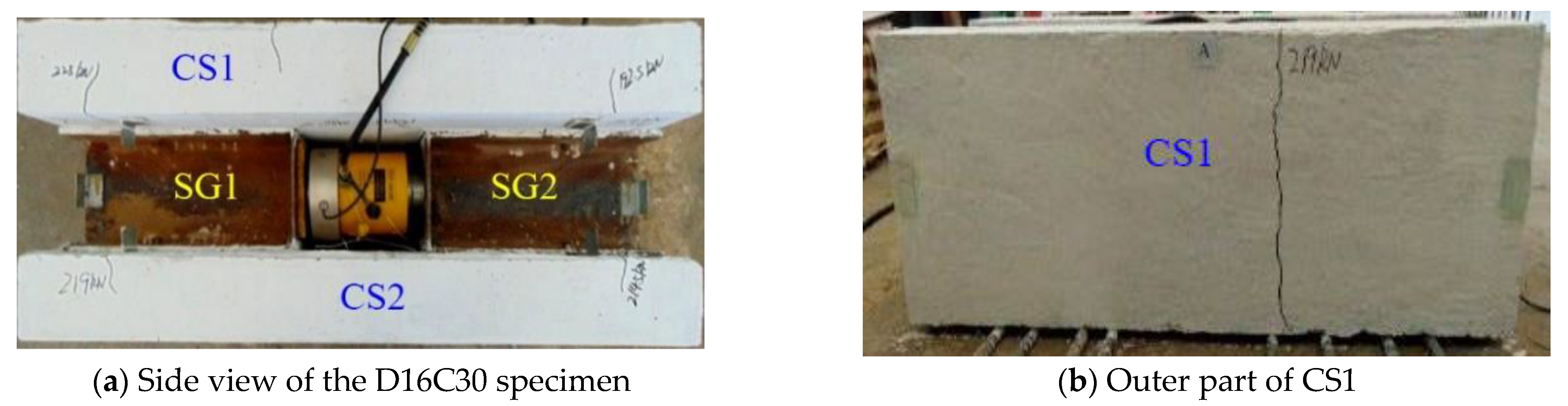
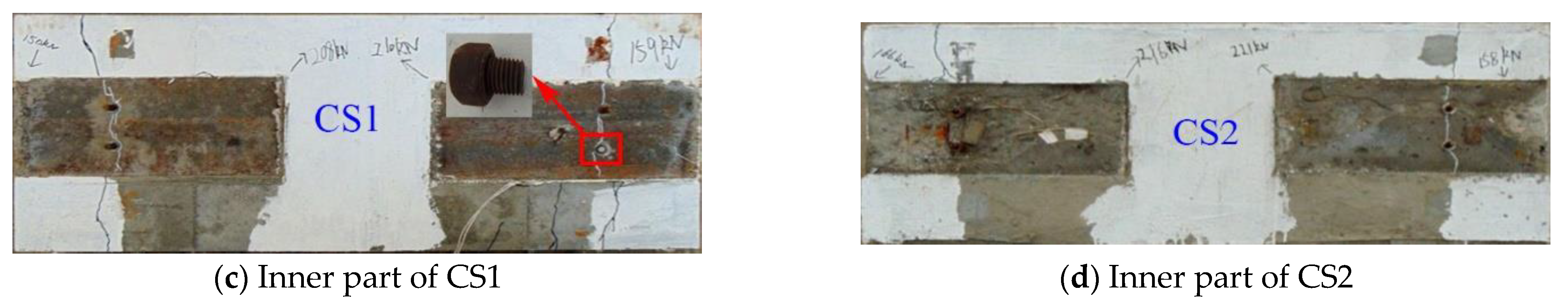
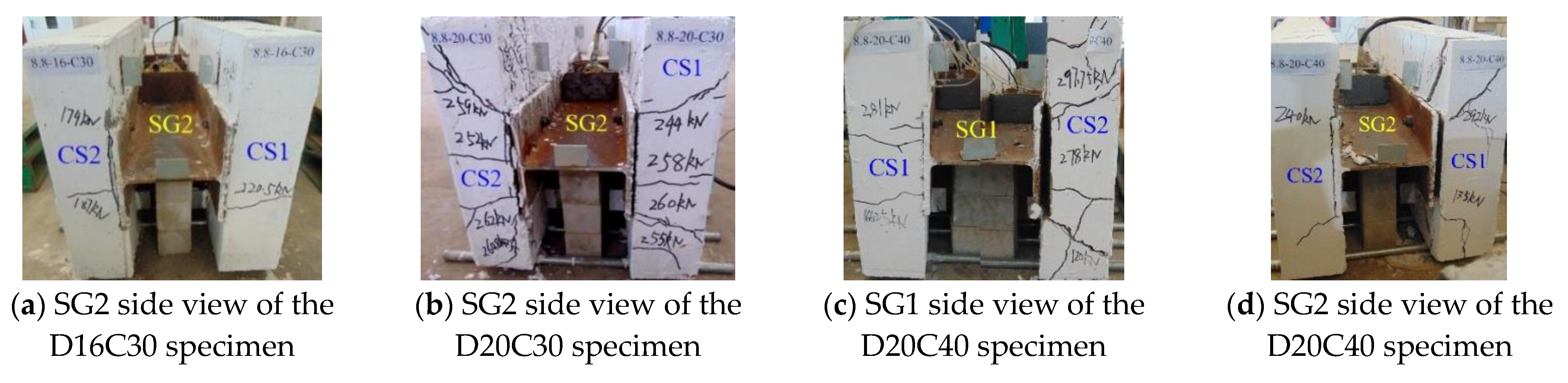
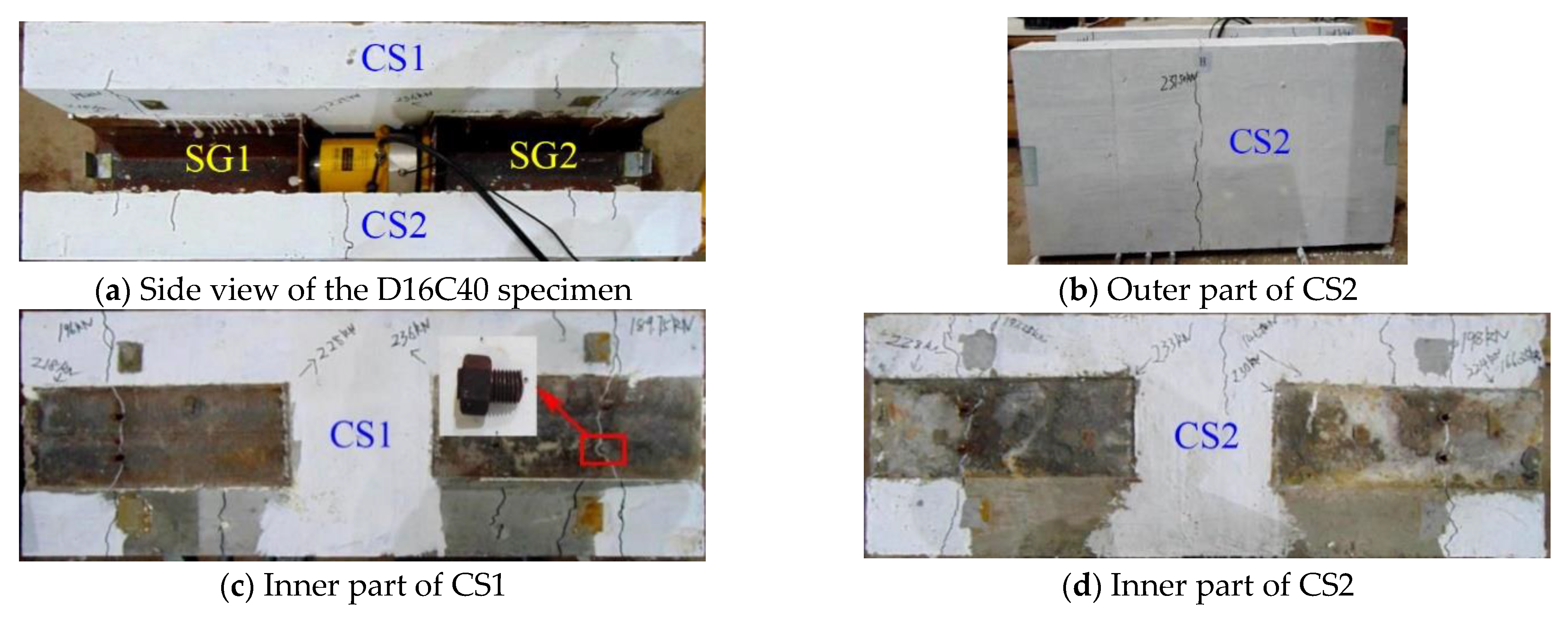
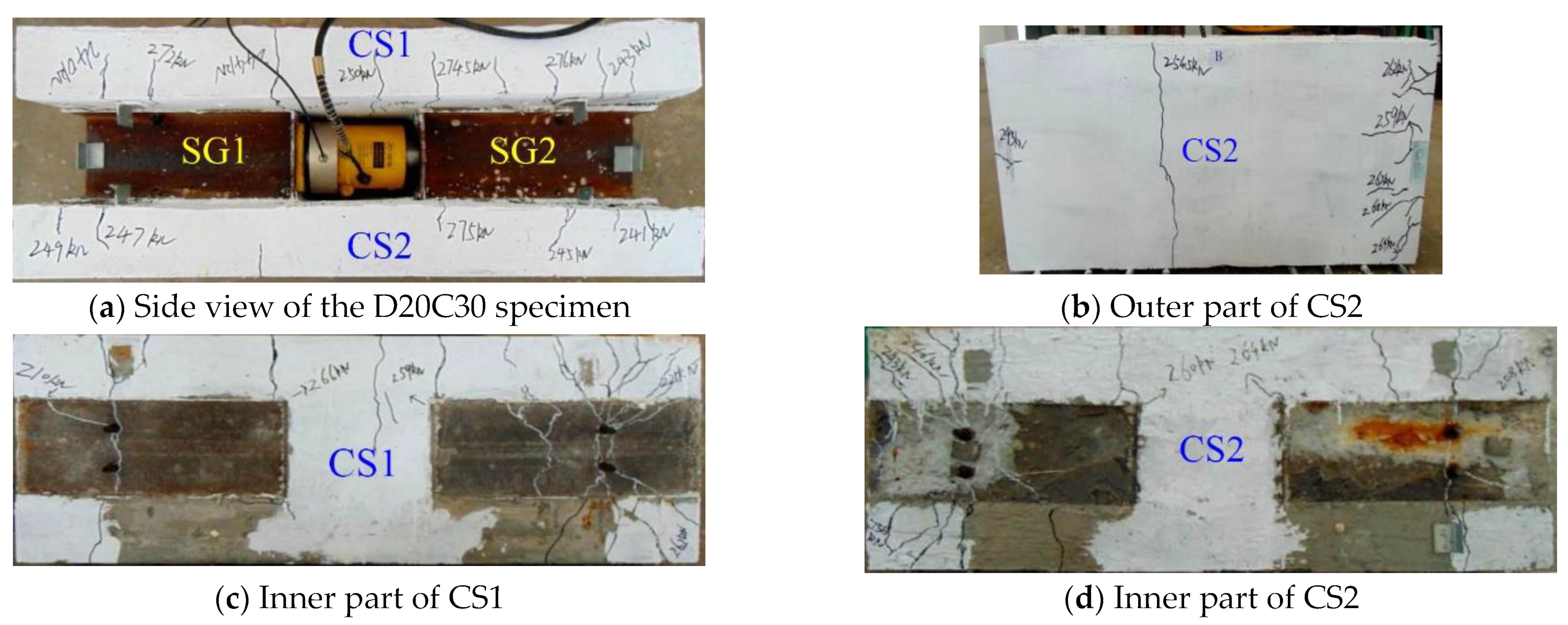
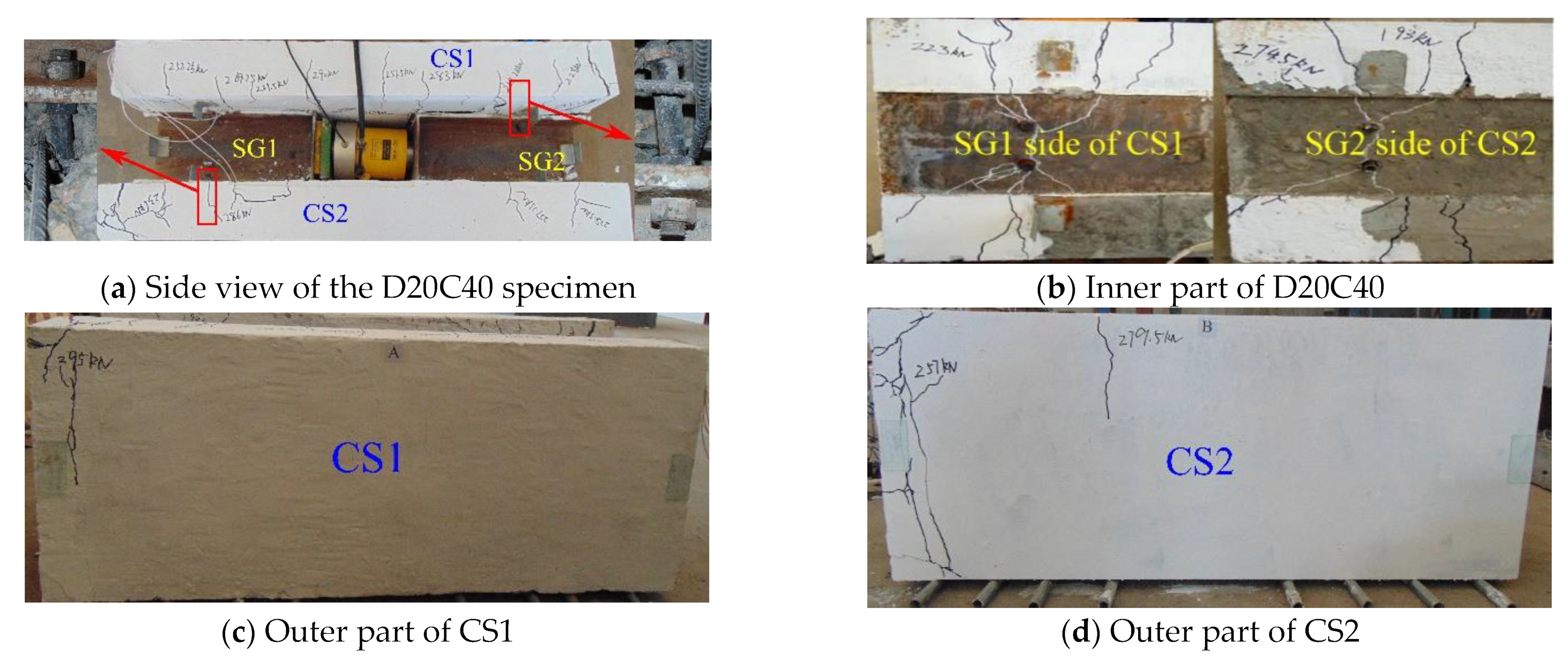
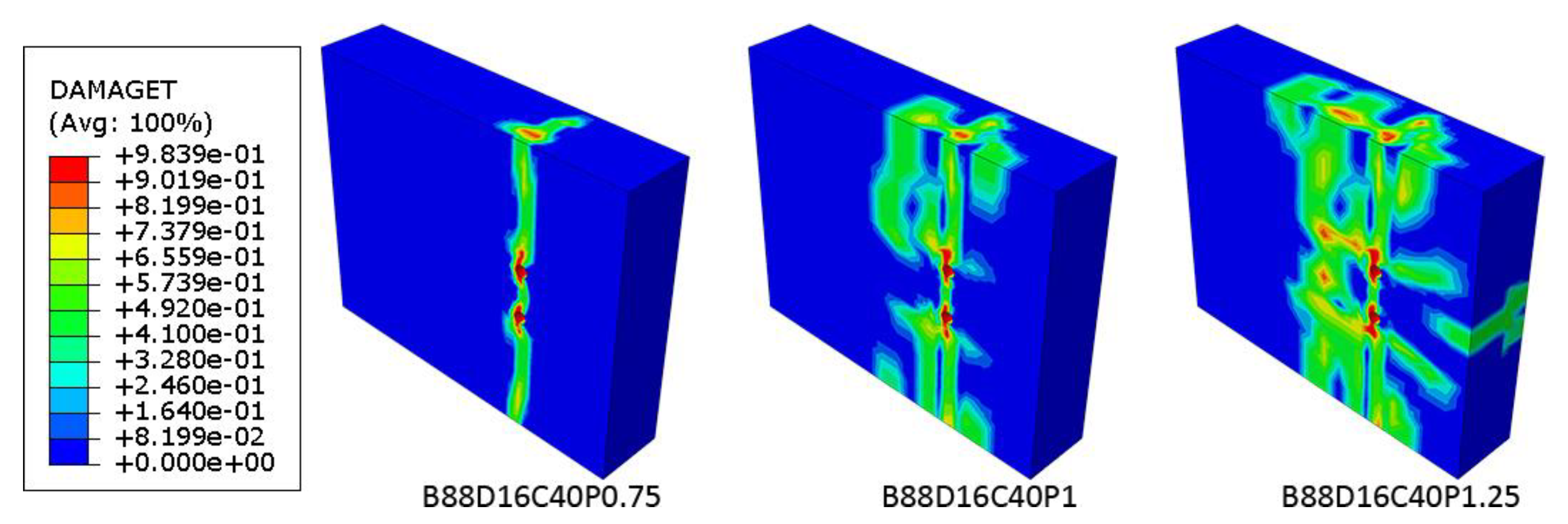
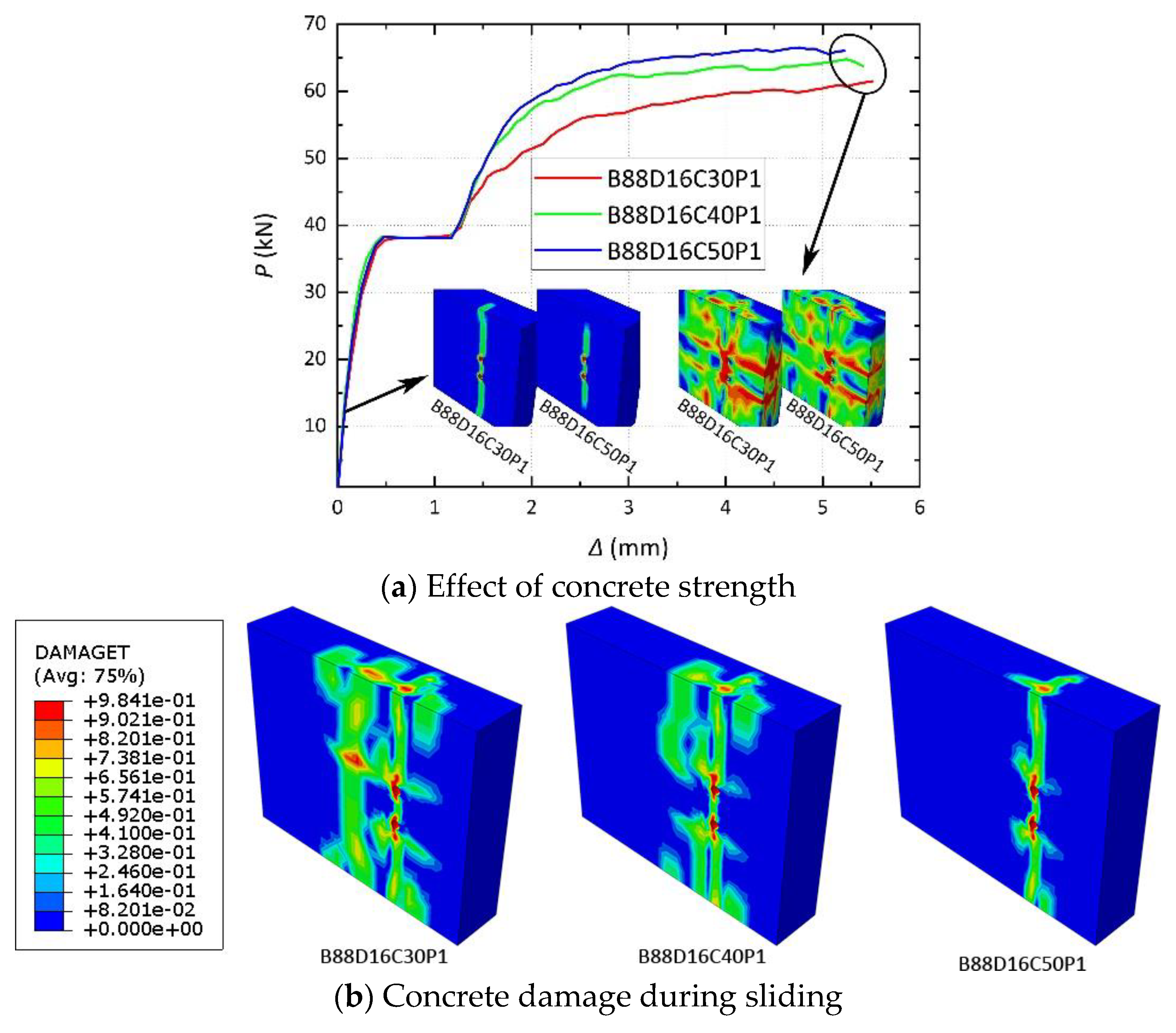
During the loading process, tensile and splitting cracks were produced in the concrete, the distribution of which became denser with decreasing concrete strength and increasing bolt diameter.
- (2)
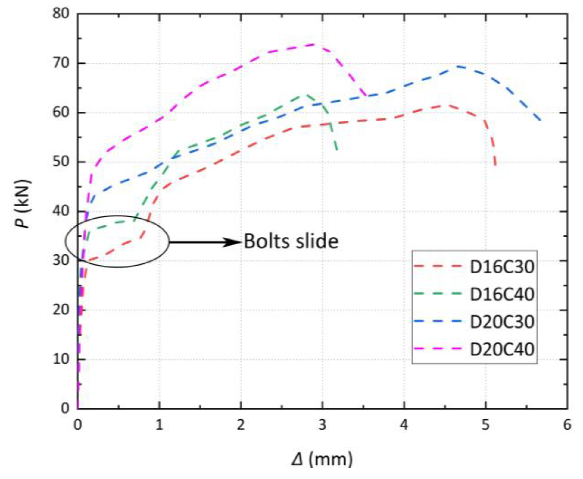
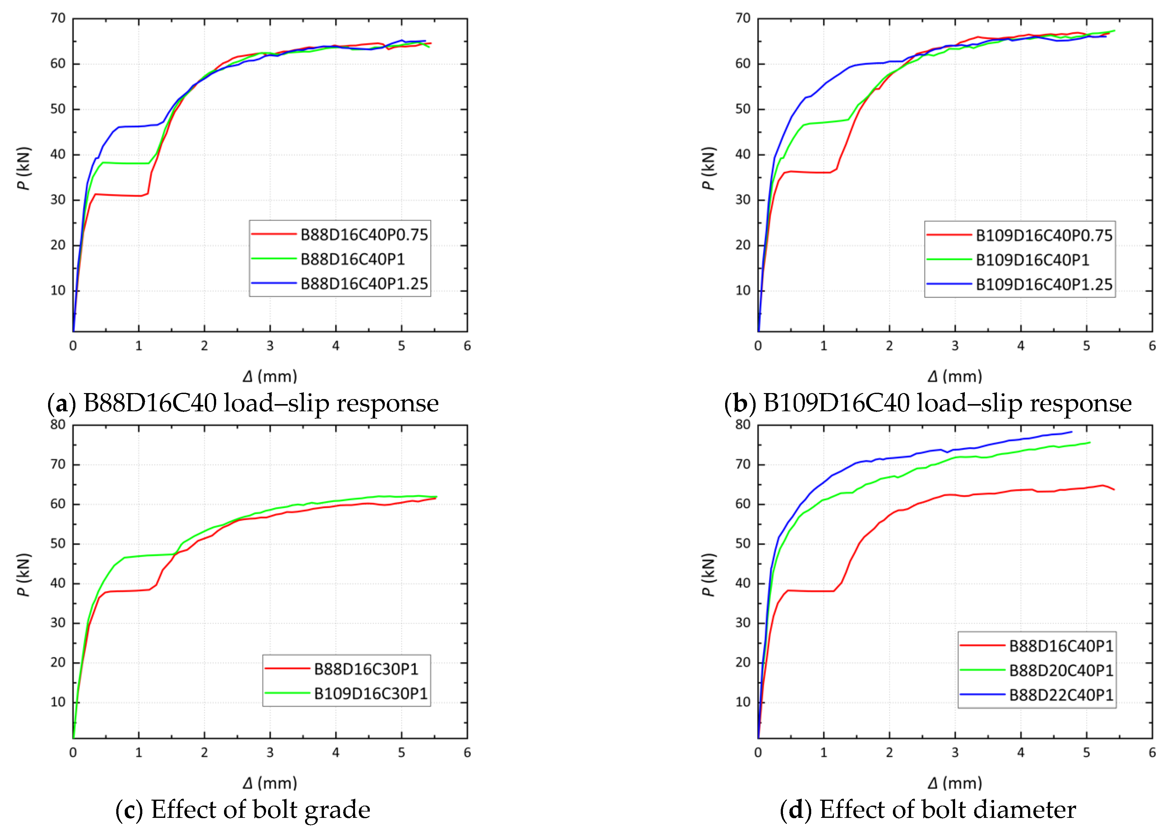
When the concrete strength increased from 30 to 40, the ultimate strength with 16 mm and 20 mm bolts increased by 3.6% and 6.2%, respectively.
- (3)
When the diameter of the bolts increased from 16 to 20 mm, the ultimate strength with C30 and C50 concrete increased by 12.8% and 15.6%, respectively.
- (4)
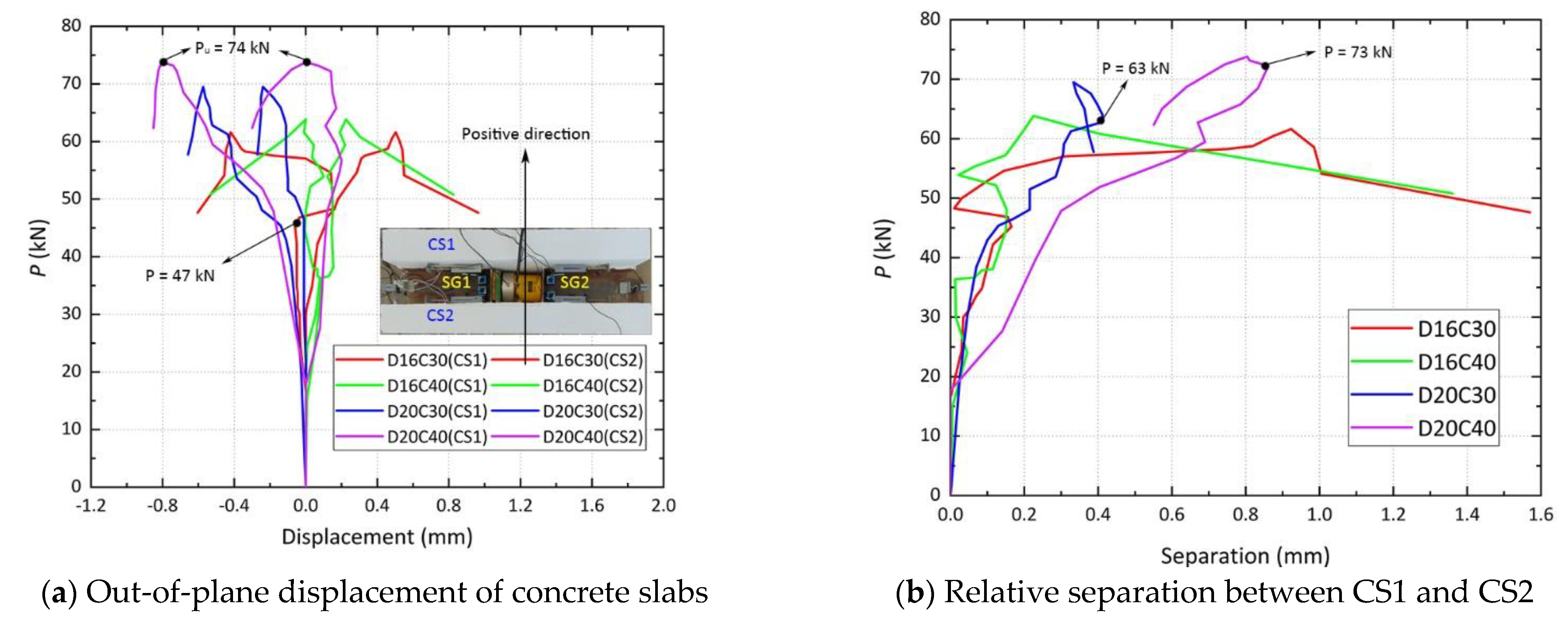
The concrete slabs tended to separate from each other, but this was mitigated when splitting cracks occurred.
The four specimens were modeled using ABAQUS and validated by comparing them with the experimental test results. The conclusions of the analysis are as follows:
- (1)
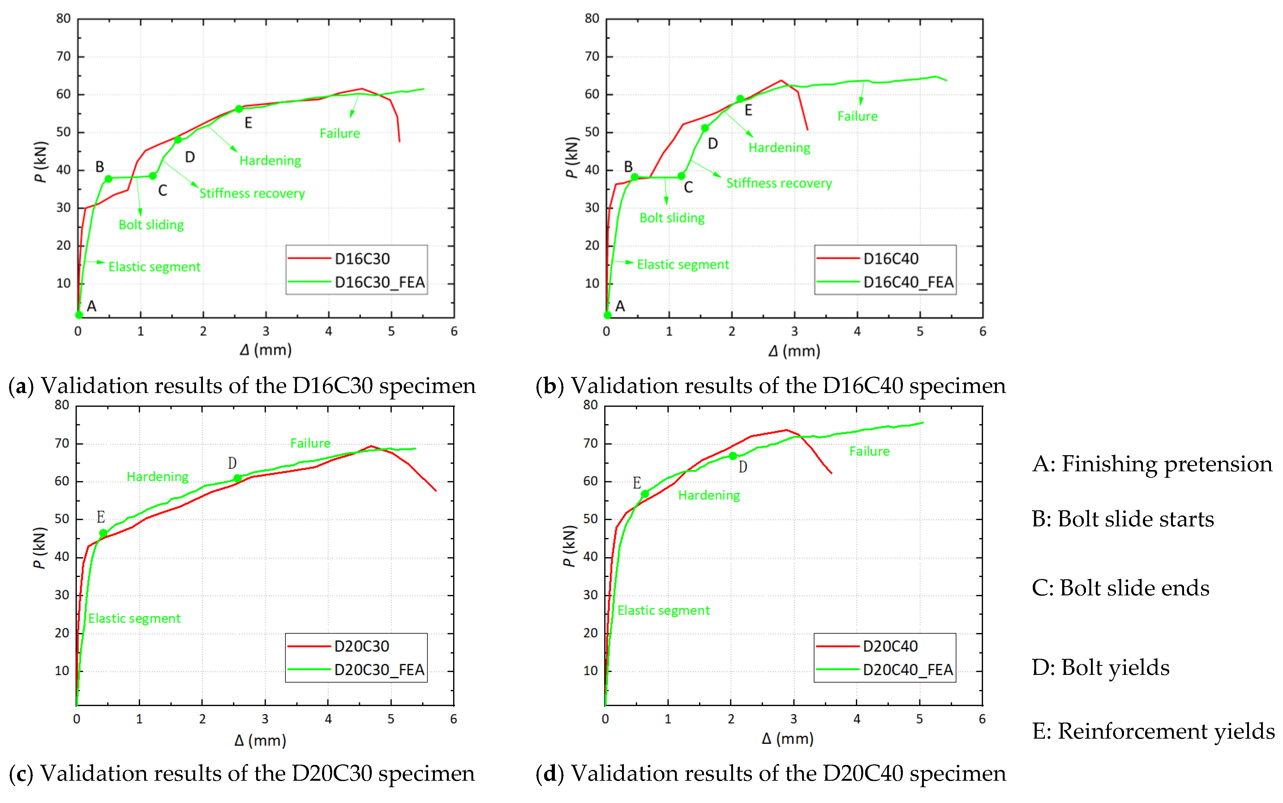
The load–slip responses of the specimens with 16 mm bolts could be divided into five phases, i.e., elastic segment, bolt sliding, stiffness recovery, hardening, and failure.
- (2)
The load–slip responses of the specimens with 20 mm bolts could be divided into three phases, i.e., elastic segment, hardening, and failure. The fact that bolt slip was not observed does not mean that it did not occur; instead, it occurred simultaneously with the concrete deformation and failure, rendering it difficult to be reflected in the load–slip response.
Based on the parametric analysis of 18 FE analysis models, an equation was proposed to calculate the shear capacity of high-strength bolted connectors to fill the evident gap in prior studies on the hogging moment.
When the research was applied to actual projects, the sliding characteristics of high-strength bolted connectors were effective in inhibiting concrete cracking in the hogging moment zone of steel–concrete composite beams.


