Article

Research on the Pressure Distribution Law of Synchronous Grouting in Shield Tunnels and the Force on Segments

1
College of Architectural Engineering, Tongling University, Tongling 244000, China
2
Civil Engineering Department, Hefei University, Hefei 230000, China
*
Author to whom correspondence should be addressed.
Buildings 2024, 14(4), 1099; https://doi.org/10.3390/buildings14041099
Submission received: 28 February 2024 / Revised: 10 April 2024 / Accepted: 12 April 2024 / Published: 15 April 2024
(This article belongs to the Special Issue Research on Underground Engineering and Geomechanics)

Abstract

:
The pressure distribution and the force on tunnel segments of synchronous grouting in the shield tail gap channel of shield tunnels are key to controlling the stability and surface settlement of the strata surrounding such tunnels. Based on the basic principles of fluid mechanics and the limit equilibrium method, this study establishes a mathematical model of synchronous grouting in shield tunnels, derives the expressions of the grouting pressure and the force on tunnel segments in the shield tail gap channel, and verifies them using an engineering case study. Studies have shown that the force on tunnel segments and the speed of shield excavation are increasing. An excessive shield excavation speed will cause the load on tunnel segments to increase, which exacerbates the uneven distribution of the grouting pressure. The force on tunnel segments and the grouting pressure also have a positive relationship with the thickness of the shield tail gap, but the impact is limited to a certain range. With an increase in the tunnel radius, the number of grouting holes should be appropriately increased to balance the water and soil pressure in the surrounding strata. These research results can provide a theoretical reference for the design of synchronous grouting for shield tunnels in the future.

1. Introduction

With the rapid development of China’s subway system, the control of the deformation of shields caused by the construction of various buildings is becoming more and more stringent [1,2,3,4]. The grouting behind walls is key to the construction of shield tunnels, and filling gaps in shields and reinforcing the soil can also cause a certain pressure on tunnel segments, which may cause them to be disturbed, the strata to be deformed, and surrounding buildings to be tilted [5,6,7,8]. The study of the mechanism of simultaneous grouting in shield tunnels and the analysis of the distribution patterns of the grouting pressure and influencing factors of the force on tunnel segments are of great significance for guiding the design of synchronous grouting for shield tunnels [9,10,11,12].
In recent years, experts and scholars in China and elsewhere have carried out much research on the mechanism of grouting behind the shield wall. Outside of China, Koyama, Y. (2003) found through a model test that, if it was too large or too small, the grouting pressure could cause an uneven distribution of soil pressure and disturb the surrounding strata [13]. Through the real-time monitoring of a spot, Bezuijen et al. (2004) analyzed the changes in the grouting pressure at different stages and found that it was gradually reduced over time [14]. Through a numerical simulation, Kasper et al. (2006) found that the grouting pressure distribution has a decisive effect on the deformation of strata and the load has a decisive effect on tunnel segments [15]. Koyama et al. (1998) conducted a large number of physical model tests on the grouting behind a shield tunnel wall to study the influence of grouting pressure on soil pressure [16]. In China, Zhang et al. (2015) explored the distribution pattern and dissipation process of slurry pressure in a shield tail gap, as well as the flow path and the diffusion pattern of a slurry, using a model test [17]. Liang et al. (2018) comprehensively considered the filling and diffusion of slurry during synchronous grouting, as well as the subsequent pressure dissipation caused by seepage, and they obtained a theoretical calculation formula for the longitudinal distribution of slurry pressure along the segment ring [18]. Qiu (2015) researched the process of the circular filling of the synchronous grouting of a shield tail with slurry, established a mechanical model of the grouting pressure, and analyzed the impacts of factors such as the shield tail gap on the distribution pattern of the slurry pressure [19]. Li Peinan et al. (2020) analyzed the diffusion mode mechanism of synchronous grouting in shield tunnels based on the Bingham fluid constitutive model and fluid mechanics principles and established a theoretical model of the longitudinal circumferential diffusion of synchronous grouting at the shield tail [20]. On the basis of existing research, Ye Fei et al. (2023) established a grouting compaction splitting diffusion model for shield tunnel walls in low-permeability strata by calculating the distribution of circumferential slurry pressure and the initial splitting pressure in shield tunnels [21]. The above research helps us to better understand the mechanism of grouting behind shield tunnel walls. However, the above theoretical model of synchronous grouting in shield tunnels only studied the distribution law of grouting pressure and did not consider the force on the tunnel segments. In fact, the force on the tunnel segment directly controls the deformation of the surrounding strata. When exploring the distribution law of grouting pressure, a theoretical analysis of the force on the tunnel segments is also necessary.
Based on previous findings, the basic principles of fluid mechanics, and the limit equilibrium method, we established a mathematical model of synchronous grouting in shield tunnels, derived the expressions of the grouting pressure and the force on tunnel segments in the shield tail gap channel, performed a contrastive analysis using the measured results, and verified the validity and reliability of the theory. Our focus was on the impacts of the speed of shield excavation, the thickness of the shield tail gap, and the radius of the shield tunnel on the grouting pressure and the impacts of the force on tunnel segments. This study intends to provide theoretical references for the design of synchronous grouting in shield tunnels.

2. The Mathematical Model of Synchronous Grouting in Shield Tunnels

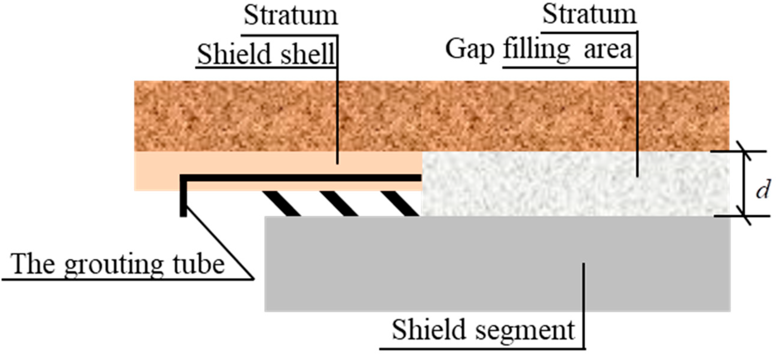
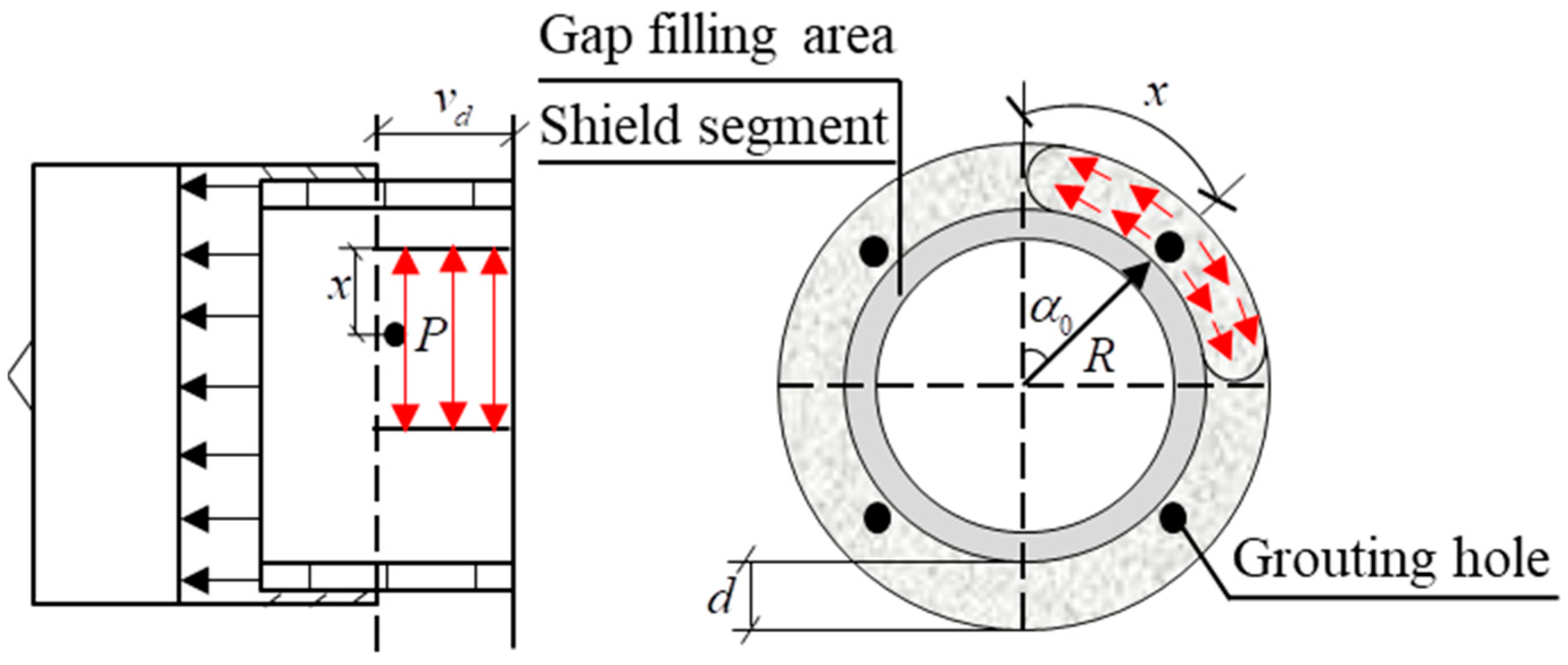
2.1. Synchronous Grouting

Synchronous grouting behind a shield tunnel wall is generally constructed with a grouting tube that is built into the shield shell. A sinking tube is implemented while the shield is excavated. The size and location of the grouting tube are set according to the needs of the project. The slurry gradually fills the shield tail gap generated by the shield under the grouting pressure, as shown in Figure 1.

2.2. Assumption

The process of synchronous grouting behind a shield tunnel wall involves hydraulically injecting grout into the gap at the tail of the shield through grouting pipes and holes that are installed on the segments while the shield is advancing and gradually filling the entire gap with grout. This process of filling and flow is a dynamic and complex process in space. In order to simplify its study, the formation and dissipation of slurry pressure within the thickness range of the shield tail gap are divided into two relatively independent stages. The first stage is the formation of the slurry pressure, which is mainly circularly spread along the tunnel; the second stage is the dissipation of the slurry pressure, which is mainly longitudinally spread along the tunnel. This study only analyzes the formation process of the slurry pressure in the cross-section of the shield tail gap. In order to build a pressure distribution model for synchronous grouting, the following assumptions are made:
(1)
The slurry is a non-compressed Bingham fluid and a monocomponent cement slurry;
(2)
The slurry exists only inside the gap channel, and its quality is not lost with the flow;
(3)
The boundary of the gap channel (the external border is the ground, and the inner boundary is the tunnel segment) does not experience slipping, and the slurry flow is laminar;
(4)
Only the radial speed of the slurry along the tunnel is considered, and the loss of speed of the slurry is not included.
Due to the relaxation of stress in a certain range of the surrounding soil caused by the gap at the shield tail, the displacement of the segment towards the outer wall occurs, resulting in the porosity of the soil mass in a certain range being far greater than the original porosity, thus greatly improving its permeability coefficient. A model of the diffusion of synchronous grouting behind a wall is shown in Figure 2: P is the grouting pressure, v d is the shield excavation speed, R is the radius of the tunnel segment, x is the diffusion distance for the slurry, α 0 is the angle between the position of the grouting hole and the shaft z , d is the thickness of the shield tail gap, and K is the injection rate. In the process of shield excavation, when the number of grouting holes is n and the shield excavation distance is v d t , the average shield tail gap volume that needs filling with a single grouting tube per unit of time is, theoretically, as follows:
V = π K ( d 2 + 2 R d ) v d n

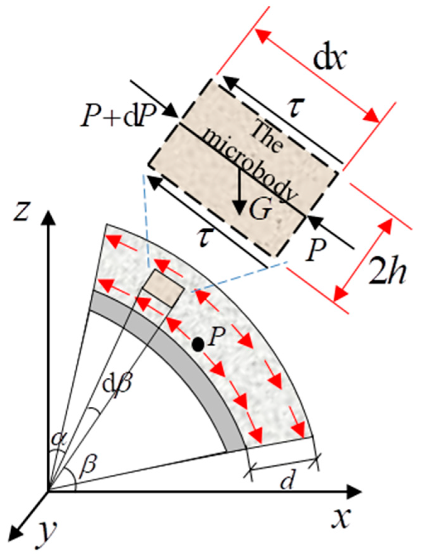
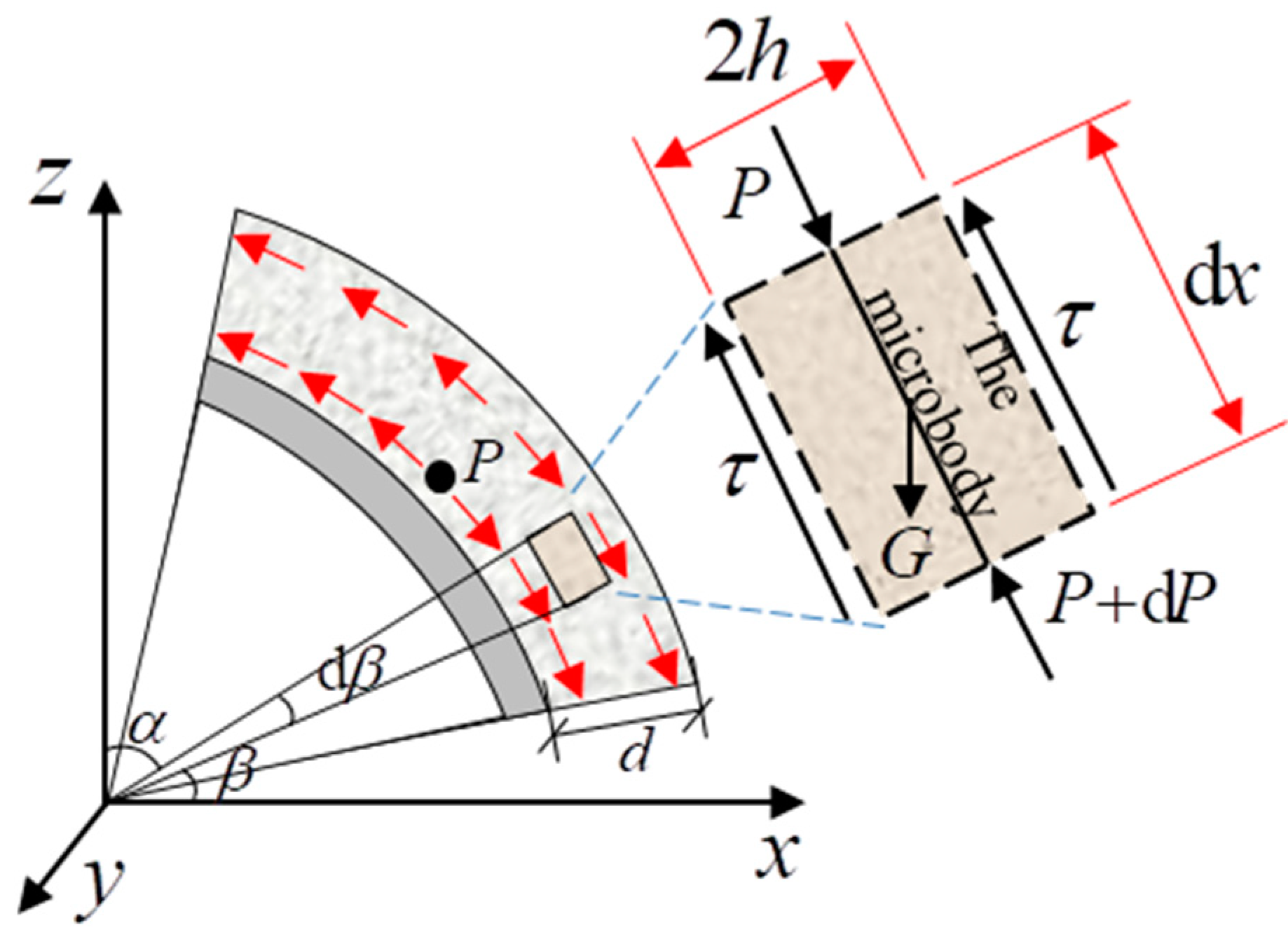
2.3. Synchronous Grouting Pressure Distribution Equation

When the slurry’s flow is that of a Bingham fluid, the shear force applied must be greater than the initial shear force so that the slurry can undergo a relative flow, and it shows a similarly solid nature. The form of its constitutive equation is as follows [22]:
τ = τ 0 + u γ = τ 0 + u ( d v d r )
In the equation, τ is the shear stress of the slurry, τ 0 is the initial shear stress, u is the plastic viscosity of the slurry, γ is the shear rate, v is the migration rate of the slurry, and r is the vertical distance in the direction of migration.
The slurry performs a laminar flow movement upwards in the shield tail gap channel. An analysis of the force on the microbody of the slurry is shown in Figure 3.
Due to the symmetry of the circular tunnel structure and the distribution of grouting holes, it can be considered that there is a symmetrical distribution of grouting pressure on both sides of the shaft z . The force on the microbody of the slurry is analyzed in the direction of the center line of the streamline as the symmetrical axis. The microbody undergoes laminar flow at the speed of v in the direction of the streamline’s center line; its surface is affected by the shear stress τ , whose direction is opposite to that of the flow velocity. The pressure on both ends is P + d P and P . α is the angle between the tunnel radius and the shaft z , and β is the angle between the tunnel radius and the shaft x ; then, d x = R d β . According to the stress balance of the microbody, the shear stress is as follows [23]:
τ = r ( d P R d β + ρ g cos β )
The following velocity gradient equation is derived from (2) and (3):
d v d r = r u ( d P R d β 3 τ 0 d + ρ g cos β )
When τ < τ 0 , there is a central stream nuclear area, the width of which is 2 h . When h r h , v = v ( r = ± h ) ; when r = ± d / 2 , v = 0 . Because the pressure gradient of the slurry is generally far greater than its initial shear stress, the small high-end item is ignored. The average flow rate of the slurry in the fracture section can be simplified as follows:
v ¯ = d 2 12 u ( d P R d β 3 τ 0 d + ρ g cos β )
According to the law of conservation of mass, the amount of grouting flowing upwards per unit of time q S is as follows:
q S = d v d v ¯ = v d d 3 12 u ( d P R d β 3 τ 0 d + ρ g cos β )
The variables in Equation (6) are separated; then, the pressure gradient of the slurry in the shield tail gap channel is as follows:
d P d β = 12 u R q S v d d 3 + 3 τ 0 R d R ρ g cos β
When x = x 0 (the grouting hole position), that is, β = β 0 , the slurry has not spread from the grouting hole. At this time, the grouting pressure is P 0 , and the distribution equation of the grouting pressure in the shield tail gap channel is as follows:
P ( β ) = P 0 + R ρ g ( sin π 4 sin β ) + 12 u R q S v d d 3 ( π 4 β ) + 3 τ 0 R d ( β π 4 )
In this equation, β 0 β β u , β 0 is the angle between the position of the grouting hole and the shaft x , and β u is the upward diffusion range of the grouting from the grouting hole.
Because the slurry performs an upward laminar flow movement, β is an angle rotating clockwise around the x axis. When β is replaced with α and β = π / 2 α , it can be seen that when grout moves upwards from the grouting holes, the grouting pressure is distributed as follows:
P 1 ( α ) = P 0 + R ρ g ( sin π 4 cos α ) + 12 u R q S v d d 3 ( α π 4 ) + 3 τ 0 R d ( π 4 α )
In this equation, α u α α 0 , α 0 is the angle between the position of the grouting hole and the shaft z , and α u is the upward diffusion range of the grouting from the grouting hole.
The slurry undergoes a downward laminar flow movement in the shield tail gap channel. An analysis of the force on the microbody of the slurry is shown in Figure 4.
This reasoning, which includes the upward flow of the slurry, has the following conclusions.
According to the law of conservation of mass, q X is the amount of grouting moving downward per unit of time, and the pressure distribution of the slurry in the shield tail gap channel when the slurry performs a downward laminar flow movement is as follows:
P 3 ( α ) = P 0 + R ρ g ( cos π 4 cos α ) + 12 u R q X v d d 3 ( π 4 α ) + 3 τ 0 R d ( α π 4 )
In this equation, α 0 α α d , α 0 is the angle between the position of the grouting hole and the shaft z , and α d is the downward diffusion range of the grouting from the grouting hole.

2.4. The Synchronous Grouting Pressure Distribution Calculation Model

In summary, according to Equations (9) and (10), the grouting pressure distribution can be extended to the case of porous grouting. When the typical four-hole grouting method is adopted, the calculation model for the grouting slurry pressure distribution is as follows.
When the grouting holes are located at α 0 = π / 4 , the slurry has not spread from them. At this time, the grouting pressure is P 0 , and the distribution equation of the grouting pressure in the shield tail gap channel is as follows:
P 1 ( α ) = P 0 + R ρ g ( sin π 4 cos α ) + 12 u R q S v d d 3 ( α π 4 ) + 3 τ 0 R d ( π 4 α ) ( 0 α π 4 )
P 3 ( α ) = P 0 + R ρ g ( cos π 4 cos α ) + 12 u R q X v d d 3 ( π 4 α ) + 3 τ 0 R d ( α π 4 ) ( π 4 α π 2 )
When the grouting holes are located at α 0 = 3 π / 4 , the slurry has not spread from them. At this time, the grouting pressure is P 0 , and the distribution equation of the grouting pressure in the shield tail gap channel is as follows:
P 2 ( α ) = P 0 R ρ g ( cos π 4 + cos α ) + 12 u R q S v d d 3 ( α 3 π 4 ) + 3 τ 0 R d ( 3 π 4 α ) ( π 2 α 3 π 4 )
P 4 ( α ) = P 0 R ρ g ( sin π 4 + cos α ) + 12 u R q X v d d 3 ( 3 π 4 α ) + 3 τ 0 R d ( α 3 π 4 ) ( 3 π 4 α π )

2.5. The Stress of Shield Tunnel Segments in the Gap Channel at the Tail of the Shield

Since Equations (11)–(14) make up the calculation model for the synchronous grouting pressure distribution, the force generated by the slurry on the tunnel segment is as follows:
F = 2 ( 0 π 4 P 1 ( α ) v d R d α + π 4 π 2 P 3 ( α ) v d R d α + π 2 3 π 4 P 2 ( α ) v d R d α + 3 π 4 π P 4 ( α ) v d R d α )
Equations (11)–(14) are integrated into Equation (15), and it can be shown that the force generated by the slurry on the tunnel segment is as follows:
F = v d R ( P 0 + P 0 ) + 4 v d R 2 ρ g 3 π 2 u R 2 2 d 3 ( q S + q X ) + 3 π 2 τ 0 v d R 2 16 d
In Equation (1), it can be seen that when the four-hole grouting method is used, the amount of grouting q of a single grouting hole per unit of time is as follows:
q = π K ( d 2 + 2 R d ) v d 4
The amount of grouting q S of a single grouting hole per unit of time and the amount of downward-moving grouting q X are q = q S + q X . Equation (17) is integrated into Equation (16), and the following expression of the force on the tunnel segments per unit of time is obtained:
F = v d R ( P 0 + P 0 ) + 4 v d R 2 ρ g 3 π 3 u K R 2 v d 8 d 2 ( d + 2 R ) + 3 π 2 τ 0 v d R 2 16 d
Equation (18) is the expression for the force exerted by the shield tunnel slurry on the tunnel segments. From this, we can see that the pressure distribution of the synchronous grouting in the shield tunnel and the force on the tunnel segments are related to many factors, such as the grouting pressure, slurry performance, thickness of the shield tail gap, shield excavation speed, and outer radius of the tunnel segments.

3. Engineering Case Study

3.1. Example Verification

The parameters related to the construction of shields for a subway tunnel in Shanghai are shown in the table below [19].
In the table, R is the outer radius of the tunnel segments, d is the thickness of the shield tail gap, v d is the shield excavation speed, n is the number of grouting holes, and the grouting method is four-hole grouting. P 0 is the downward-moving grouting pressure, P 0 is the upward-moving grouting pressure, ρ is the slurry density, u is the plastic viscosity, τ 0 is the initial shear stress, K is the injection rate, q S is the amount of upward-moving grouting, and q X is the amount of downward-moving grouting.
The above parameters are integrated into Equations (11)–(14), and the specific pressure distribution of the slurry in the shield tail gap is shown in Figure 5. The measured and theoretical values of the slurry pressure on the tunnel vault, arch bottom, and two arch waists are shown in Table 1.
An analysis of the graph and table shows the following:
(1)
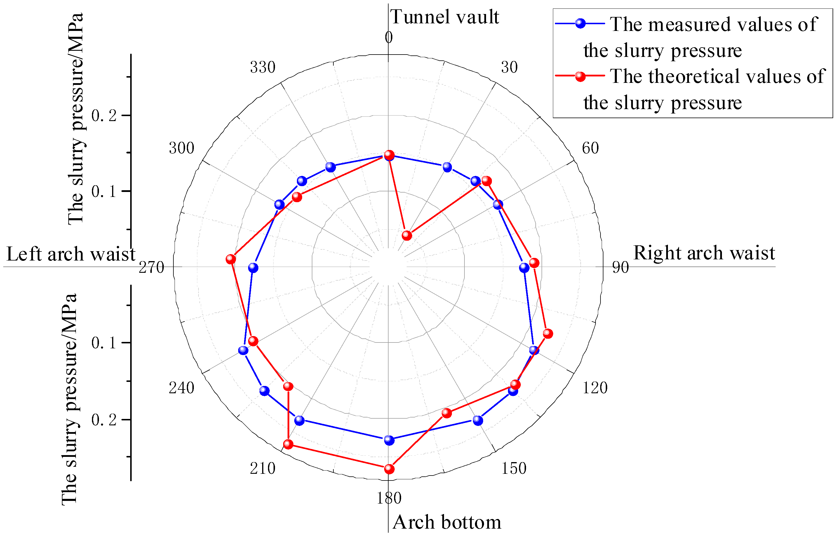
In Figure 5, it can be observed that the theoretical calculation of the slurry pressure is basically consistent with the measured growth trend of the slurry pressure, and the slurry pressure shows a nonlinear increasing distribution from the arch top to the arch bottom. This is because when the slurry is filled in an upward direction, gravity performs negative work, while when it is filled in a downward direction, gravity performs positive work.
(2)
Through the comparison in Table 2, it was found that the theoretical and measured values of the slurry pressure at the tunnel arch crown, arch bottom, and two arch waists were 98.6%, 94.5%, 92.7%, and 101.1%, respectively. The error between the theoretical calculation results and the measured pressure on site did not exceed 10%, and the error was still within the allowable range of the project. Therefore, the theoretical model of synchronous grouting in shield tunnels in this study can effectively guide the design and construction of on-site shield tunnel grouting.

3.2. Analysis of Influencing Factors

Based on the aforementioned theory, this section mainly analyzes the impacts of the thickness of the shield tail gap, the shield excavation speed, and the radius of the shield tunnel on the grouting pressure and the impacts of the force on tunnel segments. The values of the grouting parameters used are shown in Table 3.

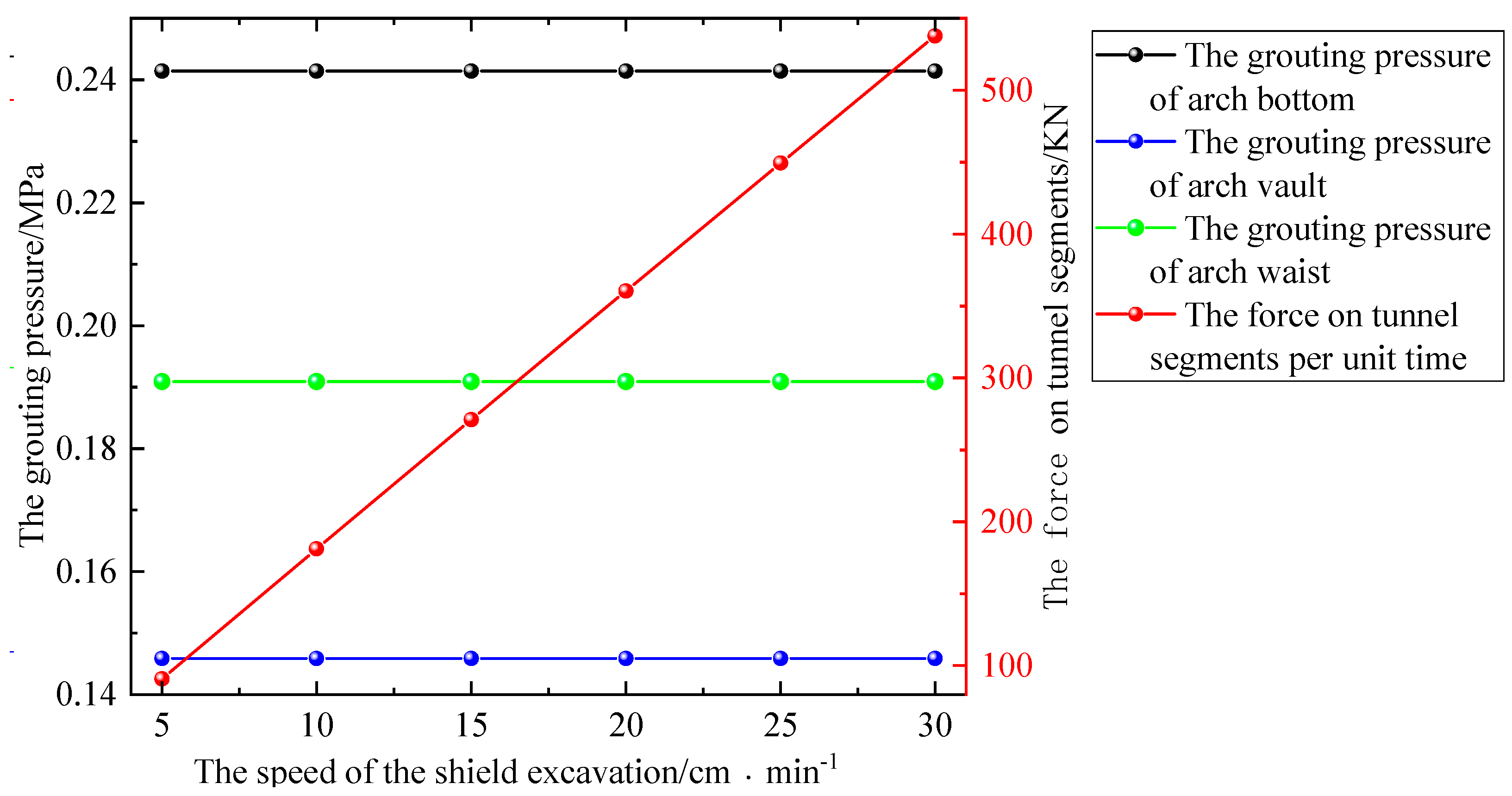
3.2.1. The Shield Excavation Speed

The impacts of the shield excavation speed on the grouting pressure and the force on tunnel segments when the shield excavation speed v d is 5, 10, 15, 20, 25, and 30 cm·min−1 are as shown in Figure 6.
According to the analysis in Figure 6, as the speed of the shield excavation increases, the grouting pressure in the shield tail gap remains unchanged, but the force on the tunnel segments per unit of time linearly increases, and the growth trend is obvious. For example, when the shield excavation speed increases from 5 cm·min−1 to 30 cm·min−1, the force on the tunnel segments increases from 90.89 kN to 537.73 kN, an increase of 446.84 kN.
In the process of the construction of synchronous grouting in a shield tunnel, the speed of shield excavation is closely related to the grouting rate. An excessive speed of shield excavation will lead to an increase in the amount of grouting and an uneven distribution of the grouting pressure; it can also increase the load on tunnel segments, resulting in the occurrence of slurry overflow and the deformation of strata. Therefore, the speed of shield excavation should be strictly controlled.

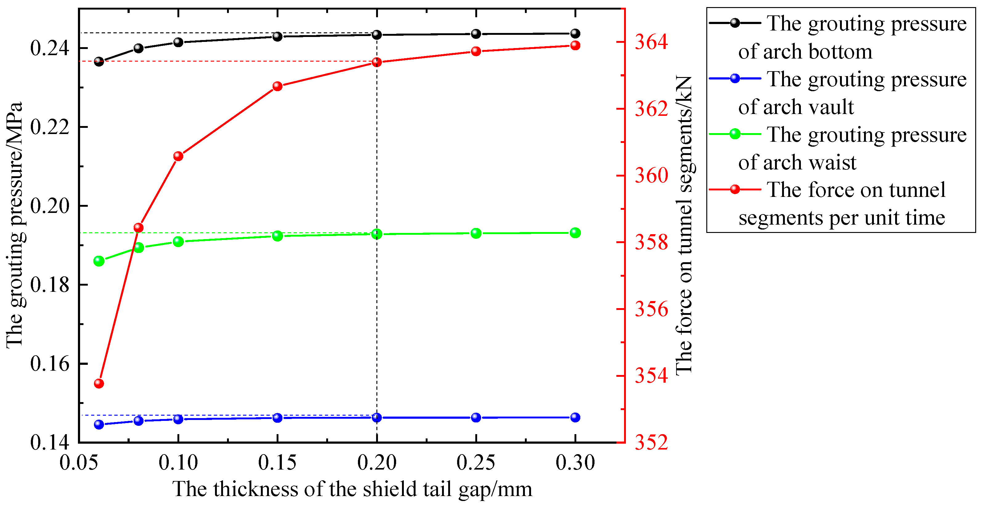
3.2.2. The Thickness of the Shield Tail Gap

In order to study the effects of the thickness of the shield tail gap d on the grouting pressure distribution and the force on tunnel segments, this study used values of 0.06, 0.08, 0.1, 0.15, 0.2, 0.25, and 0.3 m. The results are shown in Figure 7.
According to the analysis in Figure 7, it can be observed that as the thickness of the shield tail gap increases, the amount of slurry filling increases, and the force on the segment per unit of time also increases. However, once the thickness surpasses a certain threshold, the pressure stabilizes. For example, when the thickness increases from 0.06 m to 0.2 m, the force on the tunnel segments rises from 353.76 kN to 363.39 kN. Beyond a thickness of 0.2 m, the force remains relatively stable at 363.50 kN. This trend is also evident in the grouting pressure within the shield tail gap, including the arch vault, arch bottom, and arch waist. However, the impact of the thickness on the grouting pressure is limited to the range of 0.2 m.
During the actual excavation and construction of a shield, deviations between the actual and theoretical thickness of the shield tail gap may occur due to factors such as excessive excavation, correction, or turning. Consequently, the actual grouting volume in soft soil areas can exceed the theoretical grouting volume. Therefore, it is crucial to control the thickness of the shield tail gap within reasonable limits. This helps to prevent issues such as excessive grouting pressure, which can cause the ground surface to rise, resulting in undue force on tunnel segments.

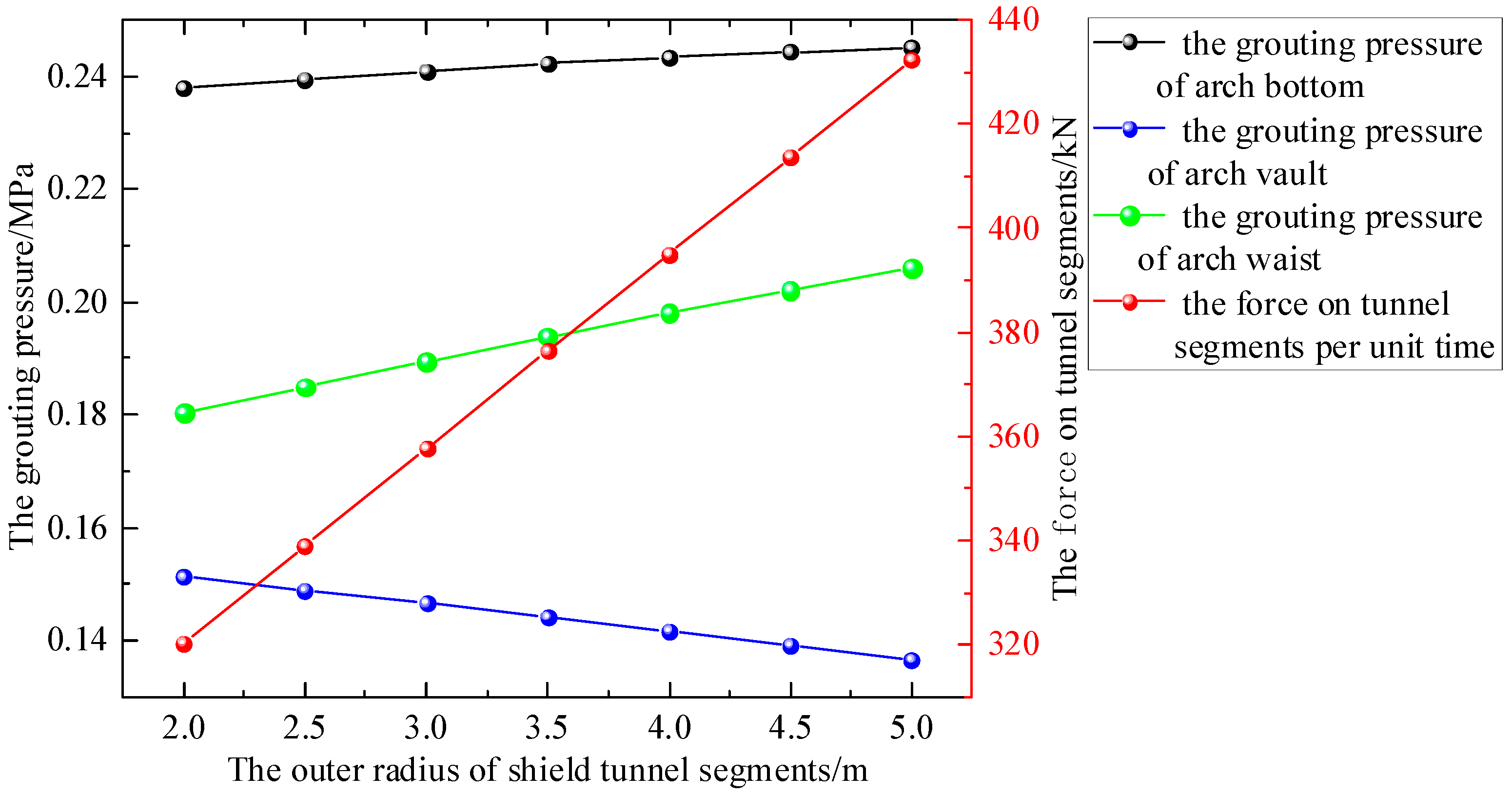
3.2.3. The Radius of the Shield Tunnel

The influence of the shield tunnel radius on the grouting pressure and the force on tunnel segments is shown in Figure 8; we use values of 2, 2.5, 3, 3.5, 4, 4.5, and 5 m.
Based on the analysis presented in Figure 8, it is evident that an increase in the radius of the shield tunnel leads to a proportional linear increase in the force on the tunnel segment per unit of time. This growth trend becomes more pronounced as the radius increases. For instance, when the outer radius of the shield tunnel segment expands from 2 m to 5 m, the segment force rises from 320.35 kN to 432.35 kN, indicating an increase of 112.00 kN. Additionally, as the tunnel radius increases, the slurry pressure at different sections of the arch undergoes changes. The slurry pressure decreases at the top of the arch while it increases at the bottom and waist of the arch. When the outer radius of the tunnel segment increases from 2 m to 5 m, the grouting pressure at the top of the arch is reduced from 0.1513 MPa to 0.1365 MPa, reflecting a decrease of 0.0148 MPa. Conversely, the grouting pressure at the arch bottom increases from 0.2379 MPa to 0.2451 MPa, showing an increase of 0.0072 MPa. The reason for the relatively small increase in grouting pressure at the bottom of the arch is that when the slurry is filled upwards, both the viscous force and gravity perform negative work. However, when filling downwards, gravity performs positive work, although the viscous force continues to perform negative work.
From these observations, it becomes apparent that as the tunnel radius increases, the slurry-filling path within the gap at the shield tail also expands. Using only four holes for grouting leads to a significant deficiency in the slurry-filling rate at the top of the arch, while the slurry pressure at the bottom of the arch becomes excessively high, thereby failing to effectively balance the water and soil pressure of the surrounding strata. Consequently, instability in the strata occurs. This is why large-diameter shield tunnels typically employ six or even eight holes for grouting purposes.

4. Conclusions

Based on the movement of slurry as a Bingham fluid, this study established a mathematical model of synchronous grouting in shield tunnels, derived the expression of the grouting pressure and the force on tunnel segments in the shield tail gap channel, and verified the model using an engineering case study.
The speed of shield excavation is closely related to the grouting rate. An excessive speed of shield excavation will lead to an increase in the amount of grouting and an uneven distribution of the grouting pressure; it can also increase the load on tunnel segments, resulting in the occurrence of slurry overflow and the deformation of strata. Therefore, the speed of shield excavation should be strictly controlled.
In the process of the actual excavation and construction of shields, the thickness of the shield tail gap should be reasonably controlled to avoid increasing the thickness due to excessive excavation, correction, and turning, thus causing an increase in the grouting pressure and force on tunnel segments.
When the radius of the tunnel increases to a certain extent, the filling path of the slurry in the gap at the tail of the shield increases accordingly. Four-hole grouting causes a serious shortage in the slurry filling rate at the top of the shield, and six-hole grouting or eight-hole grouting must be used to meet the filling requirements at the arch crown.

5. Shortcomings and Prospects

On the basis of previous research, this article optimizes the mathematical model of and analyzes the relationship between shield tunneling speed and grouting pressure. At the same time, we focused on studying the relationship between the force on tunnel segments and the speed and radius of shield tunneling. However, the established mathematical model did not consider the mud filtration effect. In subsequent research, it is necessary to simultaneously consider the time-varying viscosity of the slurry and the filtration effect of the slurry in order to establish a more realistic mathematical model.

Author Contributions

Writing—original draft, Y.C.; Formal analysis, Y.C.; Investigation, Y.C.; Data curation, Y.C.; Writing—review & editing, X.L.; Funding acquisition, X.L.; Supervision, X.L. All authors have read and agreed to the published version of the manuscript.

Funding

This study was supported by the Anhui Provincial Department of Education Natural Science Fund Key Project (KJ2021A1056, 2023AH052181) and the Talent Research Fund Project of Hefei University (23RC19).

Data Availability Statement

The raw data supporting the conclusions of this article will be made available by the authors on request.

Conflicts of Interest

The authors declare that there are no conflicts of interest regarding the publication of this paper.

References

  1. Liu, X.; Shen, S.; Xu, Y.; Zhou, A. Non-linear spring model for backfill grout-consolidation behind shield tunnel lining. Comput. Geotech. 2021, 136, 104235. [Google Scholar] [CrossRef]
  2. Ye, F.; Wang, B.; Han, X.; Liang, X.; Ying, K.; Liang, X. Review of shield tunnel backfill grouting tests and its diffusion mechanism. China J. Highw. Transp. 2020, 33, 92–104. [Google Scholar]
  3. Zhu, H.; Ding, W.; Qiao, Y.; Xie, D. Micro-disturbed construction control technology system for shield driven tunnels and its application. Chin. J. Geotech. Eng. 2014, 36, 1983–1993. [Google Scholar]
  4. Ye, F.; Xia, T.; Ying, K.; Li, Y.; Liang, X.; Han, X. Optimization method for backfill grouting of shield tunnel based on stratum suitability characteristics. Chin. J. Geotech. Eng. 2022, 44, 2225–2233. [Google Scholar]
  5. Liang, Y.; Yang, J.; Wang, S.; Zeng, X. A study on grout consolidation and dissipation mechanism during shield backfilled grouting with considering time effect. Rock Soil Mech. 2015, 36, 3373–3380. [Google Scholar]
  6. Ye, F.; Yang, T.; Mao, J.; Qin, X.; Zhao, R. Half-spherical surface diffusion model of shield tunnel back-fill grouting based on infiltration effect. Tunn. Undergr. Space Technol. 2019, 83, 274–281. [Google Scholar] [CrossRef]
  7. Tang, M.; Chen, R.; Chen, W. Stress monitoring and internal force analysis of Guangzhou metro shield tunnel segment during construction. China Civ. Eng. J. 2009, 42, 118–124. [Google Scholar]
  8. Liang, Y.; Zhang, J.; Lai, Z.; Huang, Q.; Huang, L. Temporal and spatial distribution of the grout pressure and its effects on lining segments during synchronous grouting in shield tunnelling. Eur. J. Environ. Civ. Eng. 2020, 24, 79–96. [Google Scholar] [CrossRef]
  9. Ye, F.; Mao, J.; Ji, M.; Sun, C.; Chen, Z. Research status and development trend of back-filled grouting of shield tunnels. Tunn. Constr. 2015, 35, 739–752. [Google Scholar]
  10. Ma, J.; Sun, A.; Jiang, A.; Guo, N.; Liu, X.; Song, J.; Liu, T. Pressure Model Study on Synchronous Grouting in Shield Tunnels Considering the Temporal Variation in Grout Viscosity. Appl. Sci. 2023, 13, 10437. [Google Scholar] [CrossRef]
  11. Wen, D.; Chao, D.; Yao, Z. The behavior of synchronous grouting in a quasi-rectangular shield tunnel based on a large visualized model test. Tunn. Undergr. Space Technol. 2019, 83, 409–424. [Google Scholar]
  12. Qiu, M.; Jiang, A. Backfill grout pressure distribution model for a metro shield tunnel. Mod. Tunn. Technol. 2013, 50, 115–121. [Google Scholar]
  13. Koyama, Y. Present status and technology of shield tunneling method in Japan. Tunn. Undergr. Space Technol. Inc. Trenchless Technol. Res. 2003, 18, 145–159. [Google Scholar] [CrossRef]
  14. Bezuijen, A.; Talmon, A.; Kaalberg, F.; Plugge, R. Field measurements of grout pressures during tunnelling of the Sophia Rail Tunnel. Soils Found. 2004, 44, 39–48. [Google Scholar] [CrossRef]
  15. Kasper, T.; Meschke, G. On the influence of face pressure, grouting pressure and TBM design in soft ground tunneling. Tunn. Undergr. Space Technol. 2006, 21, 160–171. [Google Scholar] [CrossRef]
  16. Koyama, Y.; Sato, Y.; Okano, N. Back-fill Grouting Model Test for Shield Tunnel. Q. Rep. RTRI 1998, 39, 35–39. [Google Scholar]
  17. Zhang, S.; Dai, Z.; Bai, Y. Model Test Research on distribution law of grout pressure for simultaneous backfill grouting during shield tunneling. China Railw. Sci. 2015, 36, 43–53. [Google Scholar]
  18. Liang, Y.; Huang, L. Grout pressure distribution characteristic in space-time domain of shield tunnels during synchronous grouting. J. Harbin Inst. Technol. 2018, 50, 165–170. [Google Scholar]
  19. Qiu, M.; Yang, G.; Jiang, A. Influence factors and pressure distribution of simultaneous grouting for shield tunnel. J. Shenzhen Univ. (Sci. Eng.) 2015, 32, 162–171. [Google Scholar] [CrossRef]
  20. Li, P.; Shi, L.; Li, X.; Liu, J. Theoretical model of longitudinal circumferential diffusion of synchronous grouting in shield tunnels. J. Tongji Univ. (Nat. Sci. Ed.) 2020, 48, 629–637. [Google Scholar]
  21. Ye, F.; Li, S.; Xia, T.; Su, N.; Han, X.; Zhang, C. Study on the grouting compaction splitting diffusion model behind the wall of shield tunnels in low permeability strata. J. Geotech. Eng. 2023, 45, 2014–2022. [Google Scholar]
  22. Cheng, H.; Liu, X.; Lin, J.; Zhang, L.; Li, M.; Rong, C. Study on fracturing and diffusion mechanism of non-slab fracturing grouting. Geofluids 2020, 2020, 1–9. [Google Scholar]
  23. Liu, X.; Cheng, H.; Li, M.; Wang, X.; Zhang, L.; Zhou, R. Theoretical research on longitudinal fracture grouting of deep buried strata based on slurry rheology. Rock Soil Mech. 2021, 42, 1373–1380+1394. [Google Scholar]
Figure 1. A diagram of synchronous grouting behind a wall.
Buildings 14 01099 g001
Figure 2. Synchronous grouting and model of penetrating diffusion behind a wall.
Buildings 14 01099 g002
Figure 3. Analysis of the force on the microbody of a slurry for the upwards movement.
Buildings 14 01099 g003
Figure 4. Analysis of the force on the microbody of a slurry for the downwards movement.
Buildings 14 01099 g004
Figure 5. Pressure distribution curve of the slurry in the shield tail gap.
Buildings 14 01099 g005
Figure 6. The influence of the shield excavation speed on the grouting pressure and tunnel segment stress.
Buildings 14 01099 g006
Figure 7. The influence of the shield tail gap’s thickness on the grouting pressure and tunnel segment stress.
Buildings 14 01099 g007
Figure 8. The influence of the shield tunnel radius on the grouting pressure and tunnel segment stress.
Buildings 14 01099 g008
Table 1. The parameters related to the construction of shields for a subway tunnel in Shanghai.
Parameter R d v d n P 0 P 0
Value3100 mm100 mm20 cm·min−140.16 MPa0.23 MPa
Parameter ρ u τ 0 K q S q X
Value1500 kg/m30.09 Pa·s9 Pa1.51.24 × 10−4 m3/s3.71 × 10−4 m3/s
Table 2. Measured and theoretical values of the slurry pressure.
LocationTunnel VaultArch BottomLeft Arch WaistRight Arch Waist
Measured value [19]0.148 MPa0.265 MPa0.206 MPa0.189 MPa
Theoretical value0.146 MPa0.242 MPa0.191 MPa0.191 MPa
Table 3. The grouting parameters.
Parameter P 0 P 0 ρ K u τ 0
Value0.16 MPa0.23 MPa1500 kg/m31.50.09 Pa·s9 Pa
Disclaimer/Publisher’s Note: The statements, opinions and data contained in all publications are solely those of the individual author(s) and contributor(s) and not of MDPI and/or the editor(s). MDPI and/or the editor(s) disclaim responsibility for any injury to people or property resulting from any ideas, methods, instructions or products referred to in the content.

