1. Introduction
The utilization of cold-formed steel (CFS) sections has witnessed a notable surge in various construction applications, owing to their inherent advantages such as their lightweight properties, recyclability, and ease of installation processes [
1,
2,
3,
4,
5,
6]. Despite their widespread adoption, ensuring the structural integrity and performance of CFS elements demands a comprehensive understanding of the factors influencing their strength. This comprehensive review aims to meticulously analyze the factors affecting the strength of CFS sections, covering various aspects ranging from design codes to material properties and structural configurations.
Cold-formed steel (CFS) sections, distinguished by their manufacturing process involving the bending or roll forming of sheet metal at room temperature, offer a compelling combination of a high strength-to-weight ratio and precise dimensional accuracy. In contrast, hot-rolled steel sections, produced by rolling heated steel billets at high temperatures, provide robust sections, albeit with a slightly less precise finish compared to CFS.
By scrutinizing the discrepancies among design codes and evaluating the efficacy of prediction methods, this study endeavors to provide valuable insights into optimizing CFS structural design practices. Furthermore, this review delves into recent advancements in enhancing fire resistance, connection design, and composite behavior within CFS structures. By exploring these emerging areas of research, the study aims to illuminate potential strategies for enhancing the performance and resilience of CFS structures, thus addressing the evolving demands and challenges encountered in real-world construction scenarios.
Additionally, the accuracy of each code for determining the strength of cold-formed steel members varies, particularly concerning different types of buckling, thus highlighting a significant research gap. This study intends to address this gap by presenting the accuracy and challenges associated with different types of codes for different types of buckling, thereby contributing to a more comprehensive understanding of the structural behavior of CFS elements.
2. Understanding Web Crippling Behavior in CFS Structures
Web–flange junction failure, web buckling, and web crushing are the three primary processes that lead to web crippling failure [
7]. Additionally, an extra piece of material called a web stiffener or bearing stiffener [
8] is fastened to the web in order to protect the member against web crippling. Moreover, an increased capacity of 13% relative to the reference section for the same quantity of content was achieved through single optimization for web crippling activities [
9].
Furthermore, the web crippling strength of cold-formed steel elements rose with thickness [
10,
11], yield strength, and bearing length [
12,
13] but decreased with an increasing corner radius [
10] and d/h ratio [
14]. However, it is notable that the web-damaging strength of the CFS unlipped member with a high-strength material is decreased by increasing the section’s corner radius [
11]. Moreover, the web crippling strength decrease factor is sensitive [
13] to variations in hole size, and it stays constant when the temperature is varied from 20 to 800 °C. It is essential to consider that for sections with elongated, unstiffened web holes, the average loss in the web crippling strength was substantial when compared to CFS elements with a simple web. However, the loss in the web crippling strength was much smaller for channels with extended edge-stiffened holes [
15,
16].
Additionally, the loading condition significantly impacted the strengths of the web debilitating test [
12]. The findings indicate that the compression flange experienced the greatest impact when subjected to four-point deformation; therefore, additional enhancements are necessary to augment its rigidity [
17]. Furthermore, the maximum web crippling capacity is achieved by stainless steel under ETF loading conditions. In contrast, the CF-lipped channel section made of aluminum exhibited the least capacity to cripple the web [
18]. Notably, the specimens subjected to ITF loading conditions exhibited enhanced web crippling test strengths due to the existence of openings on the Z-sections [
12]. Particularly for examples subjected to ETF loading conditions (see
Figure 1), the web crippling test strengths of the CFS channel members with stiffened web and flanges were greater than those of the channel elements with an unstiffened web and flanges [
19]. Moreover, when EOF stress is applied to CFS sections, which include staggered slotted holes and flanges loosened to the support state, the web crippling strength drop may reach 74% [
20]. Furthermore, EN 1993-1-4 is suggested for computing the web crippling resistances caused by local transverse loads [
21].
3. The Influence of Boundary Conditions on the Behavior of CFS
Adopting “rigid body constraints” or “coupling constraints” consequently yields the most accurate results when comparing finite element analysis (FEA) findings with experimental data. However, “MPC constraints” are not suitable for simpler FE models [
23]. According to one study [
24], face-to-face built-up box sections with end plates are more effective than those without end plates. Additionally, the influence of the boundary condition on the members is negligible. This is evidenced by the small disparity in the buckling capacity due to local-distortional interactions between identically sectioned lipped channel stainless columns under the two boundary conditions [
25]. Furthermore, the component experiences minimal deformation when the impact position is in closer proximity to the support. This is owing to the constraining effects of the support [
26].
4. The Influence of Web Openings on the Performance of CFS Sections
The presence of slotted openings in the columns has a marginally negative impact on their load-bearing capacity, rigidity [
27], and failure behavior [
28]. Staggered slotting may also result in a significant decrease in the web paralyzing strength, reaching as low as 49% [
29]. For the stub column, the impact of perforations on the elastic rigidity is evident, whereas for the slenderness length column, it is negligible [
30]. While the failure and buckling types of columns would remain constant, the presence of the cavity would have an impact on the quantity of buckling half-waves. It is advisable to incorporate circular web openings [
31] in beams where the proportion of the diameter of the perforation to the depth of the web does not surpass 50%. However, in the event that when this ratio does increase beyond 50%, strengthening the beams would be necessary to augment their moment capacity. When investigating situations with large and small hole lengths [
32], it may be advantageous to choose opening sizes with longer lengths and shorter heights. However, for the slenderness of the web, the opposite recommendation is given for long hole lengths (from D to 2D).
The CFS channel elements’ failure with and without slotted web openings and short lips was attributed to the interaction between distortional and local buckling. Specimens featuring long lips were found to fail due to local buckling. Furthermore, the axial capacities experienced a marginal decrease of 2.4% on average for examples that failed primarily due to distortional buckling and 6.4% on average for examples that failed due to local buckling as a result of the slotted web openings [
33]. Additionally, web apertures may significantly reduce the strength of ALC members [
22] subjected to the end-two-flange (ETF) load case when affixed (up to 53%) or unfastened (up to 47%) flange restraint conditions are applied.
In the construction sector, CFS members with holes that have been edge-stiffened are becoming more and more common [
34]. When compared to a comparable section with unstiffened holes, the CFS channel segments with edge-stiffened holes are stronger [
15,
35] and yet provide full-service integration (see
Figure 2). The existing design guidelines forecast a design strength that is too conservative [
35]. When slotted perforated C-sections were compressed eccentrically, the eccentricity was found to significantly affect the final bearing capacity [
36]. On average, specimens exposed to positive eccentric compression had ultimate loads that were 21.70% lower than those of samples with slotted openings submitted to pure axial compression; when the specimens were compressed in a negative eccentric manner, they had ultimate loads that were 16.38% lower.
Based on the findings, the shear strength of the CFS sections may be greatly influenced by the size of the apertures (up to 88%) and web slenderness (30%), respectively [
37].
Figure 2.
Examples with and without web holes [
38].
Figure 2.
Examples with and without web holes [
38].
5. The Influence of Sheathing and Benefits in CFS Construction
Many parts of low- and medium-rise structures are constructed from CFS pieces. The sheathing board serves as a typical material for these components, facilitating thermal and acoustic separation among the interior walls. Moreover, modern construction projects have increasingly utilized these sheathing boards for bracing purposes and to enhance lateral stiffness [
39]. The prevalence of anti-fire sheathing, predominantly composed of gypsum board, underscores its widespread adoption [
40]. An alternative, environmentally conscious approach involves a wood–steel combination, which not only offers practical benefits but also mitigates carbon impacts [
41].
Notably, research indicates that the thickness and density of sheathing significantly influence the compressive strength of CFS-lipped Sigma fasteners that are sheathed [
39]. The findings reveal that the higher density and increased thickness of the boards contribute to enhanced resistance to fracturing. Moreover, in the context of fire resistance, specimens lacking rock wool insulation demonstrated a longer duration compared to those with insulation [
42].
The incorporation of wood and glass fiber-reinforced polymer (GFRP) boards has notably enhanced the CFS composite beams’ stiffness and strength, facilitating the attainment of yield moment capacity [
43]. Particularly, GFRP boards have outperformed wood boards in enhancing sectional compactness. Furthermore, GFRP planks have substantially increased the flexural capacity of traditional CFS built-up beams [
44].
In terms of materials, carbon/epoxy composite materials exhibit a superior buckling load capacity when compared to glass/epoxy composites [
45]. Additionally, the lightweight nature and shear bearing capability of paper straw board (PSB) make it an attractive choice for composite wall construction [
46].
Regarding wall systems, the utilization of CFS framed center-sheathed shear walls presents an alternative arrangement to traditional shear walls. Noteworthy criteria impacting shear strength include sheathing thickness, fastener size, and spacing [
47]. Furthermore, CFS walls exhibit an improved shear capacity when sheathed with wood-fiber cement board, although they are less ductile in comparison [
48].
A primary global (flexural–torsional) analysis was performed on specimens encased on one side (see
Figure 3). The most prevalent modes of failure for panels with double sheathing were stud-to-sheathing fastener pull-through failures, lip buckling, and distortion buckling [
49] (see
Figure 3). Additionally, distortional initial imperfections that are “pure” and involve inward flange-lip motions are more detrimental because they result in the weakest columns [
50]. Furthermore, the incorporation of thick corner columns into a hybrid CFS wall system enhances the lateral performance of CFS frames [
48].
The failure type and compression strength of sheathed CFS built-up nested channel (NC) studs were greatly affected by the plywood and stud-to-board screw connections. Conversely, the end fastener groups suggested in the latest CFS specifications and the stud-to-stud fastener connections had only minor impacts. The incorporation of gypsum plasterboards fastened with screws to the NC studs provided in-plane lateral restraint. This enhanced confinement resulted in a local and out-of-plane flexural-torsional buckling failure mode for the NC studs, as opposed to the in-plane flexural buckling observed with un-sheathed NC studs [
51] (see
Figure 4). Thus, the studs failed due to out-of-plane flexural interaction bowing and local buckling instead of the in-plane flexural buckling seen with unsheathed NC studs [
51]. It is evident that sheathing significantly boosts load-carrying capabilities when compared to bare steel columns; specifically, sheathing with the more durable OSB panels on both sides of the CFS studs resulted in a capacity gain of around 100% [
52]. By fortifying the columns with carbon fiber-reinforced polymer (CFRP), the post-buckling behavior and axial capacity of short columns with lipped channels and web openings susceptible to local-distortional interactive buckling were improved [
53].
6. Factors Influencing Cold-Formed Built-Up Section Performance
The buckling types of CFS built-up members vary based on the design of the sections and the length of the member. Additionally, web stiffeners and lateral restraints may boost the members’ load-carrying capability [
1]. Cold working greatly increased the ultimate strength of the optimized zed and C sections by 9% and 7%, respectively [
54]. Notably, the parameters that had the greatest impact on the behavior of the CFS elements underwent minor-axis bending and combined compression: the sign of the eccentricity and the web slenderness ratio (h/t) [
55]. Moreover, the bearing capacity and lateral rigidity of steel plates can be enhanced by augmenting their thickness [
56]. Furthermore, it is possible to enhance the CFS beams’ energy dissipation capacity, ductility, and flexural strength through the implementation of increased wall thickness [
57]. A reduction in both the aspect ratio and the width-to-thickness ratio will result in a fold-fastened steel panel with many cells exhibiting enhanced ductility [
58].
The stainless-lipped C-section columns’ buckling capacity due to local-distortional interactions increases as the flange width and web depth increase [
25]. As observed, with increasing beam length, the stiffness and moment capabilities of unbraced bending beams declined. Thick specimens showed a greater amount of reaction between sectional and global buckling compared to thinner specimens of the same length [
59]. Notably, the elastic buckling stress of built-up radially battened columns is notably influenced by the quantity of battens, according to observations [
60]. For CFS hat-shaped members, the fillet radius’s impact on the bending capability is likewise substantial [
61].
Strength enhancement at the corner in relation to bearing capacity was observed to be within 5% for stainless-lipped channel beams where the cross-sectional area ratio between the corners and the whole was less than 5%. The increase was more pronounced when the ratio exceeded 5% [
62]. Aspects such as connector spacing, depth of the section, and thickness of the web and flange have the potential to influence the moment capacity of ARHFBs. Primarily, the ultimate moment capability is influenced by the flange depth and web thickness, with the spacing of the rivet and the thickness of the section having a comparatively minor impact [
63]. The primary failure modes of the doubly symmetric built-up cross-section-forming columns (see
Figure 5) that were tested were interaction local and flexural–torsional buckling [
64].
Effect of Geometric Parameters on CFS Members
It was shown that altering the width of two flanges had a greater impact on the lateral buckling resistance of a double-tapered I-shaped beam than increasing the I-section’s web depth [
45]. Moreover, a tapered column’s critical buckling load and ultimate load both drop with an increasing taper ratio. As the taper ratio grows, the localized fire’s influence on the column’s critical buckling load diminishes. Furthermore, buckling failure of tapered columns becomes more likely with an increasing taper ratio in fire duration time [
65].
When considering combined effects, a sigma section has a better load-bearing capacity than members with a lipped channel section, even when their cross-sectional dimensions are the same as those of the experimental members [
66]. As load-bearing studs of walls framed in light gauge steel have an enhanced compressive capability, CFS-built-up NC members are increasingly being employed in lieu of the often-used lipped channel sections [
51].
The failure mode of the CFS built-up box section (CFBBS) columns filled with self-compacting lightweight concrete (LWSCC) was significantly affected by the slenderness ratio (
λ) of the section. Column samples with long and intermediate lengths (
λ ≥ 100) primarily encountered failure due to flexural buckling. Conversely, those with short lengths (
λ = 55) encountered severe localized buckling and displayed comparatively negligible flexural buckling [
67].
Moreover, the behavior of CFS-lipped channel beam-columns is primarily influenced by the axial compression ratio, ratio of width to thickness, and slenderness ratio. An increase in the width-to-thickness ratio leads to a loss in ductility and an increase in stiffness, deteriorating the section [
68]. Finally, the spacing of the rivets, the depth of the element, and the web and flange thickness may impact the moment capability of ARHFBs. The thickness of the web and flange depth have a significant influence on the ultimate moment capacity, whereas the flange thickness, web height, and rivet spacing have a small impact [
63].
7. Thermal Performance Assessment of Cold-Formed Steel Structures
Plasterboard, while slowing down the process of reaching the critical temperature, contrasts with magnesium oxide board, which boasts a higher fire resistance rating [
69]. Furthermore, when both sides are exposed to fire, cavity insulation demonstrates no significant negative effect [
70]. At room temperature, the AISI-S100 design approach yields dependable results for CFS built-up box-shaped columns (CFS-QBC); however, at higher temperatures, the findings prove unconservative [
71]. Additionally, the fire-resistance performance of the specimen could be enhanced by approximately 1.4% to 3.2% with the addition of the end-fastening group (CFS-QBC). Nevertheless, such an addition may pose inconveniences and expenses for engineering purposes [
72].
Moreover, it is evident that the impact of varying loading patterns on the critical temperature of a single member escalates as the member’s span increases, even at lower initial applied load levels (0.3*LR). Conversely, it has been discovered that as the member’s span increases, the impact of the initial applied stress levels decreases [
73]. Furthermore, as the aspect ratio increases, the wall’s fire resistance is marginally enhanced. It has also been observed that the walls’ ability to withstand fire remains largely unaffected by the existence of inner studs [
74]. However, should there be an inside stud, the wall’s failure mode may shift from global buckling to local buckling by elevating the aspect ratio above 3 and the load ratio above 0.3.
Furthermore, unrestrained CFS built-up beams exhibit a significant drop in their load-bearing capability with increasing temperature exposure and heating times, as revealed by testing findings. Under chilling conditions, specimens chilled by air demonstrate a residual strength capacity approximately 10–15% greater than specimens cooled by water [
75]. Subsequently, as the temperature escalates from 20 to 700 °C, the average axial capacity of the cold-formed steel (CFS) face-to-face (FTF) built-up unlipped channel members drop by 88.9%, while the lipped channel sections experience a drop of 90.2% [
76]. Additionally, increases in heating time substantially reduce the web load-carrying capability of high-performance CFS lipped channels, with or without holes. Notably, the strength loss is comparatively less in the ITF load case specimens when subjected to higher temperatures compared to the ETF load case specimens [
77].
8. Fastener Effects on Cold-Formed Steel Built-Up Column Performance
The section’s total efficacy at resisting pure axial force and the column’s resistance to local buckling are both enhanced when using two back-to-back channel members [
78]. Additionally, there exists an inverse relationship between the strength of CFS built-up closed-section columns and the value of the intermediate connector spacing and the local buckling half-wavelength ratio. Specifically, a greater ratio made the columns more vulnerable to local–global interaction buckling, while a lower ratio made them stronger [
79]. Moreover, the stiffness [
80] and ultimate load capacity [
80,
81] of the connection were considerably impacted by the number of fasteners and the distribution of those bolts across the connection. It was observed that through the use of a certain number of fasteners throughout the length of the specimen, it was possible to guarantee that the various components would maintain their united structural integrity throughout the testing process, thereby preventing the early failure of the individual components [
82].
Furthermore, the presence of discrete connectors in built-up sections has an effect on the overall buckling behavior and causes a change in the mode of buckling [
83]. It is notable that it is possible to improve the composite action of CFS-QBC with longitudinal stiffeners by increasing the number of connection rows and by decreasing the screw spacing. However, this would have little impact on the load-bearing capacity of the fixed-ended stub columns [
84].
In situations where the spacing between the individual forms is lower than the local buckle half-wavelength (LBHWL), the overlapping plates are compelled to buckle simultaneously as a single shape [
85]. This is attributed to the fact that the composite action between the individual elements is highly influenced by the spacing between the pieces. Additionally, when compared to single members, built-up elements have a greater degree of interaction between sectional and member instabilities. This problem, in conjunction with the partial action of the fasteners, results in a performance that is inferior to that of sections that consist of complete composite action [
86].
Under the conditions of local-distortional interaction buckling, the spacing of the screw had a marginal impact on the final bearing capacity of the built-up open-section columns with three limbs [
87]. It is important to note that there is no discernible increase in the LD strength of built-up sections obtained via the use of EFG or by the reduction of fastener spacing [
88]. However, the decrease in screw spacing resulted in a large increase in the ultimate capacity of built-up columns that were subjected to the distortional buckling mode. Conversely, the increase was only marginal for samples that collapsed due to local-distortional interactions [
89].
9. Improving Stiffener Design to Enhance the Load Capacity of CFS Members
Prior research [
54] identified a cross-sectional configuration with two longitudinal stiffeners positioned adjacent to the web–flange junctions as optimal for compressive buckling resistance. Subsequently, other studies [
54,
104] further investigated the influence of stiffener placement on different section types. It was found that for sections incorporating edge stiffeners, the compressive buckling strength exhibited a negative correlation with length increases. In contrast, sections without edge stiffeners (e.g., angle sections) maintained a near-constant buckling strength, irrespective of length [
104]. The introduction of flange stiffeners to members already possessing longitudinal web stiffeners often yielded further enhancements in compressive strength. This improvement was attributed to a reduction in the distortional buckling slenderness of the members [
54]. However, the magnitude of this strength gain was found to be highly sensitive to both the section depth and the employed material properties.
The conservativeness of the Chinese guidelines GB50018-2002 and AISI S100-16 is evident when considering the concentric and eccentric load conditions of BBB-CFS channels (see
Figure 6) featuring Σ-stiffeners and V-stiffeners [
30]. Here, h represents the web height, b denotes the flange width, a signifies the lip length, r indicates the inside radius, and t stands for the thickness of the section. Conversely, the flexural strength predictions generated by DSM in the AISI S100 for unstiffened zed section members were generally conservative, whereas the design for edge-stiffened Z-section beams was marginally less so [
105]. Furthermore, DSM can be employed to compute the ultimate load-bearing capability of lipped channels incorporating edge stiffeners of varying complexities undergoing D–G interactions [
106].
To enhance flexural strength, intermediate stiffeners are to be utilized with or without an edge stiffener for closed built-up CFS sections and for the flange or web of open built-up CFS [
107]. By providing out-of-plane support, the stiffeners positioned midway along the slit length may reduce the links’ susceptibility to torsional buckling [
108]. Notably, the intricacy of the edge stiffener is less important than the form of the stiffener (inward or outward) when it comes to buckling strengths [
106].
10. Enhanced Performance of CFS Composite Systems
The presence of infilled concrete successfully prevented the inward buckling of steel sections and postponed local buckling. Consequently, the structural performance of concrete-filled columns was superior to that of hollow columns [
115] in terms of stiffness and strength. The experimental findings of a composite long column made of lightweight concrete-filled CFS during a fire showed that the fire resistance estimation based on EN1994-1-2, Annex H, was too cautious. Moreover, the overall procedure outlined in EN1994-1-2 (Clause 4.3.5.1) yielded inaccurate predictions, as demonstrated by reference [
116]. CFS C-sections are covered with a very lightweight covering that offers both heat insulation and fire prevention. Additionally, this substance enhances the durability of the CFS components, thereby reducing their susceptibility to stability issues [
117].
In the elastic region, lightweight CFBBS significantly enhances the initial elastic rigidity [
118]. The investigation involved the fabrication of built-up beams made of lightweight CFS composite using glass fiber-reinforced polymer (GFRP) boards and timber (see
Figure 7). The results demonstrated a substantial increase in both the stiffness and flexural strength, by 80% and 150%, respectively, when compared to the unstiffened CFS-built-up beams [
43]. It has been observed that augmenting the floor beams’ steel thickness and reducing the spacing between floorboards and beam screws can potentially enhance the flexural load-carrying capability of the floor system with no deformability [
119]. Conversely, increasing fine aggregate concrete’s compressive strength appears to have a minimal impact on improving the aforementioned characteristics of the floor system.
The flexural behavior of CFS composite floors filled with foamed concrete containing arid sand improved as the thickness of the CFS increased and the strength of the foamed concrete rose [
120]. The effects of the openings were not readily apparent in specimens that were full of them. According to the findings [
121], a CFS-foam concrete composite wall’s bearing capacity is most affected by changes to the concrete’s strength. Meanwhile, the steel’s strength, the concrete cover’s thickness, and the spacing of the holes all have less of an impact.
The mechanical behavior of composite connections made of CFS and plywood is primarily influenced by the characteristics of the connectors, namely their yield strength (fy) and diameter (ds) [
103]. As the value of f’c increased, the initial elastic rigidity [
118] also increased. Additionally, as f’c increased, the concrete contribution ratio (CCR) tended to increase in value. The increased ductility and strength of CFS tubular columns filled with concrete are a result of their ability to resist interior buckling and delay external buckling [
122]. The specimen size has no bearing on the failure mode of square concrete-filled steel tubular (CFST) columns [
123]. Reinforcement of cold-formed steel (CFS) thin-walled sections with rubberized concrete (RuC) strengthens the RuC and makes the CFS more resistant to local deformation [
124].
Innovative Design Approaches for CFS Composite Structures
A phosphogypsum-filled CFS composite wall’s shear capacity was greatly affected by the axial compression ratio and the steel composition. Initially, the wall’s shear capability exhibited a rapid increase, followed by a moderate decline upon elevating the axial compression ratio or steel content. Furthermore, a slight yet discernible enhancement in the shear capacity was observed with an increase in the phosphogypsum (PG) strength [
125]. The findings detailed in another research paper delineate a novel configuration for a CFS polyurethane (CFS-PU) composite wall panel. This panel comprises a gypsum fiberboard sheathing, a CFS frame, and a polyurethane foam infill. The outcomes of the experiment demonstrated that the load-bearing capability and rigidity of the CFS-PU test specimens, equipped with infill and sheathing on both sides, were augmented by 2.34 and 1.47 times, respectively, compared to the CFS-F test samples devoid of infill and sheathing [
126].
A beam with an adhesive epoxy resin connection showed a better deformation performance and bearing capacity than timber-filled steel tubular composite beams that employ a composite connection consisting of a shear screw and epoxy resin viscose. While the fasteners insignificantly affected the bending rigidity and bearing capacity of the composite beam, they notably enhanced its residual bearing capability [
127]. By augmenting the glulam’s cross-section by 200%, the flexural capability of the cold-formed thin-walled steel-glulam composite beam improves by 16.08% to 20.70%. Furthermore, increasing the thickness of the steel by 50% leads to a flexural capacity increase of 33.73% to 37.69% for the composite beam [
128]. The overestimation of shear resistance for the bolted shear connectors [
129] renders the maximum bending strength of the built-up CFS-lightweight concrete (LWC) composite beams unconservative, as determined by the equilibrium method of EN1994-1-1 and AISC 360 [
130]. Additionally, the heightened degree of the shear connection in the LWC composite beam contributes to its increased flexural capacity.
11. Optimizing Shear Performance in CFS Structures
The addition of stiffening to the edge of the web hole enhances the shear buckling capability when compared to CFS channels with unstiffened web holes or without web holes. Furthermore, the increase in shear buckling strength decreases as the stiffener length increases. As a result, as the length of the edge stiffener increases, it becomes easier to observe the buckling of the edge stiffener [
38]. Moreover, the shear-bearing capability and lateral stiffness of composite walls are enhanced by the introduction of steel plates [
56]. Similarly, the shear resistance of a double-corrugated plate shear wall (DCPSW) was greater than that of a plate with a single corrugation and the same amount of steel because of the combination effect [
131]. In addition, preserving the ability to dissipate energy and increasing the shear buckling stress are two advantages of increasing the corrugation height. Furthermore, when the CFS thickness and bolt diameter are the same, the CFS-concrete composite connectors’ shear strength is not significantly impacted by the grade of the bolt [
98]. However, DCPSW (see
Figure 8) may experience elastic shear buckling at larger bolt spacings (S/h > 0.25) [
131].
Finally, diagonal bracing greatly enhances the shear strength of both hybrid and traditional CFS walls that do not have sheathing [
48].
12. Performance Characteristics of CFS Wall Systems
As the aspect ratio of the steel plate decreases, the specimen’s initial rigidity and shear capability diminish. Consequently, the ductility and capacity for energy dissipation increase [
132]. In general, an increase in wall thickness [
133] significantly enhances the resistance to web crippling in CFS-built-up I-beams comprised of two plain channel components connected through the web. Conversely, a decrease in bearing length [
134] results in a reduction in the crippling strength of the web. Notably, when the thickness-to-radius ratio of the thick-walled CFS falls below 34, it exhibits excellent ductility. However, when the ratio of h/t exceeds 71, local buckling particularly affects the specimen’s bearing capacity, leading to poor column ductility [
135].
The accordion and vertical compression effects are combined to define the vertical performance of corrugated plates, whereas their horizontal performance is determined by combining the beam and overall expansion effects [
136]. While the corrugated plate orientations immediately influence the lateral load and stiffness of the two-sided-constrained system, they have no discernible impact on the seismic performance of the four-sided-constrained system [
137].
A CFS-straw board composite wall, which incorporated a steel plate, demonstrated an exceptional deformation capacity and seismic performance [
56]. An analysis revealed that CFS wall frameworks featuring double studs [
138] exhibit superior strength, rigidity, and energy dissipation capability compared to those featuring a single section for the middle strut. Furthermore, the energy dissipation capacity and maximal stresses of stiffened walls [
108] are significantly greater than those of unstiffened walls. Consequently, it is recommended to utilize fastener spacing between 60 mm and 120 mm when employing shear walls composed of thin steel plates with composite columns that are partially encased [
139].
13. Understanding Buckling Behavior and Connection Efficiency in CFS Structures
CUFSM has been expanded to permit the constrained finite strip method to be implemented. By employing formal mechanical definitions of the buckling classes, which include local, distortional, and global deformations, the constrained finite strip method [
143] is capable of furnishing a conventional finite strip solution with modal identification and decomposition. I-beams made of cold-formed stainless steel may be classified as “long” or “short” based on the following criteria: (i) short members with
> 0.75
and (ii) long members with
< 0.75
, where “section slenderness” and “relative slenderness” are denoted by
and
, respectively [
144]. The flexural capacities of CSF beams with more slender sections are diminished as a result of local yielding in the slender section elements prior to the section reaching its full yield strength [
145]. Additionally, the local buckling half wavelength of press-braked stainless lipped channel beams was considerably shorter than the distortional buckling half wavelength of local–distortional interactions [
146]. Furthermore, local–global buckling interactions and distortional-global buckling relations, which are eccentricities toward the web side and lipped side, respectively, primarily regulate the failure types of structural parts [
147].
When the web portions of the column and beam were joined using a CFS welded clip-angle, a CFS welded shear connection was formed. The incorporation of flange cleats into a welded shear connection resulted in an average 67% increase in shear capability [
148]. It was determined that the resistance factor (
ϕ) for double shear threaded connections containing a critical mid-ply layer was either 0.54 (LRFD) or 0.43 (LSD) [
149]. The pushover analysis results indicated that although adjusting the distance between the studs had no discernible impact and the R factor provided by the codes was conservative, raising the aspect ratio and strap cross-sectional area enhanced the capacity [
150]. Moreover, with a lower aspect ratio, CFS walls with built-up side columns demonstrated effective improvements in their stiffness, energy dissipation, and shear capability [
151]. It is noteworthy that it is not required to take fatigue resistance into account when building structures are not exposed to important cyclic stresses [
152]. For CFS members, it is preferable to choose an r/t value between 1.0 and 1.5 [
153].
14. Comparative Analysis of Design Codes for Cold-Formed Steel Structures
DSM outperforms EC9 in terms of prediction accuracy. Additionally, DSM and EC9 estimated the predicted-to-ultimate strength ratios as 0.93 and 0.96 for pin-ended and fixed-ended stub columns, respectively [
154]. Moreover, the seismic response adjustment factors recommended by FEMA450, AISI, and Iranian codes are considered to be too cautious for strap-braced frames, according to the findings of a nonlinear static analysis [
150]. Subsequently, it was discovered that failure load predictions based on ASCE/SEI 8-21 were relatively accurate, whereas failure load predictions based on EN 1993-1-4 were conservative [
155,
156]. Furthermore, EN 1993-1-4:2006 and SEI/ASCE 8:2002 are also unreliable and excessively conservative for cold-formed (CF) austenitic stainless steel unlipped channels [
157].In contrast, ASCE 8–22 and AS/NZS 4673 forecast more conservative results for press-braked stainless C-beams subjected to global-distortional interactions [
158] than EN 1993-1-4. Additionally, it was shown that for the CFS built-up open section, the design formulas in the AISI, AISC, AS/NZS, and Eurocode 3/1-3 [
159] were generally very scattered and conservative when combined with the nominal compressive and flexural resistances determined by the current DSM [
160].
Furthermore, EN1993-1-3, AISI S100, and AS/NZ 4600 produced conservative values for solid web channels that might be as high as 14% [
29]. The current (DSM) was utilized to determine the nominal compressive and flexural resistances. Consequently, it was observed that the design formulas outlined in EN 1993-1-3 and ANSI/AISC 360, in addition to the bi-linear interaction relationship described in reference [
160], led to overestimated strength predictions for the closed CFS members when subjected to a minor axis moment and simultaneous compressive load. Furthermore, it was determined that the nominal strengths determined in accordance with AS/NZS 4600 for CW-section beam-column members were, on average, accurate [
161]. Finally, using a 100 mm fastener spacing, the moment-carrying capability of ARHFB members may be conservatively predicted using both AS/NZS 4600 and GB50018 [
63].
14.1. Design Codes Inaccurate for Concrete-Filled Steel Columns
When discussing whole CF-CFS composite columns, the experimental and numerical findings reveal that both AISC specifications and EN 1994-1-1 provide a very conservative forecast. However, concerning partial concrete-filled CFS (CF-CFS) columns, both codes provide an unconservative prediction [
162]. In predicting the compressive strength for (CF-CFS) built-up member stub columns using ACI318, caution is often warranted, and the reliability of such predictions is questionable [
115]. In estimating the strength of large (CFST) columns, both the European code (EC4) and the Chinese code (GB50936) exhibit overly optimistic tendencies [
123]. An analysis of the experimental outcomes concerning CFBBS columns filled with LWSCC revealed that AS/NZS 2327 yields the most precise and moderately dispersed predictions. In contrast, EC4 produces predictions that are more dispersed but reasonably accurate, and AISC 360-16 generates overly conservative but less dispersed predictions among the aforementioned design codes [
67].
14.2. Comparative Evaluation of Design Methods for CFS Web Crippling and Buckling
Compared to the 1-D equation and Euler’s equation, the AISI 2-D interaction equation was more accurate in predicting strength and capacity decreases [
163]. Additionally, the findings show that DSM is a more effective approach than the Rayleigh–Ritz (R-R) method for predicting the axial compressive strength of CFS wall panels with different sheathing [
49]. Moreover, it was shown that roll-formed aluminum alloy (RFA) unlipped channels with web holes have a web crippling strength that cannot be reliably predicted by the deep belief network (DBN). Specifically, the DBN forecasts were around 6% more cautious than the test data [
164].
Accurately and consistently determining the decreased web crippling capability of ALC members loaded under the ETF condition is made easier using the improved DSM design technique [
22]. Under ETF and interior two-flange (ITF) load scenarios (see
Figure 9), the AS/NZS 4600 and AISI S100 web crippling design formulae do not provide sufficient protection for CFS hollow flange channel beam sections, which are referred to as LiteSteel beams (LSBs) [
165]. Furthermore, the web crippling strengths of high-strength CFS C-section [
19] and Z-section [
12] specimens were grossly underestimated by the North American specification, with the exception of specimens featuring unstiffened flanges subjected to ITF loading conditions. Similarly, the European code for CFS C-sections and Z-sections was unreliable but conservative, with the exception of specimens featuring unstiffened flanges subjected to ETF loading conditions.
For the majority of CFS channel sections with web openings, the outcomes anticipated by the DSM are not conservative and are particularly non-conservative by an average of 27% for CFS channel sections that failed due to local buckling [
33]. This provides evidence that the DSM’s predictions are not conservative. Moreover, when it comes to calculating the axial strengths of solid and perforated CFS components, respectively, after they have been exposed to either local or global buckling, DSM is both safe and unsafe [
166]. Additionally, the DSM approach for CFS sections is capable of producing relatively accurate predictions for cold-rolled aluminum alloy stub columns that have square hole sizes that fall somewhere in the middle. However, these predictions are not suitable for the examined columns that have either small or large square hole spaces [
167].
14.3. Accuracy of Design Codes for Cold-Formed Steel Shapes and Components
The experimental results, in comparison to the DSM predictions, suggest that the current DSM in the AISI standard is excessively cautious and is not dependable for unbraced and braced built-up C2C (made from 2 sigma members) beams and C3C (made from 3 lipped channels) section beams [
59]. Moreover, the DSM in the AISI S100-16 [
168,
169] standard was shown to be unconservative [
95] yet correct [
82] for CFS-built-up T-shaped columns (see
Figure 10). Furthermore, it was possible to provide a reliable prediction of the ultimate resistance of steel tubes filled with concrete and arranged in multi-celled corrugated plate walls using GB50936-2014, EC4-2004, and AISC 360-16 [
136]. Additionally, the connection strengths of telescopic studs [
94] with varied screw layouts are underestimated by 1–13% according to AS/NZS 4600 and AISI S100, which are both among the most conservative standards. Taking into consideration the shear stiffness decreases of built-up sections by the adjusted slenderness ratio, the provisions stated in the AISI S100 were, in general, not conservative in their ability to estimate the compressive strengths of thin-walled battened columns [
170].
14.4. Evaluation of Design Codes for CFS Hollow Sections and Members
With regard to cold-formed hollow section beam-columns made of high-strength steel in square and rectangular configurations, it has been established that the present design criteria that are provided in the European, Australian, and American codes produce conservative projections [
171]. In the process of estimating the axial capability of built-up CFS box sections that are either unstiffened [
172] or stiffened [
173], AISI and AS/NZS are somewhat cautious by about 17% and 9.3%, respectively. However, they are able to provide estimates that are accurate and dependable for the stiffened box portions with CFS-built-up web crippling resistances [
97].
When it comes to a cold-formed, stiffened, high-strength steel box column’s bearing capacity, it was discovered that the DSM overestimates the capacity [
174]. With increasing slenderness that was regulated by the modified slenderness ratio, the DSM forecast was more conservative than other models. The DSM strength forecasts were more cautious for the short BUABC (see
Figure 11), which might reach up to 13% on average, but they were less conservative for the stub built-up rectangle angle box columns (BUABC), which could reach up to 3% on average [
114].
In addition, the DSM is conservative up to a maximum of 258% and unconservative up to 60% [
175] for built-up closed columns that are exposed to local, global, and local–global interactions.
15. EWM vs. DSM Accuracy and Efficiency in CFS Design
The effective width method (EWM) relies on the premise that the distortional and local modes interact with one another and with the global mode via stiffness loss after buckling [
176]. In previous works, Rasmussen has proposed the EWM [
177,
178,
179]. Additionally, the DSM incorporates several end conditions within the program; however, the EWM is quite restrictive and does not. Therefore, buildings made of cold-formed steel are better designed using the DSM rather than the EWM [
180].
Both the equivalent rectangular hollow section method (ERM) and the equivalent diameter method (EDM) provide residual compressive strength forecasts that are distributed and unduly cautious, according to the results. Although both the current and revised DSMs provide conservative residual strength forecasts for stub columns made of post-fire CFS with elliptical hollow sections (CFS-EHS) that are both trustworthy and accurate [
181], for G550 high-strength (BBB-CFS) columns, the projected failure loads were cautious, incorrect, and distributed when using DSM and EWM [
182]. In addition, the provisions of the Chinese code GB50018-2002, which is based on the EWM, were typically quite cautious when predicting the resistance of the built-up columns [
183], in contrast to the DSM’s inaccurate prediction of the load-carrying capability of CFS holed with small lip stiffener widths [
27] and built-up columns [
183].The evaluation results showed that EWM in EN1993–1-3 provided varied and conservative ultimate strengths for C-section columns with intermediate and small slenderness ratios. However, it gave relatively accurate results for columns with large slenderness ratios. On the other hand, the DSM in AS/NZS-4600 and AISI-S100 provided more consistent and accurate strength forecasts for G550 high-strength cold-formed Steel CFS-lipped channel columns failing due to interactive buckling [
184].
When it comes to LD interactions, the DSM approach for built-up sections is conservative [
88], but when it comes to LG interaction, it is unconservative [
64]. When it came to experimental failure moment estimations [
185], however, the DSM was never safe using the codified local and distortional design curves. In addition, the DSM forecasts the final capacity for G–D interactions of stainless beams accurately and consistently, while the EWM produces less precise findings [
158].
16. An Evaluation of Structural Analysis Techniques: GBTUL, Linear FEM, Non-Linear FEM, AISI, and AS/NZS and Experimental Validation
Various methods and programs have been employed to determine the nominal buckling load, including the finite element method (FEM), GBTUL, CUFSM [
143], the American Iron and Steel Institute (AISI) [
8,
168,
169,
186], the Australian/New Zealand Standard (AS/NZS) [
187], Eurocode 3 [
159], experimental testing, and other standards such as in reference [
6]. This section aims to compare these programs to assess their accuracy relative to each other.
Young et al. [
188] conducted an experimental investigation into the behavior of CFS-lipped channel columns under axial compression with fixed-end boundary conditions. Seventeen specimens, including two replicates, were fabricated using a brake-pressing technique from high-strength zinc-coated G550 and G500 steel sheets. These steel grades possess nominal 0.2% proof stresses of 550 MPa and 500 MPa, respectively. The base metal thickness (t*) was determined by employing an acid-etching process to remove the zinc coating. All the test specimens exhibited a consistent inside corner radius (r
i) of 2.0 mm. The specific geometric characteristics and lengths of each sample are detailed in
Table 1. Notably, for all the specimens, Young’s modulus (E) was established to be 210,000 MPa, and Poisson’s ratio was specified as 0.3. Nine of the specimens had a nominal wall thickness of 1 mm (designated as LC-1 to LC-4 and LC-9 to LC-12), while the remaining eight specimens had a nominal wall thickness of 1.2 mm (designated as LC-5 to LC-8 and LC-13 to LC-16).
A comparative analysis was conducted to assess the critical buckling loads predicted using the GBTUL method and the linear finite element method (FEM).
Table 2 summarizes the critical elastic linear local buckling load (Pcrl), critical elastic linear distortional buckling load (Pcrd), critical elastic linear buckling load (Pcre), and ultimate load (Pu) estimated by each approach.
The results indicate a high level of agreement between the GBTUL and linear FEM methods. The mean values of the GBTUL-to-FEM ratios for all the critical loads closely approximate 1, ranging from 1.00 to 1.07. This close correspondence suggests that both methods yield similar predictions for the buckling behavior of the analyzed structures. Moreover, the sample standard deviation (S) for each ratio underscores the precision of the predictions, with the S values falling within a narrow range of 0.005 to 0.012. This minimal variability further underscores the consistency between the two methods. The observed minimal differences and exceptionally low S values strongly support the contention that GBTUL and linear FEM produce highly similar results in predicting the buckling behavior of the studied structures. This convergence underscores the accuracy and reliability of linear FEM as a valuable tool for structural engineers.
Another study [
189] examined a cold-formed column constructed from Chinese Q235 steel. Specimens featuring a thickness of 1.2 mm demonstrated an average yield stress (Fy) of 321.5 MPa, an average ultimate tensile stress (Fu) of 374.1 MPa, and a mean elastic modulus (E) of 216 MPa. Conversely, specimens with a thickness of 1.5 mm exhibited a mean Fy of 305.4 MPa, an average Fu of 369.7 MPa, and a mean E of 205 MPa. Pin-pin ends were utilized for the configuration of the columns. The detailed dimensions of the C-section columns alongside their respective ultimate loads (Pu) are presented in
Table 3.
This study presents a comparative evaluation of the ultimate buckling loads for CFS columns, with detailed findings summarized in
Table 3. Three methodologies for determining the ultimate load (Pu) are scrutinized: experimental testing (Pu [test]), the (AS/NZS&AISI) standard (Pu [AISI&AS/NZS]), and non-linear finite element analysis (Pu [FEA]).The analysis reveals a notable disparity between the experimentally determined ultimate loads and those predicted by the AISI and AS/NZS standards. The observed mean difference of 18.1% suggests that the AISI&AS/NZS method might yield overly conservative estimates for the ultimate buckling capacity of the investigated columns. This discrepancy is likely attributable to the inherent limitations of the linear analysis framework employed within the standard. Conversely, a significantly closer agreement is observed between the experimental results and the predictions from the non-linear finite element method (FEM). The mean difference in this case falls within a narrow range of 6.4%, signifying a strong correlation between the laboratory tests and the non-linear FEM simulations. This finding underscores the efficacy of non-linear FEM as a reliable tool for estimating the ultimate buckling load of CFS columns. Furthermore, the sample standard deviation (S) calculated between the experimental results and the non-linear FEM predictions exhibits a commendably low average of 0.06. This, coupled with the generally low S values observed throughout the analysis, provides compelling evidence for the accuracy of the non-linear FEM approach in capturing the ultimate buckling behavior of the studied columns.
In conclusion, while the AISI&AS/NZS standard offers a convenient yet potentially conservative method for estimating ultimate buckling loads, it may not fully capture the capacity of CFS columns. Non-linear FEA emerges as a more robust and reliable tool for structural engineers, offering a more accurate and dependable prediction of buckling behavior in these critical structural elements.
17. Design Standards for Compression Members without Holes
Cold-formed steel (CFS) sections without holes in compression experience unique design considerations outlined in the North American Specification for the Design of Cold-Formed Steel Structural Members AISI S100 [
168,
169] and the Australian and New Zealand standard AS/NZS 4600 [
187]. These standards guide engineers in selecting appropriate design methodologies, including the effective width method (EWM) or the direct strength method (DSM), to accurately determine section strength. The key design factors considered in AISI S100 and AS/NZS 4600 include the material properties (yield and tensile strength, thickness), member geometry (dimensions, web depth), slenderness ratio (length to radius of gyration), and support conditions (pinned, fixed, or partially fixed).
17.1. Global (Flexural–Torsional, Torsional, or Flexural) Buckling
When
represents the nominal member capacity concerning global buckling,
denotes the minimum among the elastic member buckling loads in flexural, torsional, and flexural–torsional buckling modes, while
signifies the nominal yield capacity of the member. Additionally,
is indicative of the elastic flexural buckling stress (see
Figure 12c,d).
17.2. Local Buckling
When
represents the nominal element capability concerning local buckling,
denotes the elastic local buckling load, and
signifies the local buckling stress of members (see
Figure 12a).
17.3. Distortional Buckling
When
represents the nominal capability of a section for distortional buckling,
denotes the elastic stress associated with distortional buckling in general channels, and
signifies the elastic compressive buckling load due to distortional effects. Meanwhile,
stands for the nominal capacity of a member, while
represents the design concentrated loads or reactions (see
Figure 12b).
is the minimum of (
,
, and
).
18. Design Standards for Members without Holes Subject to Bending
The design rules for cold-formed steel members without holes subject to bending refer to specific guidelines and criteria governing the design and construction of CFS structural elements that are subjected to bending loads and do not contain any openings or perforations. These rules typically encompass considerations such as material properties, geometric dimensions, bending stiffness, strength criteria, and overall structural performance under bending forces.
18.1. Global (Lateral–Torsional) Buckling
When
represents the nominal element moment capability concerning lateral-torsional buckling,
denotes the elastic lateral–torsional buckling moment.
stands for the full section modulus at the extreme fiber upon initial yield, while
signifies the yield moment.
18.2. Local Buckling
When
represents the nominal member moment capability concerning local buckling,
denotes the elastic local buckling moment, and
stands for the elastic local buckling stress.
18.3. Distortional Buckling
In cases where
represents the nominal moment capability for distortional buckling,
denotes the elastic distortional buckling moment,
stands for the nominal member moment capacity, and
signifies the design bending moment.
is the minimum of (
,
, and
).
19. Example 1
The determination of buckling loads for column Lc1 entails consideration of specific parameters, namely the yield strength (
) set at 597 MPa, the gross cross-sectional area (
) measuring 189 mm
2, and applied axial loads denoted as
,
, and
, with magnitudes of 54,043 N, 46,652 N, and 53,551 N, respectively. (see
Figure 13).
Determining local buckling: Calculating distortional buckling:
is the minimum of (
,
, and
).
Local buckling controls the member.
20. Example 2
The buckling moments for Beam Lc1 (see
Figure 14) are determined under the following conditions:
Identifying global buckling: Then
=
= 1765716 N•mm
Measuring local buckling: Estimating distortional buckling: Local buckling controls the member.
21. Conclusions
The investigation into the strength of cold-formed steel (CFS) sections encompasses a range of methodologies, codes, and experimental validations. It is apparent that different design codes and approaches yield varying levels of conservatism and accuracy in predicting the strength of CFS sections. While certain codes exhibit conservatism, others offer more precise predictions for specific types of sections or loading conditions.
Both experimental testing and non-linear finite element analysis (FEM) emerge as dependable methods for accurately predicting the ultimate buckling load of cold-formed steel columns, particularly when contrasted with linear analysis frameworks employed within specific standards like AISI and AS/NZS. The non-linear FEM approach showcases a robust correlation with laboratory tests, demonstrating its effectiveness in capturing the ultimate buckling behavior of cold-formed steel columns with minimal variability.
Furthermore, factors such as material properties, cross-sectional configurations, loading conditions, and boundary conditions exert significant influences on the strength and behavior of CFS sections. Incorporating additional elements such as web stiffeners, longitudinal stiffeners, or sheathing boards can improve the structural performance and fire resistance of CFS members.
Overall, this literature review highlights the intricacies of predicting the strength of CFS sections and underscores the necessity of considering various factors and employing accurate analysis techniques for dependable structural design. Further research and refinement of design methodologies are imperative for enhancing the performance and safety of cold-formed steel structures across diverse applications.
Author Contributions
Conceptualization, D.B.H.; methodology, A.B.H.; software, A.B.H.; validation, A.B.H.; formal analysis, A.B.H.; investigation, D.B.H.; writing—original draft preparation, A.B.H.; writing—review and editing, A.B.H.; visualization, D.B.H.; supervision, A.B.H. All authors have read and agreed to the published version of the manuscript.
Funding
This research was funded by [Széchenyi István University] grant number [Reference no: 065PTP2024].
Data Availability Statement
The data presented in this study are available from the corresponding author upon request. The data are not publicly available due to privacy.
Conflicts of Interest
The authors declare no conflicts of interest.
References
- Dai, Y.; Roy, K.; Fang, Z.; Raftery, G.M.; Ghosh, K.; Lim, J.B.P. A critical review of cold-formed built-up members: Developments, challenges, and future directions. J. Build. Eng. 2023, 76, 107255. [Google Scholar] [CrossRef]
- Filho, E.B.F.; Landesmann, A.; Camotim, D. DSM design of CFS lipped channel columns undergoing distortional-global interaction at elevated temperatures. In Proceedings of the Annual Stability Conference Structural Stability Research Council, Charlotte, NC, USA, 11–14 April 2023. [Google Scholar]
- Sang, L.; Zhou, T.; Zhang, L.; Zhang, T.; Wang, S. Local buckling in cold-formed steel built-up I-section columns: Experiments, numerical validations and design considerations. Structures 2023, 47, 134–152. [Google Scholar] [CrossRef]
- de Amorim Lana Dib, C.; dos Santos Ramos, G.H.; Vieira, G.S. Numerical Analysis on Distortional Failure of Cold-Formed Steel Hat-Section Beams under Non-uniform Bending. Int. J. Steel Struct. 2023, 23, 1191–1201. [Google Scholar] [CrossRef]
- Rasmussen, K.J.R.; Khezri, M.; Schafer, B.W.; Zhang, H. The mechanics of built-up cold-formed steel members. Thin-Walled Struct. 2020, 154, 106756. [Google Scholar] [CrossRef]
- Yu, W.-W.; LaBoube, R.A.; Chen, H. Cold-Formed Steel Design, 5th ed.; John Wiley & Sons: Hoboken, NJ, USA, 2020. [Google Scholar]
- Wu, C.; Ding, Y.; Almeida-Fernandes, L.; Gonilha, J.; Silvestre, N.; Correia, J.R. State-of-the-art review on the web crippling of pultruded GFRP profiles. Thin-Walled Struct. 2023, 192, 111128. [Google Scholar] [CrossRef]
- AISI S240-20; North American Standard for Cold-Formed Steel Structural Framing. AISI: Washington, DC, USA, 2020.
- Gatheeshgar, P.; Poologanathan, K.; Gunalan, S.; Shyha, I.; Tsavdaridis, K.D.; Corradi, M. Optimal design of cold-formed steel lipped channel beams: Combined bending, shear, and web crippling. Structures 2020, 28, 825–836. [Google Scholar] [CrossRef]
- Kanthasamy, E.; Alsanat, H.; Poologanathan, K.; Perampalam, G.; Shanmuganathan, G.; Nagaratnam, B.; Corradi, M. Web crippling behaviour of cold-formed high-strength steel unlipped channel beams. ce/papers 2023, 6, 620–626. [Google Scholar] [CrossRef]
- Kanthasamy, E.; Alsanat, H.; Poologanathan, K.; Gatheeshgar, P.; Corradi, M.; Rahman, M.; Thirunavukkarasu, K. Web Crippling Behaviour of Cold-Formed High-Strength Steel Unlipped Channel Beams under Interior-Two-Flange Load Case. Int. J. Steel Struct. 2023, 23, 914–928. [Google Scholar] [CrossRef]
- Young, B.; Ellobody, E. Experimental investigation on cold-formed steel Z-sections having different stiffened flanges undergoing web crippling. Eng. Struct. 2023, 286, 116144. [Google Scholar] [CrossRef]
- Fang, Z.; Roy, K.; Chandramohan, D.L.; Yousefi, A.; Al-Radhi, Y.; Lim, J.B.P. End-One-Flange Web Crippling Behavior of Cold-Formed High-Strength Steel Channels with Web Holes at Elevated Temperatures. Buildings 2023, 13, 266. [Google Scholar] [CrossRef]
- He, J.; Young, B. Behaviour of cold-formed steel built-up I-sections with perforated web under localized forces. J. Constr. Steel Res. 2022, 190, 107129. [Google Scholar] [CrossRef]
- Wang, W.; Roy, K.; Fang, Z.; Beulah, B.G.; Lim, J.B.P. Web crippling behaviour of cold-formed steel channel sections having elongated edge-stiffened web holes under interior-two-flange loading condition. Eng. Struct. 2023, 294, 116757. [Google Scholar] [CrossRef]
- Wang, W.; Roy, K.; Fang, Z.; Beulah Gnana Ananthi, G.; Lim, J.B.P. Web crippling behaviour of cold-formed steel channels with elongated un-stiffened and edge-stiffened web holes under end-two-flange loading condition. Thin-Walled Struct. 2024, 195, 111398. [Google Scholar] [CrossRef]
- Jarrud, M.; Bao, C.; Mohd Syahrul Hisyam, M.S.; Qasem, M.; Lim, K.S. Non-linear 3D finite element analysis of built-up cold-formed steel section beam subjected to four-point bending load. Mater. Today Proc. 2023. [Google Scholar] [CrossRef]
- McIntosh, A.; Gatheeshgar, P.; Poologanathan, K.; Gunalan, S.; Navaratnam, S.; Higgins, C. Web crippling of cold-formed carbon steel, stainless steel, and aluminium channels: Investigation and design. J. Constr. Steel Res. 2021, 179, 106538. [Google Scholar] [CrossRef]
- Young, B.; Ellobody, E.; He, J. Web crippling tests on cold-formed high strength steel channel sections having different stiffened flanges and stiffened web. Thin-Walled Struct. 2023, 190, 110995. [Google Scholar] [CrossRef]
- Gatheeshgar, P.; Alsanat, H.; Poologanathan, K.; Gunalan, S.; Degtyareva, N.; Wanniarachchi, S.; Fareed, I. Web crippling of slotted perforated Cold-Formed Steel channels under EOF load case: Simulation and design. J. Build. Eng. 2021, 44, 103306. [Google Scholar] [CrossRef]
- Li, H.T.; Li, Q.Y.; Real, E.; Young, B. Web crippling resistances of cold-formed stainless steel sections: A proposal for EN 1993-1-4. J. Constr. Steel Res. 2023, 210, 108082. [Google Scholar] [CrossRef]
- Alsanat, H.; Gunalan, S.; Gatheeshgar, P.; Poologanathan, K.; Thabet, A.M. Design of roll-formed aluminium lipped channel sections with web opening subjected to web crippling under end-two-flange load case. J. Build. Eng. 2022, 48, 103887. [Google Scholar] [CrossRef]
- Zhao, J.; Lai, B.L.; Fan, S.; Liu, M.; Li, C. Numerical simulation of local-distortional buckling behavior of lipped C-section stainless steel columns. J. Constr. Steel Res. 2023, 211, 108148. [Google Scholar] [CrossRef]
- Mon, T.Y.; Selvam, J. Pre-Stress Linear and Nonlinear Buckling of Cold-Formed Steel Built-up Box Studs. Int. J. Sustain. Constr. Eng. Technol. 2023, 14, 114–120. [Google Scholar] [CrossRef]
- Zhao, J.; Fan, S.; Li, C.; Peng, J.; Li, J. Research on the local-distortional interaction buckling capacity of stainless steel lipped C-section columns. Structures 2023, 48, 2003–2023. [Google Scholar] [CrossRef]
- Wu, C.; Duan, J.; Wang, R.; Yang, Z. Buckling Modes of Cold-Formed Thin-Walled Steel Beams under Different Impact Positions. Int. J. Steel Struct. 2023, 23, 236–246. [Google Scholar] [CrossRef]
- He, Z.; Jian, Y.; Zhou, X.; Jin, S. Local-distortional interactive behavior and design of cold-formed steel C-sections with & without slotted holes. J. Build. Eng. 2023, 79, 107812. [Google Scholar] [CrossRef]
- Aktepe, R.; Guldur Erkal, B. Prediction of the initial geometric imperfection magnitudes for numerical modeling of cold-formed steel channel sections. Structures 2024, 60, 105869. [Google Scholar] [CrossRef]
- Gatheeshgar, P.; Alsanat, H.; Poologanathan, K.; Gunalan, S.; Degtyareva, N.; Hajirasouliha, I. Web crippling behaviour of slotted perforated cold-formed steel channels: IOF load case. J. Constr. Steel Res. 2022, 188, 106974. [Google Scholar] [CrossRef]
- He, Z.; Peng, S.; Zhou, X.; Li, Z.; Yang, G.; Zhang, Z. Design recommendation of cold-formed steel built-up sections under concentric and eccentric compression. J. Constr. Steel Res. 2024, 212, 108255. [Google Scholar] [CrossRef]
- Tohamy, S.A.; Farah, K.; Saifeldeen, M.A.; Abdelazim Hassan, M. Numerical Prediction Of Bending Behavior of Cold-Formed Steel Channels with Web Openings. Aswan Univ. J. Sci. Technol. 2023, 3, 78–86. Available online: https://aujst.journals.ekb.eg/article_312702.html (accessed on 13 April 2024). [CrossRef]
- Hieu Pham, N. Sectional capacities of cold-formed perforated steel channel columns. Mater. Today Proc. 2023, 85, 113–117. [Google Scholar] [CrossRef]
- Zhao, J.; Liu, S.; Chen, B. Axial strength of slotted perforated cold-formed steel channels under pinned-pinned boundary conditions. J. Constr. Steel Res. 2023, 200, 107673. [Google Scholar] [CrossRef]
- Duan, L.; Miao, J.; Li, H.T.; Zhao, J. Extended GBT formulation for eigenvalue buckling analyses of thin-walled members with edge-stiffened holes. Thin-Walled Struct. 2024, 197, 111628. [Google Scholar] [CrossRef]
- Chen, B.; Wang, Y.; Lim, J.B.P. Behaviour and Design of Cold-Formed Steel Channel Sections with Strengthened Web Holes under Different Loadings: A Review. In Proceedings of the Ninth International Conference THIN-WALLED STRUCTURES−ICTWS2023, Sydney, Australia, 29 November–1 December 2023. [Google Scholar]
- Zhao, J.; He, J.; Chen, B.; Zhang, W.; Yu, S. Test and direct strength method on slotted perforated cold-formed steel channels subjected to eccentric compression. Eng. Struct. 2023, 285, 116082. [Google Scholar] [CrossRef]
- Powell, E.; Mojtabaei, S.M.; Liew, A.; Hajirasouliha, I. Shear strength design of cold-formed steel channel sections with web openings. Eng. Struct. 2023, 291, 116426. [Google Scholar] [CrossRef]
- Gatheeshgar, P.; Poologanathan, K.; Gunalan, S.; Dimopoulos, C.; Vasdravellis, G. Elastic shear buckling of cold-formed steel channels with edge stiffened web holes. Thin-Walled Struct. 2023, 185, 110551. [Google Scholar] [CrossRef]
- Yousefi, A.M.; Samali, B.; Yu, Y. Experimental Investigation of Sheathed Cold-Formed Steel Sigma Studs under Compression Loading. ce/papers 2023, 6, 1885–1892. [Google Scholar] [CrossRef]
- Zhang, Y.; Wang, X.; Lin, X.; Zeng, X.; Wang, W. Shear behavior of gypsum boards sheathed CFS framed shear walls with enlarged edge members. Structures 2023, 58, 105407. [Google Scholar] [CrossRef]
- Osa, J.L.; García, H.; Zubizarreta, M.; Egiluz, Z.; Cuadrado, J. Optimization of steel-reinforced wooden purlins. Mech. Adv. Mater. Struct. 2023. [Google Scholar] [CrossRef]
- Liu, K.; Chen, W.; Ye, J.; Jiang, J. Fire performance of gypsum-sheathed cold-formed steel walls with rectangular section studs. J. Constr. Steel Res. 2023, 210, 108089. [Google Scholar] [CrossRef]
- Dar, M.A.; Ghowsi, A.F.; Dar, A.; Salam, S.U.; Anbarasu, M.; Vivek, K.; Hajirasouliha, I. Development of lightweight CFS composite built-up beams: Tests and flexural response. J. Constr. Steel Res. 2023, 209, 108041. [Google Scholar] [CrossRef]
- Dar, M.A.; Subramanian, N.; Ghowsi, A.F.; Anbarasu, M.; Hajirasouliha, I.; Haris, S.; Dar, A. Intermittently stiffened cold-formed steel GFRP composite lightweight built-up beams: Experimental investigation and performance assessment. Thin-Walled Struct. 2023, 185, 110630. [Google Scholar] [CrossRef]
- Abolghasemian, R.; Soltani, M.; Ghasemi, A.R. Evaluation of the Influence of Axial Loading on the Lateral Buckling Resistance of Tapered Laminated Composite I-Section Beam-Columns. Iran. J. Sci. Technol.-Trans. Mech. Eng. 2023. [Google Scholar] [CrossRef]
- Zhang, X.; Ke, H.; Chi, M.; Wang, R. Numerical analysis of seismic performance of cold-formed composite walls with one-sided straw-board cladding. J. Chin. Inst. Eng. Trans. Chin. Inst. Eng. Ser. A 2023, 46, 242–254. [Google Scholar] [CrossRef]
- Wu, J.C.; Rogers, C.A. Cold-formed steel centre-sheathed (mid-ply) shear walls of intermediate resistance. Thin-Walled Struct. 2023, 188, 110834. [Google Scholar] [CrossRef]
- Aktepe, R.; Akduman, S.; Guldur Erkal, B. Experimental investigation on lateral behavior of novel hybrid cold-formed steel walls with composite sheathing. J. Constr. Steel Res. 2023, 202, 107766. [Google Scholar] [CrossRef]
- Sonkar, C.; McCrum, D.P. Axial compressive behaviour of cold-formed steel single-stud wall panels with one-sided sheathing and two-sided dissimilar sheathing board configurations: Experimental and analytical study. Thin-Walled Struct. 2023, 187, 110733. [Google Scholar] [CrossRef]
- Martins, A.D.; Camotim, D.; Dinis, P.B. Behaviour and DSM design of stiffened lipped channel columns undergoing local-distortional interaction. J. Constr. Steel Res. 2017, 128, 99–118. [Google Scholar] [CrossRef]
- Vy, S.T.; Mahendran, M. Design of sheathed built-up nested CFS channel studs in load-bearing LSF walls. Thin-Walled Struct. 2023, 182, 110197. [Google Scholar] [CrossRef]
- Kyprianou, C.; Kyvelou, P.; Gardner, L.; Nethercot, D.A. Finite element modelling of sheathed cold-formed steel beam–columns. Thin-Walled Struct. 2023, 183, 110365. [Google Scholar] [CrossRef]
- Vivek, K.S.; Baskar, R. Strengthening of web perforated CFS lipped channel columns with CFRP: A numerical study. Innov. Infrastruct. Solut. 2023, 8, 212. [Google Scholar] [CrossRef]
- Qadir, S.J.; Nguyen, V.B.; Hajirasouliha, I. Design optimisation for cold rolled steel beam sections with web and flange stiffeners. J. Constr. Steel Res. 2024, 213, 108375. [Google Scholar] [CrossRef]
- Hasanali, M.; Mojtabaei, S.M.; Hajirasouliha, I.; Clifton, G.C.; Lim, J.B.P. More accurate design equations for cold-formed steel members subjected to combined axial compressive load and bending. Thin-Walled Struct. 2023, 185, 110588. [Google Scholar] [CrossRef]
- Zhang, X.; Ren, G.; Zhang, E. Experimental study on seismic performance of thin-walled steel-straw board composite walls with built-in steel plate. J. Build. Eng. 2023, 76, 107407. [Google Scholar] [CrossRef]
- Zhong, Y.; Liu, Y.; Liu, S.; Feng, R. Seismic design of cold-formed steel beams based on flexural capacity-ductility–Energy dissipation. Thin-Walled Struct. 2023, 192, 111171. [Google Scholar] [CrossRef]
- Jiang, J.L.; Ge, L.Q.; Yang, X.; Yu, C.Q.; Tong, J.Z.; Tong, G.S. Analytical and numerical studies on flexural resistance of fold-fastened multi-cellular steel panels. Thin-Walled Struct. 2023, 193, 111265. [Google Scholar] [CrossRef]
- Ma, D.; Rasmussen, K.J.R.; Zhang, H. Test and design of cold-formed steel closed built-up beams with double sigma sections and triple lipped channel sections. Thin-Walled Struct. 2023, 192, 111192. [Google Scholar] [CrossRef]
- Sun, H.J.; Wen, C.-B.; Zhu, B.-L.; Guo, Y.-L.; Duan, J.-S.; Liu, Z.-G.; Zhao, Q. Strength prediction of built-up radially battened columns in torsional buckling. Thin-Walled Struct. 2023, 192, 111205. [Google Scholar] [CrossRef]
- Aktepe, R.; Guldur Erkal, B. Experimental and numerical study on flexural behaviour of cold-formed steel hat-shaped beams with geometrical imperfections. J. Constr. Steel Res. 2023, 202, 107774. [Google Scholar] [CrossRef]
- Liu, M.; Wu, Y.; Fan, S.; Wu, Q.; Liang, D. Local–distortional interaction buckling of stainless steel lipped C-section beams. J. Constr. Steel Res. 2023, 201, 107731. [Google Scholar] [CrossRef]
- Xue, J.; Ma, S.; Chen, X.; Wu, Q.; Akbar, M. Finite element modeling of assembling rivet-fastened rectangular hollow flange beams in bending. J. Constr. Steel Res. 2023, 211, 108177. [Google Scholar] [CrossRef]
- Selvaraj, S.; Madhavan, M. Experimental investigation and design considerations on cold-formed steel built-up I-section columns subjected to interactive buckling modes. Thin-Walled Struct. 2022, 175, 109262. [Google Scholar] [CrossRef]
- Ren, Y.; Huo, R.; Wu, Z.J.; Cunningham, L.S.; Zhou, D. Flexural buckling and post-buckling analysis of tapered columns in transient fire. Appl. Math. Model. 2023, 123, 295–310. [Google Scholar] [CrossRef]
- Yılmaz, Y.; Öztürk, F.; Demir, S. Buckling behavior of cold-formed steel sigma and lipped channel section beam-columns: Experimental and numerical investigation. J. Constr. Steel Res. 2024, 214, 108456. [Google Scholar] [CrossRef]
- Bin Teoh, K.; Chua, Y.S.; Pang, S.D.; Kong, S.Y. Experimental investigation of flexural buckling behaviour of self-compacting lightweight concrete-filled cold-formed built-up box section (CFBBS) columns. Thin-Walled Struct. 2023, 187, 110751. [Google Scholar] [CrossRef]
- Yao, X.; Yang, J.; Guo, Y. Study on Restoring Force Model of Cold-Formed Thin-Walled Steel Lipped Channel Beam-Columns under Cyclic Load. Buildings 2023, 13, 114. [Google Scholar] [CrossRef]
- Hassoune, M.; Kada, A.; Menadi, B.; Lamri, B. Structural Response of Cold Formed Steel Frame Elements in Fire. Available online: https://www.researchgate.net/publication/369377374 (accessed on 13 April 2024).
- Vy, S.T.; Ariyanayagam, A.; Mahendran, M. Behaviour and design of CFS stud walls under both sides fire exposure. Thin-Walled Struct. 2024, 197, 111619. [Google Scholar] [CrossRef]
- Yang, J.; Wang, W.; Xu, L.; Shi, Y. Global buckling analysis on cold-formed steel built-up box-shape columns at ambient and elevated temperatures. Structures 2023, 57, 105301. [Google Scholar] [CrossRef]
- Yang, J.; Zhou, X.; Wang, W.; Xu, L.; Shi, Y. Fire resistance of box-shape cold-formed steel built-up columns failing in global buckling: Test, simulation and design. Thin-Walled Struct. 2023, 183, 110433. [Google Scholar] [CrossRef]
- Singh, R.; Samanta, A. A Study on Cold-Formed Steel Lipped Channel Flexural Members at Elevated Temperature under Various Loading Scenarios. Int. J. Steel Struct. 2023, 23, 363–388. [Google Scholar] [CrossRef]
- Xing, Y.; Wang, W.; Zhao, O.; Xu, L.; Shi, Y. Experimental and numerical studies of fire behavior of cold-formed steel center-sheathed walls subjected to gravity loading. Thin-Walled Struct. 2023, 183, 110455. [Google Scholar] [CrossRef]
- Jaya kumar, G.; Kiran, T.; Anand, N.; Anbarasu, M.; Lubloy, E. Post-fire flexural behaviour and performance of unrestrained cold-formed steel built-up section beams: Experimental and numerical investigation. Case Stud. Constr. Mater. 2023, 18, e01978. [Google Scholar] [CrossRef]
- Dai, Y.; Roy, K.; Fang, Z.; Raftery, G.M.; Lim, J.B.P. Structural Performance of Cold-Formed Steel Face-to-Face Built-Up Channel Sections under Axial Compression at High Temperatures through Finite Element Modelling. Buildings 2023, 13, 305. [Google Scholar] [CrossRef]
- Jayakumar, G.; Kiran, T.; Nammalvar, A.; Sah, T.P.; Mathews, M.E.; Anbarasu, M.; Dar, A.R. Web-Crippling Capacity of High Performance Cold-Formed Lipped Steel Sections Subjected to Elevated Temperature. Buildings 2023, 13, 2436. [Google Scholar] [CrossRef]
- Fouad, S.; El-Boghdadi, M.H.; Yossef, N.M. Analytical study of lipped cold-formed steel sections with edge-stiffened hole subjected to axial compression load. J. Eng. Res. 2023, 7, 349–354. [Google Scholar] [CrossRef]
- Selvaraj, S.; Madhavan, M. Interactive failure mode and Design of Cold-formed Steel Closed Cross-section Built-up Columns. In Proceedings of the Annual Stability Conference Structural Stability Research Counci, Charlotte, NC, USA, 11–14 April 2023. [Google Scholar]
- Bohara, R.P.; Nguyen, T.T.; Le, T.; Thai, H.T.; Ngo, T. Robust Design of CFS Connections to Prevent Progressive Collapse in Mid-Rise Buildings. 2023. Available online: https://www.researchgate.net/publication/376271343 (accessed on 13 April 2024).
- Abbasi, M.; Rasmussen, K.J.R.; Khezri, M.; Schafer, B.W. Sectional Buckling Tests of Built-up Cold-Formed Steel Columns. In Proceedings of the Annual Stability Conference Structural Stability Research Council, Charlotte, NC, USA, 11–14 April 2023. [Google Scholar]
- Dobrić, J.; Gluhović, N.; Ivanović, J.; Rossi, B. Design procedures for cold-formed stainless steel built-up columns assembled from equal-leg angles. J. Constr. Steel Res. 2024, 212, 108263. [Google Scholar] [CrossRef]
- Khezri, M.; Rasmussen, K.J.R. Buckling Mode Decomposition of Built-up Members by the Modal Finite Strip Method (mFSM). In Proceedings of the Annual Stability Conference Structural Stability Research Council, Charlotte, NC, USA, 11–14 April 2023. [Google Scholar]
- Yang, J.; Luo, K.; Wang, W.; Shi, Y.; Li, H. Axial compressive behavior of cold-formed steel built-up box-shape columns with longitudinal stiffeners. J. Constr. Steel Res. 2024, 212, 108274. [Google Scholar] [CrossRef]
- Craveiro, H.D.; Rahnavard, R.; Santiago, A.; Laím, L.; Simões, R. Closed built-up cold-formed steel columns under compression. ce/papers 2023, 6, 1941–1946. [Google Scholar] [CrossRef]
- Navarro, J.; Casafont, M.; Bové, O.; Bonada, J.; López-Almansa, F. Customary light-gauge steel framing construction with flat strap bracing: Seismicity limits for low to mid-rise buildings in Europe. In Bulletin of Earthquake Engineering; Springer Science and Business Media B.V.: Dordrecht, The Netherlands, 2023. [Google Scholar] [CrossRef]
- Zhang, L.; Zhou, T.; Sang, L.; Wang, Y.; Wang, S. Experiments on local–distortional interaction buckling of cold-formed steel three-limbed built-up open-section columns. Thin-Walled Struct. 2023, 182, 110239. [Google Scholar] [CrossRef]
- Mahar, A.M.; Jayachandran, S.A.; Mahendran, M. Local-distortional interaction behaviour and design of cold-formed steel built-up columns. J. Constr. Steel Res. 2023, 200, 107654. [Google Scholar] [CrossRef]
- Abbasi, M.; Rasmussen, K.J.R.; Khezri, M.; Schafer, B.W. Experimental investigation of the sectional buckling of built-up cold-formed steel columns. J. Constr. Steel Res. 2023, 203, 107803. [Google Scholar] [CrossRef]
- Meza, F.; Becque, J. Experimental and numerical investigation of cold-formed steel built-up stub columns. ce/papers 2017, 1, 1617–1626. [Google Scholar] [CrossRef]
- Phan, D.K.; Rasmussen, K.J.R.; Schafer, B.W. Numerical investigation of the strength and design of cold-formed steel built-up columns. J. Constr. Steel Res. 2022, 193, 107276. [Google Scholar] [CrossRef]
- Vy, S.T.; Mahendran, M. Design of built-up back-to-back CFS channel compression members sheathed with gypsum plasterboards. J. Constr. Steel Res. 2022, 199, 107607. [Google Scholar] [CrossRef]
- Yang, J.; Luo, K.; Wang, W.; Shi, Y.; Li, H. Research on the flexural buckling behavior of the cold-formed steel back-to-back built-up columns with Σ-section. Eng. Struct. 2024, 302, 117404. [Google Scholar] [CrossRef]
- Wang, W.; Roy, K.; Rezaeian, H.; Fang, Z.; Lim, J.B.P. Experimental and numerical investigation of cold-formed steel telescopic studs under compression. J. Constr. Steel Res. 2024, 212, 108279. [Google Scholar] [CrossRef]
- Chen, M.; Shen, K.; Lu, W.-B.; Zhang, X.-Y.; Shi, Y.; Yang, C.-F.; Wang, H.-L. Compression tests of cold-formed steel built-up T-shaped columns. Structures 2023, 53, 1172–1185. [Google Scholar] [CrossRef]
- Nie, S.; Eatherton, M.R.; Han, Y.; Zhou, T.; Wu, H.; Li, J. Investigation of built-up box columns composed of four cold-formed steel channels. Thin-Walled Struct. 2022, 175, 109258. [Google Scholar] [CrossRef]
- Dai, Y.; Roy, K.; Fang, Z.; Raftery, G.M.; Lim, J.B.P. Web crippling resistance of cold-formed steel built-up box sections through experimental testing, numerical simulation and deep learning. Thin-Walled Struct. 2023, 192, 111190. [Google Scholar] [CrossRef]
- Ataei, A.; Mahmoudy, S.A.; Zeynalian, M.; Chiniforush, A.A.; Ngo, T.D. Experimental study of innovative bolted shear connectors in demountable cold-formed steel–concrete composite beams. Thin-Walled Struct. 2023, 192, 111116. [Google Scholar] [CrossRef]
- Salah, M.S.; Muteb, H.H. The effect of cross section type on the performance of different sized bolted shear connectors for composite cold-formed steel beams. J. Build. Pathol. Rehabil. 2023, 8, 5. [Google Scholar] [CrossRef]
- Žuvelek, V.; Ćurković, I.; Skejić, D.; Lukačević, I. Parametric Finite Element Analyses of Demountable Shear Connection in Cold-Formed Steel–Concrete Composite Beams. Buildings 2024, 14, 324. [Google Scholar] [CrossRef]
- Wu, H.; Sui, L.; Liu, X.; Liang, S.; Zhou, T. Shear-slip constitutive model of screw-fastened connections and application in numerical analysis of built-up back-to-back cold-formed steel columns. Thin-Walled Struct. 2023, 186, 110710. [Google Scholar] [CrossRef]
- Lukačević, L.; Krolo, P.; Bakran, A.; Palijan, I. Performance of Novel U-Connector in CFS Truss-to-Column Bolted Connection under Axial Force. Buildings 2023, 13, 1623. [Google Scholar] [CrossRef]
- Al-Hunaity, S.A.; Karki, D.; Far, H. Shear connection performance of cold-formed steel and plywood composite flooring systems: Experimental and numerical investigation. Structures 2023, 48, 901–917. [Google Scholar] [CrossRef]
- Kasiviswanathan, M.; Malathy, R.; Pavithra, S.; Praveena, S.; Misbahullah, F.; Praveen, R. Behaviour of back-to-back built-up cold-formed steel equal angles with complex edge stiffeners under axial compression. Mater. Today Proc. 2023. [Google Scholar] [CrossRef]
- Li, Q.Y.; Young, B. Experimental and numerical investigation on cold-formed steel zed section beams with complex edge stiffeners. Thin-Walled Struct. 2024, 194, 111315. [Google Scholar] [CrossRef]
- Vincent, N.K.; Varghese, A.; Ajeesh, S.S. Distortional–Global Interactive Buckling of Thin-Walled Columns with Complex Lips. Int. J. Steel Struct. 2023, 23, 945–961. [Google Scholar] [CrossRef]
- Tikate, P.; Sonar, I. Performance of Cold-Form Steel (CFS) Sections under Flexural Action. In Recent Experimental and Computational Research in Structural Engineering; Grinrey Publishing: Pune, India, 2023; pp. 59–68. [Google Scholar] [CrossRef]
- Deng, R.; Ye, L.; Wang, Y.H.; Li, P.; Shi, Y. Lateral performance of cold-formed steel framed shear walls using slitted sheathing with stiffeners. Eng. Struct. 2024, 302, 117385. [Google Scholar] [CrossRef]
- Zhang, J.; Feng, M.; Deng, E.; Pang, S. Numerical Investigation and Design of Cold-formed Steel Angle Columns with Complex Edges under Axial Compression. KSCE J. Civ. Eng. 2023, 27, 630–642. [Google Scholar] [CrossRef]
- Dar, M.A.; Fayaz, S.J.; Rather, S.; Dar, A.R.; Hajirasouliha, I. Incremental stiffening approach for CFS built-up-beams with large imperfections: Tests and flexural-behaviour. Structures 2023, 53, 1318–1340. [Google Scholar] [CrossRef]
- He, Z.; Peng, S.; Zhou, X.; Yang, G.; Schafer, B.W. Failure characteristics of cold-formed steel built-up sections with web stiffeners under axial and eccentric compression. Thin-Walled Struct. 2023, 182, 110269. [Google Scholar] [CrossRef]
- Selvam, J.; Vajravelu, A.; Nagapan, S.; Arumugham, B.K. Analyzing the Flexural Performance of Cold-Formed Steel Sigma Section Using ABAQUS Software. Sustainability 2023, 15, 4085. [Google Scholar] [CrossRef]
- Kiran Prabha, M.; Punitha Kumar, A. Study on a Stiffened Circular Steel Hollow Section under Axial Compression. Iran. J. Sci. Technol.-Trans. Civ. Eng. 2023, 47, 3431–3439. [Google Scholar] [CrossRef]
- Ananthi, G.B.G.; Roy, K.; Ghosh, K.; Poologanathan, K.; Lim, J.B.P. An investigation on stiffened cold-formed steel unequal angle box section columns. J. Build. Eng. 2023, 76, 106989. [Google Scholar] [CrossRef]
- Chen, M.T.; Zhang, T.; Young, B. Behavior of concrete-filled cold-formed steel built-up section stub columns. Thin-Walled Struct. 2023, 187, 110692. [Google Scholar] [CrossRef]
- Rahnavard, R.; Craveiro, H.D.; Simões, R.A.; Santiago, A. Concrete-filled cold-formed steel (CF-CFS) built-up columns subjected to elevated temperatures: Test and design. Thin-Walled Struct. 2023, 188, 110792. [Google Scholar] [CrossRef]
- Alabedi, A.; Hegyi, P. Development of a Eurocode-based design method for local and distortional buckling for cold-formed C-sections encased in ultra-lightweight concrete under compression. Thin-Walled Struct. 2024, 196, 111504. [Google Scholar] [CrossRef]
- Bin Teoh, K.; Chua, Y.S. Effects of section slenderness and concrete strength on the cross-sectional behaviour of lightweight concrete-filled cold-formed built-up box sections. ce/papers 2023, 6, 1859–1865. [Google Scholar] [CrossRef]
- Wang, X.; Wei, W.; Wenchao, N. Study on the load-carrying capacity of an innovative cold-formed steel floor system. J. Build. Eng. 2023, 66, 105819. [Google Scholar] [CrossRef]
- Yao, B.; Shi, Y.; Wang, W.; Wang, Q.; Hu, Z. Flexural Behavior of Cold-Formed Steel Composite Floor Infilled with Desert Sand Foamed Concrete. Buildings 2023, 13, 1217. [Google Scholar] [CrossRef]
- Yao, B.; Fang, H.; Qian, Z.; Wang, Q.; Sun, J.; Wang, W. Experimental and Numerical Study on Axial Compression Cold-Formed Steel Composite Wall under Concentrated Loads. Buildings 2023, 13, 1232. [Google Scholar] [CrossRef]
- More, F.M.D.S.; Subramanian, S.S. Experimental Investigation on the Axial Compressive Behaviour of Cold-Formed Steel-Concrete Composite Columns Infilled with Various Types of Fibre-Reinforced Concrete. Buildings 2023, 13, 151. [Google Scholar] [CrossRef]
- Gao, P.; Zhou, X.; Liu, J.; Lin, X.; Wang, X.; Chen, Y.F. Experimental assessment on the size effects of square concrete-filled steel tubular columns under axial compression. Eng. Struct. 2023, 281, 115706. [Google Scholar] [CrossRef]
- Jafarifar, N.; Sabbagh, A.B.; Uchehara, I. Rubberised concrete confined with thin-walled steel profiles; a ductile composite for building structures. Structures 2023, 49, 983–994. [Google Scholar] [CrossRef]
- Hu, S.; Zhou, L.; Huang, Y. Experimental investigation on the seismic performance of phosphogypsum-filled cold-formed thin-walled steel composite walls. Thin-Walled Struct. 2023, 186, 110664. [Google Scholar] [CrossRef]
- Bakran, A.; Krolo, P.; Lukačević, L.; Palijan, I. Experimental Investigation of the CFS-PU Composite Wall Panel under Axial Compression. Buildings 2023, 13, 1897. [Google Scholar] [CrossRef]
- Song, X.; Zhao, L.; Liu, Y.; Gong, M. Experimental and nonlinear analytical of the flexural performance of timber-filled steel tubular composite beams. Eng. Struct. 2024, 301, 117312. [Google Scholar] [CrossRef]
- Li, G.; Zhang, W.; Li, X.; Yang, B. Flexural behavior of cold-formed thin-walled steel–glulam composite beams. Wood Mater. Sci. Eng. 2023, 18, 289–302. [Google Scholar] [CrossRef]
- Rahnavard, R.; Craveiro, H.D.; Simões, R.A.; Laím, L.; Santiago, A. Test and design of built-up cold-formed steel-lightweight concrete (CFS-LWC) composite beams. Thin-Walled Struct. 2023, 193, 111211. [Google Scholar] [CrossRef]
- ANSI/AISC 360-22; Specification for Structural Steel Buildings. AISI: Washington, DC, USA, 2022.
- Deng, R.; Yang, J.D.; Gao, Y.; Wang, Y.H.; Li, Q.Q. Behaviour of double-corrugated steel plates under cyclic in-plane shear loading: An experimental study. Eng. Struct. 2023, 276, 115327. [Google Scholar] [CrossRef]
- Qiao, W.; Zhang, X.; Xu, Q.; Wang, G. Seismic performance of thin-walled steel and concrete composite column-corrugated steel shear wall structure. J. Constr. Steel Res. 2023, 201, 107745. [Google Scholar] [CrossRef]
- Dar, M.A.; Ghowsi, A.F.; Anbarasu, M.; Celik, O.C.; Hajirasouliha, I. Web crippling instability response in CFS built-up open beams: Numerical study and design. In Proceedings of the Annual Stability Conference Structural Stability Research Council, SSRC 2023. Structural Stability Research Council (SSRC), Charlotte, NC, USA, 11–14 April 2022. [Google Scholar]
- Hou, H.J.; Chen, Z.H.; Wang, X.L. Experimental study on the seismic performance of a cold-formed thin-walled steel–concrete composite column-H steel beam frame. Sci. Rep. 2023, 13, 4486. [Google Scholar] [CrossRef]
- Fu, X.; Xu, W.; Yu, S.; Mei, X. Experimental Research on the Cold-Forming Effect of Cold-Formed Thick-Walled Steel. Buildings 2023, 13, 1201. [Google Scholar] [CrossRef]
- Tong, J.Z.; Yu, C.Q.; Tong, G.S.; Xu, S.L. Experimental study on axial resistant behavior of multi-celled corrugated-plate CFST walls. Eng. Struct. 2023, 295, 116795. [Google Scholar] [CrossRef]
- Qiao, H.; Xu, H.; Zhang, X.; Xing, Z.; Chen, Y.; Tang, E. Seismic performance of corrugated steel plate shear walls under various constraint conditions. Thin-Walled Struct. 2023, 192, 111189. [Google Scholar] [CrossRef]
- MRahimibala, M.; Rofooei, F.R.; Farahbod, F.; Pourabdollah, O. Experimental-numerical assessment of laterally-loaded CFS frames with steel sheathing and K-shaped braces. J. Constr. Steel Res. 2023, 203, 107792. [Google Scholar] [CrossRef]
- Yin, Z.; Huang, Z.; Zhang, H. Experimental Study on Steel Plate Shear Walls with Partially Encased Composite Columns Composed of Thin Steel Plate. KSCE J. Civ. Eng. 2023, 27, 1118–1135. [Google Scholar] [CrossRef]
- Tao, C.; Yun, Z.; Bofan, D. Study on seismic behavior of double leg C-type cold-formed thin-walled steel frame. J. Constr. Steel Res. 2023, 209, 108035. [Google Scholar] [CrossRef]
- YXiang, Y.; Zhou, X.; Shi, Y.; Zhou, J.; Ke, K.; Deng, F. Study on the seismic performance of cold-formed thin-walled steel frame with K-shaped braced shear panel. Thin-Walled Struct. 2023, 184, 110449. [Google Scholar] [CrossRef]
- Karmakar, A.; Clifton, G.C.; Lim, J.B. Numerical investigation of Australasian cold-formed steel strap-braced walls under lateral and vertical load. NZSEE 2023 Conference; 19–21 April 2023, New Zealand, University of Auckland. 19–21 April 2023; Available online: https://researchspace.auckland.ac.nz/handle/2292/62126 (accessed on 13 April 2024).
- Schafer, B.W.; Ádány, S. Buckling Analysis of Cold-Formed Steel Members Using CUFSM: Conventional and Constrained Finite Strip Methods. Available online: www.ce.jhu.edu/bschafer/cufsm (accessed on 17 April 2024).
- Yang, Y.; Niu, S.; Zhi, X. DSM Formula for Local-Global Interaction Buckling of Cold-Formed Stainless Steel I-Beams. Sustainability 2023, 15, 1333. [Google Scholar] [CrossRef]
- Niksefat, M.; Shamim, I. Investigating seismic behaviour of cold-formed steel moment frames with the welded through-plate flexural connection. Thin-Walled Struct. 2024, 196, 111477. [Google Scholar] [CrossRef]
- Wu, Y.; Fan, S.; Wu, Q.; Liang, D. Experimental study of local—Distortional interaction of press-braked stainless steel lipped channel beams. Eng. Struct. 2023, 280, 115713. [Google Scholar] [CrossRef]
- He, Y.; Dai, L.; Ren, C. Buckling analyses of cold-formed steel lipped channel members under minor-axis eccentric load. J. Constr. Steel Res. 2023, 211, 108181. [Google Scholar] [CrossRef]
- Mallepogu, N.; Madhavan, M. Shear capacity of the cold-formed steel beam to column welded moment connection using clip-angle and flange-cleat. Thin-Walled Struct. 2023, 187, 110660. [Google Scholar] [CrossRef]
- Wu, J.C.; Rogers, C.A. 3-ply self-drilling screw connections for centre-sheathed steel shear walls. Thin-Walled Struct. 2023, 192, 111119. [Google Scholar] [CrossRef]
- Abbasi, M.; Riahi, H.T.; Zeynalian, M.; Rahnama, M.Y. Parametric study on seismic response modification factor of strap-braced cold-formed steel systems. Structures 2024, 60, 105791. [Google Scholar] [CrossRef]
- Shi, Y.; Gao, C.; Xu, Y.; Zeng, L.; Peng, X. Study on the shear resistance of CFS walls with built-up side columns. J. Constr. Steel Res. 2024, 213, 108435. [Google Scholar] [CrossRef]
- Simões Da Silva, L.; Simões, R.; Gervásio, H. Design of Steel Structures, 2nd ed.; ECCS—European Convention for Constructional Steelwork: Brussels, Belgium, 2016; Available online: https://store.steelconstruct.com/site/index.php?module=store&target=publicStore&id_category=24&id=238 (accessed on 13 April 2024).
- Li, C.L.; Yuan, H.; Hong, H.P. Predicting yield strength of cold-formed carbon steel: A review and new approaches. J. Constr. Steel Res. 2023, 206, 107926. [Google Scholar] [CrossRef]
- Georgantzia, E.; Gkantou, M.; Kamaris, G.S. Aluminium alloy channel columns: Testing, numerical modelling and design. Thin-Walled Struct. 2023, 182, 110242. [Google Scholar] [CrossRef]
- Li, S.; Liang, Y.; Zhao, O. Cross-section behaviour and design of press-braked ferritic stainless steel channel sections under combined compression and major-axis bending moment. Thin-Walled Struct. 2023, 188, 110775. [Google Scholar] [CrossRef]
- Li, S.; Zhao, O. Testing, simulation and design of press-braked ferritic stainless steel slender channel section columns failing by local–flexural interactive buckling. Thin-Walled Struct. 2023, 185, 110621. [Google Scholar] [CrossRef]
- Yousefi, A.M.; Samali, B.; Yu, Y. Localised Web Bearing Behaviour of Cold-Formed Austenitic Stainless-Steel Channels: Review of Design Rules and New Insight under Interior Loading. Appl. Sci. 2023, 13, 10696. [Google Scholar] [CrossRef]
- Liang, D.; Fan, S.; Dong, D.; Liu, M. Experimental investigation of global-distortional interaction buckling of stainless steel C-beams. J. Constr. Steel Res. 2024, 214, 108472. [Google Scholar] [CrossRef]
- Dubina, D.; Ungureanu, V.; Landolfo, R. Eurocode 3: Part 1-3, 1st ed.; ECCS—European Convention for Constructional Steelwork: Brussels, Belgium, 2012; Available online: https://store.steelconstruct.com/site/index.php?module=store&target=publicStore&id_category=9&id=119 (accessed on 13 April 2024).
- Li, Q.Y.; Young, B. Design of cold-formed steel built-up open section members under combined compression and bending. Thin-Walled Struct. 2022, 172, 108890. [Google Scholar] [CrossRef]
- Li, Q.Y.; Young, B. Structural behaviour of cold-formed steel built-up closed section beam–columns. Thin-Walled Struct. 2022, 181, 110087. [Google Scholar] [CrossRef]
- Rahnavard, R.; David Craveiro, H.; António Duarte Simões, R.; Craveiro, H.D.; Simões, R.A. Analytical Prediction of the Axial Capacity of Concrete-Filled Cold-Formed Steel (CF-CFS) Built-Up Columns. Available online: https://www.researchgate.net/publication/369913284 (accessed on 13 April 2024).
- Kapoor, D.; Joorabchian, A.; Li, Z.; Kapoor, D.R.; Castaneda, H.; Peterman, K.D. Experimental and Numerical Investigation of the Impact of Non-Uniform End Bearing Conditions on the Axial Capacity of Global Height, Unsheathed, Cold-Formed Steel Wall Assemblies. Available online: https://www.researchgate.net/publication/368895391 (accessed on 13 April 2024).
- Fang, Z.; Roy, K.; Dai, Y.; Lim, J.B.P. Effect of web perforations on end-two-flange web crippling behaviour of roll-formed aluminium alloy unlipped channels through experimental test, numerical simulation and deep learning. Thin-Walled Struct. 2022, 179, 109489. [Google Scholar] [CrossRef]
- Keerthan, P.; Mahendran, M.; Steau, E. Experimental study of web crippling behaviour of hollow flange channel beams under two flange load cases. Thin-Walled Struct. 2014, 85, 207–219. [Google Scholar] [CrossRef]
- Zhang, P.; Alam, M.S. Assessment of buckling strength curves in Direct Strength Method for estimating axial strengths of Cold-formed Steel members considering average yield stresses of cross-sections. Thin-Walled Struct. 2023, 188, 110823. [Google Scholar] [CrossRef]
- Pham, N.H. Numerical Investigation of Cold-Rolled Aluminium Alloy Stub Columns with Perforations Undergoing Local Buckling. Iran. J. Sci. Technol.-Trans. Civ. Eng. 2023, 47, 3453–3463. [Google Scholar] [CrossRef]
- AISI S100-16 (R2020) w/S3-22; North American Specification for the Design of Cold-Formed Steel Structural Members. AISI: Washington, DC, USA, 2016.
- AISI S100-16 (2020) w/S2-20; North American Specification for the Design of Cold-Formed Steel Structural Members. AISI: Washington, DC, USA, 2016.
- Li, Q.Y.; Young, B. Experimental and numerical studies on cold-formed steel battened columns. Eng. Struct. 2023, 288, 116110. [Google Scholar] [CrossRef]
- Ma, J.L.; Pandey, M.; Chan, T.M.; Young, B. Design of cold-formed high strength steel square and rectangular hollow section beam–columns. Thin-Walled Struct. 2023, 185, 110483. [Google Scholar] [CrossRef]
- Roy, K.; Ting, T.C.H.; Lau, H.H.; Lim, J.B.P. Experimental and numerical investigations on the axial capacity of cold-formed steel built-up box sections. J. Constr. Steel Res. 2019, 160, 411–427. [Google Scholar] [CrossRef]
- Dai, Y.; Roy, K.; Fang, Z.; Chen, B.; Raftery, G.M.; Lim, J.B.P. Buckling resistance of axially loaded cold-formed steel built-up stiffened box sections through experimental testing and finite element analysis. Eng. Struct. 2024, 302, 117379. [Google Scholar] [CrossRef]
- Wang, Z.; Wang, W.; Gao, C. Experimental and numerical study on the load-bearing capacity of cold-formed stiffened high-strength steel box columns. J. Build. Eng. 2023, 83, 108412. [Google Scholar] [CrossRef]
- Selvaraj, S.; Madhavan, M. Structural Behaviour of Cold-Formed Steel Built-Up Closed Cross-section Columns—Assessing the Influence of Parameters and Design Methods. Eng. Struct. 2023, 294, 116600. [Google Scholar] [CrossRef]
- Prola, L.; Gala, P.; Ruben, R.B.; Monteiro, C.; Simões, A. Effective Modulus Method (EMM) concept applied to thin-walled steel columns. ce/papers 2023, 6, 1893–1898. [Google Scholar] [CrossRef]
- Zhang, X.; Rasmussen, K.J.R.; Zhang, H. Beam-element-based analysis of locally and/or distortionally buckled members: Application. Thin-Walled Struct. 2015, 95, 127–137. [Google Scholar] [CrossRef]
- Rasmussen, K.J.R.; Hasham, A.S. Flexural and Flexural-Torsional Bifurcation of Locally Buckled Beam-columns. Thin-Walled Struct. 1997, 29, 203–233. [Google Scholar] [CrossRef]
- Rasmussen, K.J.R. Bifurcation of Locally Buckled Members. Thin-Walled Struct. 1997, 28, 117–154. [Google Scholar] [CrossRef]
- Bhatti, A.H.; Qadeer, J.; Khan RM, A.; Khan, M.A. Design of Cold-form Beams Using Effective Width Method and Direct Strength Method: A Comparative Study. Pak. J. Sci. Ind. Res. Ser. A Phys. Sci. 2023, 66, 120–129. [Google Scholar]
- Zuo, W.; Chen, M.-T.; Young, B. Structural behaviour of cold-formed steel elliptical hollow section stub columns after exposure to ISO-834 fire curve. Thin-Walled Struct. 2023, 197, 111309. [Google Scholar] [CrossRef]
- Cui, Y.; Zhang, J.; Ma, C.; Niu, M.; Jiang, K.; Li, S.; Su, A. Testing, numerical modelling and design of G550 high strength cold-formed steel built-up section columns. Thin-Walled Struct. 2023, 196, 111529. [Google Scholar] [CrossRef]
- Lu, W.B.; Chen, M.; Shi, Y.; Li, B.S. Numerical simulation and specification provisions for cruciform cold-formed steel built-up columns. Structures 2023, 51, 484–497. [Google Scholar] [CrossRef]
- Mei, Y.; Cui, Y.; Ma, C.; Sun, Y.; Su, A. Tests, numerical simulations and design of G550 high strength cold-formed steel lipped channel section columns failing by interactive buckling. Thin-Walled Struct. 2023, 192, 111172. [Google Scholar] [CrossRef]
- Dias Martins, A.; Camotim, D.; Borges Dinis, P.; Chen, M.T.; Young, B. Local-distortional interaction in cold-formed steel lipped channel beams: Experimental investigation. Steel Constr. 2022, 16, 68–77. [Google Scholar] [CrossRef]
- AISI D100-08; Cold-Formed Steel Design Manual. American Iron and Steel Institute: Washington, DC, USA, 2008. Available online: https://scholarsmine.mst.edu/ccfss-aisi-spec/159 (accessed on 13 April 2024).
- AS/NZS 4600: 2018; Australian/New Zealand Standard Cold-Formed Steel Structures. Available online: https://store.standards.org.au/product/as-nzs-4600-2018 (accessed on 13 April 2024).
- Young, B.; Dinis, P.B.; Camotim, D. CFS lipped channel columns affected by L-D-G interaction. Part I: Experimental investigation. Comput. Struct. 2018, 207, 219–232. [Google Scholar] [CrossRef]
- Lu, Y.; Zhou, T.; Li, W.; Wu, H. Experimental investigation and a novel direct strength method for cold-formed built-up I-section columns. Thin-Walled Struct. 2017, 112, 125–139. [Google Scholar] [CrossRef]
| Disclaimer/Publisher’s Note: The statements, opinions and data contained in all publications are solely those of the individual author(s) and contributor(s) and not of MDPI and/or the editor(s). MDPI and/or the editor(s) disclaim responsibility for any injury to people or property resulting from any ideas, methods, instructions or products referred to in the content. |
© 2024 by the authors. Licensee MDPI, Basel, Switzerland. This article is an open access article distributed under the terms and conditions of the Creative Commons Attribution (CC BY) license (https://creativecommons.org/licenses/by/4.0/).


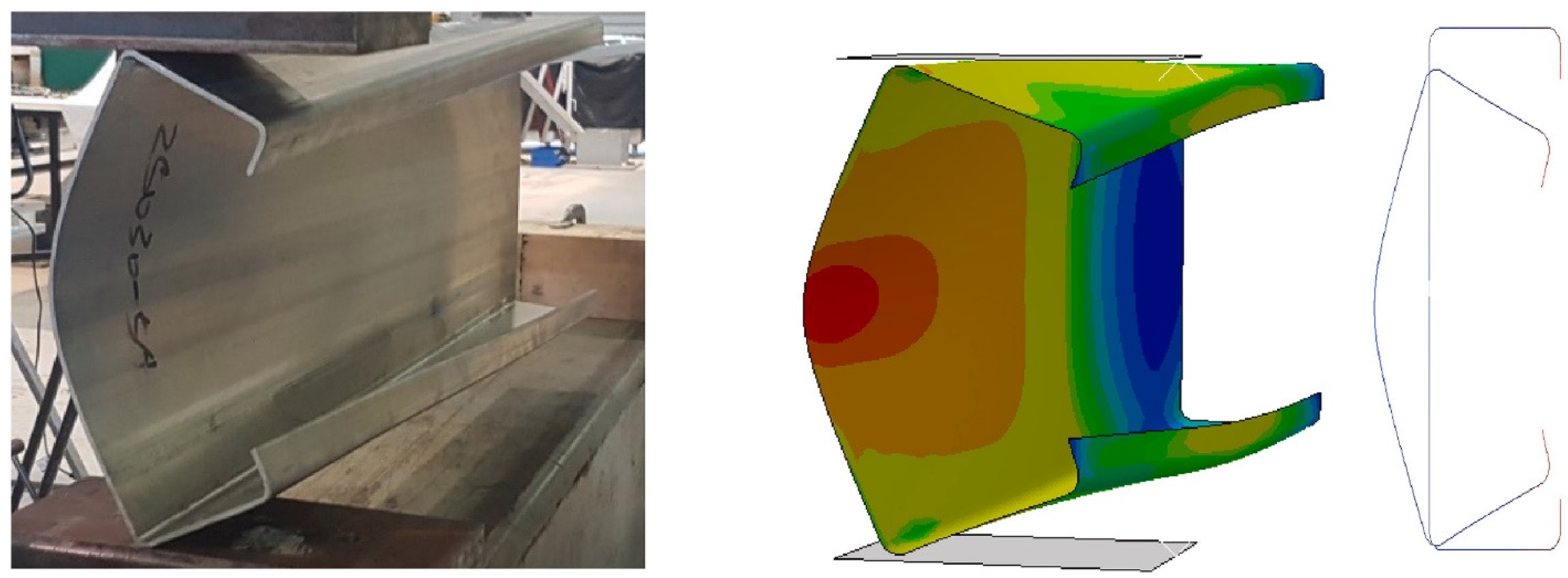
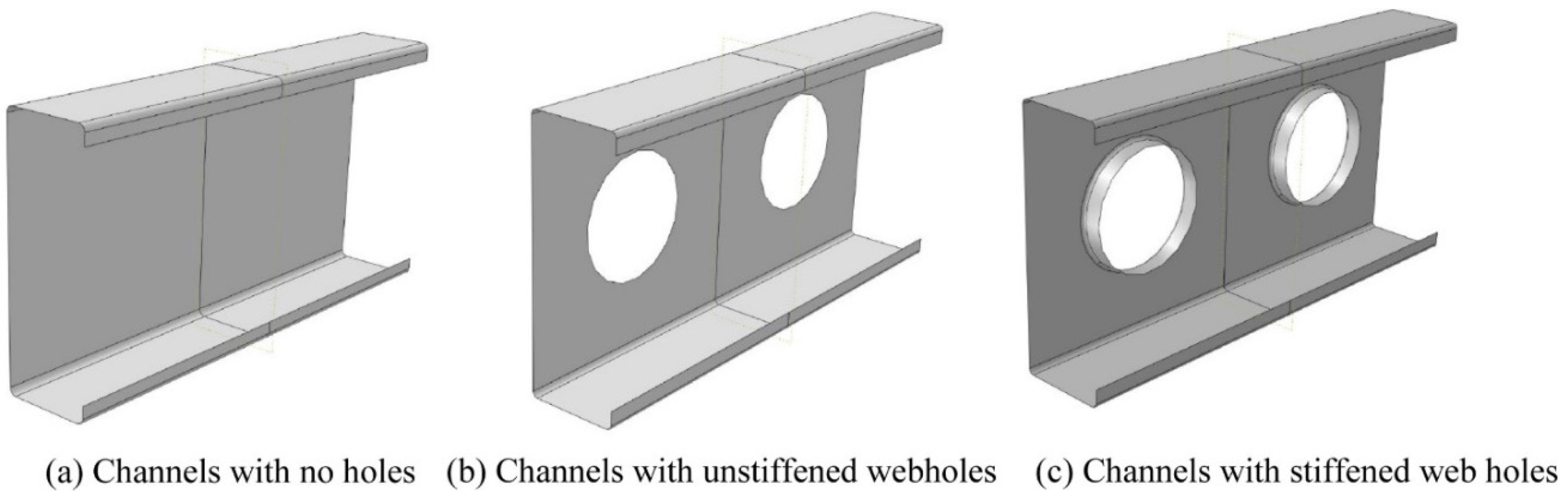
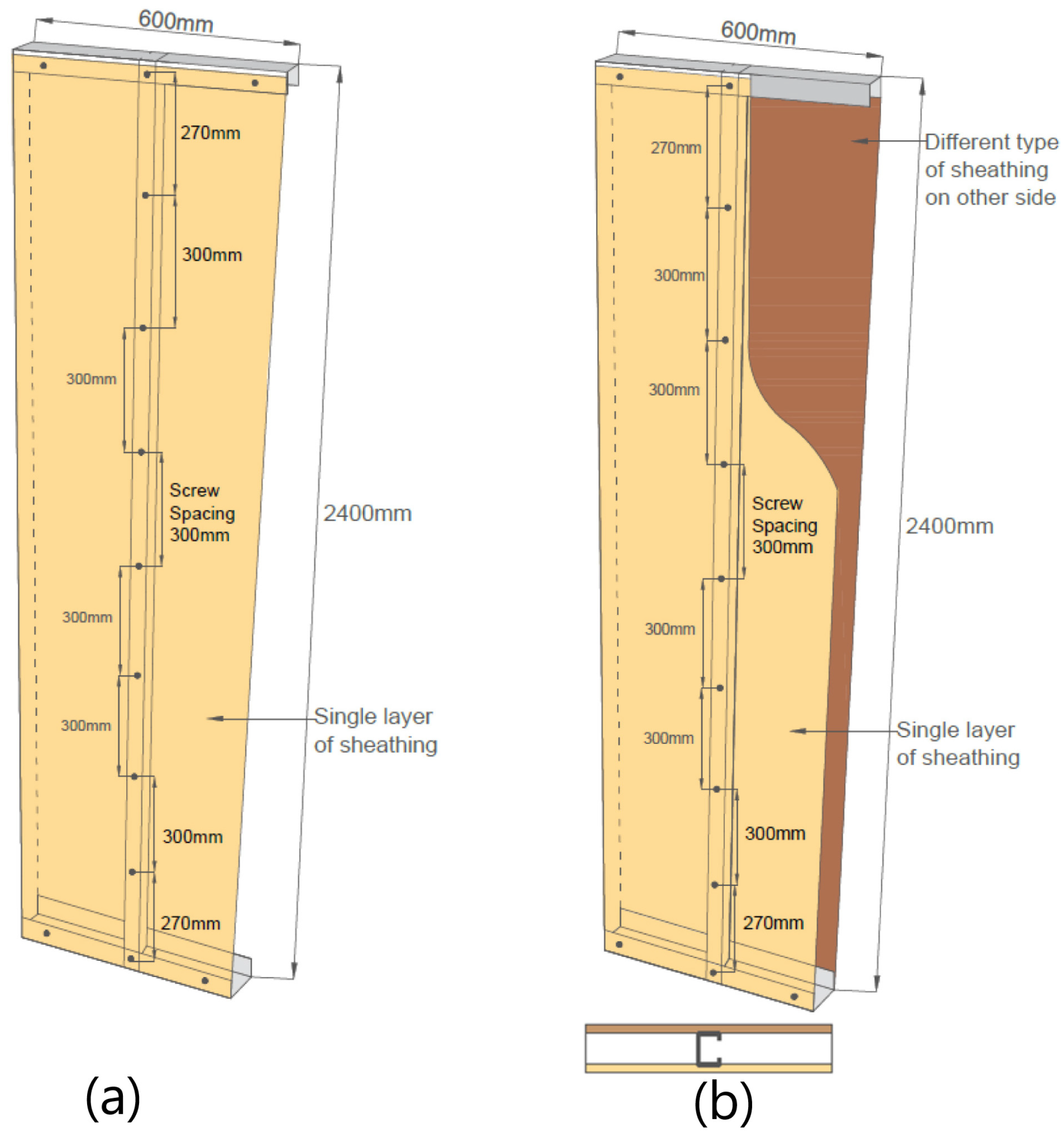
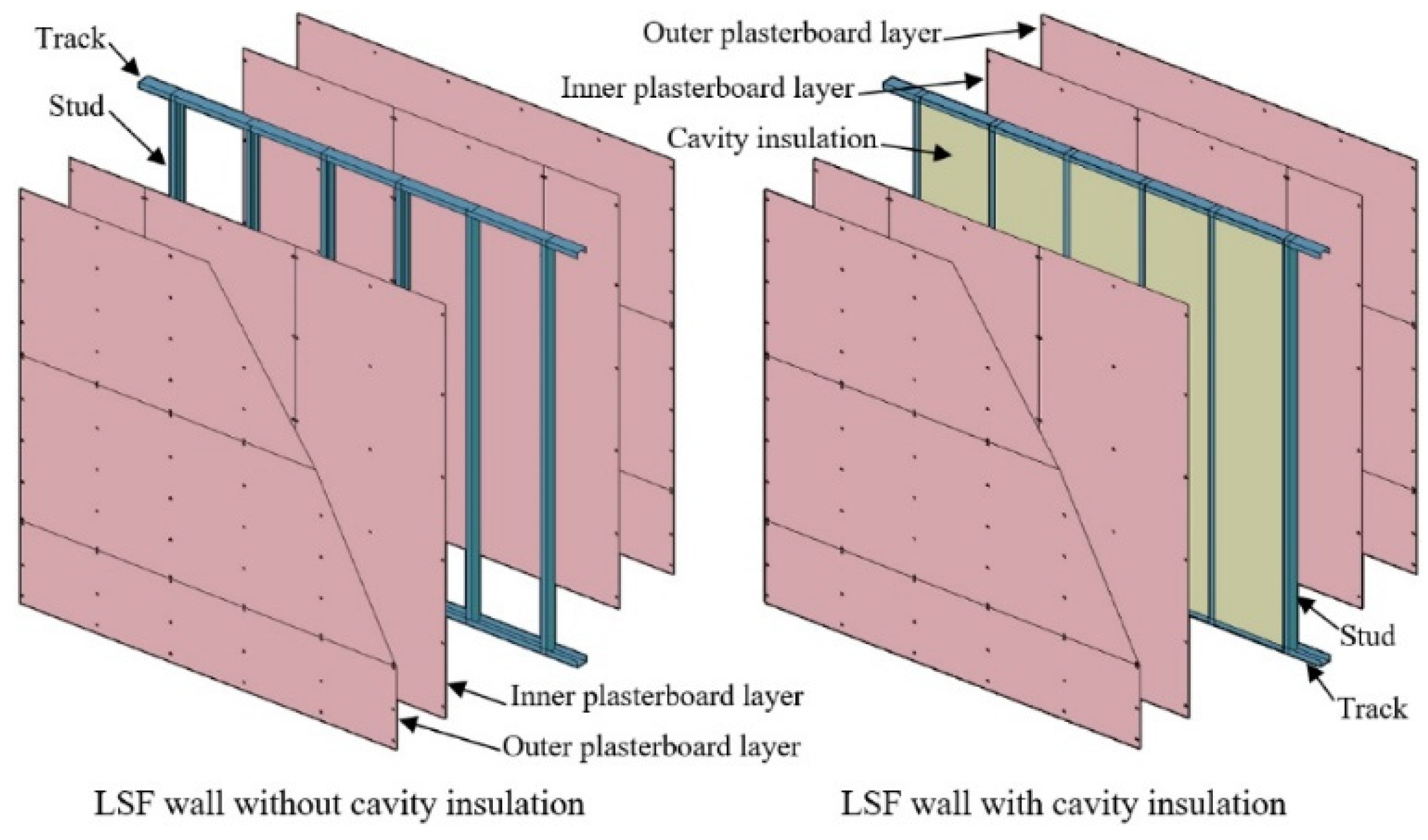
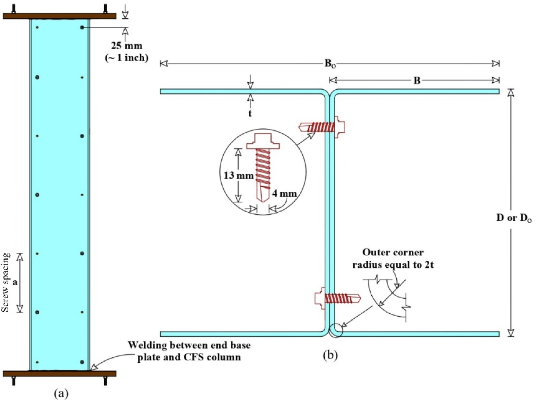
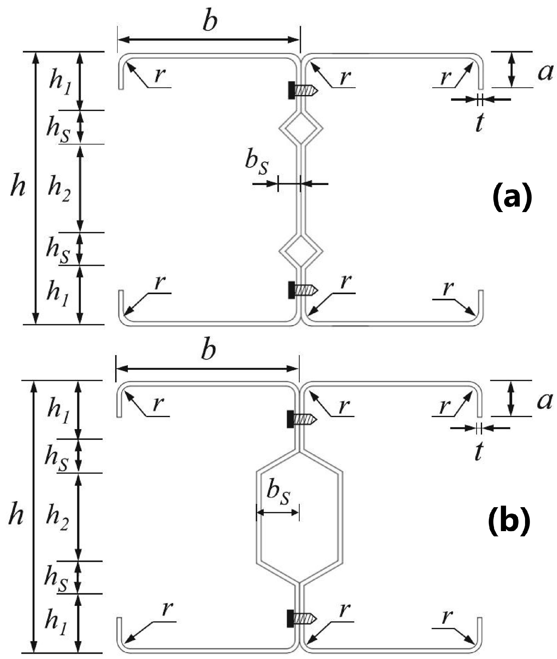
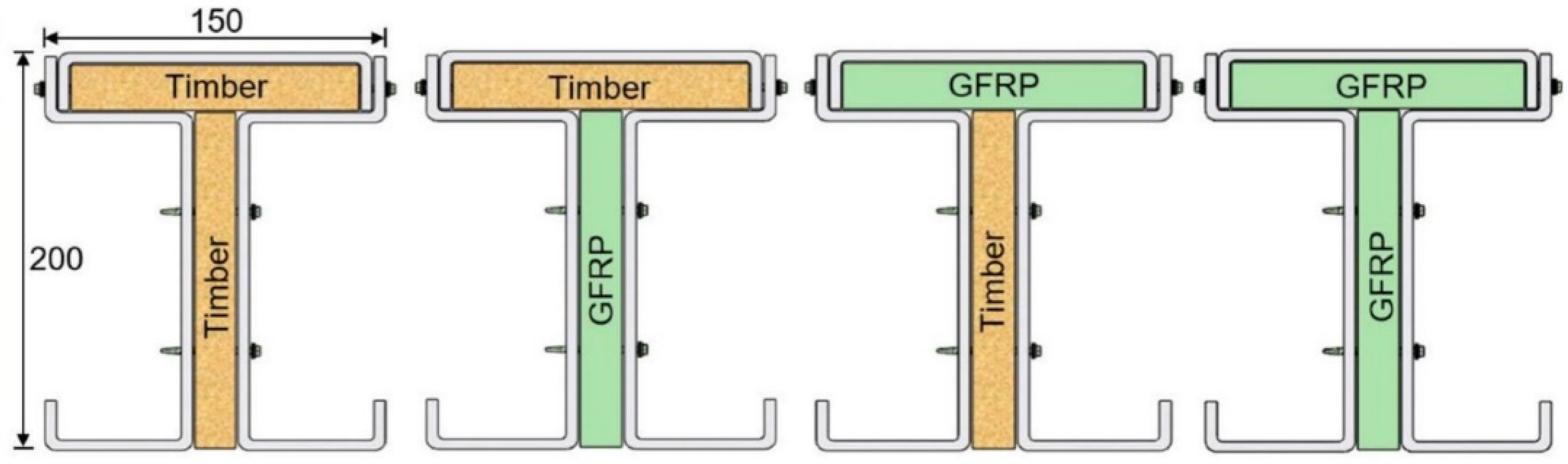
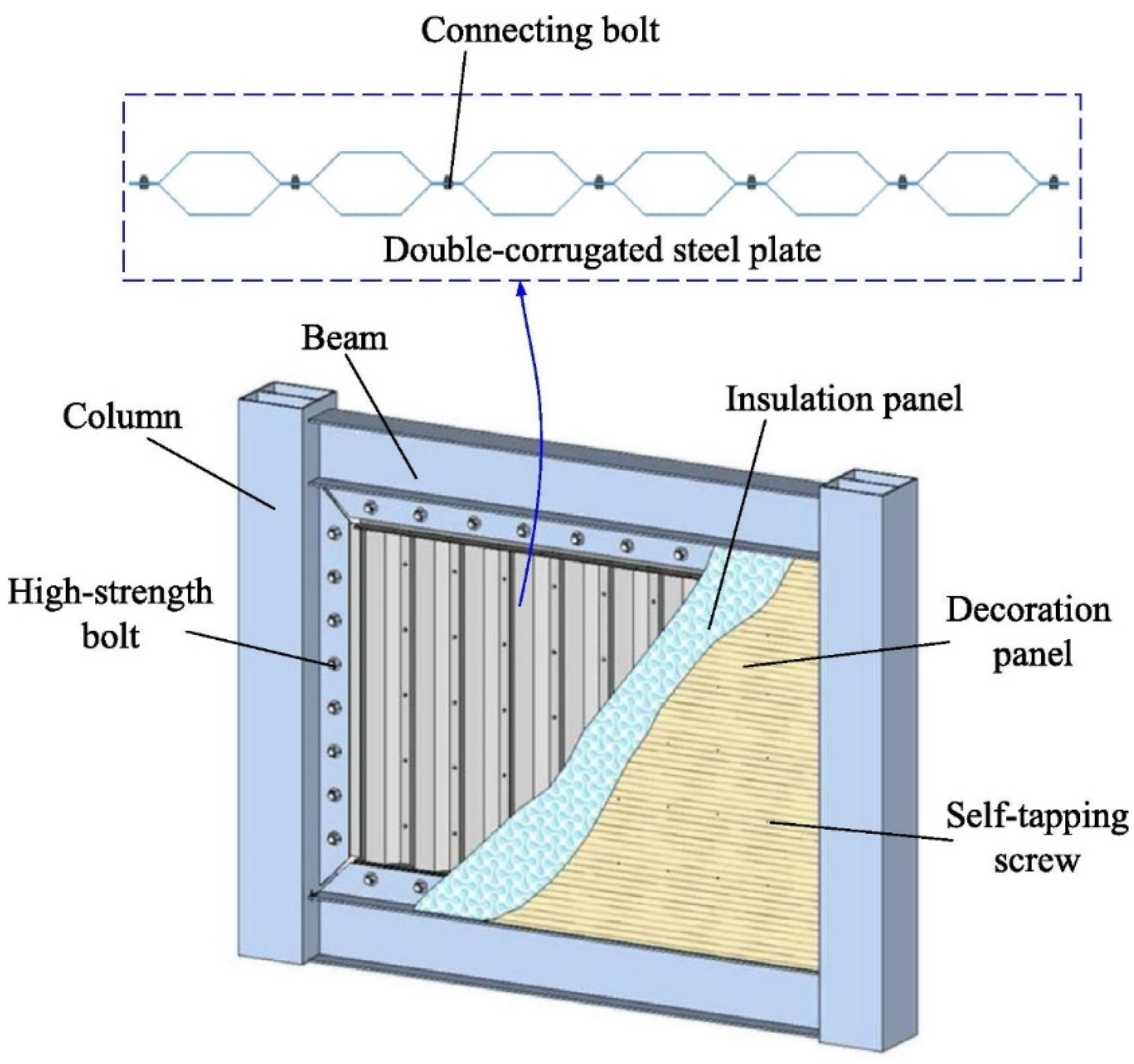
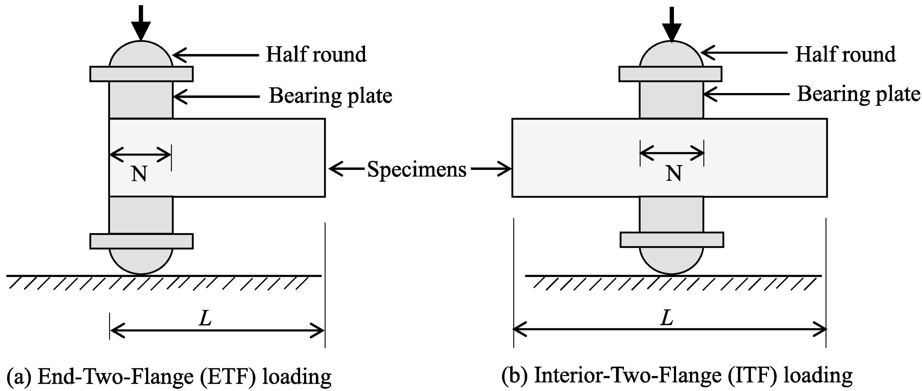
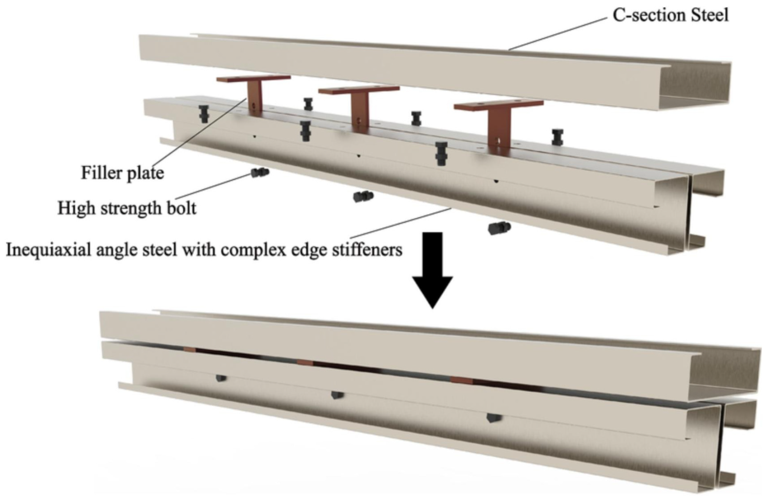
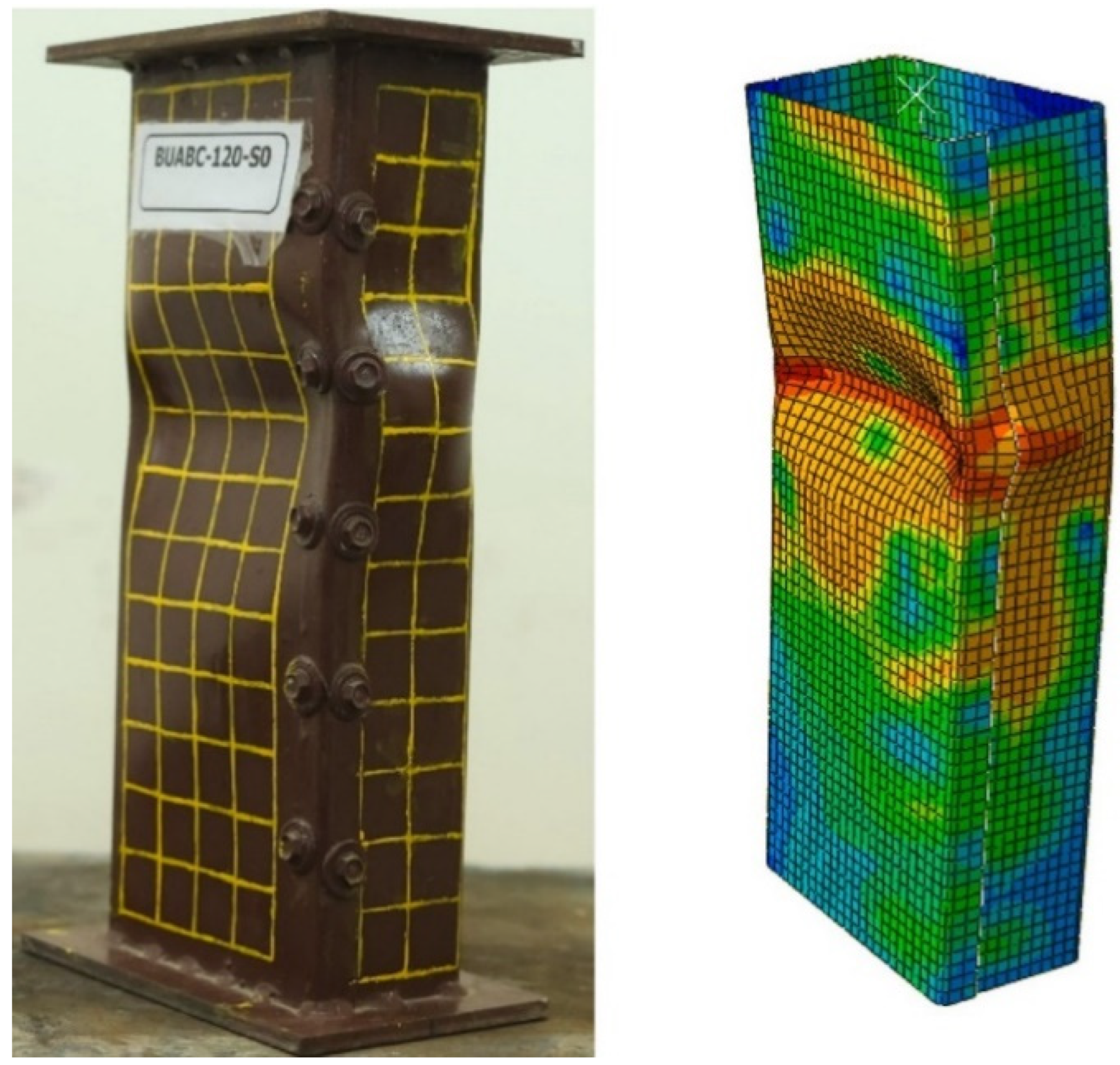
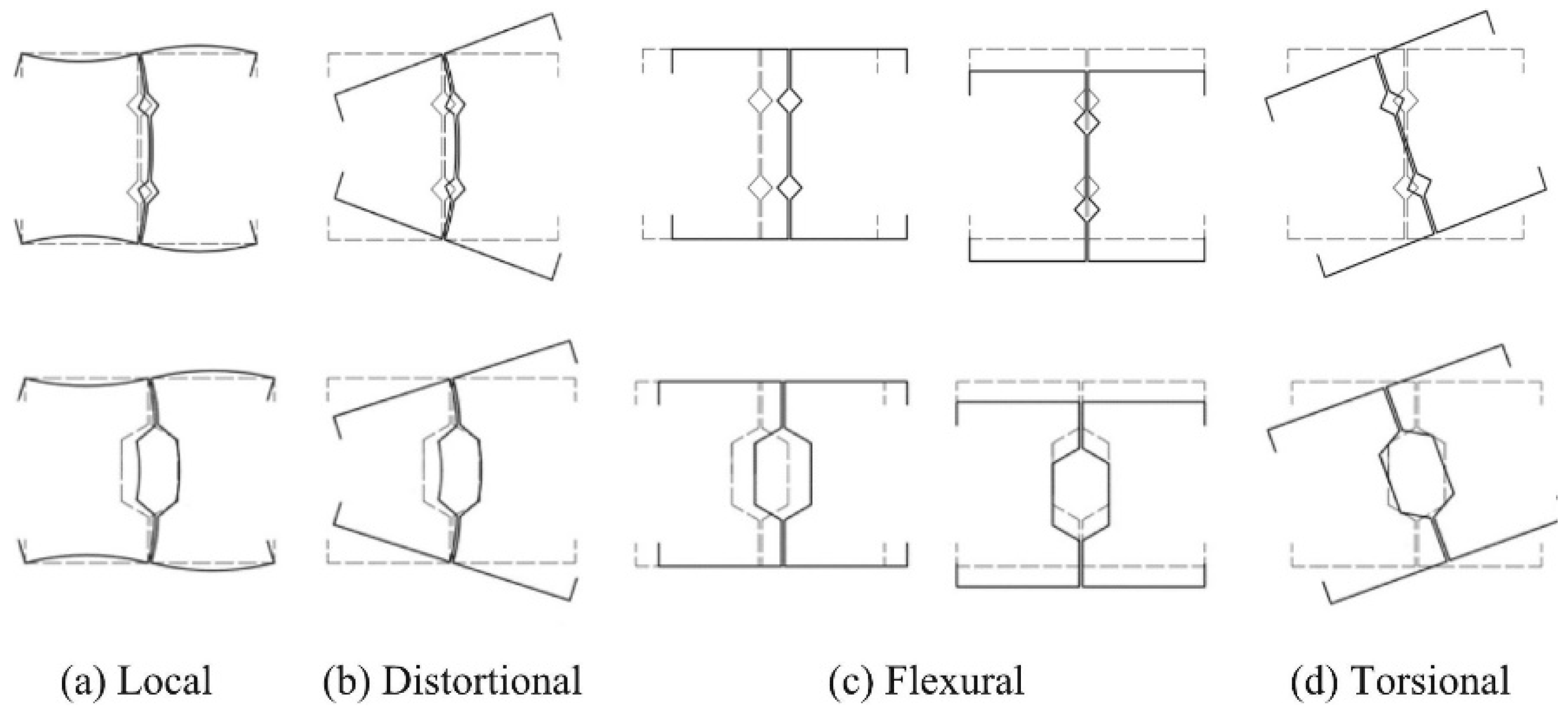
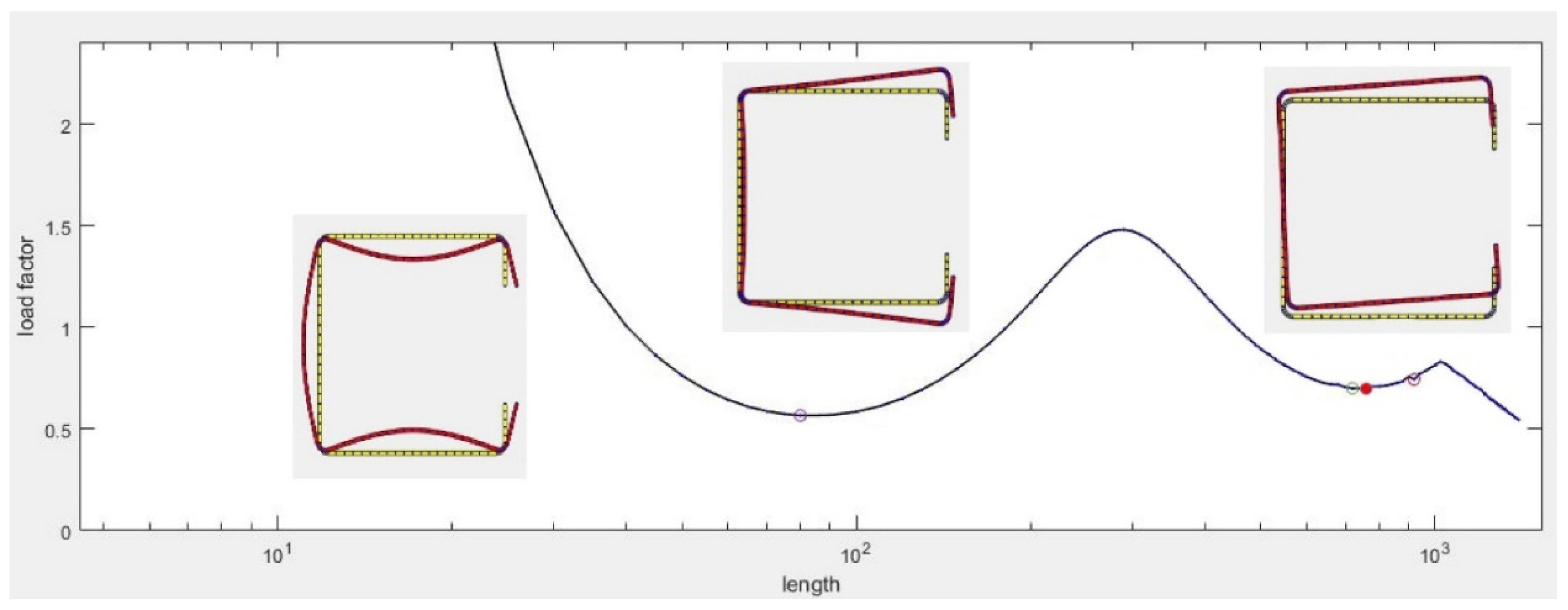
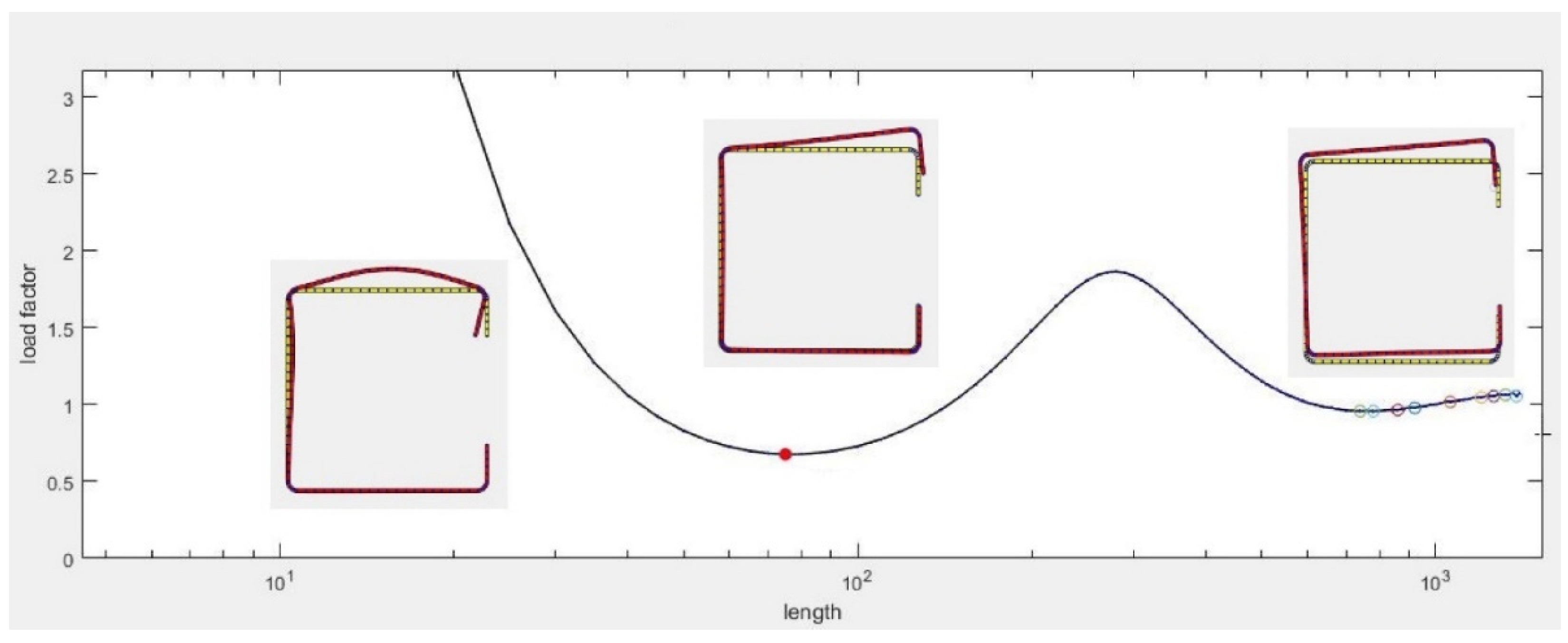