Article

Design Analysis of Mass Timber and Volumetric Modular Strategies as Counterproposals for an Existing Reinforced Concrete Hotel

1
Department of Applied Sciences, University of Quebec at Chicoutimi (UQAC), Saguenay, QC G7H 2B1, Canada
2
School of Design, University of Quebec at Montreal (UQAM), Montreal, QC H2X 3X9, Canada
*
Author to whom correspondence should be addressed.
Buildings 2024, 14(4), 1151; https://doi.org/10.3390/buildings14041151
Submission received: 13 March 2024 / Revised: 8 April 2024 / Accepted: 17 April 2024 / Published: 19 April 2024
(This article belongs to the Special Issue Timber Buildings - Design for the Future)

Abstract

:
Construction professionals work in silos and use traditional design and construction methods. The growing demand for rapidly built and high-quality construction is making off-site manufacturing mainstream. Studies have shown that collaboration among all stakeholders is a necessary component for success in the construction of such buildings. This multidisciplinary study of an existing concrete hotel aims to explore an alternative structural design in mass timber or volumetric modular construction. To this end, the reinforced concrete floor plan of Club Med de Charlevoix in Quebec, Canada, was used as a benchmark for two different structural systems. The first strategy investigated CLT (cross-laminated timber) and glulam columns to replicate the reinforced concrete system (column–slab), while the second involved maximum prefabrication (volumetric modular construction). Both mass timber and volumetric modular strategies can lead to a smaller carbon footprint. The main conclusion is that the plan should be designed from the outset to be either traditional or prefabricated since major changes are required if the choice is made to switch from one system to the other. Moreover, when structural systems maximize off-site construction, such as volumetric modular construction, the various professions need to be included during early planning. This is necessary to avoid task duplication and prevent the neglect of considerations such as manufacturable dimensions and partition organization.

1. Introduction

1.1. Prefabrication Definition

Pressures stemming from lagging productivity and quality in on-site construction have led to a renewed interest in off-site construction [1]. Off-site construction can be defined as building segments that are constructed in a factory and transported for final assembly on-site [2,3]. Svatoš-Ražnjević describes different levels of timber prefabrication [4], categorizing them into 1D frame structures, 2D bearing walls, 3D volumetric modules, and a hybrid or combination of these three categories [4,5]. Overall, building composition can be placed in the following categories: 2D, 3D, hybrid podium, open building system, framed unit system, or hybrid cored–modular [6]. For each of these, the construction process consists of two phases: production in the factory followed by on-site assembly. The level of prefabrication is established according to the percentage of activities carried out in the factory [7]. The main differences between modular and traditional methods are the greater need for collaboration, transportation, supply chain logistics, engineering requirements, and comprehensive design from the outset [8,9,10]. Off-site construction is not specific to any type of material. Timber has been proven to be suitable for every level of prefabrication and can help to increase productivity [11]. In addition, certain tasks can be undertaken off-site, while other work, such as casting foundations, proceeds on-site. This overlapping of tasks leads to time savings [11].

1.2. Prefabrication Advantages

Off-site manufacturing is increasingly promoted for several reasons. The use of mass timber prefabrication can reduces the project timeline, saves costs, and has a lower environmental footprint [12]. Modular construction can reduce on-site labour by approximately 50%, site management costs by 8% to 15%, and project scheduling by 30% to 50% [13]. In the specific case of a basic hotel design, the size of a room is generally compatible with a volumetric module [13]. These percentages usually depend on the type of project. For example, other authors, such as Wozniak-Szpakiewicz and Zhao, have described a schedule reduction of approximately 39% and a cost reduction of between 8 and 16% [14]. Modules have the advantage of being factory-built to reduce material waste and can be transported to the construction site 80–95% completed. However, they sometimes require structural redundancy for transport. Therefore, they are complex structures, and the integration of 3D modelling and project management software is essential to federate design, fabrication, and construction data [15]. Another advantage of modularity is the potential for reuse. Modules can be designed to be disassembled at the end of a building’s lifespan [16]. When compared to traditional constructions, the literature argues that off-site constructions are more sustainable, have better quality control, improve safety, produce less construction waste, and can reduce construction schedules [3,17,18,19,20].

1.3. Prefabrication Difficulties

Most countries lag in the adoption of off-site construction [1,21]. Timber volumetric modular buildings imply a complex and collaborative design process. Further, as their novelty requires more education for engineers, architects, and builders, professionals often opt for standardized steel or concrete construction models that are more prevalent in their studies [22]. In Egypt, the application of off-site manufacturing in the construction sector faces significant challenges: experts and engineers indicate that high initial costs, longer lead times, and market demand uncertainties are the primary factors [17]. Obstacles such as supply chain complexity [3], unclear procurement methods [23], and cost uncertainties [1] also challenge adoption. Payment and contractual distinctions also create impediments to off-site construction. For example, in traditional construction, the builder generally pays for materials when they are delivered on-site. However, with off-site constructions, manufacturers struggle financially because they finance and produce constructions before receiving payment. The planning and production of a module can start approximately 6 months prior to delivery; thus, during this process, manufacturers need to cover the costs of material and labour [23,24]. Another difference between off-site and on-site construction is the responsibility transfer from the builder to the manufacturer of the material supply [25]. Verifying the design of the structure to meet the expectations of the architect and engineer is a challenge, as builders deal with the construction on-site, but suppliers cannot verify that everything has been assembled as requested. For example, the supplier does not know if the volumetric module has been installed perfectly. In addition, the engineer is unable to verify the internal elements of the finished walls of a volumetric modular construction.

1.4. Challenges

While the “2015 Solid Timber Construction Report” summarizes 18 case studies regarding cost and schedule savings [26], few studies focus on the detailed processes and obstacles that impede collaboration between builders and suppliers in terms of the coordination of off-site prefabrication [27]. This is attributed to the fact that collaboration, in general, is lacking [28]. Moreover, there are limited publications available in the literature concerning the analysis of the limitations and possibilities of low-rise multistorey timber prefabricated constructions [4]. Thus, designers struggle to propose an optimized design since knowledge about volumetric modular design criteria is not sufficiently addressed by curriculums [29]. These limitations include a lack of integration, collaboration, and communication between project participants [30]. Few studies deal with procurement management in off-site constructions and with decision-making tools to help practitioners select the appropriate procurement method and system [5].

1.5. How to Increase Prefabrication

To increase uptake, the industry needs to enhance its competitiveness, improve the design process, and shorten the development cycle [31]. Government policy should also include up-to-date industry courses and requirements along with job opportunities to enhance practical training [32]. In a previous study, the procurement method was a significant barrier to the adoption of off-site construction. The critical factors in this method are price uncertainty, technical complexity, and design reliability [33]. In the first steps of conception and throughout the process, it is recommended that an integrated design be implemented between architects, engineers, contractors, builders, and volumetric module manufacturers [16]. Consequently, it is essential to identify the responsible party for each stage of the project to avoid unaccomplished or poorly executed tasks [34]. A procurement model for volumetric off-site manufacturing has been proposed by Charlson and Dimka; they assert the requirement of a single point of responsibility that promotes integration [35].

1.6. Aim of this Article

This article aims to demonstrate the multidisciplinary nature of prefabricated building constructions. The reinforced concrete plan of Club Med de Charlevoix in Quebec, Canada, is studied to evaluate alternative timber construction and volumetric module strategies to closely replicate the existing plan (post–slab). For each building system, architectural, industrial, and civil engineering elements will be analyzed to highlight their interdependencies. Timber was proposed as an alternative because numerous life-cycle analyses have shown that wood products offer undeniable environmental advantages, such as a reduced environmental footprint, over other materials, including concrete and steel. In addition, timber buildings are associated with lower greenhouse gas emissions and less waste [36]. This paper’s scientific contribution is based on the importance placed on multidisciplinary teamwork and on the comparative analysis between conventional and alternate prefabricated multistorey timber construction.

2. Materials and Methods

The study approach for this article is divided into 5 phases, as shown in Figure 1.

2.1. Phase 0: State-of-the-Art Review and Building Features

Phase 0 reviewed the state of the art in prefabrication and the challenges encountered in other similar buildings. The case study hotel was Building B of Club Med de Charlevoix in Quebec, Canada. The characteristics and plan of that as-built building were also studied. Building B houses all guest rooms, as opposed to building A, which contains the atrium, the pool, and all services and is not included in this study.
The building is found in a bucolic mountainous site; six storeys face the mountain, and eight storeys face the St. Lawrence River. It has a height of 19 m facing the mountain and 25 m facing the water, a total area of 6582.28 m2, and a footprint of 994.52 m2. The building layout includes five room types; these are presented in Table 1.
Type G0 rooms are those with an integrated mini kitchen and are allocated to hotel employees. C3 and A3 rooms are almost identical; however, C3 rooms are shorter to allow a wider corridor on the floors used as emergency exits. A4 rooms are the most luxurious room category, as they are the largest. C4 rooms are similar to A4 rooms but have smaller dimensions.
During Phase 0, a discussion was held with the engineering firm that developed the initial design for the concrete hotel. This meeting aimed to ensure that the proposed counterproposal study would meet the initial constraints and determine which parameters could be optimized for timber. These are listed below. Moreover, the objective was to understand which type of structural systems comparison would address the construction industry’s enduring challenges. When an engineering firm receives a request to suggest an alternative to a reinforced concrete plan for a building, the objective is to maximize its options without transforming the initial building design. As a result of this meeting, five essential parameters and three optional ones were put forward to guide the project.
The essential parameters are as follows:
  • Keeping the first two floors facing the water only since the other side faces the rockface;
  • Designing alternatives according to the same building code (2010);
  • Avoiding foundation design for the new timber building;
  • Conserving similar building organization, dimensions, and the number of storeys.
The optional parameters are as follows:
  • Conserving an equal or slightly higher number of G0 rooms;
  • Conserving a similar column layout;
  • Conserving a similar number of rooms of each type.

2.2. Phase 1: Architecture

Phase 1 focused on the hotel’s architecture. Whether using a post-and-slab construction system or a volumetric modular system, the aim was to analyze the consequences of a transformation from concrete to timber. To understand the particularities, a state-of-the-art review and meetings with architects were held. The first step dealt with analyzing the concrete architectural plan to understand the structural grid in relation to different room typologies.
For the column–slab system, assumptions were used to reproduce the glulam columns in dimensions as similar as possible to what they were in concrete as a first hypothesis since it is the quickest thing an engineer can do to see if it is realizable or not (see Table 2). These assumptions aim to ensure that a consulting engineering firm is not required to go through the entire dimensioning process again, but the dimensions are not optimized.
A series of iterations were carried out to determine the possible new layout. Since volumetric modules of identical room widths had to be arranged to be aligned vertically, rooms needed to be rearranged. To this end, six different scenarios were devised and analyzed according to the seven parameters (see Table 3). The order of iterations was not significant. All of the iterations were concepts recommended in Phase 0. The weight of each criterion was established following discussions with architects. Following an agreement between four architects, the values obtained were subjective. During each iteration, an Excel spreadsheet was first used to visualize the proposed distribution by floor, as well as the dimensions of the corridors and the total dimensions of the building. Then, when the proposal seemed appropriate, the superimposed volumetric wall modules were drawn to ensure feasibility.

2.3. Phase 2: Industrial Engineering

Phase 2 focused on industrial engineering in order to understand the industry challenges and possible optimizations. The aim was to find out how to apply the architectural peculiarities identified in Section 2.2 and to determine what modifications should be carried out. During this phase, it was essential to determine the appropriate type of prefabrication since each possesses a unique potential. According to the building code requirements in Canada [37], light-frame construction cannot be used for buildings over six storeys. Therefore, CLT modules were used. However, the industry in Quebec is geared toward panelization more than toward modular volumetric construction. To gain a greater understanding of the reality of the industry and to be able to apply the necessary concepts to the project, meetings with manufacturers of light-frame timber and CLT volumetric modules were held.
A transportability study was also carried out to ensure that the desired modules would not only be simple to produce but also transportable without incurring additional costs. In doing so, the architecturally defined room dimensions needed to be revised to accommodate transport units without additional costs. For a small number of rooms with non-standard dimensions, the supplier may prefer paying for special transport rather than building numerous small modules. When modifying dimensions, the function of the rooms must be taken into consideration. In the case of a room used as a living unit for employees, dimensions cannot be reduced since the room is not only used as a place to rest but also as a living space (usually with additional amenities such as a small kitchen).

2.4. Phase 3: Civil Engineering

Phase 3 focused on the civil engineering aspects, ensuring that the architectural and industrial concepts were feasible and whether any structural modifications were required.
Two different eight-storey buildings were designed and modelled using the finite element method (FEM). RFEM 6.03 software was used for both simulations [38], and it used the CSA O86-19 parameters and requirements [39]. The first building was modelled using CLT for horizontal elements and glulam for vertical elements; the other building was modelled using volumetric modular construction. In the first model, the aim was to reproduce as closely as possible the same outlines of the concrete structure to compare them. The objective of the second model was to study volumetric modular construction. For modelling columns, 1D linear elements were used, whereas 2D plate elements were utilized for modelling slabs and cores. The materials in the columns were assumed to follow an equivalent isotropic linear elastic stress–strain law, given their exposure solely to axial loading. In contrast, the CLT wood was modelled with orthotropic linear elastic behaviour. The vertical gravity-load-resisting system was not the same for both concepts. For the column–slab concept, glulam columns were used as the vertical gravity-load-resisting system; for the modular concept, the wall of the volumetric modules was used.
For the column–slab concept, the beams were assumed to be 20f-EX-grade Douglas fir-larch, and the slab was assumed to be Nordic structure CLT [40]. All connections were considered, with only the moment in the plan of the section (y and z) fixed for the columns. The moment in the height of the column (x) was released. For the volumetric modular concept, wall, floor, and ceiling panels were first modelled, assuming that Nordic X-Lam 89-3s were used. In both construction systems, slabs, staircases, and elevators were modelled on Nordic Structures CLT. All loads were determined according to the National Building Code of Canada (2015) (NBCC) [37] and are shown in Table 4. Building B of the hotel under study falls into Group C, as it is primarily used for residential purposes.
All elements were designed to comply with the ultimate limit state (ULS) and serviceability limit state (SLS) requirements. Load effects were obtained directly from RFEM structural analysis and wood verification for all load cases required by the NBCC. However, it should be noted that the design of the connections was not within the scope of this paper. For all cases, surface loads were applied directly to floors and roofs. Table 5 illustrates the load combinations that were used in this study. In this table, D, L, and S represent dead, live, and snow loads, respectively. ULS is the ultimate limit state, and SLS is the serviceability limit state.

2.5. Phase 4: Analysis

Finally, Phase 4 focused on understanding and assembling the various results obtained and making general recommendations. The results were analyzed to make recommendations and highlight the advantages, consequences, and characteristics of transforming a concrete hotel building plan into timber using a column–slab and a modular construction system. To carry out this analysis, information from phases one to three was combined to design an alternative building and validate its feasibility. Once these alternative timber buildings with column–slab and modular construction respect all parameters, Gestimat was used for a preliminary greenhouse gas emissions comparative analysis of the existing and alternative building designs [41]. The Gestimat analysis concerns only GHG emissions from structural materials in the first phase of the building life cycle (production phase: extraction of raw materials, transport, and manufacturing). It has been used for similar subjects in other studies from Lecours and from Cardinal [42,43].

3. Results and Discussion

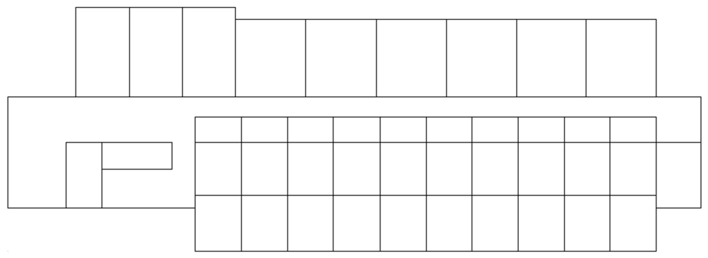
3.1. Reconceptualization of Developments and Planning: Architectural Analysis

Phase 1 of the methodology focused on the architectural aspect of rearranging the partition walls from the concrete hotel plan to wood. To this end, both structural systems were analyzed (mass timber and volumetric modular systems).
In traditional construction, the columns cross the building from bottom to top at the same point, and gravitational loads transfer through them. In a hotel, walls and columns are generally on the same axes, and rooms are designed according to structural grids to avoid having columns in open spaces. Concrete slabs and timber panels do not have the same maximum span. Keeping the same column grid is not always possible. As an example, an added column that would potentially end up in the middle of a room is not architecturally acceptable. If this occurs, a counterproposal must be reorganized according to new grid lines or modlines.
As expected, redesigning the plan from concrete to timber implies a completely new structural grid, as timber is optimized with smaller spans. More or larger columns are required to achieve the same performance. From an architectural point of view, if columns are added, they should be at room intersections or at room–corridor intersections to avoid columns in rooms. From another point of view, if columns are enlarged, they should be increased only in the room space since the corridors are already designed with the minimum dimensions allowed. Following a discussion with the industrial partner, the decision was made to increase the column sizes rather than add more. CLT slabs need to be designed with the correct panel dimensions. The existing building’s non-rectangular geometry made it unsuitable for this type of slab. The numerous notches in the building, at inappropriate distances, meant that CLT panels would not be optimal, increasing material costs. To be optimal and economical from an industrial point of view, the building plan should follow a 2.7 m wide panel modular grid since this is what Canadian manufacturers can produce.
In simulating modular volumetrics, Figure 2 shows the superimposition of the building’s various partitions of the concrete plan. In a hotel context, the volumetric module system is generally considered as one module per room. The rooms need to be arranged so that they stack perfectly, with identical widths.
In the original Club Med of Charlevoix design, the partitions were not systematically aligned from one floor to the next, creating challenges for connections and module stacking. If a CLT module design is used, loads in walls must follow a vertical path.
Corridor dimensions are important, as they are calculated based on the minimum dimension per person for fire evacuation. In the case of a horizontal walkway connected to another building, corridors can be used as an evacuation passage if a fire breaks out in other buildings, and, therefore, they must be wider. Hence, corridors cannot be reduced in width. Nonetheless, rooms need to be optimized compared to uninhabitable space since corridors represent unprofitable space. Corridors facing various exits, staircases, and elevators must be widened to allow people to wait in front of them without impeding circulation.
Rooms that qualify as more luxurious are generally on the upper floors in order to take advantage of the best possible views. For example, Club Med’s higher-end rooms must be on the upper floors and face the river. On the other hand, it is possible to create a room layout with a higher number of narrow rooms with a nice view in order to be more profitable and charge more for a larger number of rooms. Furthermore, for luxury rooms, it is possible to place them on the garden level if a courtyard or terrace is offered. As far as the number of rooms, alternative construction should aim to respect the original quantities. The hotel’s profitability calculations are based on this number, but changing a structural system will always lead to a certain variation.
For the first simulation, the layout was designed to respect the building’s exterior envelope as much as possible. However, the appropriate way to accomplish this is to define a central corridor and place the rooms on either side of it. A corridor is generally as straight as possible. Considering all the above concepts, various iterations were carried out to obtain the final proposed solution. An alternate modular geometry to the concrete layout was proposed for Club Med Charlevoix, as shown in Figure 3.
Figure 3 illustrates the superposition of partitions on hotel floors according to the proposed configuration. Table 6 summarizes the area associated with every storey. There is, therefore, an adequate load descent in the hotel walls, which are superimposed on the same axes, regardless of the floor.
The new proposal shown in Table 7 includes four additional rooms for permanent employees. These additional rooms can be used for internships or booked like the other types.
The quantity and position of the prestigious rooms remain the same in the alternate solution (facing the water and on higher floors). During the rearrangement, the narrowest rooms are placed facing the river so that they can be booked at a higher price, leading to greater profits. The design will vary from conventional construction to volumetric modular construction. Indeed, if the plans are drawn up for traditional constructions, moving to an alternate in volumetric modular construction will require rooms and dimensions to be modified and the height of the building will be increased to account for structural redundancy. There is no universal plan for all construction systems: dimensions, grids, and arrangements will vary according to structural systems.

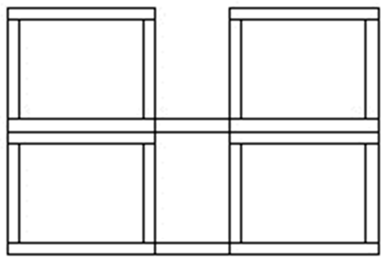
3.2. Understanding How the Choice of an Industrialized Construction System Impacts Both the Architectural and Structural Systems: Industrial Engineering Analysis

Phase 2 of the methodology focused on the industrial engineering aspect of the plan change from concrete to wood. To this end, both structural systems were analyzed.
It is important to note that before deciding on a volumetric modular strategy, it is necessary to ensure that the building site will have sufficient space to store the modules. If this is taken into account, a crane will be mobilized less often for setting the modules. There are various methods for raising the modules, including inclined cables positioned at the corner or edge, with or without a spreader beam. To reduce internal forces, prevent diagonal pulling in the module, and attain optimal static weight distribution, it is common practice to employ a lifting frame or a main beam with crossbeams [44].
Within the column–slab alternate design, column dimensions cannot be established in the same way as concrete dimensions. Manufacturer catalogues include specific dimensions for the materials produced. From an optimization point of view, to avoid waste and unused materials, the geometry of the building plan must respect the manufacturer’s optimal dimensions of CLT. Any timber design must consider modular and manufactured available dimensions to avoid waste.
For the modular simulation, modules had a length equal to the total width of the building. These structures included two bedrooms and corridor space, as illustrated in Figure 4.
Modular manufacturers suggested that the width of the existing hotel was too large for this type of module. Further, this type of layout can lead to poor sound insulation between the corridor and rooms. This is a critical issue to be avoided in hotel construction. A different layout for corridor management and sound transmission is illustrated in Figure 5. In this layout, each room is independent and has its own module. The corridor has a CLT slab floor. This saves headroom for the electromechanical equipment since only one CLT slab is used for the floor, and there is no duplication with the ceiling. By having independent room modules, sound transmission is reduced in comparison with the previous layout.
Indoor acoustic comfort is an important design consideration with volumetric modular and lightweight construction systems. To achieve good indoor acoustic comfort and insulation in the hotel, the choice of modules is essential. Additionally, the location of the various ducts must be determined from the outset. Based on a modular case study by Getzner, 90% of sound transmission occurs through the module walls. To effectively minimize the transmission of sound and vibrations through these walls, Sylomer elastic bearing strips can be employed. These strips ensure load transfer between modules and prevent the creation of sound and vibration bridges [45].
In the analysis of transport regulations, an escort is required when the width of an element exceeds 3.75 m [46]. To minimize costs, dimensions should be optimized according to transport. Dimensioning according to manufacturability and transportability (dimensions and materials) is the basis of volumetric modular design. Since the construction industry supplies materials in pair inches, the proposed dimensions must be multiples of an even inch to avoid unnecessary cutting and waste. Alternate design dimensions must be as close as possible to the original dimensions while still being less than 3.75 m and an even multiple of an inch. In addition, six inches must be subtracted from the authorized transport dimensions to account for the protection that will be added to the modules for transport. To avoid the need for a transport escort, widths for G0 rooms were adapted while retaining the same surface area. However, by doing so, it was no longer possible to create two units per module. Therefore, this option was ruled out. To meet transport standards, the room’s dimensions were slightly reduced or halved, as shown in Table 8.
Moreover, the weight of the modules was an important factor. If modules are too heavy, they will require larger cranes and non-standard transport, which increases costs. Some module suppliers agree that increased variability can be achieved if the exterior finishing is carried out on-site. This step reduces the risk of damage during transport. In addition, when several modules are superimposed, weatherproofing and finishing are easier once the modules have already been assembled. Discussions with module suppliers reveal a key challenge in ensuring the quality of modular constructions: the need for better monitoring of quality consistency from the factory to the construction site. A module could leave the factory with controlled quality but be incorrectly stored on-site.

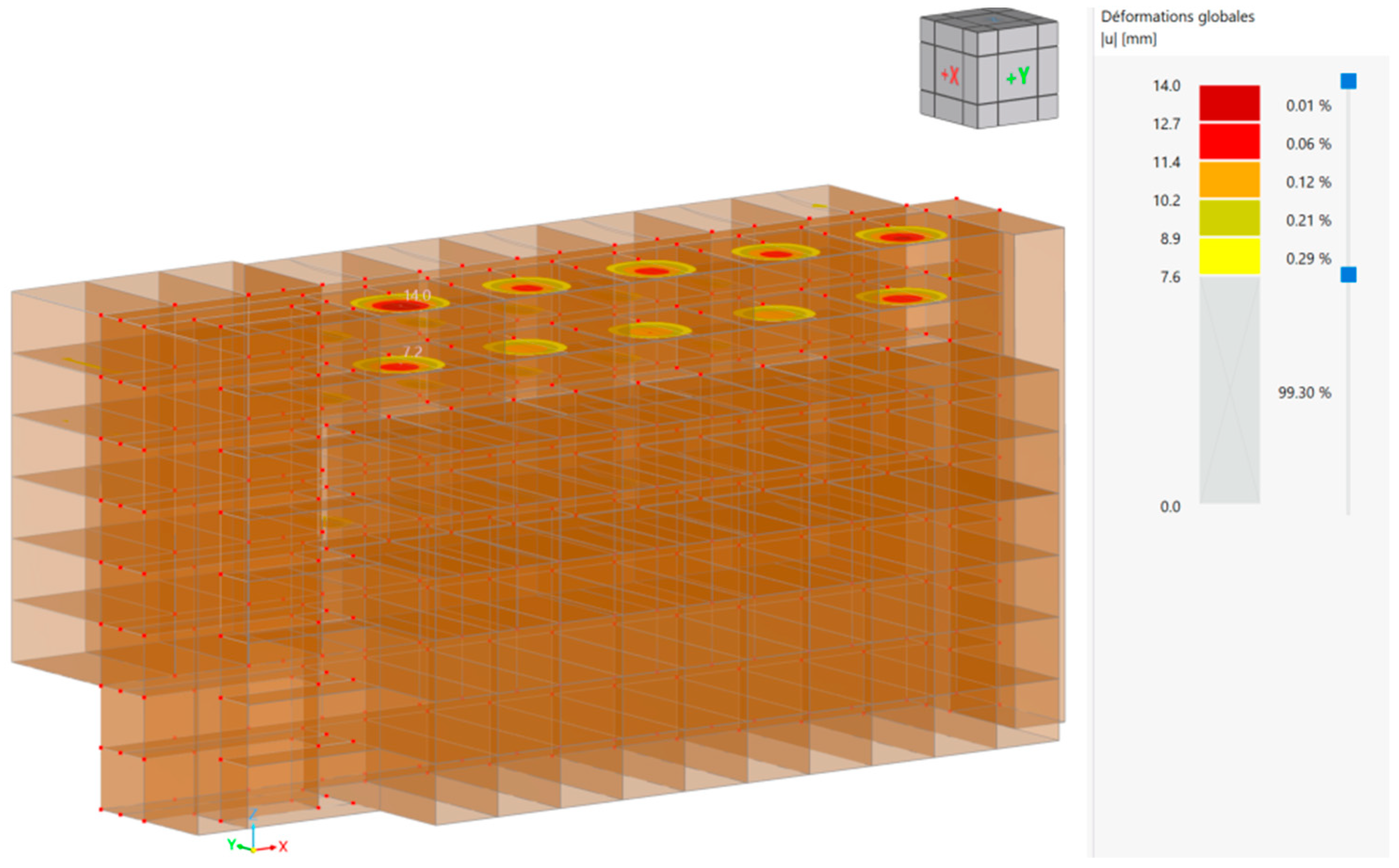
3.3. Modelling of the New Wooden Structure: Civil Engineering Analysis

Phase 3 of the methodology focused on the civil engineering aspect of the alternate timber designs. Thus, both structural systems were analyzed with gravitational forces.
According to the 2015 Quebec Building Code, combustible constructions (made of wood) can have a maximum height of 18 m between the average ground level and the floor of the highest storey [37]. Since the building in question had six floors on one side and eight on the other, verifications were needed: one side complies with the building code while the other side does not. The building’s surface area was permissible according to the number of storeys. The Quebec building code allows 9000 m2 for Group C buildings. The timber column–slab model was simulated to maintain the original concrete plan, as shown in Figure 6.
As expected, deflections were too high when using timber columns with the same dimensions and the same grid as the concrete columns. Increased CLT panel thickness or the addition of more columns was necessary. When analyzing the structural grid and the location of walls, some columns were added, and the thickness of panels was increased to reduce the deflections. As a result, only one major static problem is shown in Figure 7: a deflection of 39.44 mm under the D + L + 0.45 S load combination at the critical point. This span was too large. The staff rooms (G0) are located on the two lower storeys, and their walls are not placed on the structural grid because they are narrower. Because of that, fewer columns are by the walls, and the span is larger. Instead of having columns at every room wall, there are columns every two or three room walls.
The volumetric modular simulation considered volumes added to an on-site-built podium or a concrete foundation. It is important to consider the different tolerances of different materials, as well as the possible tolerance of misalignment during module installation [47]. Figure 8 depicts the modelling of each wall to reproduce the behaviour of the timber structure.
The largest deformation is 14 mm, as shown in Figure 9, using the load combination of D + 0.35L + 0.9S. The maximum deformation is at the top of the building because it is the area with the biggest span. The A4 rooms have double the width of the rooms under them. There is no middle wall in them.
With the volumetric modular design, there are two proposals for the height of the building and the height of the rooms. It is important to note that with volumetric modular construction, each module has its own floor and ceiling. Therefore, when they are aligned vertically, the total height is increased when compared to traditional constructions. If the region has a maximum permitted height in the code requirements, as in Quebec, it is possible to reduce the interior height of the modules. For the same number of floors, a modular building will always be taller compared to traditional buildings that only have one concrete slab that acts both as floor and ceiling. During the design phase, factory and transport standards are considered to limit simulation iterations. In these situations, BIM (building information modelling) can be very useful in coordinating all stakeholders and analyzing issues in advance. One difficulty encountered when modelling a building with volumetric modules is assigning connections. According to the literature, modular connections are generally made in the corners of the modules. However, one of the limitations of the software used (RFEM 6) is that such connections were not possible.

3.4. Integration of the Three Disciplines (Architecture, Industrial Engineering, and Civil Engineering)

There are always interdependencies between disciplines. For the column–slab system, the concrete column grid does not apply to the timber building since additional columns will be needed to reduce deflections. Therefore, these must be considered in the architect’s organization so that no columns end up in a room before the finite element model is produced by the engineer.
For the modular system, the volumetric module dimensions depend on the function of the room, as well as on what is permitted in terms of transport and factory capacity. The type of volumetric module that will be used will depend on what the industry can build in terms of required quantities and the prescribed timeframe (light frame vs. CLT), but also depending on the building’s function. Once the type of module has been chosen, the architect must ensure that the modules respect the dimensions acceptable to the carrier and that, in the plan, the rooms are arranged so that they stack perfectly, with identical widths. The architectural plan must also consider the location of luxury rooms and the dimensions of corridors. Then, once the choices have been made, the civil engineer can complete the finite element model to ensure that the building has the correct dimensions and materials.
As a rule, traditional buildings are built according to separate contracts. There is a designated professional who communicates with the client. Other professionals are responsible for conception and ensuring that everything is carried out according to the plans and specifications. This diagram is illustrated in Figure 10, where the green solid lines represent contracts, and the red dotted lines represent checks.
Following the results obtained in the case study, planning must include all stakeholders from the outset. This integrated project delivery model and its applicability in off-site construction is simulated in Figure 11.
After the integration of the different disciplines, a comparative greenhouse gas emission analysis of the three structural simulations was carried out using the Gestimat tool developed by Cecobois [41]. In the preliminary design of the two wooden structural simulations, certain assumptions were made in the GHG emissions analysis. Firstly, we used the typical modifiable six-storey office building to have representative quantities of reinforcement and connections. Secondly, the foundations and roof were not considered in the analysis because they were not part of the actual structural system comparison. Finally, as the building is non-traditional, with two half-storeys, four full storeys, and two reduced storeys, the total quantities were summed in Excel and entered as the equivalent of one storey instead of six in the software as shown in Table 9.
The reference scenario was based on the structural and architectural plans for Club Med Charlevoix as built in concrete. When modifying the typical building scenario for the volumes of the various elements, the proportional quantities of reinforcement were retained. The room walls were steel light-frame, with 92 mm studs spaced at 610 mm. Exterior walls were also considered as 92 mm steel light-frame studs but spaced at 406 mm. A fiberglass-reinforced gypsum sheathing was added to close the wall and be more comparable to the modular scenario. The load-bearing walls are made of reinforced concrete.
The column–slab scenario was carried out with glulam columns and CLT slabs. The default connection proportions of the standard scenario were retained for glulam: 27.5 kg steel plates/m3 of glulam and 2.825 kg screws/m3 of glulam. For CLT, no values are listed in the database. Therefore, a value of 1.39 kg nails/m3 of wood was recommended by Cecobois. This is the traditional value for wood decking. Exterior walls were considered to be identical to the concrete scenario. Room walls are the same as in the concrete scenario. However, the load-bearing walls are considered with CLT, with the same connection proportions as the slab.
The volumetric modular scenario required more adjustments to the typical building since CLT values are not included by default in the Gestimat 2.0 software. A quantity of 1.39 kg of steel nails per cubic meter of CLT was considered, following Cecobois’ suggestion. The building’s interior and exterior walls are those of the volumetric modules.
We were then able to compare the total GHG emissions of the three scenarios for every material. The results are shown in Table 10. The resulting data illustrates timber’s lower environmental footprint.

4. Conclusions

In conclusion, this study contributes to the field by highlighting timber structures as viable substitutes for reinforced concrete structures. However, as compared to on-site concrete, which offers flexibility, prefabricated timber systems require higher levels of design integration among all stakeholders. The goal is to facilitate the selection of suitable solutions from the initial stages of design, ultimately leading to the development of more efficient and cost-effective multistorey timber construction methods for practical use. Through a comprehensive exploration of multistorey timber design, the insights presented in this paper highlight all the issues and peculiarities when proposing an alternate timber design to a reinforced concrete baseline.
The redesign of a concrete hotel building into timber was studied for a post–slab and modular transformation. The alternate timber design requires additional columns and increasing the thickness of the CLT panels. The geometry of the building is different, as some columns will have to be realigned, and the geometry of the CLT panels will have to be adapted. National building code regulations need to be validated regarding the building height and surface area for combustible structures.
The volumetric modular alternative involves reorganizing the rooms so that modules retain the same number and types of rooms in the final building. The width of these modules needs to be modified to comply with transport constraints and must be optimized according to the construction process. In general, the aim is to have one or two modules per room and to build corridors with CLT panels to limit noise propagation and provide sufficient space for services. The luxurious rooms generally need to be placed at the top of the building but still arranged so that they stack perfectly, with identical widths to the ones below. One remaining difficulty is the management of internal and inter-module connections. Finite element software is not ideal for this level of connection modelling. BIM (building information modelling) is essential to ensure good communication and collaboration between the various parties involved in volumetric modular construction projects. The construction site requires a staging area to temporarily store volumes before they are assembled.
This study has shown a reduction for the timber scenarios from 812,661 kg CO2 for reinforced concrete to (254,415 and 274,154) kg CO2.
The future trend should focus on maximizing the utilization of low-carbon materials by prioritizing the exploration of geometries that are better suited to specific structural systems and space requirements during the design process rather than the current approach of shaping designs around predetermined materials. The emphasis should be on adopting the design to fit the available materials and viable geometries rather than on forcing the materials to conform to pre-established designs and geometries.

Author Contributions

Conceptualization, M.-L.F., S.M. and C.C.; methodology, M.-L.F.; software, M.-L.F.; validation, M.-L.F., S.M., C.C. and M.B.E.; formal analysis, M.-L.F.; investigation, M.-L.F.; data curation, M.-L.F.; writing—original draft preparation, M.-L.F.; writing—review and editing, M.-L.F., S.M., C.C. and M.B.E.; visualization, M.-L.F., S.M. and C.C.; supervision, S.M. and C.C.; project administration, S.M.; funding acquisition, S.M. All authors have read and agreed to the published version of the manuscript.

Funding

The authors are grateful to the Natural Sciences and Engineering Research Council of Canada for the financial support through its IRC and CRD programs (IRCPJ 461745-18 and RDCPJ 524504-18), as well as the industrial partners of the NSERC industrial chair on eco-responsible wood construction (CIRCERB).

Data Availability Statement

Data are unavailable due to privacy and the request of the partner.

Acknowledgments

The authors are grateful to the industrial partners of the NSERC industrial chair on eco-responsive wood construction (CIRCERB).

Conflicts of Interest

The authors declare no conflicts of interest. The funders had no role in the design of the study; in the collection, analyses, or interpretation of data; in the writing of the manuscript; or in the decision to publish the results.

References

  1. Sutrisna, M.; Cooper-Cooke, B.; Goulding, J.; Ezcan, V. Investigating the cost of offsite construction housing in western Australia. Int. J. Hous. Mark. Anal. 2019, 12, 5–24. [Google Scholar] [CrossRef]
  2. Pan, W.; Hon, C.K. Briefing: Modular integrated construction for high-rise buildings. Proc. Inst. Civ. Eng. Munic. Eng. 2020, 173, 64–68. [Google Scholar] [CrossRef]
  3. Hussein, M.; Eltoukhy, A.E.E.; Karam, A.; Shaban, I.A.; Zayed, T. Modelling in off-site construction supply chain management: A review and future directions for sustainable modular integrated construction. J. Clean. Prod. 2021, 310, 127503. [Google Scholar] [CrossRef]
  4. Svatoš-Ražnjević, H.; Orozco, L.; Menges, A. Advanced timber construction industry: A review of 350 multi-storey timber projects from 2000–2021. Buildings 2022, 12, 404. [Google Scholar] [CrossRef]
  5. Assaf, M.; Hussein, M.; Abdelkhalek, S.; Zayed, T. A multi-criteria decision-making model for selecting the best project delivery systems for offsite construction projects. Buildings 2023, 13, 571. [Google Scholar] [CrossRef]
  6. Ramaji, I.J.; Memari, A.M. Identification of structural issues in design and construction of multi-story modular buildings. In Proceedings of the 1st Residential Building Design and Construction Conference, Bethlehem, PA, USA, 20–21 February 2013; pp. 294–303. [Google Scholar]
  7. Sotorrío Ortega, G.; Cobo Escamilla, A.; Tenorio Ríos, J.A. Industrialized construction and sustainability: A comprehensive literature review. Buildings 2023, 13, 2861. [Google Scholar] [CrossRef]
  8. Wilson, J. Design for Modular Construction: An Introduction for Architects; American Institute of Architects: Washington, DC, USA, 2019. [Google Scholar]
  9. Pan, W.; Dainty AR, J.; Gibb AG, F. Establishing and weighting decision criteria for building system selection in housing construction. J. Constr. Eng. Manag. 2012, 138, 1239–1250. [Google Scholar] [CrossRef]
  10. Choi, J.O.; Chen, X.B.; Kim, T.W. Opportunities and challenges of modular methods in dense urban environment. Int. J. Constr. Manag. 2019, 19, 93–105. [Google Scholar] [CrossRef]
  11. ARUP. Rethinking Timber Buildings: Seven Perspectives on the Use of Timber in Building Design and Construction; ARUP: London, UK, 2019. [Google Scholar]
  12. Connolly, T.; Loss, C.; Iqbal, A.; Tannert, T. Feasibility Study of Mass-Timber Cores for the UBC Tall Wood Building. Buildings 2018, 8, 98. [Google Scholar] [CrossRef]
  13. Hough, M.J.; Lawson, R.M. Design and construction of high-rise modular buildings based on recent projects. Proc. Inst. Civ. Eng.-Civ. Eng. 2019, 172, 37–44. [Google Scholar] [CrossRef]
  14. Wozniak-Szpakiewicz, E.; Zhao, S. Modular construction industry growth and its impact on the built environment. Tech. Trans. 2020, 115, 43–52. [Google Scholar] [CrossRef]
  15. Boafo, F.; Kim, J.-H.; Kim, J.-T. Performance of modular prefabricated architecture: Case study-based review and future pathways. Sustainability 2016, 8, 558. [Google Scholar] [CrossRef]
  16. Noordzy, G.; Whitfield, R. The new hotel development project life cycle: Doing the right new hotel project holistically, and doing it the right way. J. Mod. Proj. Manag. 2021, 8, 89–99. [Google Scholar] [CrossRef]
  17. Kosbar, M.M.; Elbeltagi, E.; Mahdi, I.; Kassem, M.; Ehab, A. Off-Site Manufacturing: Determining Decision-Making Factors. Buildings 2023, 13, 2856. [Google Scholar] [CrossRef]
  18. Wuni, I.Y.; Shen, G.Q. Barriers to the adoption of modular integrated construction: Systematic review and meta-analysis, integrated conceptual framework, and strategies. J. Clean. Prod. 2020, 249, 119347. [Google Scholar] [CrossRef]
  19. Abdelmageed, S.; Zayed, T. A study of literature in modular integrated construction–critical review and future directions. J. Clean. Prod. 2020, 277, 124044. [Google Scholar] [CrossRef]
  20. Hu, X.; Chong, H.-Y.; Wang, X. Sustainability perceptions of off-site manufacturing stakeholders in Australia. J. Clean. Prod. 2019, 227, 346–354. [Google Scholar] [CrossRef]
  21. Žegarac Leskovar, V.; Premrov, M. A Review of Architectural and Structural Design Typologies of Multi-Storey Timber Buildings in Europe. Forests 2021, 12, 757. [Google Scholar] [CrossRef]
  22. Khalfan, M.M.A.; Maqsood, T. Current state of off-site manufacturing in Australian and Chinese residential construction. J. Constr. Eng. 2014, 2014, 164863. [Google Scholar] [CrossRef]
  23. Salama, T.; Figgess, G.; Elsharawy, M.; El-Sokkary, H. Financial modeling for modular and offsite construction. Int. J. Eng. Adv. Technol. 2020, 10, 207–213. [Google Scholar] [CrossRef]
  24. Stein, A. Disruptive Development: Modular Manufacturing in Multifamily Housing. Master’s Thesis, University of California, Berkeley, CA, USA, 2016. [Google Scholar]
  25. Xu, J.; Ye, M.; Lu, W.; Bao, Z.; Webster, C. A four-quadrant conceptual framework for analyzing extended producer responsibility in offshore prefabrication construction. J. Clean. Prod. 2021, 282, 124540. [Google Scholar] [CrossRef] [PubMed]
  26. Smith, R. Solid Timber Construction, Process Practice Performance; Report Sponsored by American Institute of Architects; USDA Forest Products Laboratory and FPI Innovations: Madison, WI, USA, 2015.
  27. Lopez, R.; Chong, H.-Y.; Pereira, C. Obstacles preventing the off-site prefabrication of timber and mep services: Qualitative analyses from builders and suppliers in Australia. Buildings 2022, 12, 1044. [Google Scholar] [CrossRef]
  28. Bildsten, L. Buyer-supplier relationships in industrialized building. Constr. Manag. Econ. 2014, 32, 146–159. [Google Scholar] [CrossRef]
  29. Sun, Y.; Wang, J.; Wu, J.; Shi, W.; Ji, D.; Wang, X.; Zhao, X. Constraints Hindering the Development of High-Rise Modular Buildings. Appl. Sci. 2020, 10, 7159. [Google Scholar] [CrossRef]
  30. Barati, R.; Charehzehi, A.; Preece, C.N. Enhancing planning and scheduling program by using benefits of BIM-based applications. Civ. Environ. Res. 2013, 3, 41–48. [Google Scholar]
  31. Wang, Y.; Bian, S.; Dong, L.; Li, H. Multiresolution modeling of a modular building design process based on design structure matrix. Buildings 2023, 13, 2330. [Google Scholar] [CrossRef]
  32. Adel, M.; Cheng, Z.; Lei, Z. Integration of building information modeling (bim) and virtual design and construction (VDC) with stick-built construction to implement digital construction: A Canadian general contractor’s perspective. Buildings 2022, 12, 1337. [Google Scholar] [CrossRef]
  33. Agapiou, A. Factors influencing the selection of a procurement route for UK off-site housebuilding. Proc. Inst. Civ. Eng.-Manag. Procure. Law 2022, 175, 3–15. [Google Scholar] [CrossRef]
  34. Programme D’Appui AU Développement de L’Industrie Québécoise de L’Habitation. Neuf Cas D’Intégration de Systèmes de Construction Préfabriqués. Available online: http://www.habitation.gouv.qc.ca/fileadmin/internet/publications/Neuf-cas-integration-Rapport-final.pdf (accessed on 3 April 2023).
  35. Charlson, J.; Dimka, N. Design, manufacture and construct procurement model for volumetric offsite manufacturing in the UK housing sector. Constr. Innov. 2021, 21, 800–817. [Google Scholar] [CrossRef]
  36. Canadian Wood Council. Green–the Canadian Wood Council–CWC. The Canadian Wood Council–CWC. 22 September 2021. Available online: https://cwc.ca/en/why-build-with-wood/sustainable/green/ (accessed on 14 September 2022).
  37. National Research Council of Canada. Canadian Commission on Building and Fire Codes. In National Building Code of Canada 2015; National Research Council of Canada: Ottawa, ON, Canada, 2015. [Google Scholar]
  38. RFEM, Version 6.03. Structural Engineering Software for Analysis and Design. Dlubal Software GmbH: Tiefenbach, Germany, 2021.
  39. CSA O86-19; Engineering Design in Wood. CSA Group: Toronto, ON, Canada, 2019.
  40. Nordic Structures|Nordic.ca|Engineered Wood|Documentation|Technical Documents. (s. d.). Available online: https://www.nordic.ca/en/documentation/technical-documents#nordicxlam (accessed on 3 April 2023).
  41. Gestimat, V2.0. Cecobois. 2024. Available online: https://gestimat.ca (accessed on 15 March 2024).
  42. Cardinal, T.; Alexandre, C.; Elliot, T.; Kouchaki-Penchah, H.; Levasseur, A. Climate change substitution factors for Canadian forest-based products and bioenergy. Ecol. Indic. 2024, 160, 111940. [Google Scholar] [CrossRef]
  43. Lecours, S.; Nguyen, T.-T.; Sorelli, L.; Blanchet, P.; Durand, K. Optimizing composite floors for sustainability and efficiency: Cross laminated timber, concrete types, and ductile notch connectors with enhanced shape. Clean. Eng. Technol. 2023, 14, 100635. [Google Scholar] [CrossRef]
  44. Halfen. Deha Spherical Head Lifting Anchor System; Halfen: Langenfeld, Germany, 2015. [Google Scholar]
  45. Getzner. Solid Timber Apartment Building by Meickl; Case study report; Getzner Engineering a Quiet Future: Bürs, Austria, 2015. [Google Scholar]
  46. Publications Québec. C-24.2, r. 31–Règlement Sur Les Normes de Charges ET de Dimensions Applicables Aux véhicules Routiers ET Aux Ensembles de Véhicules Routiers. Available online: http://legisquebec.gouv.qc.ca/fr/showdoc/cr/C-24.2,r.31 (accessed on 19 October 2022).
  47. Gijzen, R.P.T. Modular Cross Laminated Timber Buildings. Master’s Thesis, Delft University of Technology, Delft, The Netherlands, 2017. [Google Scholar]
Figure 1. Phasing of the study methodology.
Buildings 14 01151 g001
Figure 2. Overlapping wall partitions on the 8 storeys of the original concrete plan.
Buildings 14 01151 g002
Figure 3. Overlapping of wall partitions on the 8 storeys of the new proposed modular repartition.
Buildings 14 01151 g003
Figure 4. Cross-section of a volumetric module comprising room/corridor/room.
Buildings 14 01151 g004
Figure 5. Cross-section of two-storey section including module/corridor panel/module.
Buildings 14 01151 g005
Figure 6. Column–slab modelling with the same grid as in concrete using the software RFEM.
Buildings 14 01151 g006
Figure 7. Static analysis of column–slab; view from the side using RFEM software.
Buildings 14 01151 g007
Figure 8. Volumetric modular modelling of Club Med of Charlevoix using RFEM software.
Buildings 14 01151 g008
Figure 9. Static analysis of volumetric modular modelling for the wooden hotel using RFEM.
Buildings 14 01151 g009
Figure 10. Evolution of a traditional construction project; green solid lines represent contracts, and red dotted lines represent checks.
Buildings 14 01151 g010
Figure 11. Evolution of an off-site construction project.
Buildings 14 01151 g011
Table 1. Number and dimensions of room types in Club Med de Charlevoix.
Type of RoomNumber of RoomsWidth (m)Area (m2)
G0144.3431.68
C3323.8033.74
C4405.7036.23
A3203.8041.45
A4107.6048.09
Table 2. Column–slab system assumption of dimensions for wooden columns compared with planned concrete dimensions.
Concrete ColumnsTimber Columns
275 × 400 mm265 × 418 mm
275 × 500 mm265 × 532 mm
275 × 600 mm265 × 608 mm
350 × 500 mm365 × 494 mm
600 × 275 mm315 × 608 mm
600 × 600 mm365 × 988 mm
Table 3. Decision matrix for the different iterations in compliance with the seven parameters’ criteria.
IterationsCompliance
with Number
of Rooms
Compliance
with Room Type
Compliance with Corridor DimensionHotel
Profitability
Compliance with Club Med CriteriaMinimization of MaterialsMinimizing ModificationsTotal
Weight545253125
Close to
concrete
421151014
Standardization421222013
Profitability323222014
Large rooms facing water331152015
Pyramid325153019
Additions425252020
Table 4. Gravitational loads’ design data according to the National Building Code of Canada (NBCC) [37].
ItemValueUnitsCommentsSource
Location categoryC Structure Plan
Risk category1 NormalStructure Plan
Dead Load
Self-weightN.A. Managed by RFEM
Mechanic + architecture1.5kPa Structure Plan
Live Load
Roof1kPa Table 4.1.5.3
Corridors4.8kPa Table 4.1.5.3
Floors1.9kPa Table 4.1.5.3
Stairs4.8kPa Table 4.1.5.3
Snow Load
Importance factor1 ULSTable 4.1.6.2A
0.9 SLSTable 4.1.6.2A
Sr (1/50)0.6kPaBaie-St-PaulTable C-2
Ss (1/50)3.4kPaBaie-St-PaulTable C-2
Snow load of the roof3.32kPaULS4.1.6.2
2.99kPaSLS4.1.6.2
Table 5. Ponderation for the load combinations.
CasesDLS
ULS 11.4
ULS 21.251.5
ULS 31.251.51
ULS 41.2511.5
ULS 51.25 1.5
SLS 11
SLS 211
SLS 3110.31
SLS 410.30.9
SLS 51 0.9
Table 6. Floor area of each storey.
As-BuiltVolumetric Modular
Area of Storey 1–2 (m2)542.84587.04
Area of Storey 3–6 (m2)949.17932.20
Area of Storey 7–8 (m2)717.49766.18
Total area (m2)6317.346435.23
Table 7. Proposed new room repartition.
TypeNumber of RoomsDifference from the Original
Concrete Plan
G018+4
C336+4
C436−4
A3200
A4100
Total120+4
Table 8. New dimensions for each type of room to meet transport requirements.
TypeActual
Dimensions (m)
New Modular Dimensions (m)New Modular Dimensions
(Imperial)
Transport
Consideration
G04.34 × 7.304.32 × 7.3214′-2″ × 24′1 escort
A33.80 × 10.913.65 × 10.9012′ × 35′10″Sign “D” + flash
C33.80 × 8.803.65 × 8.8012′ × 28′10″Sign “D” + flash
A47.60 × 6.332 * (3.65 × 6.35)2 * (12′ × 20′10″)Sign “D” + flash
C45.70 × 6.36(2.5 × 6.36) + (3.2 × 6.36)(8′2″ × 20′10″) + (10′6″ × 20′10″)Sign “D” + flash
Table 9. Scenario comparison.
Concrete
(Reference)
Column–SlabVolumetric Modular
Column (m3)1401600
Slab (m2)631763176435
Interior walls (m2)704470447009
Exterior walls (m2)333233323270
Table 10. Gas emission of the scenarios [41].
Concrete
(Reference)
Column–SlabVolumetric Modular
Steel
(Kg CO2 equivalent)
227,26389,29815,842
Concrete
(Kg CO2 equivalent)
578,02300
Wood
(Kg CO2 equivalent)
0157,742258,312
Others
(Kg CO2 equivalent)
737573750
Total
(Kg CO2 equivalent)
812,661254,415274,154
Disclaimer/Publisher’s Note: The statements, opinions and data contained in all publications are solely those of the individual author(s) and contributor(s) and not of MDPI and/or the editor(s). MDPI and/or the editor(s) disclaim responsibility for any injury to people or property resulting from any ideas, methods, instructions or products referred to in the content.

