Abstract
This paper analyzes the bearing capacity of two-layered soil medium using finite element (FE) software ABAQUS/CAE 2023. Although geotechnical engineers design foundations for layered soil, majorly current geotechnical studies emphasize single homogenous soil. So, this research has significant novelty as it focuses on layered soil and adds to the current literature. A nonlinear FE model was prepared and analyzed to determine the ultimate bearing capacity of two-layered soil (sandy soil over clayey soil). The Drucker–Prager and Mohr–Coulomb models were used to represent sandy soil and clayey soil layers, respectively. Strip footing material properties were considered isotropic and linearly elastic. This study performed parametric studies to understand the effects of thickness, unit weight, and the modulus of the elasticity of sandy soil on the ultimate soil bearing capacity. Additionally, it also analyzed the effect of the cohesive strength of clayey soil on layered soil bearing capacity. Results showed that an increase in sandy soil layer thickness strengthens the layered soil, and thus, improves the bearing capacity of soil. Increasing the sandy soil layer thickness over footing width (h1/B) ratio from 0.15 to 2.0 improved the ultimate bearing capacities with elastic settlements of 350 mm and 250 mm by 145.62% and 101.66%, respectively. Additionally, for a thicker sandy soil layer, an increase in the unit weight and modulus of the elasticity of sandy soil led to higher ultimate bearing capacity. Furthermore, it was concluded that an increase in clayey soil’s cohesive strength from 20 kPa to 30 kPa resulted in a 24.31% and 3.47% increase in soil bearing capacity for h1/B = 0.15 and h1/B = 2.0, respectively. So, the effect of cohesion is prevalent in the case of a thicker clayey soil layer.
1. Introduction
The soil underneath the footing is typically compacted for any construction process, and two soil layers are created because of the limited compacted area. The upper layer remains firm and compacted, but lower layers weaken [1]. Therefore, geotechnical engineers are often required to determine the ultimate bearing capacity of layered soil [2] for designing a foundation and deriving a soil failure mechanism under the footing [1,3]. The case of a soft clay layer overlaid with compacted sandy soil or gravel is faced quite frequently in foundation engineering [2]. Yet, existing geotechnical research mainly focused on determining the bearing capacity of a single homogenous continuum [3]. Thus, more research studies on evaluating the bearing capacity of layered soil need to be published, which depends on different soil layer thicknesses and their properties. Previous studies [3,4] stated that the first research based on the behavior of strip footing on top of sand overlaying clay layers was done by Terzaghi and Peck [5]. Terzaghi and Peck evaluated the ultimate bearing capacity of sandy soil overlying clay by considering the shear resistance of the clay layer and applying the effective footing width (defined by the sandy layer’s projection angle) directly to the lower (clay) layer [4]. Different methods to determine the bearing capacity of footing include the limit analysis approach, semi-empirical approach, limit equilibrium, and finite element method. Finite element methods are used nowadays for solving various complex geotechnical [3,6,7,8] and structural [9,10,11,12] cases. Numerical methods such as finite difference method (FDM) and finite element method (FEM) are extensively used to evaluate the bearing capacity of strip and circular footings [13]. ABAQUS software has been used earlier for modeling and performing nonlinear finite element (FE) analysis by researchers [3,9,10,14,15] and was proven to be a promising application. In this research, the ultimate bearing capacity of soil (strip footing placed on sandy soil overlaying clayey soil) was evaluated using finite element analysis. This study investigates the effect of sandy soil thickness, soil settlement, unit weight, and the modulus of elasticity on bearing capacity, along with the effect of the cohesive strength of clayey soil on soil bearing capacity. Subsequently, plastic shear and vertical stress distribution were examined. The evaluation of the ultimate bearing capacity of layered soil can be done either in analytical, numerical or experimental methods. Researchers have utilized upper-bound limit analysis and limit equilibrium methods to evaluate the bearing capacity of layered soil considering the circular failure process. Later, it was found to be conservative, and the use of a rigid block collapse mechanism was suggested [16]. So, in analytical methods, the theory of plasticity or the finite element method may be successfully used to determine soil bearing capacity. Some well-known semi-empirical methods to determine the bearing capacity of sandy soil overlaying clayey soil layer are Meyerhof’s punching shear models and the load spread model [2]. Figure 1a shows the potential failure mechanism of layered soil (sandy soil overlaying clay layer) for a strip footing (B = footing width, Df = depth of foundation, h1 = depth of top sand layer, q = uniform surcharge pressure, ϕ′ = effective internal friction angle, γ = unit weight of soil, and cu = undrained cohesion of clay). Meyerhof and Okamura et al. proposed punching shear models with the assumption that punching shear failure and general failure occur in the sand and clay layer, respectively [4].
In recent times, several studies have emphasized the importance of determining layered soil bearing capacity under various footing types such as strip [3,16,17,18,19,20,21,22,23], rectangular [7,18,24,25,26,27,28], spudcan [6,7,8,9,29,30], circular [31], and ring [13,32,33,34,35,36,37,38]. Currently, there are no methods to determine the ultimate bearing capacity of a foundation. Although Vesic [39] has provided some theoretical solutions and some other proposals [4] have been published with experimental validations for their results, due to the scale effects, the test results are found to be unreliable when compared against the full-scale prototype of footings. Moreover, an upper bound limit analysis approach called discontinuity layout optimization (DLO) for a strip footing was used [19] to evaluate the bearing capacity of layered soil with sand overlaying the clay layer. The highest bearing capacity was obtained when the failure mechanism occurred entirely in the sandy soil layer [19].
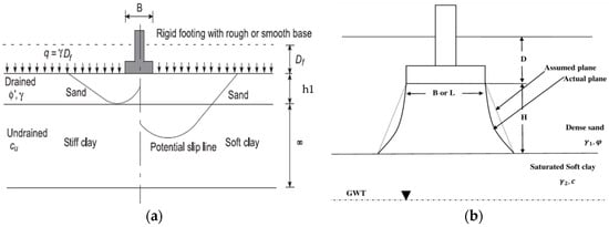
Figure 1.
(a) Potential failure mechanism for layered soil [2]; (b) potential failure in square or rectangular footing on layered soil [27].
Figure 1.
(a) Potential failure mechanism for layered soil [2]; (b) potential failure in square or rectangular footing on layered soil [27].
A study by Arushi et al. [27] was performed based on the punching shear mechanism followed by a projected area approach to propose an equation for the bearing capacity for square/rectangular footing resting on top of sandy soil overlaying a soft clay soil layer, as shown in Figure 1b. It was found that an increase in the friction angle also increased the soil’s bearing capacity, and the same was observed for an increase in cohesion value.
In a numerical study by Panwar and Dutta [7] on the bearing capacity of layered sand, it was determined that an increase in footing height-to-width ratio to about 1.75 resulted in increasing the bearing capacity of the soil; however, beyond this point, negligible effect was noticed. Following this, Rakesh et al. [21] proposed a bearing capacity equation for rectangular footing laid on layered sand with inclined loading using numerical analysis and results agreed well with previous studies. Nonlinear finite element analysis [3] was performed using ABAQUS for a layered soil medium (clay over sandy soil) underlying a strip footing. Results deduced that a higher amount of clay leads to a significant reduction in the ultimate bearing capacity and increase in soil settlement under the footing.
Based on the reviewed literature, it was found that geotechnical engineers currently design foundations situated on layered soil. Yet, most lab-based studies emphasize the investigation of a single homogenous continuum [3]. Hence, further research is required to study the effect of loading on layered soil (sandy soil overlaying clayey soil). Thus, this research aims to investigate the FE analysis (using ABAQUS software) of the bearing capacity of sandy soil overlaying clayey soil with an applied loading from strip footing. Plane strain conditions are assumed (the length of the footing is greater compared to its width), and only half of the footing system is modeled, owing to system’s symmetry.
2. Research Methodology
For finite element modeling, Drucker–Prager parameters were input for sandy soil, and Mohr–Coulomb parameters were added for the clay layer. Plane strain considerations utilize Equations (1) and (2) for the conversion of Mohr–Coulomb and Drucker–Prager parameters to each other [3] as follows:
where ′ stands for angle of internal friction and d′ stands for cohesion in Drucker–Prager model. In the study by Mosadegh and Nikraz [3], in a two-layer soil compared to a one-layer soil, the bearing capacity reduced dramatically to <70% of its value by adding the clay thickness of h1/B = 0.15 on top of the sand. Also, it was found that, as the depth of the clay increased, bearing capacity values were reduced, showing that the top layer mainly controls the bearing capacity value. In addition, it was noticed that, for smaller values of h1, the failure mechanism goes to the bottom layer.
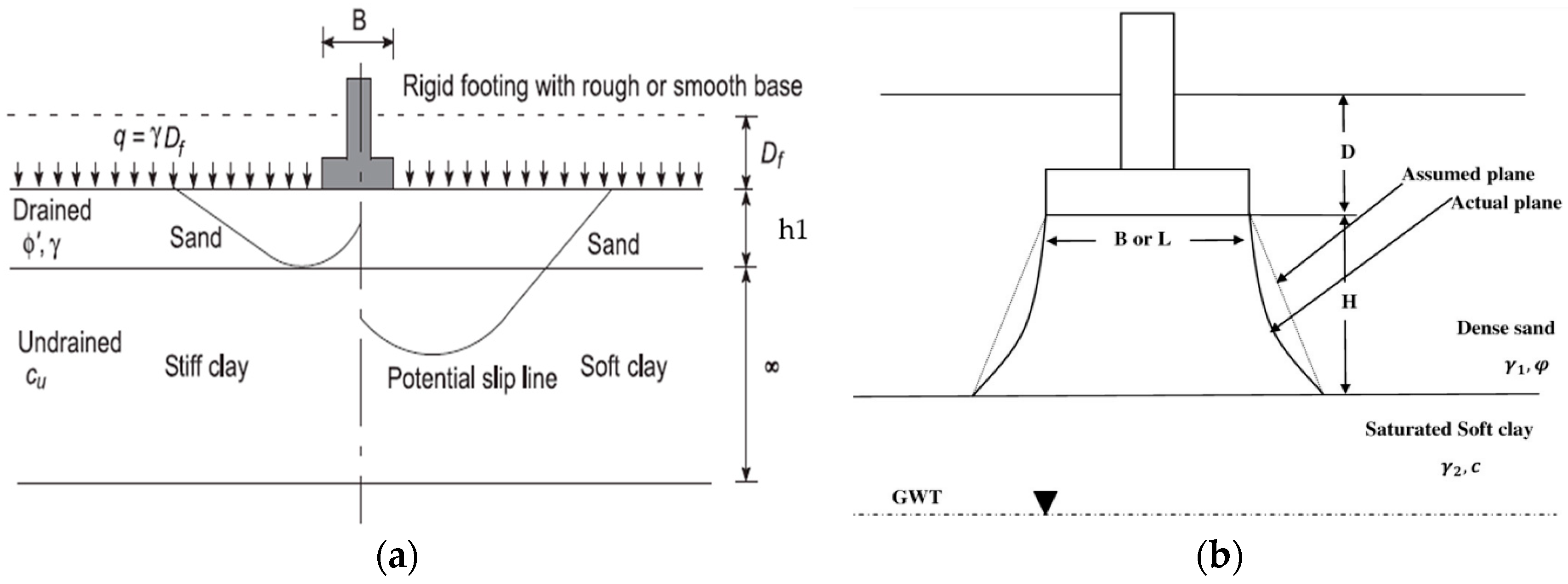
The current model comprises footing resting on two layered soil (sandy soil overlaying clay layer) with 3000 mm footing width (B), and the thickness of the sandy soil layer is considered as h1 (as shown in Figure 2). Figure 2 shows the problem definition with sandy soil being the top soil layer and clayey soil being the bottom soil layer of the layered soil system. Soil properties can be seen in Table 1. The effect of the thickness, unit weight and modulus of the elasticity of sandy soil, as well as the cohesion of clay on the ultimate bearing capacity of layered soil, are studied. To investigate the effect of sandy soil thickness, models with different h1/B ratios (0.15, 0.5, 1.0, 1.5, and 2.0) are examined. Different sandy soil layer thicknesses analyzed are 450 mm, 1500 mm, 3000 mm, 4500 mm, and 6000 mm. Additional models were also prepared to study the influence of the unit weight and modulus of the elasticity of sandy soil, as well as the cohesion of the clay layer on the ultimate soil bearing capacity.
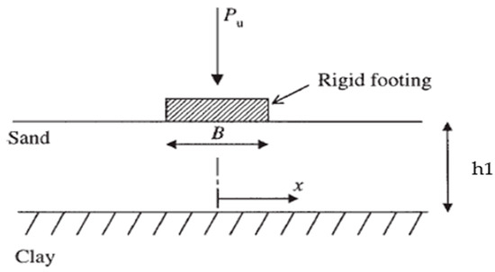
Figure 2.
Problem Illustration (Adapted with permission from [40]).

Table 1.
Material Properties of the Soil [3].
In order to reduce the influence of boundary conditions, sufficiently large model was prepared. For parametric study, two sandy soil thickness models were analyzed, namely, the 3000 mm model (or h1/B = 1.0) with sandy soil unit weights of 14 kN/m3, 15 kN/m3, and 18 kN/m3 and 6000 mm model (or h1/B = 2.0) with sandy soil unit weights of 14 kN/m3, 17 kN/m3, and 18 kN/m3. For studying the effect of the modulus of elasticity (E) of sandy soil on the bearing capacity, a 6000 mm model (or h1/B = 2.0) with E values of 10 MPa, 15 MPa, and 18 MPa was analyzed. To examine the effect of the cohesion on the bearing capacity of soil, two models were analyzed: 450 mm (h1/B = 0.15) and 6000 mm (h1/B = 2.0) models with cohesion values of 20 kPa, 25 kPa, and 30 kPa.
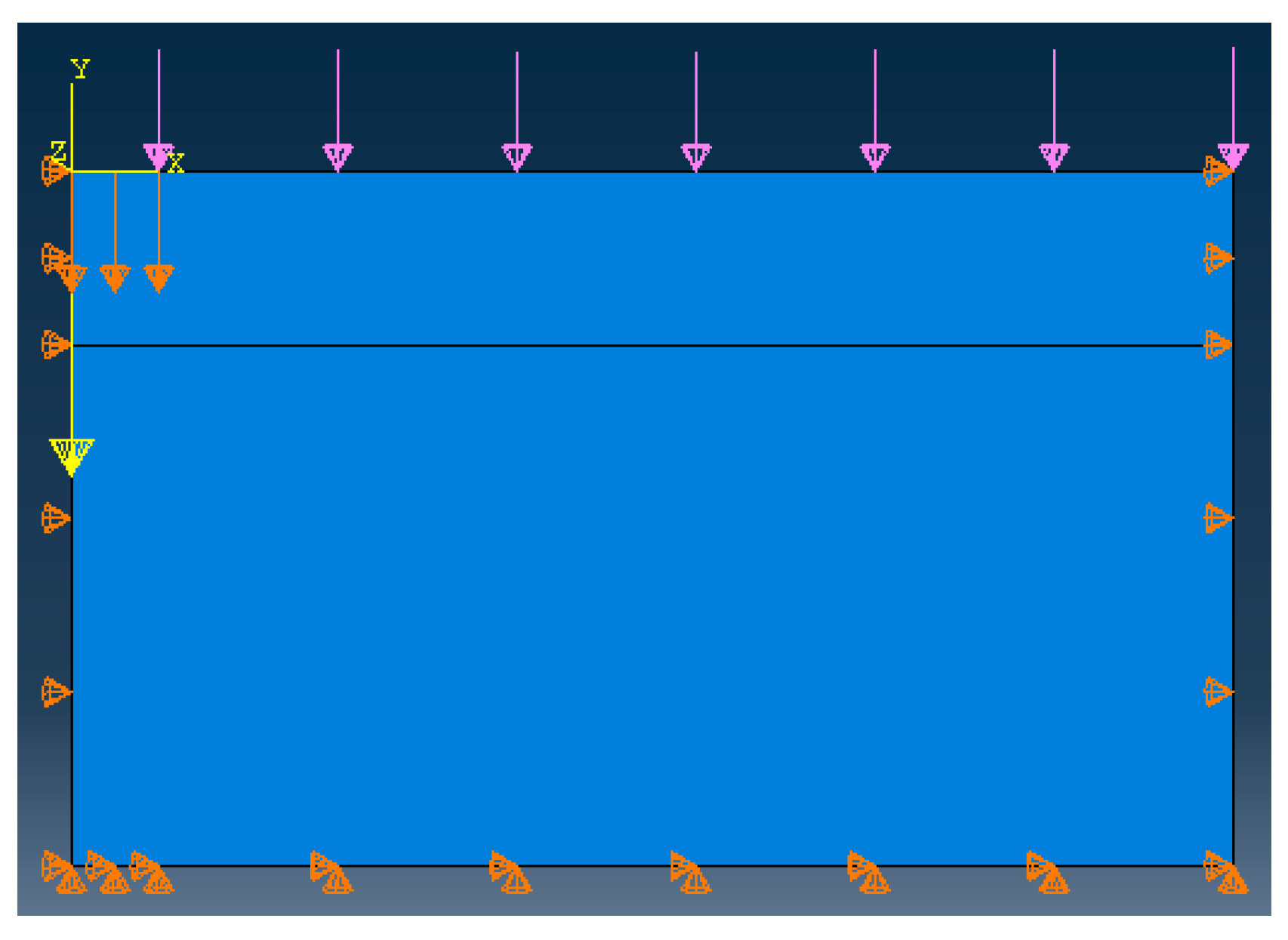
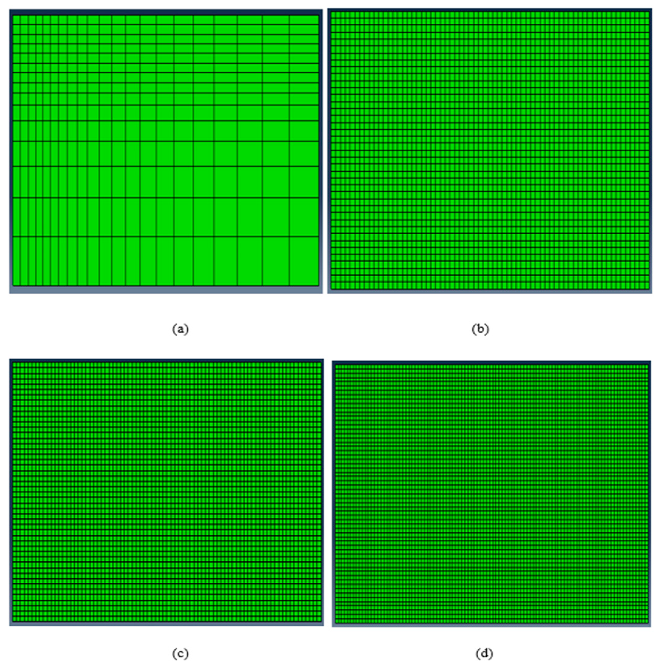
Moreover, mesh sensitivity analysis was also performed. Figure 3 presents the boundary conditions and loads being applied to the model. For the bottom boundary, horizontal and vertical movements are fixed. For vertical sides, horizontal movement is restricted and vertical movement is allowed. For load application, three different steps were utilized. (i) Surcharge load (q) of 9.60 kPa was applied, (ii) geostatic effect was applied to consider the effect of gravity loads, and (iii) for the elastic settlement of the footing, a vertical step was added to the model. Mesh sensitivity analysis was done to obtain an optimal model with accurate results. Meshing was refined for the soil layers closer to footing due to the higher concentration of stresses in this region. Additional mesh refinement would lead to higher computational cost. Therefore, mesh sensitivity analysis becomes essential to evaluate and obtain the most optimum mesh size for the model. Figure 4 shows different mesh sizes analyzed for mesh sensitivity analysis.
Figure 3.
ABAQUS model representation with the applied boundary conditions and loads.

Figure 4.
Various mesh sizes for mesh sensitivity analysis: (a) from 0.45 to 2.00 m (=450 to 2000 mm), (b) 0.30 m (300 mm), (c) 0.25 m (250 mm), and (d) 0.20 m (200 mm).
3. Results and Discussion
This section reports all results and mesh sensitivity analysis of the study. Firstly, model validation and mesh sensitivity analysis results were discussed. Next, the effect of sandy soil layer thickness, plastic shear, and vertical stress distribution were discussed. Lastly, the effect of sandy soil’s unit weight, the modulus of elasticity of sandy soil, and the clay layer’s cohesion on soil’s bearing capacity was discussed in detail.
3.1. Verification and Mesh Sensitivity Analysis of FE Model
FE model was validated with results of Mosadegh and Nikraz [3], since it was analyzed with clay layer over sandy soil layer; therefore, similar FE models were prepared, analyzed and the results were compared. Figure 5a shows the values of the ultimate bearing capacity for different clay-over-sandy soil thicknesses. Here, h1 is the clay (top layer) thickness and B is the footing width (=3000 mm). The different clay layer thicknesses used were 450 mm (h1/B = 0.15), 1500 mm (h1/B = 0.5), 3000 mm (h1/B = 1.0), 4500 mm (h1/B = 1.5), and 6000 mm (h1/B = 2.0). FE model results are nearly equal to those provided by [3], with slight deviations, and thus, the results of FE model were validated. Additionally, as expected, Figure 5a shows that the bearing capacity of layered soil decreases with an increase in clay layer thickness because clay is a weaker type of soil. The FE model results were further validated by comparing plastic shear strain values from the model with values reported in Mosadegh and Nikraz [3]. Figure 5b shows that plastic shear strain decreases as clay layer thickness increases and this further validates the model since FE results are quite close to plastic shear strain values, with acceptable deviations.
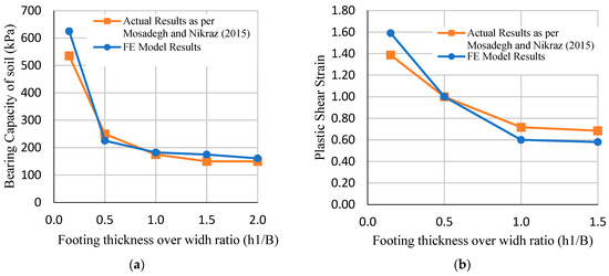
Figure 5.
(a) Bearing capacity and (b) plastic shear strain of soil with clayey soil overlaying sandy soil for FE model validation with [3].
Thereafter, mesh sensitivity analysis for the FE model with clayey soil over sandy soil was performed to obtain the most optimum mesh size for the model. For the selection of the most optimum mesh size, the model with a clay thickness of 1500 mm (h1/B = 0.5) was studied with different mesh sizes, as shown in Figure 4. For each mesh size, bearing capacity, plastic shear strain, and run time (in seconds) were analyzed, as shown in Table 2. The first mesh size ranged from 0.45 to 2.00 m (450 to 2000 mm), and as per the results, both the bearing capacity and plastic shear strain were low compared to results reported by Mosadegh and Nikraz [3]; however, it took the least amount of run time. For the second model with 0.25 m (250 mm) mesh size, results were not significantly close to actual reported results, and the run time was short. The third model used 0.20 m (200 mm) mesh size in which the bearing capacity and plastic shear strain values were significantly closer to the actual values reported by Mosadegh and Nikraz [3], and the run time was not excessively long. The fourth model had 0.15 m (150 mm) mesh size (finest); however, the bearing capacity and plastic shear strain values did not match the actual results, and the run time was found to be quite long compared to other mesh sizes. Therefore, the third model with 0.20 m (200 mm) mesh size seemed to be the most optimum as the plastic shear strain value matched the actual result, and it had a closer bearing capacity value as well. This demonstrates that the mesh size achieved convergence for the model. However, the third model was found to be significantly more accurate in comparison to other models, so increasing the number of elements beyond the mesh size of 0.20 m (200 mm) would not result in the further improvement of results without increasing the run time significantly. Hence, the mesh size of 0.20 m (200 mm) was considered as the optimum mesh size for this model.
Table 2.
Mesh Sensitivity Analysis Results of FE Model with Clayey Soil over Sandy Soil.
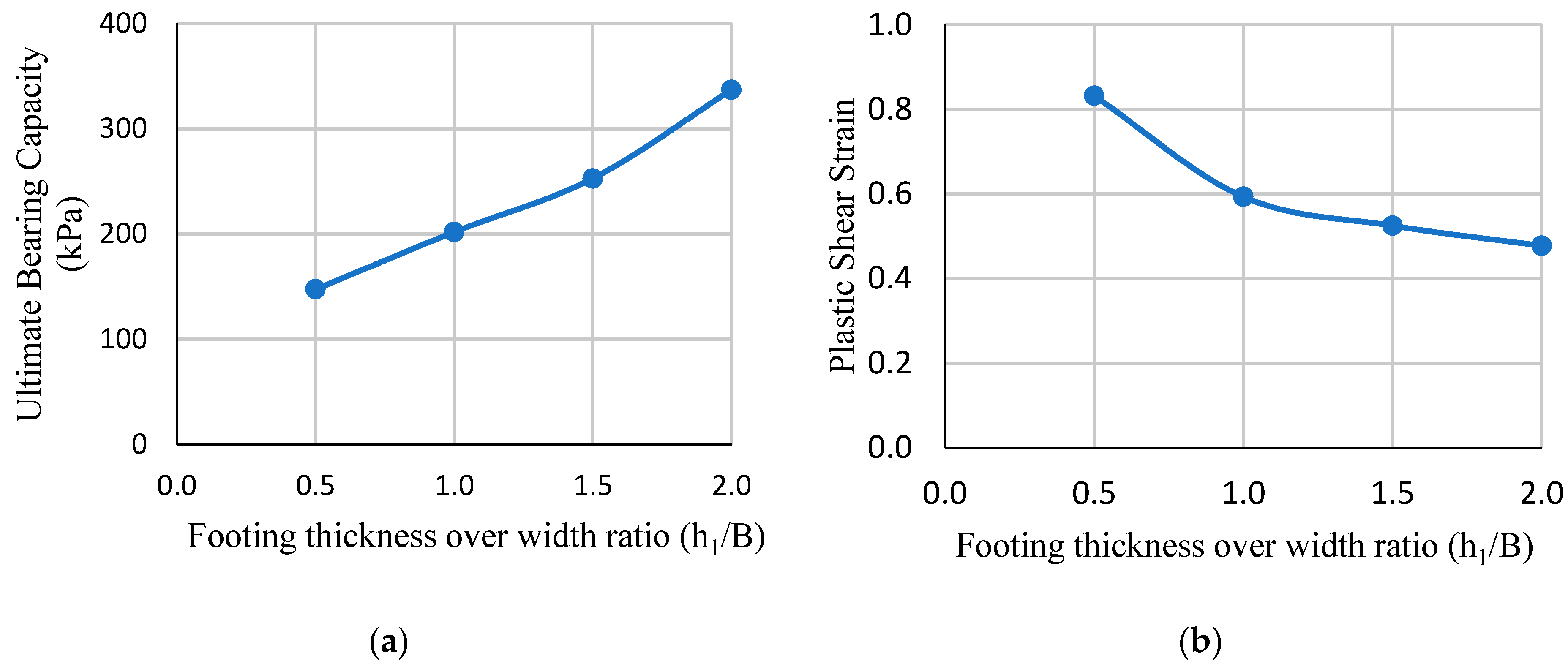
By utilizing the same validated FE model and flipping the layer properties, an investigation of the sandy soil overlaying the clayey soil layer was conducted and studied. Figure 6a presents the ultimate bearing capacity for the layered soil case of the sandy soil overlaying clay layer. It clearly shows that an increase in sandy soil layer thickness (or reduction in clay layer thickness) leads to an increase in the bearing capacity of the soil. Similar to Figure 5b, Figure 6b also demonstrates that plastic shear strain decreases as the sandy soil layer increases.

Figure 6.
(a) Bearing capacity and (b) plastic shear strain of soil with sandy soil overlaying clayey soil medium.
Table 3 presents the mesh sensitivity analysis of the FE model with sandy soil (thickness = 3000 mm) overlaying clay soil. The model with 0.20 m (200 mm) mesh size was selected based on optimum results in the previous analysis. However, to check the accuracy of the most optimum model, four models with different mesh sizes were analyzed and compared to it. For the first model, a mesh size of 0.45 to 2.00 m (450 to 2000 mm) was used, the bearing capacity was closer to the model with 0.20 m (200 mm) mesh size and it had the shortest run time. However, the plastic shear strain value was far from the value of the 0.20 m (200 mm) meshed model. For the second model, a mesh size of 0.30 m (300 mm) was used, and the bearing capacity and plastic shear strain values were found to be far from the selected model. For the third model, a mesh size of 0.25 m (250 mm) was used, and the bearing capacity was found to be far from the selected model; however, the plastic shear strain value was closer to the selected model. A model with a mesh size smaller than 0.20 m (200 mm) was also prepared, but it crashed due to the long run time. Nonetheless, a mesh size of 0.20 m (200 mm) was considered to be the most optimal model with accurate results for layered soil based on the previous analysis (sand overlaying clay layer).
Table 3.
Mesh Sensitivity Analysis Results of FE model with Sandy Soil over Clayey Soil.
3.2. Effect of Sandy Soil Layer Thickness on Bearing Capacity and Soil Settlement
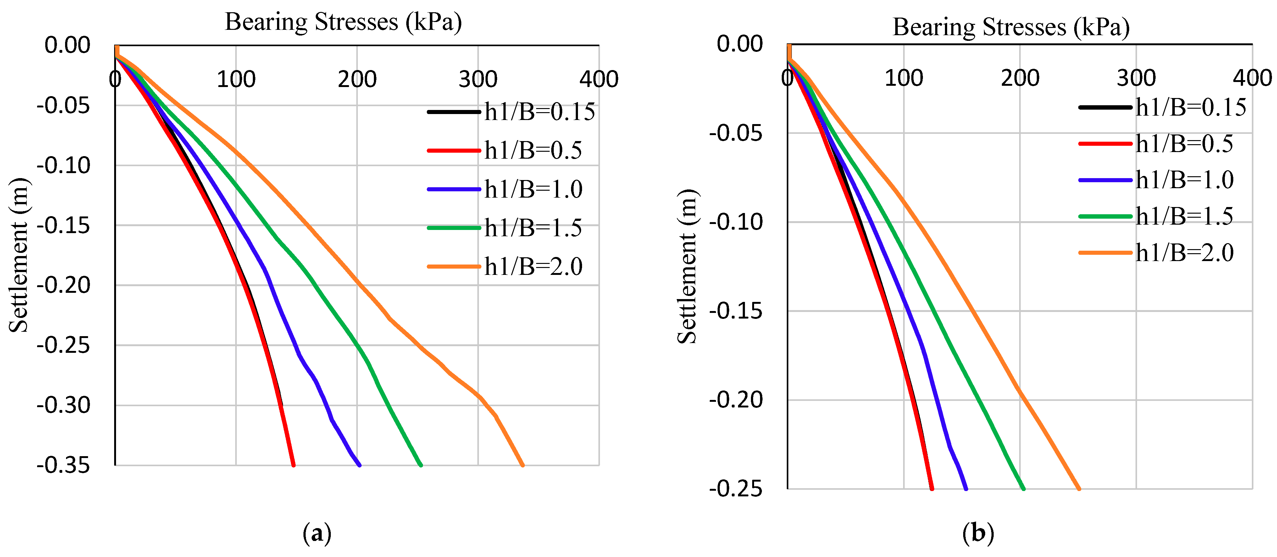
The soil becomes stronger with an increase in depth and the elastic settlement of the footing. To study and investigate this claim, the bearing capacities at different sandy soil layer thicknesses and elastic settlements were analyzed and the results are presented in Figure 7 and Table 4. As mentioned, the different sandy soil thicknesses used for this analysis were 450 mm (h1/B = 0.15), 1500 mm (h1/B = 0.5), 3000 mm (h1/B = 1.0), 4500 mm (h1/B = 1.5), and 6000 mm (h1/B = 2.0) and was performed for two different elastic settlements (350 mm and 250 mm).
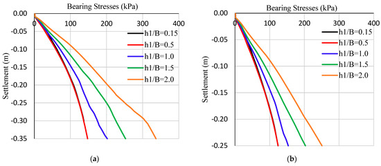
Figure 7.
Ultimate bearing capacity with different sandy soil thicknesses and elastic settlement of (a) 350 mm, and (b) 250 mm for sandy soil overlaying clayey soil model.
Table 4.
FE Model Parametric Analysis Results of the Ultimate Bearing Capacities of Sandy Soil Overlaying Clayey Soil.
3.2.1. Footing Behavior at Elastic Settlement of 350 mm
Figure 7a shows the bearing capacity values for all sandy soil thicknesses with an elastic settlement of 350 mm. It clearly shows that the bearing capacity increases with an increase in sandy soil thickness and similar results were drawn by Das et al. [20]. It also deduces that soil bearing capacity increases with an increased settlement, which shows that soil becomes stronger with an increase in depth underground. The ultimate bearing capacity of soil is the maximum stress value of each curve shown in the figure. For a 450 mm (h1/B = 0.15) thickness of sandy soil, the bearing capacity was 137.14 kPa at 300 mm settlement (=0.3 m settlement in Figure 7a) and the model failed beyond that, as the bearing stress curve stops. This shows that the sandy soil layer is too thin and that layered soil is weak as the majority of the layered soil is composed of clay, which is a weaker soil type. For h1/B = 0.5, the bearing stress was found to be about 147.45 kPa with 350 mm elastic settlement of footing and matched precisely with h1/B = 0.15 curve till a settlement value of 300 mm, which showed no significant increase in the bearing capacity between two curves for the same value of the initial footing settlement up to a settlement value of 300 mm. However, the h1/B = 0.5 curve had higher sandy soil layer thickness, so soil became stronger with the ability to achieve higher ultimate bearing capacity along with the capability to undergo a 350 mm settlement. Therefore, there was an improvement of about 7.52% in the ultimate bearing capacity of soil with an increase in sandy soil thickness of 1050 mm. Soil bearing capacities for h1/B = 1.0, h1/B = 1.5, and h1/B = 2.0 were 201.91 kPa, 252.74 kPa, and 336.84 kPa, respectively. Therefore, about a 25.17% and 66.83% improvement in soil bearing capacities was observed when sandy soil layer thickness was increased from 3000 mm to 4500 mm and 6000 mm, respectively. Moreover, about a 145.62% increase in the ultimate bearing capacity was obtained with an increase in sandy soil thickness from 450 mm to 6000 mm. Hence, an increase in the sandy soil layer thickness improves the layered soil’s ultimate bearing capacity.
3.2.2. Footing Behavior at Elastic Settlement of 250 mm
Figure 7b shows the bearing capacity values for all sandy soil thicknesses with an elastic settlement of 250 mm. Similar to Figure 7a, Figure 7b demonstrates that an increase in sandy soil layer thickness leads to an increase in the layered soil’s ultimate bearing capacity, and the bearing capacity also increases with an increase in soil settlement. It was noticed that negligible improvement was observed in the ultimate bearing capacity of soil with an increase in sandy soil layer thickness from 450 mm to 1500 mm, but continuous improvement in soil bearing stress was noticed after h1/B = 0.5. Increasing the sandy soil layer thickness over the footing width (h1/B) ratio from 0.15 to 2.0 improved the ultimate bearing capacities with elastic settlements of 250 mm by 101.66%.
It is also evident from Table 4 and Figure 7 that ultimate the soil bearing capacities of a 350 mm footing settlement are higher compared to a 250 mm settlement with an increment of about 34.47% at h1/B = 2.0. In addition, the results of both figures show that the ultimate bearing capacity increases with increases in soil settlement, since soil becomes stronger with an increase in depth. Additionally, Figure 7a,b conclude that once h1 ≥ B, soil stress increases at a higher rate in comparison with the cases when h1 ≤ B.
3.3. Plastic Shear and Vertical Stress Distribution
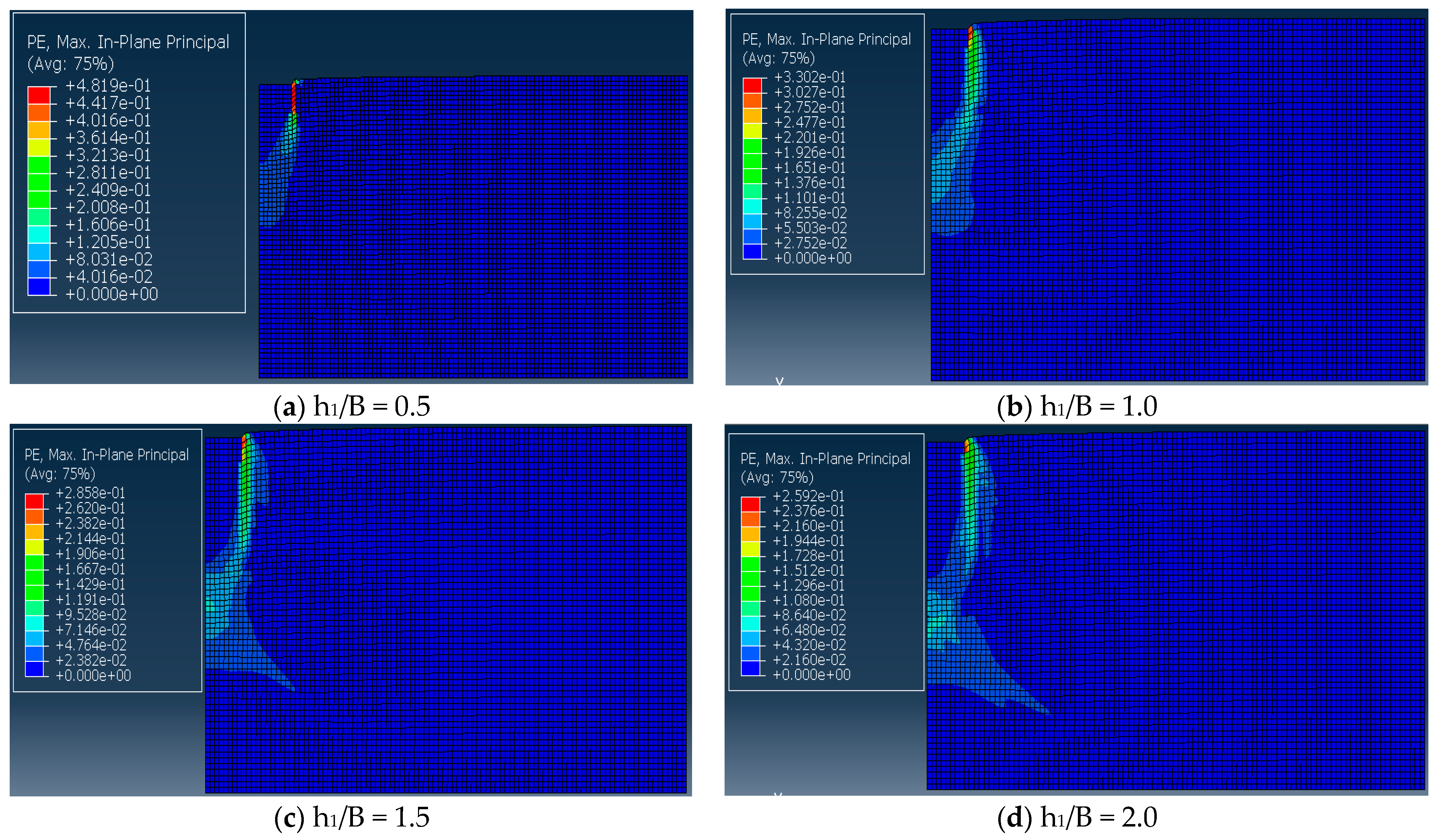
In this subsection, the plastic shear distribution for various thicknesses of the sandy soil layer is presented (Figure 8). For these models, the elastic footing settlement used was 350 mm with the spreading of shear stress along the depth of soil demonstrated. As noticed from Figure 8, it can be concluded that an increase in the sandy soil layer (top layer) thickness in layered soil leads to a higher spread of shear stress distribution along its depth. Moreover, it was found that stress mainly lies in the sandy soil region for higher sandy soil layer thicknesses, demonstrating that the layered soil case started to convert into a homogeneous soil case.
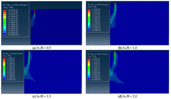
Figure 8.
Plastic shear distribution for various sandy soil thicknesses: (a) h1/B = 0.5, (b) h1/B = 1.0, (c) h1/B = 1.5, and (d) h1/B = 2.0 in layered soil (sandy soil overlaying clayey soil).
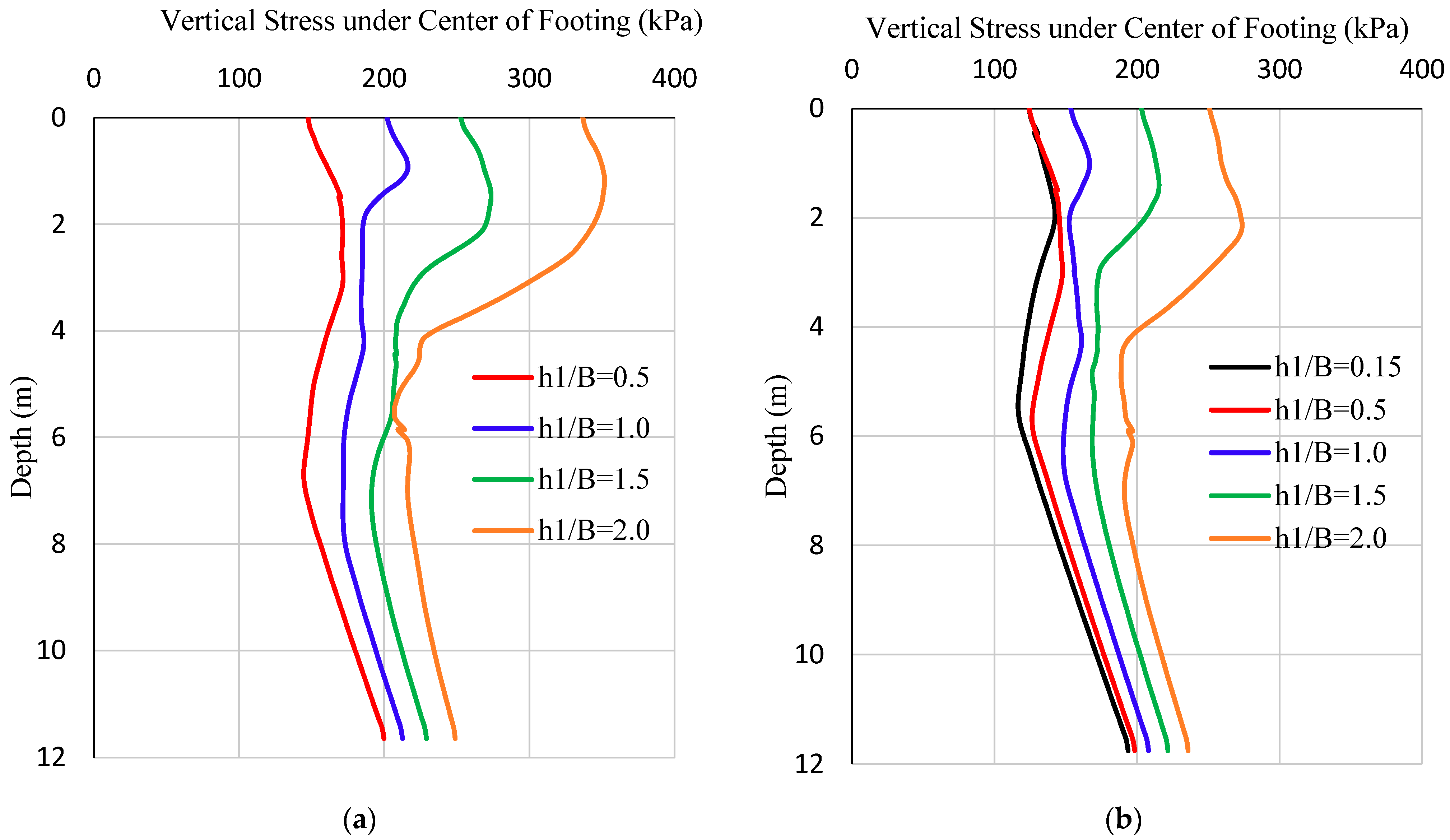
The vertical stress distribution along the depth of soil for different h1/B ratios is shown in Figure 9. Referring to Figure 9a with an elastic settlement of 350 mm, the case of h1/B = 0.15 could not be plotted since it failed at an elastic settlement of 300 mm. Vertical stress value at depth 0 mm (intersection point of the footing center and top soil layer) is the layered soil’s ultimate bearing capacity value and is at the soil-footing interface. Figure 9a further validates that an increase in sandy soil layer thickness leads to the higher bearing capacity of soil and higher soil stresses, as h1/B = 2.0 has the maximum soil stress values among all h1/B curves. Figure 9b corresponds to an elastic settlement of 250 mm and similar results were observed as Figure 9a. It can be concluded that the layered soil’s ultimate soil bearing capacity occurs at the soil-footing interface. Moreover, similar to Figure 9a, Figure 9b displays that an increase in sandy soil layer thickness leads to a higher bearing capacity of soil and higher soil stresses, as h1/B = 2.0 has the maximum soil stress values among all h1/B curves. Figure 9a,b both portray that for h1/B ≥ 1.0, the vertical stress value has higher stress variation and higher stress values along the depth compared to stress values of h1/B < 1.0.
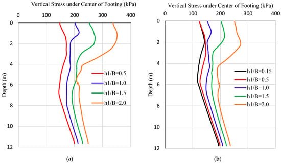
Figure 9.
Vertical stress distribution along the soil depth in layered soil (sandy soil overlaying clayey soil) with elastic footing settlement of (a) 350 mm, and (b) 250 mm.
3.4. Effect of Sandy Soil Unit Weight on Bearing Capacity and Soil Settlement
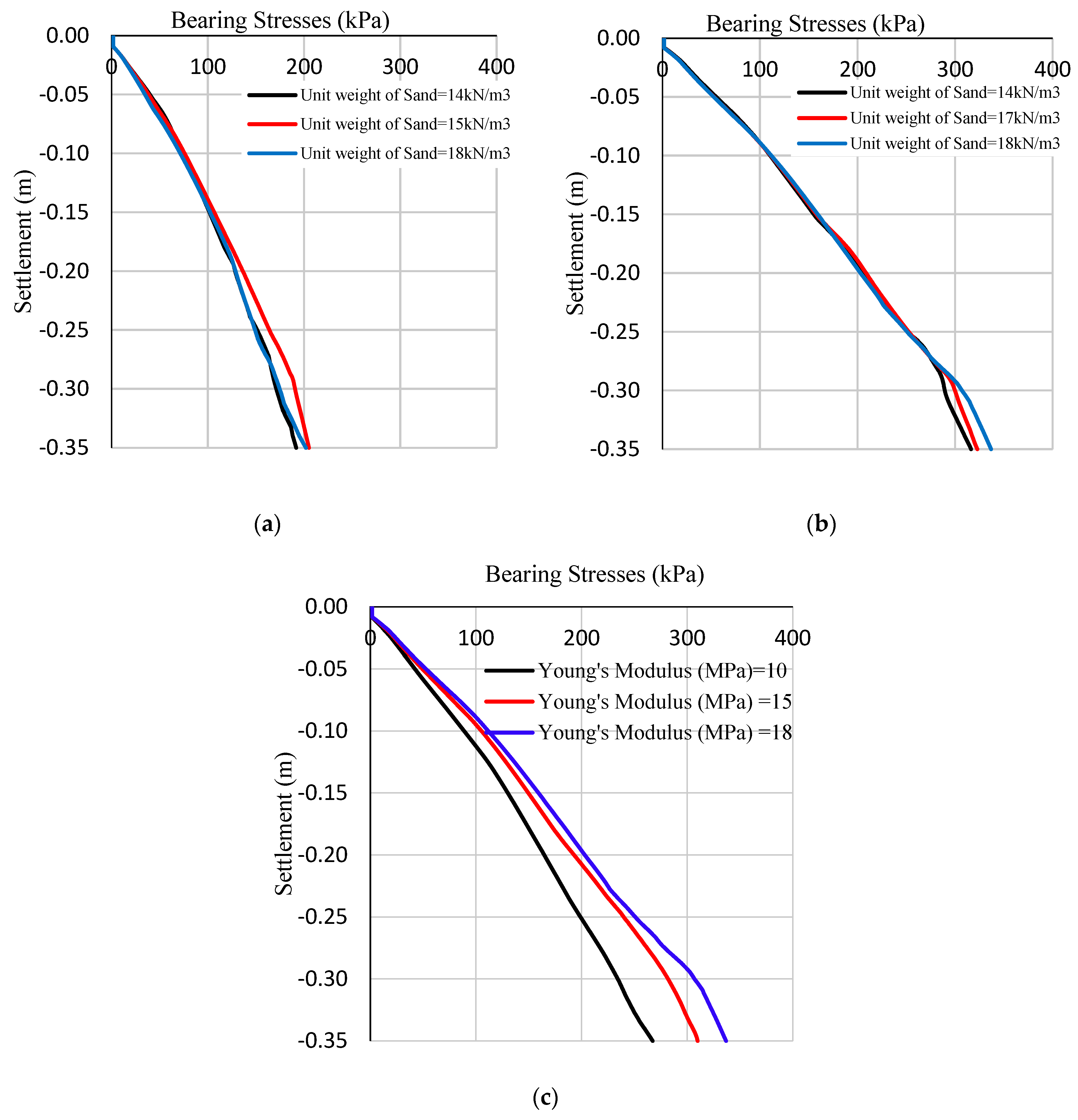
Since soil characteristics play a key role in establishing the ultimate bearing capacity of soil, an investigation of the influence of some vital soil parameters on bearing capacity is required for an in-depth understanding of the layered soil case. Figure 10a,b present the parametric study’s results on the effect of sandy soil’s unit weight on the bearing capacity of soil for h1/B equal to 1.0 and 2.0 with a 350 mm settlement, and their bearing capacities have been reported in Table 4. For h1/B = 1.0, the effect of three sandy soil unit weights (14 kN/m3, 15 kN/m3, and 18 kN/m3) on bearing capacity were analyzed as shown in Figure 10a, in which a slight increment in soil bearing capacity was noticed with an increase in sandy soil unit weight. Also, bearing capacity increased by 6.91% when the sandy soil’s unit weight was increased from 14 kN/m3 to 15 kN/m3. However, further increase in sandy soil unit weight from 15 kN/m3 to 18 kN/m3 slightly reduced the bearing capacity by 1.52%. Hence, the positive effect of increasing the sandy soil unit weight is seen only until a threshold value for h1/B = 1.0.
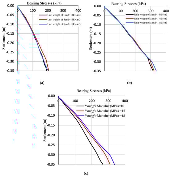
Figure 10.
Effect of sandy soil (a) unit weight with h1/B = 1.0, (b) unit weight with h1/B = 2.0, and (c) modulus of elasticity with h1/B = 2.0 on the bearing capacity of layered soil (sandy soil overlaying clayey soil) with settlement of 350 mm.
Figure 10b presents the effect of sandy soil unit weight on the bearing capacity for h1/B = 2.0 with a settlement of 350 mm. Three sandy soil unit weights were used for this analysis. Figure 10b shows a slight increment in the bearing capacity of soil with an increase in sandy soil unit weight observed, with the bearing capacity at sandy soil’s unit weight of 14 kN/m3, 17 kN/m3, and 18 kN/m3 being 316.40, 322.83, and 336.84 kPa, respectively. An increment in the bearing capacity of about 2.03% and 6.46% was observed with an increase in sandy soil’s unit weight from 14 kN/m3 to 17 kN/m3 and 18 kN/m3, respectively. Thus, unlike the h1/B = 1.0 case, h1/B = 2.0 deduces that an increase in sandy soil’s unit weight slightly improves the ultimate bearing capacity of layered soil. Hence, Figure 10a,b show that increased sandy soil unit weight leads to a slight improvement in the bearing capacity of layered soil for higher sandy soil thicknesses. However, this improvement in the bearing capacity was relatively small at smaller sandy soil thicknesses. Therefore, sandy soil unit weight slightly impacts the bearing capacity of layered soil for lower h1/B ratios. However, h1/B > 2.0 may show a more significant effect of sandy soil’s unit weight on the bearing capacity of layered soil. Since h1/B > 2.0 means the sandy soil layer thickness is higher than clay soil and the effect of the sandy soil will have more impact on bearing capacity than clay soil. Moreover, even Figure 10a,b shows that with an increase in settlement, the bearing stress of the soil increases.
3.5. Effect of Modulus of Elasticity of Sandy Soil on Bearing Capacity
The effect of the different values of the modulus of the elasticity of sandy soil (10 MPa, 15 MPa, and 18 MPa) on bearing capacity for h1/B = 2.0 was also studied and their results are provided in Figure 10c and Table 4. It shows that an increase in the modulus of elasticity of sandy soil causes an increase in the bearing capacity of soil. Bearing capacity values at 10 MPa, 15 MPa, and 18 MPa were determined to be about 267.36 kPa, 309.89 kPa, and 336.84 kPa, respectively. Hence, about a 15.91% and 25.99% improvement had occurred in the bearing capacity of soil for h1/B = 2.0 with an increase in the sandy soil modulus of elasticity from 10 MPa to 15 MPa and 18 MPa, respectively. This shows that, with an increased modulus of elasticity, the soil becomes stronger, and the bearing capacity significantly improves.
3.6. Effect of Cohesion on Bearing Capacity and Soil Settlement
Table 4 and Figure 11 show the effect of different cohesive strengths of the clay layer (20 kPa, 25 kPa, and 30 kPa) on the soil bearing capacity for h1/B = 0.15 with a settlement of 300 mm and h1/B = 2.0 with a settlement of 350 mm. Clay is a weaker type of soil, and the shear strength of clay mainly depends on cohesion; hence, an increase in the cohesive strength of clay should make the soil stronger. This can be observed clearly in Figure 11a, as increased cohesion led to an increased soil bearing capacity. The bearing capacity values at 20 kPa, 25 kPa, and 30 kPa were determined to be about 122.71 kPa, 137.14 kPa, and 152.54 kPa, respectively. Therefore, about a 11.76% and 24.31% increase in soil bearing capacity occurred for h1/B = 0.15 with an increase in cohesive strength from 20 kPa to 25 kPa and 30 kPa, respectively. So, an increase in cohesive strength increases soil bearing capacity, and similar conclusions were drawn by Das et al. [20]. This validates that an increase in soil strength improves the bearing capacity of soil. As seen in Figure 11b, only a slight improvement in the bearing capacity of layered soil was observed as the bearing capacity values at cohesion values of 20 kPa, 25 kPa, and 30 kPa were 322.79 kPa, 336.84 kPa, and 334.00 kPa, respectively. Hence, only about a 4.35% and 3.47% improvement in soil bearing capacity was seen for h1/B = 2.0 model, respectively, with an increase in cohesion values from 20 kPa to 25 kPa, and 30 kPa. This is because, in the h1/B = 2.0 model, the clay layer thickness is small compared to the h1/B = 0.15 model. So, to significantly impact the bearing capacity of the soil, the clayey soil layer needs to be very thick. This proves that clay is a weaker type of soil, so higher clay layer thickness is required to significantly impact the soil’s ultimate bearing capacity. Moreover, the cohesive strength of clay improved the bearing capacity up to 25 kPa, beyond which a slight drop in the bearing capacity was noticed for the thinner clay layer model. Hence, it can be concluded that, at lower clay layer thickness, the positive effect of cohesive strength on bearing capacity is observed.
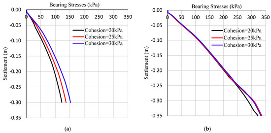
Figure 11.
Effect of clayey soil cohesion on the ultimate bearing capacity of layered soil (sandy soil overlaying clayey soil) for (a) h1/B = 0.15 with a settlement of 300 mm, and (b) h1/B = 2.0 with a settlement of 350 mm.
4. Conclusions
Based on the research study conducted and after performing various analyses to understand the ultimate bearing capacity of sandy soil overlaying clayey soil medium, the following conclusions were drawn:
- An increase in sandy soil layer thickness over footing width (h1/B) ratio and elastic settlement values resulted in an improvement of the ultimate bearing capacities. This could be attributed to the fact that soil becomes stronger with increased depth;
- Increasing the sandy soil layer thickness over footing width (h1/B) ratio from 0.15 to 2.0 increased the ultimate bearing capacities with elastic settlements of 350 mm and 250 mm by 145.62% and 101.66%, respectively;
- When sandy soil layer thickness (h1) becomes greater than or equal to the width of the footing (B), the bearing stress of the soil strengthens at a higher rate when compared to lower sandy soil layer thickness (h1) values;
- Higher top layer (sandy soil) thickness leads to larger shear stress distribution along its depth and converts the layered soil medium into a homogeneous soil case (as the majority of the shear stress lies in the top layer);
- At a settlement of 350 mm, bearing capacity increased by 6.91% and 5.28% for h1/B = 1.0 when the sandy soil’s unit weight was increased from 14 kN/m3 to 15 kN/m3 and 18 kN/m3, respectively. For h1/B = 2.0, the bearing capacity increased by 2.03% and 6.46%, with an increase in the sandy soil’s unit weight from 14 kN/m3 to 17 kN/m3 and 18 kN/m3, respectively;
- At h1/B > 1.0, higher ultimate bearing capacity occurs with an increase in the sandy soil’s unit weight and elastic modulus, while at h1/B ≤ 1.0, the ultimate bearing capacity increases till a threshold value of the sandy soil unit weight;
- At a settlement of 350 mm, an increase in the sandy soil modulus of elasticity from 10 MPa to 15 MPa and 18 MPa resulted in improving the bearing capacity by about 15.91% and 25.99%, respectively;
- At h1/B ≤ 1.0, higher ultimate bearing capacity occurs with an increase in the cohesive strength of clayey soil, while at h1/B > 1.0, the ultimate bearing capacity increases until a threshold value of cohesive strength of clay;
- An increase in clayey soil’s cohesive strength from 20 kPa to 30 kPa increased the soil bearing capacity for h1/B = 0.15 (settlement of 300 mm) and h1/B = 2.0 (settlement of 350 mm) by 24.31% and 3.47%, respectively;
- Bearing capacity was significantly improved with an increased modulus of the elasticity of sand. In addition, for lower clay layer thickness, the positive effect of cohesive strength on the bearing capacity was observed.
Author Contributions
Conceptualization, S.B., M.A. and F.A.; methodology, S.B., M.A., F.A., R.V., P.V.A., N.A.-L. and A.K. software, S.B., M.A., F.A. and P.V.A.; validation, S.B., M.A., F.A., R.V. and P.V.A.; formal analysis, S.B., F.A., R.V., P.V.A., N.A.-L. and A.K.; investigation, S.B., M.A., F.A., R.V., P.V.A., N.A.-L. and A.K.; resources, M.A. and F.A.; data curation, S.B., M.A., F.A. and R.V.; writing—original draft preparation, S.B., M.A., F.A., N.A.-L. and A.K.; writing—review and editing, M.A., F.A., R.V. and P.A; visualization, S.B., M.A. and F.A.; supervision, M.A. and F.A.; project administration, M.A. and F.A.; funding acquisition, M.A. and F.A. All authors have read and agreed to the published version of the manuscript.
Funding
This research was financially supported by the American University of Sharjah (AUS) through the Open Access Program (OAP). FRG20-M-61.
Data Availability Statement
Data are available from the corresponding author upon reasonable request.
Conflicts of Interest
The authors declare no conflicts of interest.
References
- Haghbin, M. Bearing Capacity of Strip Footings Resting on Granular Soil Overlying Soft Clay. Int. J. Civil Eng. 2016, 14, 467–477. [Google Scholar] [CrossRef]
- Shiau, J.S.; Lyamin, A.V.; Sloan, S.W. Bearing capacity of a sand layer on clay by finite element limit analysis. Can. Geotech. J. 2003, 4, 900–915. [Google Scholar] [CrossRef]
- Mosadegh, A.; Nikraz, H. Bearing Capacity Evaluation of Footing on a Layered-Soil Using ABAQUS. J. Earth Sci. Clim. Chang. 2015, 6, 264. [Google Scholar]
- Quang, P.N.; Ohtsuka, S. Ultimate Bearing Capacity of Rigid Footing on Two-Layered Soils of Sand-Clay. Int. J. Geomech. 2021, 21, 04021115. [Google Scholar]
- Terzaghi, K.; Peak, R.B. Soil Mechanics in Engineering Practice; John Wiley: New York, NY, USA, 1948. [Google Scholar]
- Zheng, G.; Zhao, J.; Zhou, H.; Zhang, T. Ultimate Bearing Capacity of Strip Footings on Sand Overlying Clay under Inclined Loading. Comput. Geotech. 2019, 106, 266–273. [Google Scholar] [CrossRef]
- Panwar, V.; Dutta, R.K. Numerical Study of Ultimate Bearing Capacity of Rectangular Footing on Layered Sand. J. Achiev. Mater. Manuf. Eng. 2020, 101, 15–26. [Google Scholar] [CrossRef]
- Panwar, V.; Dutta, R.K. Development of Bearing Capacity Equation for Rectangular Footing under Inclined Loading on Layered Sand. Civ. Eng. Infrastruct. J. 2021, 56, 173–192. [Google Scholar]
- Afaq, A.; Aiman, A.; Usman, A.; Mohamed, E.; Farid, A. Prediction of columns with GFRP bars through Artificial Neural Network and ABAQUS. Structures 2022, 40, 247–255. [Google Scholar]
- Muhammad, K.; Farid, A. Nonlinear FE analysis of fiber reinforced cementitious matrix strengthened RC columns. In Computational Modelling of Concrete and Concrete Structures; CRC Press: Boca Raton, FL, USA, 2022; pp. 219–225. [Google Scholar]
- Khalil, A.; Elkafrawy, M.; Hawileh, R.; AlHamaydeh, M.; Abuzaid, W. Numerical Investigation of Flexural Behavior of Reinforced Concrete (RC) T-Beams Strengthened with Pre-Stressed Iron-Based (FeMnSiCrNi) Shape Memory Alloy Bars. J. Compos. Sci. 2023, 7, 258. [Google Scholar] [CrossRef]
- Elkafrawy, M.; Khalil, A.; AlHamaydeh, M.; Hawileh, R.; Abuzaid, W. Enhancing the Shear Capacity of RC Beams with Web Openings in Shear Zones Using Pre-Stressed Fe-SMA Bars: Numerical Study. Buildings 2023, 13, 1505. [Google Scholar] [CrossRef]
- Reza, Z.M.; Vahid, R.; Ehsan, I. Evaluation on Bearing Capacity of Ring Foundations on two-Layered Soil. World Acad. Sci. Eng. Technol. 2012, 61, 1108–1112. [Google Scholar]
- Farid, A.; Chahmi, O.; Yousef, A.; Haya, H.M.; Hakem, A. FE modeling of concrete beams and columns reinforced with FRP composites. Def. Technol. 2021, 17, 1–14. [Google Scholar]
- Selim, A.H.; Fardin, M.; Jamal, A.A.; Rami, A.H.; Farid, A.; Muhammad, K. Finite Element Modeling of Engineered Cementitious Composite (ECC) Prisms and Beams. In Proceedings of the Advances in Science and Engineering Technology International Conferences, ASET, Dubai, United Arab Emirates, 21–24 February 2022. [Google Scholar]
- Rao, P.; Liu, Y.; Cui, J. Bearing capacity of strip footings on two-layered clay under combined loading. Comput. Geotech. 2015, 69, 210–218. [Google Scholar] [CrossRef]
- Gang, Z.; Jiapeng, Z.; Haizuo, Z. Ultimate bearing capacity of two interfering strip footings on sand overlying clay. Acta Geotech. 2021, 16, 2301–2311. [Google Scholar]
- Qiyi, Z.; Shaoxuan, W.; Liangpeng, W.; Zhijie, L. Theoretical Analysis of Bearing Capacity of Shallowly Embeded Rectangular Footing of Marine Structures. J. Ocean. Univ. China 2019, 18, 123–132. [Google Scholar]
- Ali, R.; Amin, K.; Arsalan, G. Static and Seismic Bearing Capacity of Strip Footings on Sand Overlying Clay Soils. Iran. J. Sci. Technol. Trans. Civ. Eng. 2018, 43, 69–80. [Google Scholar]
- Das, P.P.; Khatri, V.N.; Doley, R.; Dutta, R.K.; Yadav, J.S. Estimation of bearing capacity of shallow footings on layered sand using finite elements analysis. J. Eng. Des. Technol. 2022, 22, 385–403. [Google Scholar] [CrossRef]
- Rakesh, K.D.; Vishwas, N.K.; Nitesh, K. Ultimate Bearing Capacity of Strip Footing on Sand Underlain By Clay under Inclined Load. Civ. Environ. Eng. Rep. 2022, 32, 116–137. [Google Scholar]
- Azam, G.; Wang, M.C. Bearing Capacity of Strip Footing Supported by Two-Layer c-phi Soils. Transp. Res. Rec. 1991, 1331, 56–66. [Google Scholar]
- Samira, E.K. Numerical Modeling of Foundations on Dense Sand Overlaying Loose Sand. Ph.D. Thesis, Concordia University, Montreal, QC, Canada, 2016. [Google Scholar]
- Sujit, K.D.; Mukul, C.B. Improved performance of soft clay foundations using stone columns and geocell-sand mattress. Geotext. Geomembr. 2013, 41, 26–35. [Google Scholar]
- Mahmoud, G.; Javad, N.A. Bearing capacity of geosynthetic encased stone columns. Geotext. Geomembr. 2013, 38, 26–36. [Google Scholar]
- Castro, J. Numerical modelling of stone columns beneath a rigid footing. Comput. Geotech. 2014, 60, 77–87. [Google Scholar] [CrossRef]
- Arushi, G.; Rakesh, K.D.; Rajnish, S.; Vishwas, N.K. Ultimate Bearing Capacity of Square/Rectangular Footing on Layered Soil. Indian Geotech. J. 2017, 47, 303–313. [Google Scholar]
- Panwar, V.; Dutta, R.K. Bearing capacity of rectangular footing on layered sand under inclined loading. J. Achiev. Mater. Manuf. Eng. 2021, 108, 49–62. [Google Scholar] [CrossRef]
- Gütz, P.; Peralta, P.; Abdel-Rahman, K.; Achmus, M. Numerical Investigation of Spudcan Footing Penetration in Layered Soil. In Computational Methods in Marine Engineering V—Proceedings of the 5th International Conference on Computational Methods in Marine Engineering, Hamburg, Germany, 29–31 May 2013; CIMNE: Barcelona, Spain, 2013. [Google Scholar]
- Lee, K.K.; Cassidy, M.J.; Randolph, M.F. Bearing capacity on sand overlying clay soils: Experimental and finite-element investigation of potential punch-through failure. Géotechnique 2013, 63, 1271–1284. [Google Scholar] [CrossRef]
- Jyant, K.; Manash, C. Soils and Foundations. Bearing capacity of a circular foundation on layered sand–clay media. Indian Geotech. J. 2015, 55, 1058–1068. [Google Scholar]
- Insaf, S.; Sadok, B.; Belounar, L. Bearing Capacity of Ring Footing on Two Layers Soil by Numerical Approach. In Proceedings of the 13th Arab Structural Engineering Conference, Blida, Algeria, 13–15 December 2015. [Google Scholar]
- Hamed, G.; Ehsan, S.H. Bearing Capacity Factors of Ring Footings by Using the Method of Characteristics. Geotech. Geol. Eng. 2017, 35, 2137–2146. [Google Scholar]
- Omid, S.; Hosseininia, E.S. Bearing capacity of ring footings on cohesionless soil under eccentric load. Comput. Geotech. 2017, 92, 169–178. [Google Scholar]
- Sharma, V.; Kumar, A. Strength and Bearing Capacity of Ring Footings Resting on Fibre-Reinforced Sand. Int. J. Geosynth. Ground Eng. 2017, 3, 9. [Google Scholar] [CrossRef]
- Jitesh, T.C.; Dodagoudar, G.R. Finite Element Evaluation of Vertical Bearing Capacity Factors Nc′, Nq′ and Nγ′ for Ring Footings. Geotech. Geol. Eng. 2018, 37, 741–754. [Google Scholar]
- Yang, C.; Zhu, Z.; Xiao, Y. Bearing Capacity of Ring Foundations on Sand Overlying Clay. Appl. Sci. 2020, 10, 4675. [Google Scholar] [CrossRef]
- Surya, D.P.; Manash, C. Behavior of Ring Footing on Two-Layered Soil due to Various Loading Positions. Int. J. Geomech. 2022, 22, 04022049. [Google Scholar]
- Vesic, A.S. Analysis of Ultimate Loads of Shallow Foundations. J. Soil Mech. Found. Div. 1973, 99, 45–73. [Google Scholar] [CrossRef]
- Burd, H.J.; Frydman, S. Bearing capacity of plane-strain footings on layered soils. Can. Geotech. J. 1997, 34, 241–253. [Google Scholar] [CrossRef]


Disclaimer/Publisher’s Note: The statements, opinions and data contained in all publications are solely those of the individual author(s) and contributor(s) and not of MDPI and/or the editor(s). MDPI and/or the editor(s) disclaim responsibility for any injury to people or property resulting from any ideas, methods, instructions or products referred to in the content. |
© 2024 by the authors. Licensee MDPI, Basel, Switzerland. This article is an open access article distributed under the terms and conditions of the Creative Commons Attribution (CC BY) license (https://creativecommons.org/licenses/by/4.0/).