Article

Multi-Objective Optimization of Tasks Scheduling Problem for Overlapping Multiple Tower Cranes

1
School of Management Engineering, Shandong Jianzhu University, Jinan 250101, China
2
School of Civil Engineering, Shandong Jianzhu University, Jinan 250101, China
*
Author to whom correspondence should be addressed.
Buildings 2024, 14(4), 867; https://doi.org/10.3390/buildings14040867
Submission received: 20 February 2024 / Revised: 9 March 2024 / Accepted: 16 March 2024 / Published: 22 March 2024
(This article belongs to the Section Building Energy, Physics, Environment, and Systems)

Abstract

:
The scheduling of tower crane operations is a complex process. Overlapping areas between tower cranes often lead to increased collision possibilities, resulting in additional tower crane operation complexity. Single objectives related to time or economic aspects were always considered in dealing with this issue, which neglected other objectives and the relationships between different objectives. Therefore, this article proposes a novel method for the schedule of prefabricated component lifting tasks on the construction site, integrating the multi-objective optimization model with the decision-making method with the aim of minimizing energy consumption costs and minimizing the amplitude of the costs among multiple tower cranes. A non-dominated sorting genetic algorithm-III (NSGA-III) written in Python is used as the multi-objective optimization algorithm—which considers the selection of tasks for each tower crane and the order of lifting for each tower crane and technique for order preference by similarity to an ideal solution (TOPSIS), and is applied as the decision-making method for ranking the Pareto front. Then, a green construction production and education integration training building construction project located in Jinan, China is used as the case study to verify that the method is practical and reasonable. The results show that conflicts can be effectively avoided, energy consumption costs reduced, and equipment utilization increased by rationally distributing lifting tasks among multiple overlapping tower cranes. And among the top 11 solutions, the lifting tasks and priorities for tower crane 1 are close to the same. In contrast, the task lifting for tower crane 2 was assigned based on the balance of the energy consumption costs of the two tower cranes. The discovery of this article is helpful to eliminate collisions, interference, and frequent start and stop of several tower cranes, so as to realize the safe, stable, and efficient operation of the construction site.

1. Introduction

Prefabricated buildings are the trend in the development of the construction industry [1]. Delays and cost overruns have always been the key problems affecting the output of the construction industry, especially when dealing with large-scale projects and super-high-rise buildings with high resource requirements and difficult construction [2]. Delays and cost overruns are often caused by inadequate project planning, poor communication and coordination, changes in the scope of the project, lack of skilled labor, insufficient budgetary allocations, and delays in the disbursement of funds [3]. The prefabricated building construction stage includes several stages, such as prefabricated component production, transportation, entry and stacking, lifting, and installation connection. The lifting process of prefabricated components is a significant part of the prefabricated building construction stage.
Lifting prefabricated components cannot be done without cranes, and the lifting activity with tower cranes is a tedious and error-prone process [4]. Multiple tower cranes with overlapping areas are often deployed due to urgent expiration dates and limited space. When multiple tower cranes are deployed on-site, the working radius of each tower crane is determined. For each pair of tower cranes, if the distance between the tower cranes is less than the sum of the two radii and greater than the absolute value of the difference between the two radii, there is an overlapping area between the two tower cranes [5]. The lifting of multiple tower cranes inevitably leads to space conflicts; due to the high rental cost of heavy tower cranes, it is necessary to carry out reasonable task scheduling and path scheduling to ensure the safety and economic rationalization of lifting.
Generally speaking, there are three main aspects that significantly affect the operational efficiency and safety of multiple tower cranes: (i) the selection and layout of multiple tower cranes on construction sites [6,7,8,9,10,11,12,13,14,15]; (ii) the improvement of path and motion scheduling [4,16,17,18,19,20]; and (iii) the lifting schedule for each tower crane [5]. In the early stage of construction, it is necessary to choose a reasonable type of tower crane and carry out a reasonable layout of multiple tower cranes. Achieving a certain coverage rate ensures a certain level of security and stability, ensuring the safety and efficiency of subsequent construction operations. In order to obtain the optimal tower crane selection and layout plan, the problem is usually expressed as a mixed integer linear problem (MILP) [6,13,21]. Some of the optimization methods used to study this problem include mixed integer linear programming [22], the upgraded sine cosine algorithm (USCA) [8], the firefly algorithm [11], simulated annealing [23], the particle swarm optimization algorithm (PSO) [24], the automatic tower crane layout planning (TCLP) system [10], building information modeling (BIM), and the geographic information system (GIS); these methods assist in scheduling the layout of multiple tower cranes on construction sites. Layout planning reduces the probability of conflicts between tower cranes by reducing the size of overlapping areas, but does not eliminate the possibility of collisions when overlapping areas exist [25].
The scheduling of the lifting path is a key task in tower crane operation. Usually, tower crane operators and assistants need to perform operational tasks based on their observation and experience, which is a tedious and error-prone process. So, reasonable and feasible path scheduling can not only effectively avoid possible collisions during the lifting process, but also effectively shorten the distance and optimization time. The research methods for this problem also include rapidly-exploring random tree (RRT) [26] and PSO [27]. Operators can simulate the activity path of multiple tower cranes during operation using these methods to avoid collisions. Most research on this issue adopts intelligent applications, which have certain limitations when implemented on construction sites. For example, Guo et al. [28] proposed a virtual construction technology that combines the lifting operation specifications and characteristics of mobile cranes with BIM (Building Information Modeling) and virtual construction. However, the technology has only been tested in virtual construction scenarios, and the optimization results have not yet been applied in actual construction. Wang et al. [29] utilized a visual approach (Mask-RCNN, MLSD, and gc-horizon-detector) for the real-time 3D localization of a tower crane using a monocular far-field camera. This method improves safety and allows for a finer estimation of the object attitude. However, inaccuracies and distortions may occur during detection, and high-precision 3D visualization may be more laborious and expensive. By determining starting locations and destinations for each tower crane operation, service schedules can have a significant impact on improving transportation efficiency. Huang et al. [5] rearranged the schedule based on the order of promotion, request schedule, and material storage selection. The purpose is to reduce energy consumption costs and improve operational efficiency. The research methods for this problem include MILP [5], BIM4D [30], and the non-dominated sorting genetic algorithm-II (NSGA-II) [2]. Research on lifting schedules is usually focused on single-objective optimization, with limited research on multi-objective optimization models.
This article mainly focuses on the task scheduling of multiple tower cranes. To avoid collisions in overlapping areas, it is prohibited to move simultaneously in these areas. Tower cranes are allowed to enter the overlapping area only after another tower crane has moved out. Therefore, on the premise of ensuring that no collisions occur, lifting tasks should be assigned. A multi-objective optimization model for multiple tower crane task scheduling has been proposed. The purpose is to minimize total energy consumption costs and maximize mechanical utilization. To achieve the optimization of the goal, the NSGA-III multi-objective optimization algorithm is used to solve the problem, and a satisfactory solution can be obtained. Finally, the TOPSIS comprehensive evaluation method is used to rank the candidate solution set. This study aims to ensure that there are no conflicts or collisions, achieve a reduction in the cost of energy consumption of the tower crane, and improve the full utilization of resources, as well as improve the stability and effectiveness of the operation of the tower crane.

2. Literature Review

In order to study the scheduling problem of tower cranes, research was initially conducted from the perspective of single tower crane scheduling. Tarhini et al. [31] established a model for the operation sequence of single tower cranes on construction sites, which is based on the cluster first, route second idea to minimize the total task duration. The location and schedule issues involved in tower crane operations are usually resolved separately from the schedule of material supply points to demand points, as well as the scheduling of the activity sequence of tower cranes at supply and demand points on construction sites. Therefore, Hammad et al. [32] optimized the location of the tower crane, schedule of supply points in material demand areas, and tower crane hook routes based on the activity sequence of hooks in on-site supply and material demand areas, and proposed a binary integer programming model. They conducted static research on the scheduling problem of single tower cranes, but tower crane operation is a complex dynamic process.
The study considered the dynamics and found that this had a significant impact on the time, cost, productivity, and safety of construction projects. The research problem cannot be considered as only unilateral factors, so Wu et al. [16] incorporated the idea of dynamic programming into the study and proposed an optimization model for the lifting sequence of a variable amplitude tower crane. This model is compared with three conventional improvement strategies (first in-first-serve (FIFS), shortest job first (SJF), and nearest neighbor first (NNF)). Research has found that models that consider dynamic programming effectively reduce the total lifting time and improve the utilization rate of tower cranes. Lifting opportunities directly affect the production space, labor productivity, and construction time of construction sites. Therefore, it is necessary to effectively improve the utilization rate of tower cranes over time [33].
Multiple tower crane scheduling on construction sites is a necessary and important process. When two or more tower cranes work simultaneously and share a portion of their workspace, the operational motion scheduling of collaborative multiple tower cranes is much more complex than the motion scheduling of a single tower crane project. When multiple tower cranes appear, collisions may occur due to site limitations. Zhang et al. [24] optimized the coordination between stacking and installation of prefabricated building components using a PSO algorithm by solving collision avoidance and other dynamic constraints of tower cranes. This optimization helps to solve the problem of the collision of multiple tower cranes due to overlapping areas in a dynamic interactive environment. It also promotes the development of assembly construction methods while improving the efficiency of assembly construction. Yin et al. [34] directly prioritized the tasks assigned to each tower crane. A collaborative evolutionary genetic algorithm (CCGA) was utilized to achieve collision-free multiple tower cranes in the shortest completion time. In addition, Yin et al. [2] also applied the NSGA-II multi-objective optimization algorithm to propose a multi-objective optimization model for cross-tasking in overlapping areas of multiple tower cranes. The obtained optimization scheme is effective in terms of the span of multiple tower cranes and the time interval of cross-tasking, which can meet the actual requirements of engineering projects. Developing a tower crane lifting plan is necessary for tower crane lifting operation, which can effectively avoid collisions and improve construction efficiency. Following a fixed schedule and correctly arranging the lifting paths of multiple tower cranes is an effective way to prevent potential collisions in the overlap area. Therefore, Huang et al. [5] established a service schedule for multiple tower cranes about the overlap area based on this. The tower crane operation model is established by introducing variables and constraints. The aim is to plan the tower crane’s moving route scheme and minimize the energy cost while preventing collisions. The results show that the established model can effectively balance safety and material transportation efficiency. However, the estimation of the hook movement time is still inaccurate. Mousaei et al. [35] used Dijkstra’s algorithm to optimize lifting schedules for industrial construction sites, which is critical for multiple lifting schedules.
The process of tower crane lifting operations can be optimized by the simulation of intelligent systems. For example, SangHyeok et al. [36] used a three-dimensional tower crane evaluation system (3D-CES) to make appropriate selections for lifting sequence, tower crane position, and material picking points. Huang et al. [30] used BIM4D technology to optimize the sequence of individual prefabricated components for lifting and assembly. Wu et al. [37] used taboo search and four-dimensional simulation to spatiotemporally model the scheduling of tower crane lifting tasks, aiming to optimize the total lifting task time of a single tower crane and visually and effectively display the element information of lifting tasks and the complex relationships between lifting tasks. Khodabandelu et al. [25] developed a dynamic linkage system and used a simulation system to study the relationship between tower cranes, tasks, and supply positions when there is a dynamic supply selection in the overlapping area of tower cranes.
In studying the tower crane scheduling problem, researchers have gone from the single tower crane aspect to the multiple tower crane aspect, and from the static study to the dynamic study; optimization models are proposed accordingly. Intelligent technology such as BIM is used to simulate collision detection. But it can still be found that there are more studies on the establishment of single-objective mathematical models, and a limited number of studies on how to solve the safety problem in the case of overlapping tower cranes. In the construction of actual engineering projects, it is more difficult to apply the simulation system to the tower crane operation. Therefore, this study established a multi-objective optimization model for the schedule of prefabricated component lifting tasks on construction sites. In order to achieve multi-objective optimization, the optimization method is based on the NSGA-III algorithm, which is a further improvement and extension of NSGA-II. This algorithm approach is more direct and efficient. The performance indicators of the NSGA-III algorithm are superior to other multi-objective optimization algorithms (vector-evaluated genetic algorithm (VEGA), multiple-objective genetic algorithm (MOGA), strength Pareto evolutionary algorithm (SPEA), and NSGA-II) [38].

3. Mathematical Model

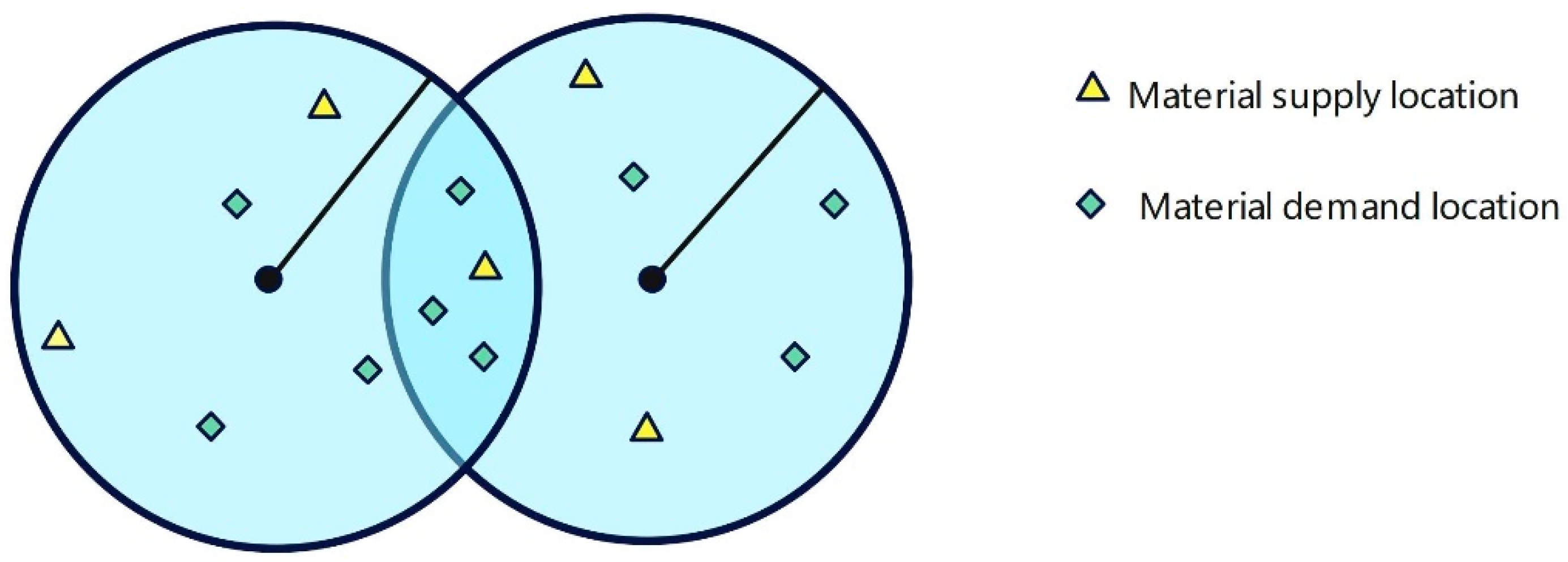
3.1. Problem Description

The layout of the construction site is assumed to be such that there are overlapping areas for two tower cranes, as shown in Figure 1. The lifting task allocation arrangements by mutual movement of known tower crane positions, supply point positions, and task point positions are optimized, and prioritization is then performed. For each tower crane, it is necessary to select supply points and task requirements within its operating range for effective lifting tasks. For multiple tower cranes, however, coordination of neighboring tower crane movements must also be considered to avoid the possibility of collisions in the overlap area. The lifting tasks within the overlap area of the two tower cranes need to be assigned to the appropriate tower crane to optimize the task lifting of the tower crane with minimum energy consumption and maximum utilization. This lifting task assignment optimization model achieves collision-free scheduling by prohibiting tower cranes from moving simultaneously within the overlap area.
This study provides various relevant engineering information. Specifically, all tower crane positions and supply and demand positions on the construction site are predetermined. The speed of multiple tower cranes is set according to specifications. Under this premise, four assumptions were implemented in the proposed optimization model to simplify the model, as shown in Table 1.
The model is constructed and optimized according to the conditions assumed above. Figure 2 depicts the main steps of the model to find the minimum energy consumption and maximum utilization. Firstly, the objective function of the optimization model is determined and expressed in an equation. Next, the task is rationally assigned to two tower cranes to form different lifting schemes. Then, analyze whether the lifting of the tasks passes through the overlapping area and only one tower crane is allowed to move in the overlapping area. Finally, the NSGA-III algorithm is applied for optimization and the Pareto front is calculated.

3.2. Objective Function

The objective function of the model is to minimize the energy cost of completing all task requests [34]. The energy cost includes the energy cost consumed by a tower crane with an unloaded hook moving from the demand point position to the supply point position, as well as the energy cost consumed by a tower crane with a fully loaded hook moving from the supply point position to the demand point position, as shown in Equation (1).
f 1 = M i n ( A 1 + A 2 )
In Equation (2), the binary variable  σ s , j , i , n = 1  indicates that the tower crane with an unloaded hook at position  n  moves from demand position  j  to supply position  i  in the lifting sequence  s α 1  represents the energy cost per unit time of the empty load lifting movement.  T i , j n  indicates the time of movement between two positions.  T l o a d i n g  indicates the time it takes for the empty hook to load the material at the supply position  i .
A 1 = s S i I n N ( T i , j n + T l o a d i n g ) · α 1 · σ s , j , i , n
Similarly, in Equation (3), the binary variable  δ s , i , j , n = 1  indicates that the tower crane with a fully loaded hook at position  n  moves from supply position  i  to demand position  j  in the lifting sequence  s α 2  represents the energy cost per unit time of a fully loaded lifting movement.  T u n l o a d i n g  represents the time it takes for the empty hook to unload the material at the required position  j .
A 2 = s S i I n N ( T i , j n + T u n l o a d i n g ) · α 2 · δ s , i , j , n
The objective function (4) is the energy consumption balance index of the machine [39], which is expressed as the standard deviation  A C  of the energy consumption of each tower crane, so that the task assigned by the tower crane and the energy consumption are fair [40]. This reflects the overall utilization rate and working efficiency of the machine, and ensures that the workload of each tower crane is balanced. There is a certain conflict between the two objective functions, the cost is reduced, and the utilization rate of the tower crane is also likely to increase. Therefore, these two objective functions are optimized to solve the optimal lifting task assignment scheme of prefabricated components on the construction site. Table 2 lists the notation used in the objective function section.
f 1 = M i n A C = m i n { max A c 1 ,   A c 2 ,   ,   A c m m i n { A c 1 ,   A c 2 ,   ,   A c m } }
The lifting task time of each tower crane is calculated as shown in Formula (5).
T m = T o , s i + T l o a d i n g + T s i , d j + T u n l o a d i n g ,         R = 1 T m = r = 1 R 1 ( T l o a d i n g + T s i 1 , d j 1 + T u n l o a d i n g + T ( d j 1 , s i ) ) + T l o a d i n g + T s i , d j + T u n l o a d i n g + T o , s i R 1

4. Multiple Tower Crane Task Schedule

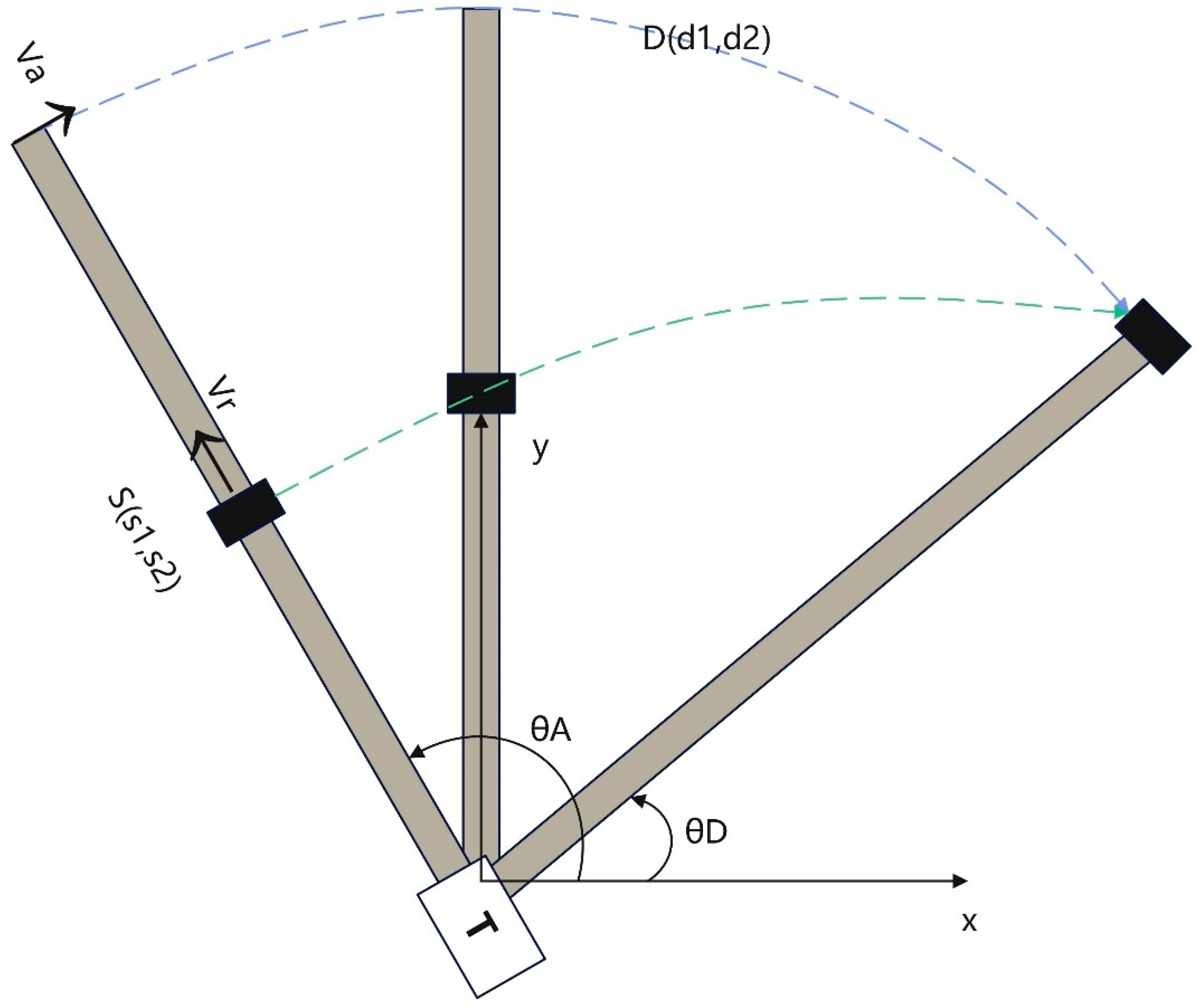
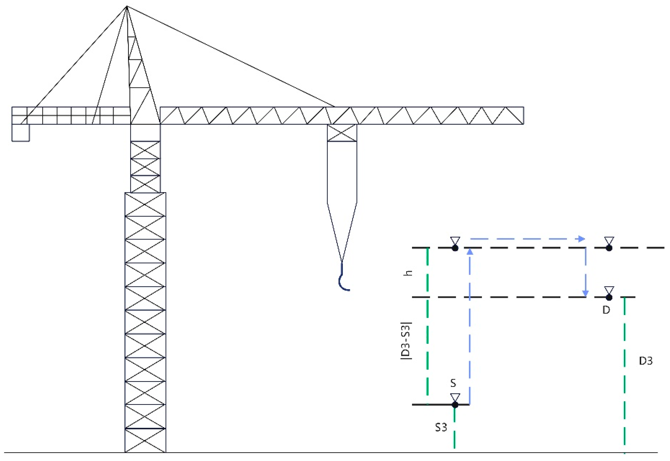
4.1. Estimate Tower Crane Movement Time between Two Locations

The hook travel time is the basis and key to solving the completion time of the lifting task of the multiple tower crane. According to the calculation model proposed by Zhang et al. [40], the calculation of the hook travel time of the tower crane is divided into horizontal travel time and vertical travel time. Establish a coordinate system according to the sitting position of the tower crane, set the position of the tower crane to  O m = ( o m 1 , o m 2 , o m 3 ) , set the coordinates of the supply point to  S i = ( s i 1 , s i 2 , s i 3 ) , and set the coordinates of the demand point to  D j = ( d j 1 , d j 2 , d j 3 ) , as shown in Figure 3. Table 3 summarizes the corresponding parameters of Formulas (6)–(10) and hook travel time.
The horizontal motion of the hook can be divided into the radial motion of the hook  T r ( i , j ) n  representation and the tangential motion of the hook  T a ( i , j ) n . Equation (6) represents the radial movement of the hook, and  V r  represents the radial movement speed. Equation (7) represents the tangential motion of the hook and  V a  represents the tangential movement speed.
T r ( i , j ) n = d j 1 2 + d j 2 2 s i 1 2 + s i 2 2 V r
T a ( i , j ) n = t a n 1 d j 2 d j 1 t a n 1 s i 2 s i 1 V a
The formulas are based on the comprehensive consideration of the tangential motion travel time and radial motion travel time of the hook. The introduction of coefficient  λ  represents the simultaneity of the operator’s operation of the hook in both radial and tangential directions. Therefore, the total travel time of the hook in the horizontal direction is shown in Formula (8). The value range of parameter  λ  is from zero to one, and the larger the parameter value, the higher the degree of simultaneous movement.
T h ( i , j ) n = max T r i , j n , T a i , j n + λ · min T r i , j n , T a i , j n
As shown in Figure 4, the travel time of the hook in the vertical direction is the minimum value  h  of the height difference between the supply and demand point positions plus twice the lifting height, and  V v  represents the moving speed of the hook in the vertical direction, as shown in Equation (9).
T v ( i , j ) n = d j 3 s i 3 + 2 · h V v
As shown in Equation (10), the total travel time of the hook is related to the coordinated movement of the hook in the horizontal and vertical directions, the complexity of the construction environment, and the construction site conditions. Use parameter  η  to indicate the operator’s level of operation in two directions of motion. The value range of the continuous parameter  η  is from 0 to 1. The smaller the parameter value, the higher the simultaneity of movement in both directions. The parameter  γ  indicates the difficulty level of operating the tower crane at position  n  due to different site conditions. The value of the parameter  γ  ranges from 0 to 1, and the smaller the parameter value, the higher the difficulty. Parameter  μ  is introduced as a construction environment parameter considering buildings built on-site or heavy materials that can lead to longer and more complex motion paths. The parameter  μ  represents the complexity of the travel route between supply location  i  and demand location  j  when the tower crane is set at position  n . The value of the parameter  μ  ranges from 0 to 1, and the smaller the parameter value, the lower the complexity of the construction environment.
T i , j n = μ · γ · max T h i , j n , T v i , j n + η · min T h i , j n , T v i , j n

4.2. The Constraints of the Proposed Optimization Model

Based on the model and scenario analyses, the constraints include two main aspects: the feasible combination of lifting tasks, and the prohibition of two towers being active in the overlapping area at the same time. Table 4 summarizes the relevant parameters of the model constraints.

4.2.1. Tower Crane Lifting Task Assignment Feasible Combination

The supply point of the material and the demand point of the task should be within the working range of the same tower crane. The binary variable  δ s , i , j = 1  is introduced to represent the transport of the material from the supply point  i  to the demand point  j  in the sequence  s , as shown in Formulas (11) and (12). A demand point can only be lifted by one tower crane. The binary variable  e r , s , n  is introduced. When  e r , s , n = 1 , it means that the tower crane at the position  n  requests the lifting task r in the sequence  s  type, as shown in Formula (13). Formula (14) indicates that lifting is feasible only when the supply and demand points are within the same working range of the tower crane.
δ s , i , j · ρ S i , T C n r 0 ,       i 1,2 , , I , j 1,2 , , J , s 1,2 , , S , n 1,2 , , N
δ s , i , j · ρ D j , T C n r 0 ,       i 1,2 , , I , j 1,2 , , J , s 1,2 , , S , n 1,2 , , N
r = 1 R e r , s , n = 1 ,       s 1,2 , , S , n 1,2 , , N
e r , s , n δ s , i , j ,       r 1,2 , , R , i 1,2 , , I , j 1,2 , , J , s 1,2 , , S , n 1,2 , , N

4.2.2. Eliminate the Service Schedules of Simultaneous Movement inside Overlapping Areas

Taking two tower cranes as examples, discuss and determine whether the tower cranes have entered or left the overlapping area. Table 5 summarizes the relevant parameters of Formulas (15)–(26) for calculating the overlapping region part.

Calculation of Overlapping Area Intersections

A plane coordinate system is established according to the positions of the two tower cranes. The values  O 1 ( x o 1 , y o 1 )  and  O 2 ( x o 2 , y o 2 )  represent the center coordinates of the tower crane, respectively. The working range is the arm length of the tower crane, and the arm length of the two tower cranes is  r 1  and  r 2 , respectively. The position of the two tower cranes is established on the x-axis for ease of calculation, as shown in Figure 5. According to the distance calculation Formula (15), the distance between the two towers is calculated as  O 1 O 2 .
O 1 O 2 = ( x o 1 + x 02 ) 2 + ( y o 1 + y 02 ) 2
According to Equations (12)–(16), the coordinate position of the intersection can be calculated.  β  can be calculated according to Equation (16).
β = arccos r 1 2 + O 1 O 2 2 r 2 2 2 · r 1 · O 1 O 2
Q 1 ( x q 1 , y q 1 )  and  Q 2 ( x q 2 , y q 2 )  are the coordinates of the intersection of two circles, and the specific values of the coordinates of the two nodes can be calculated according to the calculated  β , as shown in Equations (17)–(20).
x q 1 = r 1 · c o s β
y q 1 = r 1 · s i n β
x q 2 = r 1 · c o s β
y q 2 = r 1 · s i n β
For tower crane 1, the range of access to the overlapping region is  θ 1 1 , θ 2 1 , and the expressions for  θ 1 1  and  θ 2 1  are shown in Equations (21) and (22).
θ 1 1 = β
θ 2 1 = β
For the tower crane 2, the range of access to the overlapping area is  θ 1 2 , θ 2 2 , and the expressions for  θ 1 2  and  θ 2 2  are shown in Equations (23) and (24).
θ 1 2 = max a r c t a n 2 y q 1 y o 2 x q 1 x o 2 , a r c t a n 2 y q 2 y o 2 x q 2 x o 2
θ 2 2 = min a r c t a n 2 y q 1 y o 2 x q 1 x o 2 , a r c t a n 2 y q 2 y o 2 x q 2 x o 2

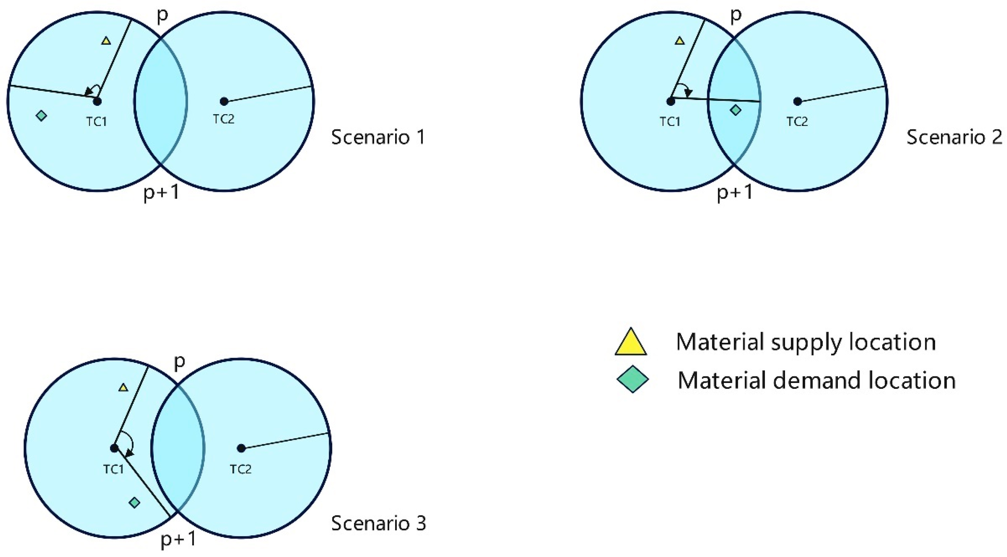
Identification of the Movement Routes Passing Overlapping Areas

Given the coordinate position of the supply and demand point, assuming that the supply point is not in the overlapping area, there are three situations, as follows:
(1)
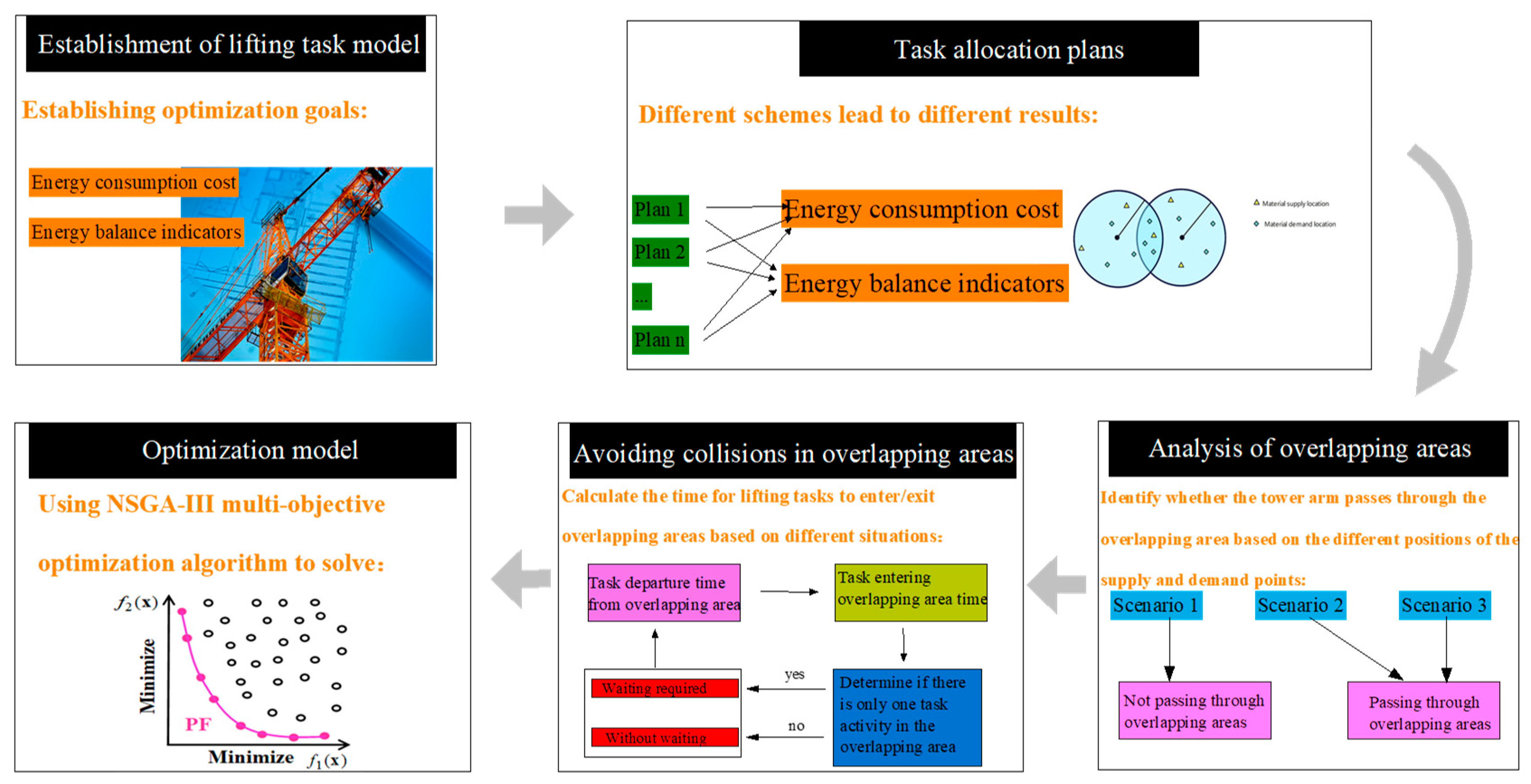
When the demand point is not in the overlapping area, and the tower crane does not pass through the overlapping area, there will be no space conflict between the tower cranes. So, the tower crane does not need to wait. The lifting time of the task is calculated as shown in Formula (25). Situation 1 in Figure 6 is shown;
T r n = T i , j n
(2)
When the demand point is not in the overlapping area, but the tower crane needs to pass through the overlapping area, space conflict may occur. During the lifting task, when the tower crane is about to enter the overlapping area, it is necessary to determine whether there is a tower crane performing the lifting task in the overlapping area. If there is a tower crane in the overlap area performing the lifting task, then the tower crane needs to wait for the previous tower crane to leave the overlap area. The lifting time of the task is calculated, as shown in Formula (26). If no other tower crane performs the task in the overlapping area, the lifting time of the task is calculated, as shown in Formula (25). Situation 2 in Figure 6 is shown as the following:
T r n = T i , j n + T r w a i t i n g
(3)
When the demand point is in the overlapping area, and the tower crane needs to pass through the overlapping area, space conflict may occur. Similar to scenario 2, it is necessary to determine whether there are other tower cranes performing lifting tasks in the overlapping area when entering the overlapping area. If it is determined that there are other tower cranes performing lifting tasks in the overlapping area, the lifting time of the task is calculated as shown in Formula (26). Otherwise, the Formula (25) is used to calculate. Scenario 3 in Figure 6 is shown.

Estimation of the Time for Each Action to Enter and Leave the Overlap Area

The  S n , s , q  variable is referenced as the start time of each action, and the unloaded lifting movement time before the first task starts is denoted as  B n . Therefore, in Formula (27), the start time of the full-load lifting movement for the first sequence is  s = 1 . For each no-load movement,  q = 2 , the start time is equal to the start time of the previous full-load lifting movement plus the moving time of the previous movement and the unloading time of the goods, as shown in Formula (28). The start time of each full-load lifting movement for a sequence  s > 1  is equal to the start time of the previous sequence of empty load lifting plus the time of the full-load lifting movement plus the time of loading the goods, as shown in Formula (29).
S n , s , q = B n + T l o a d i n g , s = 1 , q = 1 , n 1,2 , , N
S n , s , q = S n , s , q + 1 + i = 1 I j = 1 J δ s , i , j , n T i , j n + T u n l o a d i n g ,   q = 1 , s 1,2 , , S ,   n 1,2 , , N
S n , s , q = S n , s 1 , q 1 + i = 1 I j = 1 J σ s 1 , j , i , n T i , j n + T l o a d i n g ,   q = 2 , s 2,3 , , S   , n 1,2 , , N
As shown in Equation (30), the continuous variable  E n , s , q  is introduced as the time when the tower crane arrives at the intersection and enters the overlapping area. Define  E n , s , i , j  as the time from supply point  i  or demand point  j  to the selected intersection in the overlap area. As shown by Company (31), the continuous variable  G n , s , q  is introduced as the time when the tower crane arrives at the intersection and leaves the overlapping area.  G n , s , i , j  is defined as the moving time of the tower crane lifting task from entering the overlapping area to leaving the overlapping area.
E n , s , q = S n , s , q + i = 1 I j = 1 J E n , s , i , j , n 1,2 , , N , s 1,2 , , S , q 1,2
G n , s , q = E n , s , q + i = 1 I j = 1 J G n , s , i , j , n 1,2 , , N , s 1,2 , , S , q 1,2
When the demand point is not in the overlapping region  φ j = 0  and does not pass through the overlapping region  ω = 0 , the time to enter the overlapping region is shown in Formula (32) for each loaded and unloaded lifting motion. When the demand point is not in the overlapping region  φ j = 0  and does not pass through the overlapping region  ω = 0 , the time to leave the overlapping region is shown in Formula (33) for each loaded and unloaded lifting motion.
E n , s , q = 0 , n 1,2 , , N , s 1,2 , , S , q { 1,2 } , φ j = 0 , ω = 0
G n , s , q = 0 , n 1,2 , , N , s 1,2 , , S , q { 1,2 } , φ j = 0 , ω = 0
When the demand point is  φ j = 1  in the overlapping region and needs to pass through the overlapping region  ω = 1 , the time to enter the overlapping region is shown in Formulas (34) and (35) for each full-load lifting motion. When the demand point is  φ j = 1  in the overlapping region and needs to pass through the overlapping region  ω = 1 , the time to leave the overlapping region is shown in Formulas (36) and (37) for each empty-load lifting motion.
E n , s , i , j = i = 1 I j = 1 J δ s , i , j , n · ϑ s , i , j , n , p · N 1 , h i , p n + ϑ s , i , j , n , p + 1 · N 1 , h i , p + 1 n ,     n 1,2 , , N , s 1,2 , , S , φ j = 1 , ω = 1
E n , s , q = S n , s 1 , q + i = 1 I j = 1 J E n , s , i , j , n 1,2 , , N , s 1,2 , , S , q = 1 , φ j = 1 , ω = 1
G n , s , i , j = i = 1 I j = 1 J δ s , i , j , n · ϑ s , i , j , n , p · N 2 , h j , p n + ϑ s , i , j , n , p + 1 · N 2 , h j , p + 1 n + σ s , j , i , n · ϑ s , j , i , n , p · N 2 , h j , p n + ϑ s , j , i , n , p + 1 · N 2 , h j , p + 1 n + T u n l o a d i n g , n 1,2 , , P , s 1,2 , , S , q = 2 , φ j = 1 , ω = 1
G n , s , q = E n , s , q 1 + i = 1 I j = 1 J G n , s , i , j , n 1,2 , , N , s 1,2 , , S , q = 2 , φ j = 1 , ω = 1
When the demand point is not in the overlapping region  φ j = 0  and needs to pass through the overlapping region  ω = 1 , for each fully loaded lifting movement, the time to enter the overlapping region is shown in Formulas (34) and (35). For each fully loaded lifting movement, the time to leave this overlapping area is shown in Formulas (38) and (39). For each unloaded lifting movement, the time to enter the overlapping area is shown in Formulas (40) and (41). For each unloaded lifting movement, the time to leave the overlapping area is shown in Formulas (42) and (43).
G n , s , i , j = i = 1 I j = 1 J δ s , i , j , n · ϑ s , i , j , n , p · N 1 , h i , p n ϑ s , i , j , n , p + 1 · N 1 , h i , p + 1 n , n 1,2 , , N , s 1,2 , , S , φ j = 0 , ω = 1
G n , s , q = E n , s , q + i = 1 I j = 1 J G n , s , i , j , n 1,2 , , N , s 1,2 , , S , q = 1 , φ j = 0 , ω = 1
E n , s , i , j = σ s , j , i , n · ϑ s , j , i , n , p · N 2 , h j , p n + ϑ s , j , i , n , p + 1 · N 2 , h j , p + 1 n , n 1,2 , , N , s 1,2 , , S , φ j = 0 , ω = 1
E n , s , q = S n , s , q 1 + i = 1 I j = 1 J E n , s , i , j , n 1,2 , , N , s 1,2 , , S , q = 2 , φ j = 0 , ω = 1
G n , s , i , j = σ s , j , i , k · ϑ s , j , i , n , p · N 2 , h j , p n ϑ s , j , i , n , p + 1 · N 2 , h j , p + 1 n , n 1,2 , , N , s 1,2 , , S , φ j = 0 , ω = 1
G n , s , q = E n , s , q + i = 1 I j = 1 J G n , s , i , j , n 1,2 , , N , s 1,2 , , S , q = 2 , φ j = 0 , ω = 1
When the last task performed by the tower crane is located within the overlap area, then the time for that task to leave the overlap area is defined as infinite  M , as shown in Formula (44). The relevant parameters for calculating the entry and exit overlapping areas are shown in Table 6.
G n , s , q = M · i = 1 I j = 1 J δ s , i , j , n , n 1,2 , , N , s = S , q = 1 , φ j = 1 , ω = 1

4.2.3. Forbid Simultaneous Movements Inside Overlapping Areas

In order to avoid space conflicts during the lifting process and ensure safety, only one tower crane is allowed to move in the overlapping area during the execution of the lifting task. Therefore, the continuous variable  D n , s , q o . v , w  is introduced to represent the time difference between the motion  q  and  w  when two cranes at positions  n  and  o  in the work sequence  s  and  v  leave and enter the same overlapping area. The time difference  D n , s , q o . v , w  is calculated as shown in Equation (45). When the time difference between the two is non-negative, it means that the two tower cranes move simultaneously in the overlapping area.
D n , s , q o . v , w = G o , v , w E n , s , q , n , o 1,2 , , N , n o , s , v 1,2 , , S , q , w 1,2
In order to avoid the simultaneous movement of two tower cranes in the overlapping area, constraints (46) and (47) are used to ensure that the time differences of  D n , s , q o . v , w  and  D o , v , w n , s , q  are opposite signs. Then, we introduce bits of binary variables  χ n , s , q o . v , w : bits of  χ n , s , q o . v , w = 1  represents  D n , s , q o . v , w  positive, and bits of  χ n , s , q o . v , w = 0  represents  D n , s , q o . v , w  negative.  χ n , s , q o . v , w = 1  indicates that the time difference between two crane movements  q  and  w  is negative when the two cranes enter or leave the overlapping area at positions  n  and  o  in the work sequence  s  and  v χ n , s , q o . v , w = 0  means that the time difference between the two crane movements  q  and  w  is positive when the two cranes enter or leave the overlapping area at positions  n  and  o  in the working sequence  s  and  v . As stated in constraint (47), bits of  χ n , s , q o . v , w  and bits of  χ o , v , w n , s , q  cannot be equal to 1 at the same time, only one can be equal to 0 and 1.  ξ  indicates a positive number.
ξ · χ n , s , q o . v , w 1 D n , s , q o . v , w ξ · χ n , s , q o . v , w ,       n , o 1,2 , , N , n o , s , v 1,2 , , S , q , w 1,2
1 χ n , s , q o . v , w χ o , v , w n , s , q 0 ,       n , o 1,2 , , N , n o , s , v 1,2 , , S , q , w 1,2
To avoid two tower cranes moving in the overlap area at the same time, one of the tower cranes needs to wait in the safe area until the tower crane leaves the overlap area. The waiting time is calculated, as shown in Formula (48).
T r w a i t i n g = min D n , s , q o . v , w , D o , v , w n , s , q 0 ,       n , o 1,2 , , N , n o , s , v 1,2 , , S , q , w 1,2

5. Experiment Results and Discussion

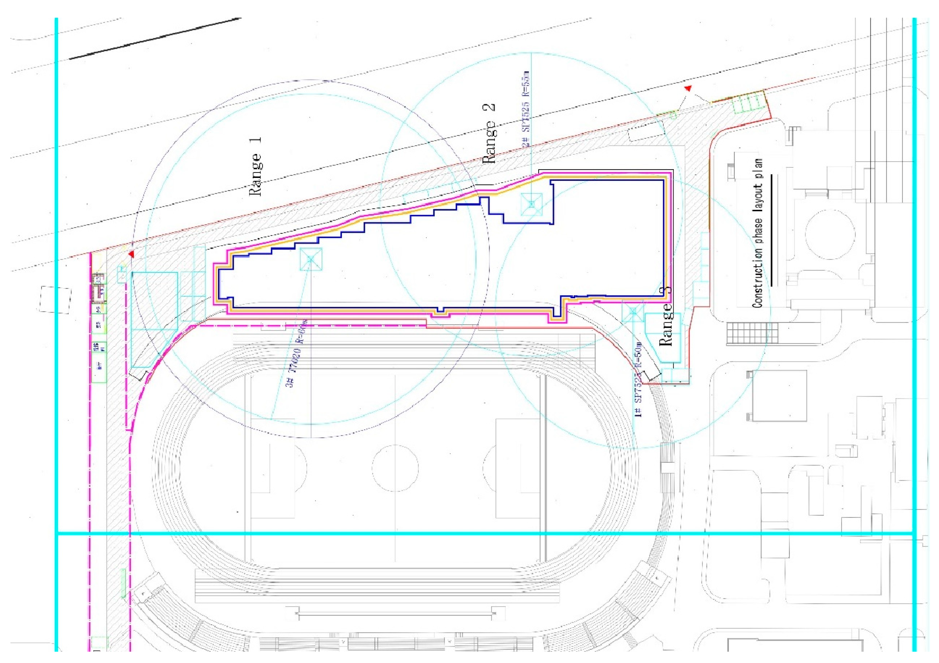
5.1. Case Background

This case study focuses on the construction project of green construction, in a production–education integration training building in a certain school of Jinan. The project is a 16-story assembly construction project with assembled components, mainly using prefabricated structural columns, prefabricated structural beams, and prefabricated structural panels. And the assembly rate is greater than 50%. In Figure 7, as an example, tower crane 1 and tower crane 2 worked together to lift sixteen precast columns on the first floor of this project. And there are two supply points to supply materials to the two tower cranes, respectively. A coordinate system is established with the horizontal and vertical coordinates of tower crane 1 as the origin and the coordinates of tower crane 2 are located on the positive semi-axis of the x-axis. These two tower cranes have overlapping areas for lifting, and their operations are not constrained. We aim to optimize the schedule of lifting tasks between two tower cranes and obtain the optimal lifting plan.

5.2. Input Model Parameter

Table 7, Table 8 and Table 9 show the position coordinates of the feed, the position coordinates of the feed, and the position coordinates of the two tower cranes. The vertical speed is set to  V v = 136  m/min. The radial speed is set to  V r = 60  m/min. The rotary angular speed is set to  V a = 0.5  arc/min, and the lifting capacity of the tower crane is 30. The maximum working range of the two tower cranes is 60 m and 55 m, respectively. Under good weather conditions and normal construction operations, the travel path of the hook between the supply and demand positions is unobstructed and there is no additional delay. The parameter  μ  is set to one. To assess the ability of the tower crane operator in the field, parameters  γ λ  and  β  are set to 1.0, 1.0, and 0.25, respectively. The material handling time is set to 1.0-time unit (minutes). Unit cost parameters  Ω ¯  and  Ω ̿  are set to 3 CNY/min and 6 CNY/min, respectively.
We applied Python software to solve the above problems. The running environment is a 36-core CPU with 72 threads, and the memory is 128 g. The parameters, such as population size, crossover probability, and mutation probability, are constant. Each demand point requires prefabricated component materials, and the supply point can provide the required materials to the demand point.

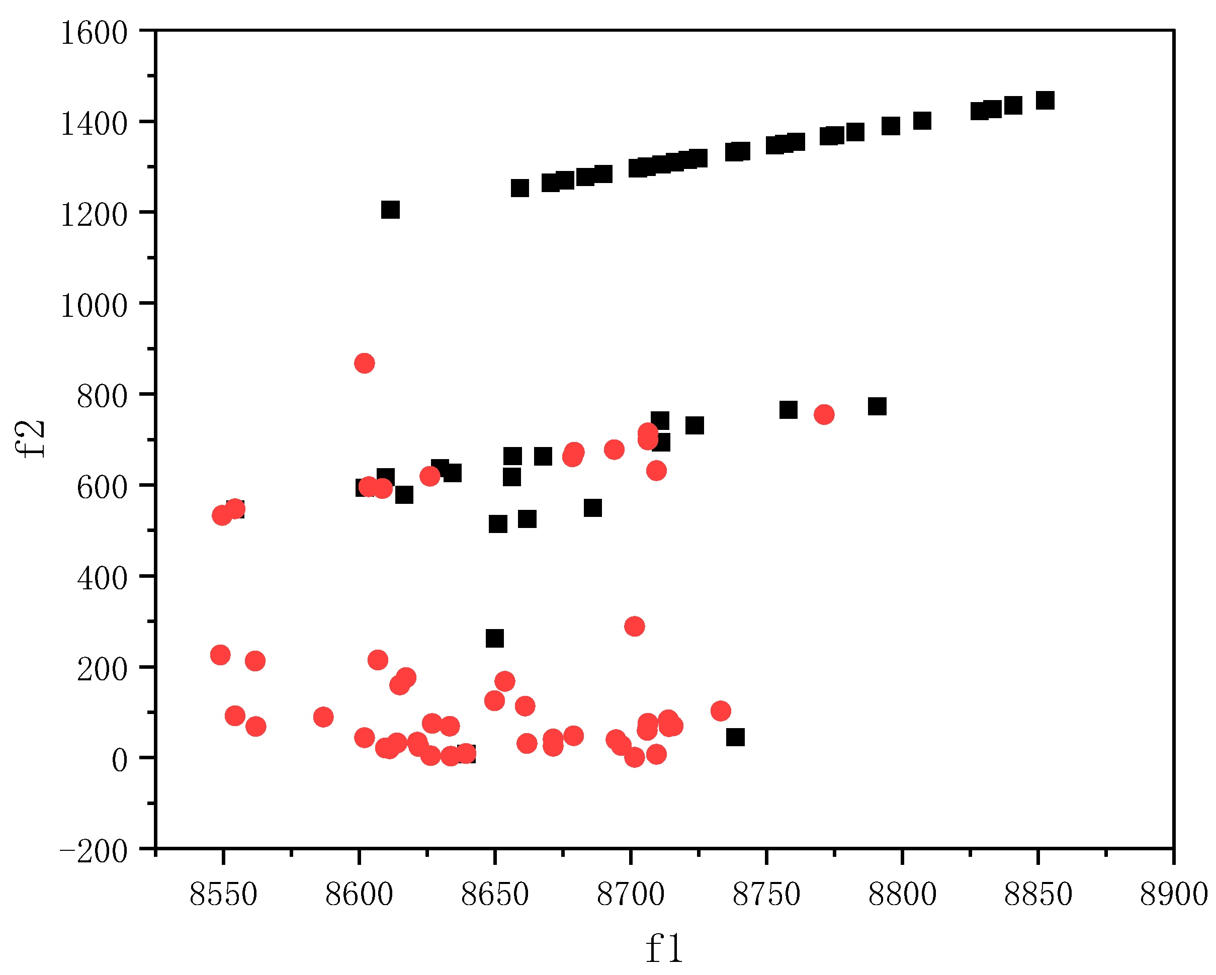
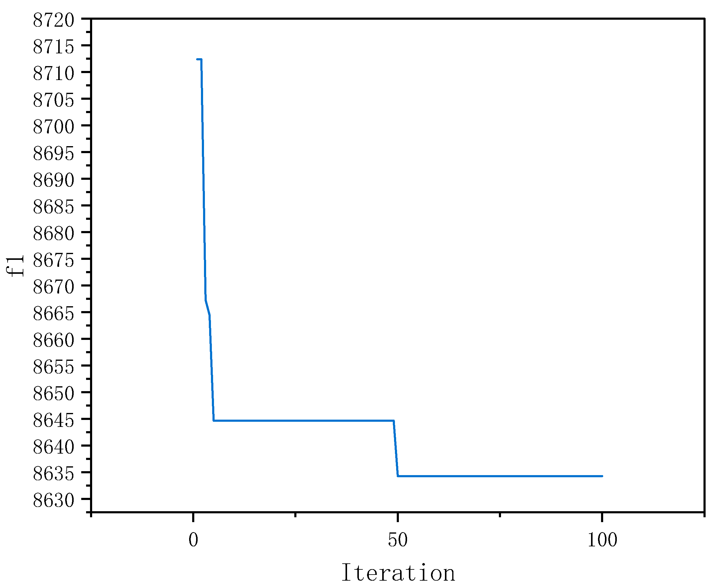
5.3. Multi-Objective Optimized Results

This article aims to minimize energy consumption costs while ensuring that there are no conflicts, while ensuring a relatively balanced workload for each tower crane and improving the resource utilization of prefabricated component hoisting on the construction site. We aim to improve the lifting efficiency, safety, and cost of prefabricated components on construction sites. Each point at the Pareto front calculated using the NSGA-III algorithm represents an almost optimal solution and can be used as a candidate solution for decision-making. From the results, it can be seen that the non-dominated solutions calculated by the NSGA-III multi-objective optimization algorithm have a certain practical significance.
Set the population size for each generation to 60. To display the Pareto front more intuitively, take the objective function  f 1  as the horizontal axis and the objective function  f 2  as the vertical axis. Utilizing the NSGA-III multi-objective optimization algorithm to solve two conflicting objective functions allows us to obtain a Pareto front solution that closely approximates the optimal solution. This approach effectively offers an optimal trade-off between the two optimization objectives. The NSGA-III algorithm effectively manages to navigate the search space and identify solutions that excel in both objectives, thus providing a comprehensive and balanced perspective. From Figure 8, The red circle represents the objective function value of the 100th generation population, the black circle represents the objective function value of the first generation population. It can be seen that for the objective function  f 1 , the difference between the maximum energy cost consumption and the minimum energy cost consumption is approximately 300. For the objective function  f 2 , the difference between the maximum mechanical energy consumption balance difference and the minimum mechanical energy consumption difference is approximately 1500. This indicates that achieving the optimal solution for the two objective functions requires careful consideration of the trade-offs involved. The initial objective function  f 1  is mainly distributed between 8550 and 8850, while objective function  f 2  is distributed between 0 and 1500. As the number of iterations increases, the Pareto front solution moves towards the lower left corner, the objective function  f 1  gradually approaches 8523, and objective function  f 2  gradually approaches 0. It can be noticed that the range of variation in  f 2  is more pronounced. The optimized Pareto front is located in the lower left corner, indicating that the obtainable solutions are non-dominated. The results are consistent with the definition of the non-dominated solution set, indicating that the obtained optimal solutions are reliable. The study shows that multi-objective tower crane task scheduling optimization based on a non-dominated genetic algorithm is reasonable and effective. Therefore, decision-makers can explore the results while satisfying constraints to find the optimal solutions that have the best balance between the objective functions. When the optimal solution set is obtained, decision-makers can use different comprehensive evaluation methods to compare and select plans.
In order to further verify the rationality and effectiveness of the proposed multi-objective model and algorithm, the average convergence trends of the two objective function values will be plotted separately.
In order to check whether it is a reasonable and effective Pareto optimal solution, optimization is carried out by using the NSGA-III multi-objective optimization algorithm, and the corresponding objective function values are obtained. The relevant parameters are consistent with the previous design. First, the average objective function value of 100 generations is calculated as the vertical coordinate of each generation using the optimization algorithm. Figure 9 shows the average change of the objective function hair f1 over the 100 iterations of the calculation. It can be seen that as the NSGA-III multi-objective optimization algorithm continues to search, the average objective function value gradually decreases and eventually stabilizes, indicating that the algorithm is gradually approaching the optimal solution and showing that the algorithm is effective. After 100 iterations, the average objective function value of f2 also stabilizes, and the convergence trend is shown in Figure 10. Combining the above results and analysis, the results obtained in this article based on the NSGA-III multi-objective optimization algorithm optimization are reasonable.
In this article, the comprehensive evaluation TOPSIS [41] is selected to rank the plans. The weight distribution is different for different objectives. This article focuses more on energy consumption cost, so the weight value is assigned as 0.6, while the other objective weight value is assigned as 0.4. Based on the Pareto front obtained through optimization using the NSGA-III multi-objective optimization algorithm, the TOPSIS comprehensive evaluation method is used for calculation. The positive ideal solution distance, negative ideal solution distance, and relative closeness values of each plan are calculated. Finally, the plans are ranked based on the relative closeness values. The ranking of the plans is shown in Table 10.
As can be seen from Table 10, there are some commonalities among the top 11 solutions. For example, each solution has seven tasks for tower crane 1 and nine tasks for tower crane 2. The first six tasks and the sequence of tasks lifted by tower crane 1 are the same in each scenario. It can also be noticed that most of the tasks in the overlap area are lifted by tower crane 2. So, for tower crane 2, the main preference is more on the condition of balancing the utilization of mechanical equipment for the assignment of tasks. The different weight values assigned will lead to a different selection of solutions. To avoid conflicts between the two tower cranes, reasonable scheduling of lifting tasks and optimization of lifting sequences can effectively improve efficiency, thereby saving energy consumption costs. At the same time, it ensures a relatively balanced energy consumption and utilization rate for each tower crane.

5.4. Discussion

When the weights of the objective function changed, what happened to the choice of the program? The relationship between objectives and weights is represented by Equation (49), which was discussed as follows:
f = a · f 1 + b · f 2
In the formula,  a  and  b  represent the weight values of different objective functions.
When the weight of objective function  f 1  is between 0.01 and 0.19, the top two ranked schemes are scheme 1 and scheme 11, respectively; when the weight of objective function  f 1  is in the range of [0.2, 0.72], the top two ranked solutions are scheme 11 and scheme 1, respectively; it can be observed that when the weight values are between 0.01 and 0.72, the top two are both scheme 1 and scheme 11. When the decision-maker prefers the objective function  f 2  to be smaller, then scheme 11 may become the final scheduling solution.
When the weight of objective function  f 1  is in the range of [0.73, 0.82], the top two ranked schemes are scheme 2 and scheme 11, respectively; when the weight of the objective function  f 1  is between 0.83 and 0.99, the top two schemes are scheme 2 and scheme 9, respectively. The weight value of objective function  f 1  gradually increases, and the first-ranked scheme has changed from scheme 1 to scheme 2. But the objective function  f 2  of scheme 2 is better than scheme 1. Scheme 9 may have been the ultimate scheduling option when decision-makers wanted lower energy costs. However, scheme 9 was not the top choice. The decision-makers preferred to have lower energy costs in real situations. The value of objective function  f 1  for scheme 9 was also within an acceptable range, so scheme 9 was more likely to be selected in practice.
From this, it can be seen that the higher the weight value of the objective function, the optimal objective function value will be selected for the final solution. Different comprehensive evaluation methods and emphasis on different goals will lead to differences in the scheduling plan. The weighted approach to screening results reflects the role of differences between targets on screening results. At the same time, the weights and decision-makers together influence the final scheduling result.

6. Conclusions

This study aims to improve the efficiency of prefabricated component lifting by minimizing energy consumption costs and reducing the energy consumption of mechanical equipment. Various binary variables and linear control constraints are introduced to simulate tower crane operations and avoid the simultaneous movement of tower arms in overlapping areas. Under the premise of ensuring that no conflicts occur, a multi-objective optimization model for the schedule of prefabricated component lifting tasks on the construction site is established. The NSGA-III multi-objective optimization algorithm is used to solve the mathematical model, and the following conclusions are drawn:
As the number of iterations increases, the Pareto front solution obtained approaches the optimal solution.
The optimal solution is a set of solutions, each of which is a non-dominated solution. These solutions represent trade-offs between different objectives. The decision-maker can sort the solutions in the solution set according to the actual situation.
The top 11 candidates using the comprehensive TOPSIS evaluation methodology have the same number of tasks assigned to tower crane 1 and have close to the same lifting tasks and prioritization. The task schedule for tower crane 2 is shown to balance the energy consumption costs of the two tower cranes.
The NSGA-III optimization in this study achieved good results. To a certain extent, it improved the efficiency of prefabricated component lifting on the construction site, saved costs, and optimized the utilization of resources. This study has a certain scientific significance and feasibility.
Different ranges of weights are discussed that will have an impact on the ranking of the schemes and may affect the final scheduling results.
This article has made some efforts for the task scheduling problems of overlapping multiple tower cranes. However, there are still some limitations. For example, in the simulation process, the choice of multiple supply points is not provided; the situation that the supply points are located in the part of the overlapping area is not discussed; and the prioritized sequence of lifting between different components is not taken into account. It is hoped that more in-depth research can be carried out in the future, and that the intelligent research can be better combined with the dynamic lifting of prefabricated components on the construction site, so as to better optimize the process of lifting, and to improve the safety, efficiency, and resource utilization of lifting.

Author Contributions

Y.W., W.Z. and W.C. conceived and planned the review. Y.W. provided data. W.Z. performed the search and analyzed the data, and wrote the article. Y.W. and W.C. revised the article critically. Y.W. and G.Z. provided fund support. All authors have read and agreed to the published version of the manuscript.

Funding

Major Scientific and Technological Innovation Projects of Key R & D Plan of Shandong Province [grant numbers 2021CXGC011204], Postgraduate Education Quality Improvement Plan Project “Engineering Valuation and Investment Control Course Case Library” of Shandong Province [grant numbers SDYAL21157].

Institutional Review Board Statement

Not applicable.

Informed Consent Statement

Not applicable.

Data Availability Statement

The data presented in this study are available on request from the corresponding author. The data are not publicly available due to privacy.

Conflicts of Interest

The authors declare no conflict of interest.

Nomenclature

NSGA-IIINon-dominated sorting genetic algorithm-III
TOPSISTechnique for order preference by similarity to an ideal solution
MILPMixed integer linear problem
USCAUpgraded sine cosine algorithm
PSOParticle swarm optimization
TCLPTower crane layout planning
BIMBuilding information modeling
GISGeographic information system
RRTRapidly exploring random tree
NSGA-IINon-dominated sorting genetic algorithm-II
TOPSISTechnique for order preference by similarity to an ideal solution
MTSPMultiple traveling salesman problem
FIFSFirst-in-first-serve
SJFShortest job first
NNFNearest neighbor first
CCGACooperative coevolutionary genetic algorithm
VEGAVector-evaluated genetic algorithm
MOGAMultiple objective genetic algorithm
SPEAStrength Pareto evolutionary algorithm
3D-CESThree-dimensional crane evaluation system

References

  1. Yang, Y.H.; Liu, Y.S. Research on the Application of Prefabricated Buildings in Affordable Housing Construction in China. In Proceedings of the 6th International Symposium on Project Management (ISPM), Chongqing University Posts & Telecommunication, Chongqing, China, 21–23 July 2018; Aussino Academic Publishing House: Marrickville, NSW, Australia, 2018. [Google Scholar]
  2. Yin, J.; Li, J.; Fang, Y.; Yang, A. Service scheduling optimization for multiple tower cranes considering the interval time of the cross-tasks. Math. Biosci. Eng. 2023, 20, 5993–6015. [Google Scholar] [CrossRef]
  3. Daoud, A.O.; El Hefnawy, M.; Wefki, H. Investigation of critical factors affecting cost overruns and delays in Egyptian mega construction projects. Alex. Eng. J. 2023, 83, 326–334. [Google Scholar] [CrossRef]
  4. Lin, X.; Han, Y.; Guo, H.; Luo, Z.; Guo, Z. Lift path planning for tower cranes based on environmental point clouds. Autom. Constr. 2023, 155, 105046. [Google Scholar] [CrossRef]
  5. Huang, C.; Li, W.; Lu, W.; Xue, F.; Liu, M.; Liu, Z. Optimization of multiple-crane service schedules in overlapping areas through consideration of transportation efficiency and operational safety. Autom. Constr. 2021, 127, 18. [Google Scholar] [CrossRef]
  6. Huang, C.; Wang, Z.K.; Li, B.; Wang, C.; Xu, L.S.; Jiang, K.; Liu, M.; Guo, C.X.; Zhao, X.F.; Yang, H. Discretized Cell Modeling for Optimal Layout of Multiple Tower Cranes. J. Constr. Eng. Manag. 2023, 149, 19. [Google Scholar] [CrossRef]
  7. Jiang, H.; Miao, Y.B. Construction Site Layout Planning Using Multiple-Level Simulated Annealing. In Proceedings of the Computing Conference, Virtual, 15–16 July 2021; Springer International Publishing: Cham, Switzerland, 2021. [Google Scholar]
  8. Kaveh, A.; Vazirinia, Y. An Upgraded Sine Cosine Algorithm for Tower Crane Selection and Layout Problem. Period. Polytech.-Civ. Eng. 2020, 64, 325–343. [Google Scholar] [CrossRef]
  9. Khodabandelu, A.; Park, J.; Arteaga, C. Improving Multitower Crane Layout Planning by Leveraging Operational Flexibility Related to Motion Paths. J. Manag. Eng. 2023, 39, 17. [Google Scholar] [CrossRef]
  10. Li, R.; Chi, H.L.; Peng, Z.; Li, X.; Chan, A.P. Automatic tower crane layout planning system for high-rise building construction using generative adversarial network. Adv. Eng. Inform. 2023, 58, 19. [Google Scholar] [CrossRef]
  11. Liu, C.; Zhang, F.; Han, X.; Ye, H.; Shi, Z.; Zhang, J.; Wang, T.; She, J.; Zhang, T. Intelligent Optimization of Tower Crane Location and Layout Based on Firefly Algorithm. Comput. Intell. Neurosci. 2022, 2022, 13. [Google Scholar] [CrossRef]
  12. Lu, Y.; Zhu, Y.Q. Integrating Hoisting Efficiency into Construction Site Layout Plan Model for Prefabricated Construction. J. Constr. Eng. Manag. 2021, 147, 15. [Google Scholar] [CrossRef]
  13. Riga, K.; Jahr, K.; Thielen, C.; Borrmann, A. Mixed integer programming for dynamic tower crane and storage area optimization on construction sites. Autom. Constr. 2020, 120, 15. [Google Scholar] [CrossRef]
  14. Younes, A.; Marzouk, M. Tower cranes layout planning using agent-based simulation considering activity conflicts. Autom. Constr. 2018, 93, 348–360. [Google Scholar] [CrossRef]
  15. Zhang, Z.Q.; Pan, W.; Pan, M. Critical considerations on tower crane layout planning for high-rise modular integrated construction. Eng. Constr. Archit. Manag. 2022, 29, 2615–2634. [Google Scholar] [CrossRef]
  16. Wu, K.Y.; De Soto, B.G. Lifting Sequence Optimization of Luffing Tower Cranes Considering Motion Paths with Dynamic Programming. J. Constr. Eng. Manag. 2021, 147, 16. [Google Scholar] [CrossRef]
  17. Burkhardt, M.; Gienger, A.; Sawodny, O. Optimization-Based Multipoint Trajectory Planning Along Straight Lines for Tower Cranes. IEEE Trans. Control Syst. Technol. 2023, 8, 290–297. [Google Scholar] [CrossRef]
  18. Dutta, S.; Cai, Y.; Huang, L.; Zheng, J. Automatic re-planning of lifting paths for robotized tower cranes in dynamic BIM environments. Autom. Constr. 2020, 110, 19. [Google Scholar] [CrossRef]
  19. Li, X.; Chi, H.L.; Wu, P.; Shen, G.Q. Smart work packaging-enabled constraint-free path re-planning for tower crane in prefabricated products assembly process. Adv. Eng. Inform. 2020, 43, 16. [Google Scholar] [CrossRef]
  20. Lin, Z.Y.; Petzold, F.; Hsieh, S.H. Automatic Tower Crane Lifting Path Planning Based on 4D Building Information Modeling. In Proceedings of the Construction Research Congress (CRC) on Construction Research and Innovation to Transform Society, Del E Webb Sch Construct, Arizona State University, Tempe, AZ, USA, 8–10 March 2020; American Society of Civil Engineers: New York, NY, USA, 2020. [Google Scholar]
  21. Ji, Y.S.; Leite, F. Optimized Planning Approach for Multiple Tower Cranes and Material Supply Points Using Mixed-Integer Programming. J. Constr. Eng. Manag. 2020, 146, 11. [Google Scholar] [CrossRef]
  22. Zhou, C.; Dai, F.; Xiao, Z.; Liu, W. Location Optimization of Tower Cranes on High-Rise Modular Housing Projects. Buildings 2023, 13, 115. [Google Scholar] [CrossRef]
  23. Wu, K.Y.; De Soto, B.G.; Zhang, F.L. Spatio-temporal planning for tower cranes in construction projects with simulated annealing. Autom. Constr. 2020, 111, 17. [Google Scholar] [CrossRef]
  24. Zhang, W.; Zhang, H.; Yu, L. Collaborative Planning for Stacking and Installation of Prefabricated Building Components Regarding Crane-Collision Avoidance. J. Constr. Eng. Manag. 2023, 149, 04023029. [Google Scholar] [CrossRef]
  25. Khodabandelu, A.; Park, J.; Arteaga, C. Crane operation planning in overlapping areas through dynamic supply selection. Autom. Constr. 2020, 117, 14. [Google Scholar] [CrossRef]
  26. Zhou, Y.; Zhang, E.; Guo, H.; Fang, Y.; Li, H. Lifting path planning of mobile cranes based on an improved RRT algorithm. Adv. Eng. Inform. 2021, 50, 9. [Google Scholar] [CrossRef]
  27. Zhu, A.M.; Zhang, Z.Q.; Pan, W. Crane-lift path planning for high-rise modular integrated construction through metaheuristic optimization and virtual prototyping. Autom. Constr. 2022, 141, 21. [Google Scholar] [CrossRef]
  28. Guo, H.; Zhou, Y.; Pan, Z.; Zhang, Z.; Yu, Y.; Li, Y. Automated Selection and Localization of Mobile Cranes in Construction Planning. Buildings 2022, 12, 580. [Google Scholar] [CrossRef]
  29. Wang, J.; Zhang, Q.; Yang, B.; Zhang, B. Vision-Based Automated Recognition and 3D Localization Framework for Tower Cranes Using Far-Field Cameras. Sensors 2023, 23, 851. [Google Scholar] [CrossRef]
  30. Huang, L.; Pradhan, R.; Dutta, S.; Cai, Y. BIM4D-based scheduling for assembling and lifting in precast-enabled construction. Autom. Constr. 2022, 133, 14. [Google Scholar] [CrossRef]
  31. Tarhini, H.; Maddah, B.; Hamzeh, F. The traveling salesman puts-on a hard hat—Tower crane scheduling in construction projects. Eur. J. Oper. Res. 2021, 292, 327–338. [Google Scholar] [CrossRef]
  32. Hammad, A.W.; Rey, D.; Akbarnezhad, A.; Haddad, A. Integrated mathematical optimisation approach for the tower crane hook routing problem to satisfy material demand requests on-site. Adv. Eng. Inform. 2023, 55, 13. [Google Scholar] [CrossRef]
  33. Motyčka, V.; Gašparík, J.; Přibyl, O.; Štěrba, M.; Hořínková, D.; Kantová, R. Effective Use of Tower Cranes over Time in the Selected Construction Process. Buildings 2022, 12, 436. [Google Scholar] [CrossRef]
  34. Yin, J.; Li, J.; Yang, A.; Cai, S. Optimization of service scheduling problem for overlapping tower cranes with cooperative coevolutionary genetic algorithm. Eng. Constr. Archit. Manag. 2024, 31, 1348–1369. [Google Scholar] [CrossRef]
  35. Mousaei, A.; Taghaddos, H.; Marzieh Bagheri, S.; Hermann, U. Optimizing Heavy Lift Plans for Industrial Construction Sites Using Dijkstra’s Algorithm. J. Constr. Eng. Manag. 2021, 147, 16. [Google Scholar] [CrossRef]
  36. Han, S.; Bouferguene, A.; Al-Hussein, M.; Hermann, U. 3D-Based Crane Evaluation System for Mobile Crane Operation Selection on Modular-Based Heavy Construction Sites. J. Constr. Eng. Manag. 2017, 143, 12. [Google Scholar] [CrossRef]
  37. Wu, K.; García, D.E.; Soto, B. Spatiotemporal Modeling of Lifting Task Scheduling for Tower Cranes with a Tabu Search and 4-D Simulation. Front. Built Environ. 2020, 6, 79. [Google Scholar] [CrossRef]
  38. Gopu, A.; Thirugnanasambandam, K.; AlGhamdi, A.S.; Alshamrani, S.S.; Maharajan, K.; Rashid, M. Energy-efficient virtual machine placement in distributed cloud using NSGA-III algorithm. J. Cloud Comput.-Adv. Syst. Appl. 2023, 12, 20. [Google Scholar] [CrossRef]
  39. Saeedvand, S.; Aghdasi, H.S.; Baltes, J. Robust multi-objective multi-humanoid robots task allocation based on novel hybrid metaheuristic algorithm. Appl. Intell. 2019, 49, 4097–4127. [Google Scholar] [CrossRef]
  40. Zhang, Z.Q.; Ma, S.L.; Jiang, X.Y. Research on Multi-Objective Multi-Robot Task Allocation by Lin-Kernighan-Helsgaun Guided Evolutionary Algorithms. Mathematics 2022, 10, 4714. [Google Scholar] [CrossRef]
  41. Li, K.; Duan, T.; Li, Z.; Xiahou, X.; Zeng, N.; Li, Q. Development Path of Construction Industry Internet Platform: An AHP—TOPSIS Integrated Approach. Buildings 2022, 12, 441. [Google Scholar] [CrossRef]
Figure 1. Two tower cranes with overlapping areas.
Buildings 14 00867 g001
Figure 2. Optimization model framework for task schedule of prefabricated component lifting on construction sites.
Buildings 14 00867 g002
Figure 3. Coordinate system of tower crane’s horizontal motion.
Buildings 14 00867 g003
Figure 4. Coordinate system of tower crane’s vertical motion.
Buildings 14 00867 g004
Figure 5. Diagram of tower position.
Buildings 14 00867 g005
Figure 6. Analysis of whether the tower arm passes through the overlapping area.
Buildings 14 00867 g006
Figure 7. Project diagram.
Buildings 14 00867 g007
Figure 8. Reflection of the calculated values of the two objective functions.
Buildings 14 00867 g008
Figure 9. f 1  Optimization convergence curve.
Buildings 14 00867 g009
Figure 10. f 2  Optimization convergence curve.
Buildings 14 00867 g010
Table 1. Model assumptions.
AssumptionsProblem Description
Assumption 1Every time the tower crane moves, it selects the shortest path along a small arc between two positions;
Assumption 2Each tower crane is only allowed to lift one type of material at a time;
Assumption 3There is no priority limit between request tasks;
Assumption 4The default initial position of each tower crane for each task is the supply point position for the current task.
Table 2. Parameters and variables in the objective function section.
SymbolTypeExpression
  A 1 Continuous variableThe total energy cost from material demand locations to material supply locations;
  A 2 Continuous variableThe total energy cost from material supply locations to material demand locations;
  σ s , j , i , n Binary variable σ s , j , i , n  = 1 indicates a tower crane at a location  n  travels from a demand location  j  to a supply location  i  in a work sequence  s ;
  δ s , i , j , n Binary variable δ s , i , j , n  = 1 indicates a tower crane at a location  n  transports material from a supply location  i  to a demand location  j  in a work sequence  s ;
  T l o a d i n g Continuous parameterThe time to load materials from a material supply location;
  T u n l o a d i n g Continuous parameterThe time to unload materials to a material demand location;
  α 1 Continuous parameterThe estimated unit energy cost of empty loaded lifting movement in a minute;
  α 2 Continuous parameterThe estimated unit energy cost of fully loaded lifting movement in a minute;
  T i , j n Continuous parameterThe hook travel time of a tower crane at location  n  between a supply location  i  and a demand location  j ;
  T m Continuous parameterThe time required for tower crane  m  to complete the lifting task;
  T o , s i Continuous parameterThe movement time of the hook from the initial position to the supply location;
  R Continuous parameterNumber of tasks.
Table 3. Travel time calculation-related symbols.
SymbolExpression
  i Material supply location  i ;
  j Material demand location  j ;
  o m 1 , o m 2 , o m 3 The tower crane location;
  s i 1 , s i 2 , s i 3 Coordinates of the supply location;
  d j 1 , d j 2 , d j 3 Coordinates of the demand location;
  T r ( i , j ) n Radial travel time of the hook from  i  to  j ;
  T a ( i , j ) n Tangential travel time of the hook from  i  to  j ;
  T h ( i , j ) n The horizontal movement time of the hook from  i  to  j ;
  T v ( i , j ) n The vertical movement time of the hook from  i  to  j ;
  V r The speed at which the hook moves in the radial direction;
  V a The speed at which the hook moves in the tangential direction;
  V v The speed at which the hook moves in the vertical direction;
  λ The degree of simultaneous radial and tangential movement of the hook;
  h The minimum value of the lifting height;
  μ Complexity level of construction environment;
  γ The level of difficulty of tower crane operation;
  η The horizontal movement of the hook in both the horizontal and vertical directions.
Table 4. Parameters related to constraints.
SymbolTypeExpression
  e r , s , n Binary parameter e r , s , n = 1 ,  indicates that the tower crane at  n  requests the lifting task  r  in sequence  s ;
  χ n , s , q o , v , w Binary parameter χ n , s , q o , v , w = 1 ,  indicates that in the work sequence  s  and  v , when two tower cranes enter or leave the overlapping area at positions  n  and  o , the time difference between two tower crane movements  q  and  w  cannot be negative;
  D n , s , q o . v , w Continuous parameterRepresents the time difference between the motion  q  and  w  when two tower cranes at positions  n  and  o  in the work sequence  s  and  v  leave and enter the overlapping area.
Table 5. The relevant parameters of the overlapping region calculation formula.
SymbolExpression
  O 1 O 2 The distance between the two tower cranes;
  O 1 ( x o 1 , y o 1 ) Tower 1 coordinates;
  O 2 ( x o 2 , y o 2 ) Tower 2 coordinates;
Q 1 ( x q 1 , y q 1 ) Q 2 ( x q 2 , y q 2 ) The coordinate position of the two intersection points where the working range of the two tower cranes overlaps;
  r 1 Tower 1 forearm length;
  r 2 Tower 2 forearm length;
  β The angle of the intersection with respect to the tower crane at the origin;
  [ θ 1 , θ 2 ] The range of overlapping areas;
  T r w a i t i n g The time that a tower crane needs to wait in order to avoid conflict.
Table 6. The relevant parameters for entering and leaving overlapping areas were calculated.
SymbolTypeExpression
  B n Continuous parameterThe time when the tower crane starts the first lifting task;
  S n , s , q Continuous parameterThe start time of each action of the tower crane lifting task;
  E n , s , q Continuous parameterThe time when the tower crane enters the overlap area;
  E n , s , i , j Continuous parameterThe movement time of the tower crane into the overlapping area from supply point  i  or demand point  j  to the selected intersection;
  G n , s , q Continuous parameterThe time when the tower crane leaves the overlap area;
  G n , s , i , j Continuous parameterThe movement time of the tower crane from entering the overlapping area to leaving the overlapping area;
  N 1 , h i , p n Continuous parameterMovement time of tower crane from supply point  i  to intersection point  p ;
  N 2 , h j , p n Continuous parameterMovement time of tower crane from demand point  j  to intersection point  p ;
  φ j Binary parameter φ j = 1 , indicates that the demand points are in the overlap area;
  ω Binary parameter ω = 1 , indicates that the tower crane moves through overlapping areas;
  ϑ s , i , j , n , p Binary parameter ϑ s , i , j , n , p = 1 ,  represents the transport of materials from supply point  i  to demand point  j , and the tower crane at position  n  enters or leaves the overlapping area through the intersection point  p ;
  ϑ s , j , i , n , p Binary parameter ϑ s , j , i , n , p = 1 ,  represents the movement from demand point  j  to supply point  i , and the tower crane at position  n  enters or leaves the overlapping area through the intersection point  p .
Table 7. Place of supply.
Material SupplyPosition Coordinate
xyz
119.90117.1240
272.20016.7230
Table 8. Tower crane position coordinates.
Tower CranePosition Coordinates of Tower Crane
xyzr
1007060
282.507055
Table 9. Material demand.
Material DemandMaterial Demand Coordinates
xyz
1−30.493−10.0249
248.9335.3489
357.5685.1859
472.17617.4459
5−15.209−9.0029
651.934−7.7909
780.2937.7909
8−21.4420.7619
9−15.209−9.0029
1065.201−33.7209
1140.748−27.6519
1262.037−11.6069
1326.5676.0639
1455.834−1.7229
1540.299−5.3089
1688.482−9.6689
Table 10. Schedule of lifting tasks and lifting sequence among the top eleven.
SchemeTask Lifting SequenceSort
Result
Tower Crane 1Tower Crane 2
11→5→8→9→13→2→1110→16→14→6→4→12→7→3→152
21→5→8→9→13→2→611→12→4→3→10→16→15→14→73
31→5→8→9→13→2→316→10→7→12→4→14→6→15→1111
41→5→8→9→13→2→1516→10→14→3→12→7→6→4→117
51→5→8→9→13→2→316→10→4→15→7→11→14→6→1210
61→5→8→9→13→2→612→10→16→14→7→15→4→3→114
71→5→8→9→13→2→1415→10→12→16→4→6→7→3→115
81→5→8→9→13→2→1516→14→6→10→3→4→11→12→78
91→5→8→9→13→2→312→11→7→15→6→14→10→4→166
101→5→8→9→13→2→37→6→15→10→4→12→16→14→119
11→5→8→9→13→2→1110→6→16→15→4→12→14→3→71
Disclaimer/Publisher’s Note: The statements, opinions and data contained in all publications are solely those of the individual author(s) and contributor(s) and not of MDPI and/or the editor(s). MDPI and/or the editor(s) disclaim responsibility for any injury to people or property resulting from any ideas, methods, instructions or products referred to in the content.

