Abstract
Planning regulations determine a substantial part of buildings, but their constraints are usually not included in the setup of a BIM model or used explicitly for design guidance, but only tested in compliance checks once a model has been made. This is symptomatic of wider tendencies and ingrained biases that emphasize tacit knowledge and assume that information in a project starts from scratch—an assumption that runs contrary to predesign information ordering practices, as well as to the findings of creativity studies. In terms of process control, it negates important possibilities for feedforward. The paper proposes that BIM and design computerization, in general, should avoid the generate-and-test view of design, the view of design knowledge as tacit, and the adherence to analogue workflows, but develop, instead, approaches and workflows that keep information explicit and utilize it to frame design problems. To demonstrate this, we describe an exercise in which the expectation that the geometric representation of planning regulations returns permissible building envelopes was tested on the basis of a large number of cases produced by students who each collected planning regulations for a particular plot of land in the Netherlands and modelled their constraints in BIM, using a workflow that can be accommodated within the scope of predesign information gathering in any project. The results confirm that, for a large part of Dutch housing, the representation of planning regulations in BIM returns the permissible building envelope, and, so, forms a clear frame for subsequent design actions. They also suggest that including such information in the setup of a model is constructive and feasible, even for novices, and produces a bandwidth view of project information that integrates pre-existing information in a BIM workflow through feedforward. By extension, they also indicate a potential for a closer relation between analysis and synthesis in BIM, characterized by transparency and simultaneity, as well as the thorough understanding of problem constraints required for both efficiency and creativity.
1. Introduction: Planning Compliance in BIM
Most countries have planning regulations that include constraints on the dimensions and locations of buildings on a plot of land. A design has to take these into account and demonstrate conformity to obtain a building permit. Compliance with planning regulations is, therefore, of obvious significance to AECO practice, as well as an interesting application for design analysis and its digitization [1]. It is made even more interesting in BIM by the integration of building information into a single model: everything required for evaluating designs with respect to anything, including planning regulations, should be directly available there.
Attempts at automated planning compliance checking in BIM generally draw from existing analogue workflows, which they consciously support. They are multi-step and based on generate-and-test: models are subjected to rule-based analyses or comparisons to geoinformation systems [2,3,4,5,6,7,8,9,10,11,12]. The former takes place in BIM editors or checkers, by selecting relevant symbols (a.k.a. “objects” [13,14]) and then comparing specific properties or relations of these relations to legal constraints [1]. The latter usually involves exporting models to GIS environments, where the comparison takes place.
In most cases, the goal is efficiency improvement in permit processes, for the benefit of the issuing authorities [7,15,16]. The main areas of research, accordingly, are as follows: (a) technologies for compliance checks in designs, and the (b) digitization of regulations, which appears to be the more popular of the two [7,17]. There is considerably less interest in providing design guidance. It is telling that it is generally assumed that any well-structured model in BIM suffices as a design description [1]. It is also widely implied that streamlined or automated compliance checks directly lead to higher performance in design [2,6,7,8,9,16].
In summary, the state of the art in planning compliance checking in BIM describes a transitional phase, where explorations of new technologies are coupled to existing views and workflows. The number of these explorations, as well as the possibilities they reveal, are certainly encouraging for an admittedly fringe area in design computerization. On the other hand, a closer inspection of the state of the art suggests reasons for worrying. The promised efficiency improvements primarily draw from generic computerization capacities, such as the speed of processing many rules or the basic capacity of BIM to supply relevant information explicitly, e.g., indicate which building elements comprise the building envelope without any need for user interpretation. Finally, although planning regulations include design constraints, these constraints are used only in analysis and not also applied to synthesis. As a result, designs may remain underconstrained, and even uninformed. Therefore, the main objective of the paper is to explore how constraints from planning regulations can be integrated in BIM workflows and representations in a more effective, informative, and supportive manner.
However, while the apparent problem discussed in this paper is the integration of planning compliance analyses in BIM, the current state of the art appears limited by fundamental ingrained biases that arguably overemphasize convention and oversimplify the relation between synthesis and analysis, not just for this subject, but in design and its computerization in general. Consequently, the paper examines planning compliance analysis in relation to fundamental issues that underlie current approaches and argues that what happens in compliance analysis is symptomatic of general attitudes that reduce effectiveness.
More specifically, the paper contends that compliance analysis suffers from adherence to the following:
- The generate-and-test view of design and the consequent (temporal) precedence of synthesis to analysis, which are, moreover, treated as discrete process stages;
- The view of design knowledge as tacit, even when it refers to explicit information;
- Analogue workflows, unrelated to the potential of digital environments.
The next section discusses these issues in some detail, so as to set a wider frame that contains the necessary ancillary objectives of the proposed approach. Section 3 and Section 4 explain how Dutch planning regulations were explored in BIM by two groups of students using this approach. The results are presented in Section 5, conclusions on the basis of these results in Section 6, and a discussion of wider issues in Section 7.
2. Design as Generate-and-Test
To a large degree, the relative lack of interest in design guidance draws from the generate-and-test view of design: designers propose solutions, which are then tested, e.g., compared to benchmarks and requirements, in order to evaluate performance or compliance. The evaluation results are then fed back to the designs, leading to iterative, usually incremental, improvements.
Despite its widespread acceptance, this view has inherent limitations that should not remain unchallenged. Firstly, the ‘generate’ stage is seen as chiefly based on tacit knowledge: the creative capacities and professional knowledge of the designers. Bizarrely, this also covers information that is explicit, such as applicable building codes and planning regulations. Tacit knowledge is not incompatible with explicit information but is a means of processing it. It is, therefore, wrong to presume that there is no information already present at the onset of a design process, as suggested by the time–effort distribution curves. Moreover, pre-existing information and constraints are major contributors to creativity. It is, therefore, important to acknowledge their influence on decision making and include them in our workflows. This means that the ‘generate’ stage is missing valuable feedforward from explicit constraints. This anticipates and complements the feedback that comes after the ‘test’ stage.
2.1. Information and Tacit Knowledge
The generate-and-test view puts too much emphasis on the production of information (in the form of decisions, drawings, etc.) by inspired or skilled creators, frequently apparently from thin air (i.e., from tacit knowledge). This presents an old-fashioned, romantic view of decision making and creativity. It does not explain how designers acquire and process explicit information that frames their actions in their minds and representations. An alternative view is that design decisions are related to our understanding of the constraints of a situation and acting on their affordances [18,19,20,21]. Such a view of design means that much of the information contained in a design pre-exists design actions. Designers often select from what is available in multiple realms (e.g., site features, building typologies and morphologies, precedent designs, etc.), and combine and match, progressively working towards a solution.
Tacit knowledge is not an all-encompassing container of what one knows but a specific kind: a personal way of knowing, for example, of how something really works [22,23,24]. The materials of a construction may be specified in the drawings; there may even be an instruction on the steps to be taken (as with flatpack furniture). Nevertheless, there is much that remains tacit in the organization of the task, temporally and spatially. It is generally embedded in practices around explicit information and their representations, which complement the specifications and instructions with a common understanding of meaning or implementation. It is, therefore, essential that we distinguish between true tacit knowledge and explicit project-related information.
Pre-computerization design approaches often address the preliminaries to design generation and the kinds of information involved in it. Bovill [18] stresses the importance of predesign information ordering, when information necessary for developing constraints and requirements in the design brief is collected, from applicable building codes, zoning constraints, and legal requirements (such as setback and height constraints, lot coverage and floor area ratios, and landscape and off-street parking regulations), to local climate and performance requirements for the particular building (acoustics, ventilation, etc.). The purpose is to narrow down design possibilities, so as not to waste time on unfeasible directions. This information, processed and ordered, serves as guidance for deciding on not only solutions but also problems in concept formation: it defines a framework within which the designers’ logical and intuitive capacities are employed for making choices based on clear descriptions of the major components of a building (structure, fire safety, HVAC, lighting, acoustics, plumbing, etc.).
Post-computerization design approaches, formulated in a world where digital means are widely accepted but not necessarily dominant in the foreground, similarly pay attention to information gathering. Pressman [25] recommends thorough research into the context and stakeholders in order to arrive at a deeper understanding of all problems to be solved and produce a rich background that informs designing and may trigger ideas. Interestingly, modelling (rather than ideation and the traditional development of a design in stages of increasingly higher scale) is recommended as a means of achieving a higher degree and resolution, including concerning conflicts.
Such pragmatic approaches present detailed information as a source of criteria for design products (for the ‘test’ stage), but also as a preliminary to the ‘generate’ stage. They also suggest a distinction between the tacit knowledge incorporated in the designers’ capacities and overt information on a design problem and its context. One would, therefore, expect design computerization to have addressed the issue of predesign information ordering in an explicit and constructive manner. Regrettably, this is not the case. Computer-using designers are still expected to process explicit information in their minds so that their designs conform to constraints. However, the role of external representations, such as drawings, is to keep such information explicit, relieving and refreshing the mental processes of designers, in what has been termed “distributed cognition”: cognitive performance that draws not only from internal thought processes but also from external representations, such as drawings [26]. Digitization goes one step further from such analogue design representations by also making the processing of information explicit and transparent, so that generate-and-test does not degrade into clueless trial-and-error.
The problems around perpetuating the generate-and-test view and the myth of all-encompassing tacit knowledge have been identified quite early in digital design. Henderson [24] has shown than many problems with CAD were due to superficial facsimiles of analogue practices, resulting in the computerization of drawings instead of what made these drawings come into existence. More than limitations in tacit or experiential knowledge, what caused the problems was the inability of linear design processes to include relevant information that is usually delivered through social communication in the background.
The standard BIM Handbook [27], which may be assumed to present the canonical view on BIM, purports to explain “how designing, constructing, and operating buildings with BIM differs from pursuing the same activities in the traditional way using drawings, whether paper or electronic” (p. xxi). In its expansive overview, the benefits for design come mostly after the ‘generate’ stage (e.g., cost and energy analyses), with the exception of parametric rules and built-in behaviours that automatically constrain design actions. Examples of such rules and behaviours come from specialist knowledge, such as structural detailing, rather than situational constraints. In fact, the collection and processing of situational constraints in predesign is very rudimentarily presented (including building code and zoning constraints, p. 178).
Building codes and planning regulations are mostly and generally very briefly mentioned as a subject of rule-based checking or visualization (pp. 63, 81, 272, 381, 390, and 617). This summary treatment is not restricted to code and regulation compliance but extends to most verification issues, including brief compliance. In the case studies, authorities check compliance simply by viewing models (pp. 525 and 602). How BIM (rather than computerization in general) actually supports compliance checks remains vague, with one exception: the addition of visual indications of manoeuvring space to symbol definitions (“families”) and the subsequent use of clash detection to demonstrate that manoeuvring was possible (p. 535). In general, the BIM Handbook adheres to the generate-and-test view and considers information integration primarily from an organizational perspective. For example, it stresses that BIM facilitates the early integration of construction knowledge but this appears to take place through the tacit knowledge of participants who become involved in the project earlier than in traditional processes.
2.2. Time–Effort Distribution Curves
In fact, the BIM Handbook explicitly subscribes to the influential time–effort distribution curves [28], in particular, variations of the one attributed to MacLeamy [29], as testified by Figures 4–7 (on changes to the ability to influence costs with time) and 5-1 (the MacLeamy version that also includes curves for traditional and BIM processes). The basic assumptions behind such curves are that the ability to impact cost and functional capabilities in a project decreases as the project progresses, while the cost of design changes increases. A fundamental criticism of the curves is that they are merely graphical abstracts: simple, plausible illustrations of hypotheses yet unsupported by real data [30]. Their plausibility is based on the illusion of cause: if two things happen together, we tend to believe that the one must have caused the other [19,31]. However, it is frequently just a coincidence, as with many spurious correlations [32]. In the case of building projects, decisions concerning major parts or fundamental choices, such as the load-bearing structure, tend to take place early, which gives the impression that it is early decisions that have a bigger impact. However, the object of the decisions matters more: changing the type of load-bearing structure at any moment in a project weighs heavily on costs, while changes in the interior colour scheme do not, even if taken late. Similarly, it matters how binding and limiting the decisions are: switching from one type of load-bearing structure to another with the same dimensions, performance, and interfacing to other components may have negligible negative effects.
In the context of the present paper, it is significant that effort is closely linked, if not equated to, information, presumably because effort is difficult to measure [30]. It is generally assumed that information in a project starts from zero (as effort does) and it is generated from effort in the process. BIM enables decision making earlier than traditionally as a result of “the earlier accumulation of design information with BIM as illustrated in the MacLeamy curve” [33]. Consistent with the generate-and-test view of design, this implies that very little is explicitly known or decided at the onset of a design project. Information emerges from the actions of designers: it starts to exist as symbols are entered in a model: “The advantage of BIM use is that more detailed information can be generated earlier in a project, as indicated by the MacLeamy curve shown in Figure 5-1” [27].
The problem with this tabula rasa view of design information is that quite a lot may be already known for any class of designs or specific project that could be included in the initial setup of a model, together with the description of the site and the terrain. Including brief requirements in the setup has been shown to help guide spatial composition [34], while methods like reference class forecasting [35] support the setup of a model using constraints from precedent cases, such as restrictions to suitable building elements only. In our case, long before BIM, Broadbent [36] demonstrated that the geometric interpretation of planning regulations returns a large part of a building’s permissible envelope.
2.3. Creativity
Keeping information explicit is not merely a matter of good housekeeping. It also relates to one of the key issues in the ‘generate’ stage—creativity: the production of novel solutions that offer more than existing ones. Research into creativity suggests that such solutions do not emerge out of nothing by sheer genius but are products of ordinary thought processes within the capabilities of most people [37,38,39,40,41]. The outcomes of creative processes may be classed as radical or incremental [42] but the processes themselves appear to be incremental: initial attempts to solve a problem exhibit shortcomings that trigger analyses and associations [43]. These enrich the available information on the problem and nudge towards new directions [37,39], reframing the problem to reveal familiar elements that lead to new solution options [44].
As analyses of both organizational and cognitive creativity stress, decisions and solutions do not constitute intuitive leaps into the unknown but are based on information that becomes available as a problem is explored. Novel solutions are composed from new, critical combinations of existing knowledge, sometimes coming from different fields [45]. Consequently, creative processes are not deterministic procedures towards known solutions but explorations, often at a relatively slow pace and with vague goals, involving information processing that supports familiarization with complex problems and their constraints, dismissal of inadequate solutions, and avoidance of stereotypical ones [37,46]. The links of such explorations to creativity are increasingly widely accepted, to the extent that organizations deliberately institutionalize playful activities in their culture [47].
Planning regulations are not only problems to be solved, but also sources of constraints that enrich creative processes by improving focus and structure. There is extensive evidence for the value of constraints for creativity in decision making and design [48,49,50,51,52]. Therefore, planning constraints contribute to problem framing that promotes creative design and should be explicitly included at the onset of a design process, especially if tired, stereotypical results are to be avoided.
2.4. Feedback and Feedforward
With respect to process control, generate-and-test relies on feedback: after ‘test’, the evaluation results are fed back to ‘generate’, where relevant adaptations are made, in a cycle that repeats until the design passes the test. This works well in cases that require small improvements with respect to specific criteria. Unfortunately, if ‘generate’ follows the tabula rasa approach that typifies the overreliance on tacit knowledge and time–effort distribution curves, it may ignore pre-existing constraints and produce solutions that fail miserably. In cases of total rejection, feedback is of little help. Beyond such extreme cases, design analysis based on feedback involves a couple of pitfalls:
- Timeliness and information: When the analysis taking place is critical for the quality of feedback. Having first to produce a design, largely on the basis of tacit knowledge, requires time. If the analysis of something takes place at the wrong moment, e.g., when relevant information is unavailable yet, feedback can be impossible or inconclusive.
- Sunk costs: Reversely, if the analysis takes place too late, the time and effort already invested in subsequent steps often results in uncritical commitment to the particular solution and in sunk costs: the design must go on at all costs, regardless of quality or performance [19].
Thankfully, feedback is not the only option. Feedforward reduces process complexity and improves effectiveness and efficiency in process control. An example that summarizes the differences between the two concerns the use of umbrellas. Opening an umbrella when rain starts falling is based on feedback: you react to an event and its negative effects in a way that changes the situation. By introducing some protection between yourself and the environment, you improve performance: you do not get wet. Taking the umbrella with you in the first place is based on feedforward: you anticipate that you may need an umbrella, possibly by studying a weather prediction. The example shows that feedback and feedforward are complementary control mechanisms. Feedback is reactive and depends on output generated in a process. By comparing what we are achieving to some reference level, we obtain measurements that indicate the gap between the actual and specified performance. This should lead to focused action towards closing the gap [53]. Therefore, feedback controls can be economically placed at critical points in a process, where usable indicators become available for comparison to expected values.
Reversely, feedforward is pre-emptive and anticipates the emergence of indicators that call for adjustment. It is based on information usually external to the process, but nevertheless relevant to its performance. Feedforward adds this information to the input of the system in an efficient and effective manner [54]: it prevents problems from occurring, reduces their magnitude, or minimally makes feedback more effective [55]. Having an umbrella with you allows you to deploy it when given relevant feedback. Feedforward is particularly valuable for longer time frames: we can anticipate the need for school buildings or housing for the elderly in the coming decades on the basis of current demographic data and projections for the future [56].
Emphasis on feedforward does not amount to rejection of feedback. There is always a need for feedback in design tasks involving incremental improvement and fine tuning. However, feedback may be a blunt instrument when either of the parts in a comparison (in our case, a design) is founded on tentative assumptions. The comparison may identify discrepancies so large that the complete rejection of a proposed solution becomes a serious option and feedback is uninformative, lacking in specificity concerning directions for further development or rewards for following these directions. In such cases, design improvement is expected to take place in leaps and through blind searches. Feedforward can prevent such problems, also to the benefit of feedback controls, by ensuring that discrepancies are small enough to be bridged.
Despite its utility, feedforward receives less attention and fewer implementations than feedback chiefly because of the cost: it requires knowledge rather than just error measurement, which can be expensive even for human cognition [57,58,59]. Knowledge requires additional input, as well as more precise and reliable models that describe future states with accuracy and detail. An automatic gearbox with feedforward requires extensive, up-to-date information far beyond what is produced by the car itself: road topography, road surface properties, weather data, traffic flow information, etc. As a result, such controls are only now emerging in the automotive industry and only in high-end models. Feedforward is similarly demanding for humans: automobile drivers may know that they should accelerate before starting to climb a hill in order to maintain their speed and reduce fuel expenditure, but many still fail to do so, either due to a lack of attention or because they have yet to develop the necessary anticipatory skills.
The neglect of feedforward can, therefore, be linked to another costly issue, knowledge management. The predictions it presupposes are drawn from the knowledge of desirable future states and of how these can be achieved. The development towards a state through feedforward is particularly relevant in situations involving multiple actors, where there is an inevitable hysteresis between asking for feedback and acting on it. Moreover, feedforward makes explicit problems that may occur if we fail to take relevant action. The modelling of such actions and the testing of assumptions and expectations are instrumental in anticipating and integrating new knowledge [60].
In our case, the required knowledge and additional information are not only explicit but also readily available. Building codes and planning regulations are specific about what they want to achieve and explicit about the constraints they impose to that effect. We can, therefore, use these constraints to guide design through feedforward that precludes non-permissible solutions. Moreover, the processing and modelling of the constraints is part of the explorations that support creativity. In BIM, this amounts to giving a spatial expression to the constraints in ways that constrain future states of a model. Setbacks from the plot outline, for example, can be expressed as constraints on the relative position of external walls and related building elements.
2.5. Frame Conclusion
As stated in the introduction, the main objective of the paper is a new approach to integrating planning regulations in BIM. The ancillary objectives are as follows:
- The integration of predesign information ordering in BIM workflows and representations, so that the collected information remains explicit and supports better design decision making, including creativity.
- The feedforward of constraints as an alternative to the generate-and-test and feedback-based approach to compliance checking, in a way that supports a fuller understanding of problems to be solved, including the identification of conflicts and design options.
These objectives are explored in a test of Broadbent’s assertion that planning regulations predefine, to a large extent, the building envelope [15] in Dutch residential properties. As a preamble, the next section describes Dutch residential planning regulations and their types, and the two that follow describe how feedforward was explored by two groups of students who processed the constraints on specific plots of land into models that expressed these constraints.
3. Dutch Planning Regulations
Spatial planning in the Netherlands has three distinct levels: national, regional, and local [61,62]. The national and regional levels are primarily responsible for the general plans, within which the municipal authorities produce the following:
- A land-use plan (bestemmingsplan), which determines exactly what may be built on each plot of land;
- A welstandsnota, which addresses aesthetic matters, mostly at a morphological level [63];
- A monumentennota, which deals with listed buildings of various grades, also at a morphological level.
The integration of the various levels and policy documents has been attempted through information management: a public portal that collects all planning constraints on each plot in the country (https://www.ruimtelijkeplannen.nl/, accessed on 27 December 2023). By entering the address of a plot, one obtains a summary of the applicable constraints and access to the policy documents that contain them. Unfortunately, coverage has yet to become comprehensive, with many welstansdota and monumentennota documents remaining to be included and connected, despite being already accessible on the websites of municipalities.
In terms of output, local planning regulations result in three main kinds of residential built environment: uniform, flexible, and varied.
3.1. Uniformity
For the most popular residential type in the Netherlands, terraced housing, a land-use plan typically specifies the same building footprint and volume for all plots in a street, block, neighbourhood, or other group (Figure 1) by means of constraints that include the following:
- Maximum building height;
- Setbacks from the front and back sides of the plot;
- Roof pitch;
- Fence height.

Figure 1.
Housing of the uniform kind: individual terraced houses (between white vertical dashed lines and rain pipes on the façade) differ primarily with respect to optional features, such as dormers.
Figure 1.
Housing of the uniform kind: individual terraced houses (between white vertical dashed lines and rain pipes on the façade) differ primarily with respect to optional features, such as dormers.

For semidetached buildings (as well as those at the ends of terraced blocks), setbacks from other sides of the plot are also specified.
The land-use plan or, more commonly, the welstandsnota also determines the following:
- The number and dimensions of bay windows on the front façade, usually relative to the façade width and the storey height. (Although planning documents frequently refer to storey height, they do not specify it. This is carried out in the national building code for various kinds of building uses).
- The number and dimensions of dormers (loft conversion being quite popular in a country where space is at a premium), usually through setbacks from the roof sides and top. There may also be an absolute maximum height and a maximum width relative to the roof width. In any conflict that arises, the lower value applies.
Several constraints, especially those on bay windows and dormers, are explicitly linked to local precedents: if a building in the same block or street already has bay windows or dormers with different shapes or sizes than the prescribed ones, then these override the general rules and become the norm for subsequent constructions. With the exception of listed neighbourhoods, Dutch planning documents normally contain this proviso without identifying existing precedents in a neighbourhood, even when they apply to a well-defined, finite, and manageable collection of plots.
A welstandsnota may also specify the morphological characteristics of bay windows, dormers, and other features, e.g., a flat versus pitched roof, or elements of a particular architectural style that should be used in a neighbourhood. Similarly, a monumentennota specifies what should be preserved in each listed building in a municipality and the conditions for building maintenance. Both documents make use of existing, often specific, precedents; e.g., they state that the fences in a listed neighbourhood should have the same colour as in a particular building that serves as prototype.
Finally, annexes and extensions in the back or side yard of a building are specified in the land-use plan or welstandsnota by means of similar devices as the main building: setbacks, footprint relative to the yard area, and maximum height relative to storey height in the main building.
3.2. Flexibility
The constraints described in the previous subsection relate to the well-known Dutch preference for uniformity and equality in spatial planning, and apply mostly to urban and suburban locations. In rural locations, as well as areas destined for high-end housing, planning regulations can be less restricted by plot size and may specify buildings in a less stringent manner, e.g., as a percentage of the plot area, through a maximum building footprint and height, or just through minimum setbacks. Morphological constraints are frequently present in such areas, e.g., concerning the type and pitch of roofs, but are less concerned with producing identical building envelopes and more with safeguarding a general local character.
3.3. Variation
A recent development in new urban areas is the tendency to reject uniformity and enforce variation, with the conscious aim to achieve what has been the result of centuries of development in historical Dutch centres. Planning regulations for several such areas specify that a terraced house must have a different total height, storey height, roof or fenestration type, or façade material or colour to its adjacent neighbours (Table 1). Variation in plot frontage often reinforces the effect (Figure 2). The policy documents sometimes even contain specific repertories of, for example, permissible roof types.

Table 1.
Variation constraints in recent Dutch planning (adapted with permission from Beeldkwaliteitplan Spoorzone Delft: https://www.delft.nl/sites/default/files/2020-10/Beeldkwaliteitplan-Spoorzone-Delft.pdf, accessed on 27 December 2023).
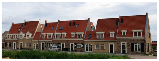
Figure 2.
Housing of the variation kind: adjacent buildings differ with respect to key features.
4. Materials and Methods
As Broadbent [36] pointed out, geometric representation of planning regulations returns permissible building envelopes. To test how this applies to the Netherlands and can be implemented in BIM, we needed a reasonably large, varied, and random sample that expressed what different Dutch municipalities prescribe for a certain class of buildings. Each case should describe the constraints contained in the regulations and their connections towards a spatial description, i.e., a partial model in BIM. Moreover, the cases should be processed in a way that is compatible with any project structure and within the capacities of an average designer.
The cases comprising this sample were provided by building management students who followed the same graduate information management course in subsequent years (2021 and 2022). They were asked to make models of small residential buildings in BIM solely on the basis of the applicable planning regulations (land-use plan and, if available, welstandsnota and monumentennota). The advantage of using students was that they worked under controlled conditions, with a specific workflow that followed closely the envisaged approach and avoided idiosyncratic interpretations of either information ordering or BIM. Moreover, as managers, they were more interested in the overall process and information rather than the design itself or the software. A number of the students had professional experience in AECO, which served for comparisons with existing BIM practices in the regular plenary discussions of work in progress that took place over the eight weeks of the exercise.
The main hypothesis was that, under uniformity regulations, this would return a complete representation of a fixed building envelope, certainly for terraced and semidetached buildings. Regulations of the flexible or of the variation kind would return a fuzzier representation of the building envelope that allowed more room for variation, although the constraints of the national Dutch building code would reduce this even further for all types of planning regulations. We considered also including constraints from the building code, so that the definition of the building envelope was made as complete as possible, but, in the end, the exercise was restricted to planning regulations for pragmatic reasons: as a corpus, they are significantly compacter than the building code, and more concerned with the overall form of a building and variable across the country, even within the same municipality. The exploration, furthermore, focused on low-rise residential buildings, mostly intended for single-family occupancy, which represent the majority of Dutch building stock and are specified with a higher precision than other types of buildings.
The workflow suggested to the students was one that can be accommodated within the scope of predesign information ordering in any project:
- Select a small residential plot anywhere in the world, preferably one well-known to them, e.g., that of their current residence or their family home. As most students who took the course were Dutch, it was expected that the majority would choose an urban or suburban plot for a single-family home in the Netherlands.
- Collect the planning regulations for that plot, starting from the national portal www.ruimtelijkplannen.nl (accessed on 27 December 2023) and extending the search to municipal websites, which often contained additional planning policy documents. In non-Dutch cases, it was assumed that applicable planning regulations were also accessible on the Internet. In all cases, the collected constraints were expected to include the following:
- Building dimensions;
- Building footprint (area, position in plot, etc.);
- Dimensions of building features (roofs, dormers, bay windows, etc.);
- Dimensions of additions and extensions.
- Connect the collected constraints and plot dimensions in a spreadsheet, so as to make explicit as many dimensions and relations as possible; e.g., calculate the footprint of a building if the regulations use only setbacks to define it. This should also reveal any missing information.
- Make a basic model for the known part of the building in BIM, using either massing elements (volumetric model) or building elements dimensioned and positioned according to the spreadsheet calculations. Students were advised to ignore the existing building and focus instead on what was allowed.
- Make the planning constraints explicit in the model and its setup, e.g., using dimension lines locked to the appropriate values.
Each case was examined separately by the teaching staff regarding the following:
- Veracity: Did students include all actual constraints for their plot? This involved tracking the sources for each plot and comparing them to what students reported.
- Comprehensiveness: How much of the building envelope could be produced on the basis of planning regulations. This (as well as the next two) was carried out by examining each model and comparing it to the verified spreadsheet.
- Coherence: Do planning regulations fit together to produce the building envelope?
- Consistency: Are all constraints specified in a compatible manner?
On a different level, the whole sample was evaluated with respect to the following:
- Efficacity: Does the proposed workflow return the expected results (i.e., models of the building envelope in BIM)?
- Consistency: Do the planning regulations of different municipalities stipulate similar constraints for the building envelope?
- BIM requirements: What is the level of skills necessary for modelling a building envelope on the basis of building constraints?
5. Results
Out of 112 students who produced usable results on a Dutch location, 94 chose one with regulations of the uniform kind, 5 of the flexible kind, and 13 of the variation kind (Table 2—see also Appendix A). The majority of studied cases concerned single-family homes, usually terraced (70), but also semidetached (14) or detached (21). Seven apartment blocks were also studied.
Table 2.
Classified results.
Planning constraints typically included the following:
- Fence height (important for the sense of community and privacy in a densely populated country): almost uniformly one metre for the front yard and two metres for the back and side yards.
- Building setbacks from the plot boundaries.
- Maximum building height (including the roof).
- Roof height, either directly given or indirectly through the roof pitch and the roof gutter height.
- Roof pitch, often as a bandwidth.
- Dormer number, dimensions, and location (on which side of the roof). In most cases, the dormer roof type was also specified (usually flat for urban areas and pitched in rural ones). Practically all cases also referred to local precedents.
- Bay window number and dimensions, usually with a degree of fuzziness that allowed room for design decisions. Typically, one or two bay windows were allowed with a total width expressed as a fraction or percentage of the width of the building façade. Here, again, references were made to precedent bay windows in the neighbourhood, as well as to storey height.
- Additions and extensions: these came in various forms, commonly including a two-metre-deep extension on the back façade and small outbuildings, usually with setbacks from the sides of the plot. The total area of all additions and extensions was usually a percentage of the unbuilt plot area, while their height was determined by the storey height.
The morphological constraints were a mixed bag. On one hand, there were clear constraints on specific elements, such as the roof pitch, and, on the other, vague goals, such as “urban cohesion”, with an unclear extent and, therefore, subject to interpretation by the authorities that issued a permit. Activities that required no permit, from the painting of houses to the construction of extensions, were generally not regulated with respect to morphology.
5.1. Connecting Constraints
Connecting the identified constraints in a spreadsheet returned an overview and specification of building features. As expected, the building footprint and its location in a plot were easily calculated in all cases of terraced and semidetached buildings (Table 3). The footprint of detached buildings was fuzzier but, nevertheless, calculable within a bandwidth defined by the maximum buildable area and the setbacks (Table 4). The same held for the extensions and additions to the main building.
Table 3.
Spreadsheet of planning constraints (uniformity kind, terraced housing—by R. van Tatenhove).
Table 4.
Spreadsheet of planning constraints (uniformity kind, detached housing—by N. Coes).
Clarity of the footprint was not limited to regulations of the uniform kind but was also applied to those of the variation kind. In the latter, dimensional variation mostly referred to the third dimension (the height of the building and its horizontal layers). In the horizontal dimensions, variation was primarily caused by the non-uniform frontage of the plots (Table 5).
Table 5.
Spreadsheet of planning constraints (variation kind, terraced housing—by M. Kocken).
The spreadsheets were instrumental in clarifying fuzzy values. Maximum building height was always explicit among the planning constraints but roof height was determined in various ways, through combinations of maximum building height, roof pitch (usually as a bandwidth), and gutter height, which could be calculated in the spreadsheet. In cases of the variation kind, where roof form was abstractly defined as dissimilar to adjacent properties, the combination of maximum height and footprint produced a bounding box for the building.
The benefits of connecting planning constraints in a spreadsheet were particularly evident in the specification of details, such as dormers, on which various constraints converged, often creating a confusing initial picture. Conflict resolution between setback values, dormer dimensions relative to roof dimension, maximum values, and the dimensions of precedent dormers in the neighbourhood generally returned a transparent and unambiguous conclusion.
5.2. Modelling in BIM
Most students had limited modelling skills in BIM. Many had difficulty with complex assemblies of building elements, for example, roofs with dormers and façades with bay windows. Volumetric models also proved hard to manipulate, as practically no student had prior exposure to massing studies in BIM. Nevertheless, the models students produced were generally precise and usable as specifications of the building envelope, certainly for terraced and semidetached housing under uniformity and variation regulations (Figure 3 and Figure 4).
Figure 3.
Volumetric model (uniformity kind, terraced housing—by T. van Os).
Figure 4.
Building model (uniformity kind, semidetached housing—by J. Schreuder).
In all models, the main building, all fences, and backyard extensions were clearly delineated. For most dormers, maximum sizes were used as the logical option to maximizing building volume (Figure 5). Bay windows and backyard additions or extensions were represented more tentatively with respect to position and height, again in the maximum permissible size (Figure 6).
Figure 5.
Dormer detail (by R. van Tatenhove).
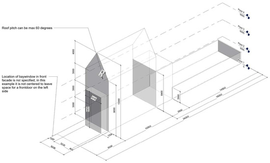
Figure 6.
Model with indicative bay window (by T. van Tienhoven).
Similarly indicative and linked to maximum sizes were the main building envelopes under flexible regulations, especially for detached housing. In these cases, the smaller the size of the plot was, the more discernible the options for building size and location became. Flexible regulations also allowed more scope for morphology, so alternative models were used to describe the range of available options (Figure 7).
Figure 7.
Alternatives under regulations of the flexible kind: pitched roof with dormers versus flat roof (by N. Verschoor).
5.3. Comparison to Other Countries
Seven students chose subjects in South Africa and countries of South America and Asia. The planning regulations on their plots were largely similar to those of the flexible kind in the Netherlands (Table 6). This suggests that Dutch regulations are more stringent than others and calls for further research, which could also clarify whether this is due to culture or density: respectively, Dutch norms of equality, or policies for avoiding the overexploitation of urban land and the resulting risks of urban deterioration.
Table 6.
Spreadsheet of planning regulations in Johannesburg, South Africa (by E. Seda).
5.4. Exploration and Creativity
In their reflection on the exercise, most students remarked that the exercise was an eye-opener concerning how much is predetermined in a design process. They observed that modelling the building envelope on the basis of planning regulations was easier than they had feared and gave them a better understanding of the many small challenges involved, as well as of the bigger challenge of combining these and client requirements in designing. A better understanding of the difference between tacit and overt information was instrumental in a shift from having to remember and mentally process planning regulations, as in other courses, to a less effortful understanding of the meaning of the regulations and their constraints, including the resolution of conflicts and ambiguities. A number of students dealing with flexible planning regulations started thinking in terms of variations and alternatives, while others pointed out that, even though, apparently, under uniformity regulations, much seemed fixed, they were no longer approaching the design as a repetition of one of the standard types of Dutch housing but were intrigued by combinations and conflicts that could give rise to new ideas.
6. Conclusions
6.1. Limitations
The choices of students left rural areas (which typically use flexible planning regulations) underrepresented but provided a decent picture of regulations aiming at either uniformity or variation (which represent the majority of plots in the Netherlands), as well as of the workflow and techniques of modelling in general. While the extensive Dutch uniformity regulations that specify building envelopes almost in full may be typical of relatively few countries, many planning constraints such as setbacks and references to local precedents [12] or roof pitch bandwidths [5] appear to be universal. Consequently, the proposed approach can be used to model at least parts of the building envelope and structure the rest, minimally through indicative visualizations, similarly to flexible planning regulations.
Regarding modelling, most of the students were BIM novices, and, therefore, prone to use models more as visualizations rather than information environments. Parametrization was beyond the capacities of most but the guidelines of the proposed workflow ensured transparency in the representation of most constraints. In all, the exercise was more than an academic activity that taught planning regulations and BIM to the students: it was a convincing simulation of predesign information ordering and the BIM setup that can be applied in practice and expanded to other kinds of constraints.
6.2. Workflow
At a practical level, the results of the exercise confirm that, for most land plots in the Netherlands, what can be built is largely predetermined and can, therefore, be made explicit before a design process. This has obvious consequences for both design and management: it produces clear constraints for the spatial layout, a definable bandwidth for the construction costs, and a generally narrow spectrum of possible solutions for many parts and aspects of a building (assuming one is inclined to adhere to the planning constraints). These can become even more specific if the planning regulations are combined with constraints from the building code and related legislation (storey height, stair sizes, dimensions of primary use spaces, presence and sizing of windows and doors, etc.).
Consequently, the workflow used in the exercise seems generally applicable to design and construction projects. Making known constraints explicit and linking them to each other in a spreadsheet removes many causes of overoptimism and other misunderstandings based on ignorance or vagueness. However, it is important that the constraints are expressed not only alphanumerically but also spatially, as discussed in the next subsection. Modelling them in BIM appears feasible in all cases, even when it produces indicative results.
Regarding the biases discussed in Section 2, the workflow makes the distinction between overt and tacit information clear and operational: what is explicit can be stated, calculated, and modelled; conflicts or grey areas are then resolved by designers who employ their professional skills and knowledge to this end. It also demonstrates how traditional (pre-computerization) predesign information ordering transforms into digital feedforward that keeps constraints transparent and explicit: rather than notes and sketches, the constraints are present in the setup of a model. Consequently, it also resolves issues of timeliness and information in compliance analysis: planning constraints cannot be ignored at any point because they are already present at the onset of a design process. Finally, even without constraints from other sources (building codes, briefs, precedents, etc.), the substantial amount of information available from the very beginning refutes the tabula rasa assumptions of time–effort distribution curves.
The explicit representation of constraints in BIM minimizes the scope for interpretation and reduces the danger of developing and testing unfeasible proposals. It also supports creativity by means of a thorough exploration that uses external representations that refresh and confront mental models and images. Creativity is further stimulated by the identification of key problems, e.g., conflicts between what is required in the brief and what is permitted on a particular plot. This allows for the anticipation of obstacles and timely action, e.g., asking for exemption from specific regulations before investing time and energy in a project. For lesser conflicts, feedforward amounts to guidance for relevant decisions, e.g., concerning the choice of roof form under variation regulations in relation to the user activities accommodated in the top floor.
The strong presence of feedforward makes feedback in compliance checks a final stage, more concerned with validation and verification than guidance. This relates to the magnitude and source of errors that are identified in this final check and the specificity of the feedback. For example, a dormer designed on the basis of feedforward in the proposed workflow is highly unlikely to have inappropriate dimensions or roof form (the most common causes for rejection by planning authorities). It is, however, possible to have ignored a remote precedent in the neighbourhood that is, nevertheless, deemed binding by the authorities (human error).
Feedforward also allows the workflow to be completely implemented in BIM, dispensing with intermittent processes produced by combinations of BIM and GIS or other systems [12]. This simplifies the computer use and shifts the emphasis to the design tasks at hand, with compliance checking consisting of an explicit frame (feedforward) and background control (feedback) in a single, meaningful design environment.
6.3. Modelling Issues
Modelling by novices always returns variable results but practically all students produced BIM files that minimally provided visual guidance to decision making: indicative configurations and general outlines that served as a reliable and informative starting point for the design of a building on the specific plot. The fuzziest models concerned cases under variation regulations, especially in new development areas. These models tended to be rather too abstract (essentially bounding boxes) because students failed to link building features to adjacent properties and determine which options were dissimilar to these properties and, therefore, open to them.
Despite references to the immediate context, not only in variation but also in uniformity regulations, as well as for listed buildings, students generally adopted a narrow frame on their own plot. It is telling that, even though all duly noted when local precedents superseded general rules, no student took the trouble to search in online photographs for such precedents and include them in their work as proof of compliance. This arguably reflects a general AECO tendency that passes as economy but can actually cause conflicts and delays, e.g., when a dormer or bay window is discovered to be different to local precedents. In the few cases that the context was present in the models, it supported a better understanding of what the regulations amounted to and of the relation between the particular building and its neighbourhood (Figure 8).
Figure 8.
Adjacent buildings added to model (uniform kind, terraced housing—by C. Swinnen).
Even though constraint programming was beyond most students, the explicit symbolic representation of BIM allowed some of them to link constraints to specific symbols, and, so, comprehend the intention and scope of the regulations, resulting in usable examples of how constraints could be explicitly integrated in the setup of a model (Figure 9).
Figure 9.
Volumetric model with integrated planning constraints (by E. Seda).
To the few with programming skills, the combination of constraints and, especially, regulations of the variation kind appeared amenable to parametrization. This resulted in attempts at parametric networks that could automatically calculate the building envelope of a building (Figure 10).
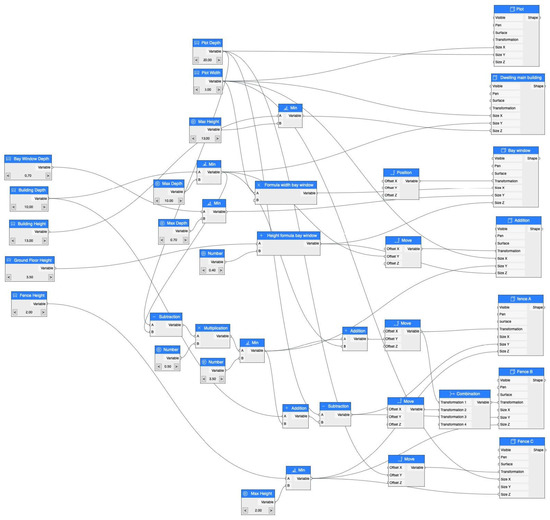
Figure 10.
Parametric network for the calculation of a building envelope of the variation kind in PARAM-O (by. J. Broekman).
Parametrization proved less easy in fuzzy situations, e.g., to bay windows, which usually can be either one or two, with a combined total width and flexible positioning within a zone in the façade. The same holds for the footprint of a building in planning regulations of the flexible kind, especially on the large plots encountered in rural municipalities. The indicative models used by students served, at best, as a visual reference and a foundation for tentative calculations of, for example, volumes, areas, and costs. Regrettably, the fuzzy modelling and reasoning capable of addressing such issues are still in their infancy in architectural design and, therefore, absent in BIM [64,65,66].
Overall, the modelling of planning constraints dispelled the erroneous assumptions that BIM is incapable of accommodating such constraints and that planning compliance requires GIS [12], suggesting that the latter is presumably simply because GIS is widely used to map planning regulations. It was also shown that it is not necessary to have a formal model for representing code and regulation elements in BIM [5]. It can be argued that, if such a formal model was integrated in the lexicographic standards on which BIM is based, code compliance would become better understandable to users, but a counterargument is that generic constraints suffice [1,17] and provide a degree of flexibility that agrees with design logic [14]. Relations to other buildings in the neighbourhood, including precedents, can also be covered in an economical manner by the level of modelling used, without the need for GIS [12].
7. Discussion
7.1. Design Analysis
Generate-and-test frequently leads to a sequential implementation of synthesis and analysis. What is described in the present paper suggests a symbiotic view, with feedforward guiding design actions and feedback evaluating their results. This is a symbiosis not only of synthesis and analysis, but also of a creative human designer and analytical automated assistant—something already familiar through, for example, grammar and syntax checking in text processing. Such symbiosis arguably plays to the strengths of either partner and establishes an effective and reliable approach to design computerization.
A key advantage of this approach is that, as feedforward prevents the violation of important constraints, the designs produced are valid as input to the analysis. Rather than having to correct models afterwards, feedforward moves a large part of model validation and planning compliance to the ‘generate’ stage and makes the subsequent testing a final confirmation unburdened by gross deviations. In contrast to time–effort distribution curves, this suggests that project information constitutes a bandwidth of options. This bandwidth starts with broad initial expectations, based on constraints like the ones discussed in this paper, and becomes progressively smaller as decisions are taken in the course of a design process.
7.2. Analysis in BIM
In design analysis, we can distinguish between two main levels of abstraction. The first concerns the whole design or big parts of it and involves general goals and overall performance, e.g., energy consumption or fire safety. The second level concerns discrete things and their properties, for example, minimum room height or minimum doorway width. The two levels are interconnected: fire egress, for example, involves chains of discrete things, such as rooms and doors, some of which must be evaluated separately (e.g., door width and fire resistance).
BIM supports the first level by its completeness: all information required as input for an analysis is normally present in a model, so that overall performance can be calculated. The second level is even easier to implement, either through rules that evaluate specific symbols, properties, and relations, or through constraints placed on these. Accessibility constraints, for example, mean that door types narrower than the norm should not be eligible for a particular design. These doors, therefore, should be filtered out a priori in a BIM editor, i.e., be unavailable for use in that design. Such forms of feedforward deserve more attention and wider implementation, especially if carried out in a transparent and insightful way that explains the constraints and their effects, therefore also provoking innovation that challenges them. Parametrization can ensure that explicit constraints are transparently applied in a model [67]: expressing the constraints as external parameters on symbol properties supports the adjustment of variable values (e.g., wall height) or the rejection of fixed ones (e.g., fire resistance of a door).
Planning regulations typically belong to the second level, so they profit from feedforward that places specific constraints on particular symbols, properties, and relations. Their implementation in BIM beyond the largely visual indications produced by the students in this exercise is a subject for further research. On one hand, one can use visualizations of permissible building envelopes as background elements, similarly to plot features: reference and guidance for the interactive positioning and dimensioning parts of the design. Parametric and constraint propagation networks, on the other hand, add to the intelligence of the model through behaviours drawn from the planning constraints, e.g., not allowing external walls to move into a setback zone. A combination of the two is arguably necessary because visualizations of a building envelope add transparency and meaning to behaviours and their underlying rules.
7.3. Wicked, Ill-Defined, and Open-Ended
There is a lot of literature on the wicked or ill-defined nature of design problems. While the exploration presented in this paper says little about the fundamental character of designing, it demonstrates that the open-endedness of design problems can also be attributed to poor specification. If planning regulations specify so much of a design as in the residential properties discussed here, relying on the designer’s tacit knowledge of them does little to reduce error and uncertainty in decision making and communication. Rather than entrusting the interpretation of planning regulations to the cognitive processes of designers, we should, therefore, make such constraints explicit in design representations and use them to guide design. Knowing the permissible building envelope frees designers from certain concerns and creates a clear frame for the remaining ones. Reversely, if designers feel they should challenge the constraints underlying a restrictive building envelope, they can only profit from knowing exactly what they need to confront and its derivation. The character of the resulting and remaining problems may still be wicked or ill-defined but the constraints that surround them help define solution spaces and provide clear criteria for synthesis and analysis in the explorations suggested in creativity studies.
7.4. Design Preliminaries and Creativity
Even mediocre models produced by novices with little knowledge of planning constraints and limited experience with BIM qualify as explorations of planning constraints and their spatial expressions. This allows the identification of the pieces of the puzzle and their general disposition without the pressures of having to produce an immediate solution. It is a process that may take time but is highly rewarding in complex situations or when creativity and innovation are the goals [46].
Clear framing and familiarization are essential in design because, although design problems are typically considered ill-defined, research into creativity suggests that this is frequently due to the omission of critical information, such as evaluation criteria, which turns well-defined problems into ill-defined ones [37]. Such information not only helps understand performance goals (e.g., what is meant by “zero energy”) but also guides decision making (e.g., which passive or active energetic devices are applicable in a given situation).
7.5. Future Work
The results of the exercise suggest that designers should be trained in practical matters of feedforward in BIM, combined with explicit predesign information ordering: extracting the constraints of a problem and including them in the setup of a model should be encouraged and valued, not merely as good information management, but as an essential step in creative problem solving. Collecting what is known about the problem, giving it a spatial representation, and exploring its facets are clearly within the capacities of most students and could, therefore, enrich BIM courses towards a more designerly direction. In practice, predesign, design, and modelling can similarly move closer together in workflows such as the one used here. Rather than starting to use BIM once a fundamental design has been decided, one can deploy BIM early and in a more explorative manner: towards, first, understanding the design problem, and then using the knowledge acquired through the explorations to achieve higher effectiveness, efficiency, or innovation.
Regarding BIM software, modelling planning constraints makes evident the necessity of fuzzy representations that allow designers to work with interval or otherwise non-crisp values. Such representations are arguably beyond what can be achieved with the current means and methods of parametric design and, therefore, require the radical redevelopment of computational design representations, in a direction that makes them compatible with the mental representations and informal sketches of designers. This could be an essential move for supporting, in full, users’ cognitive processes and bridging the gaps between design stages (and the corresponding abstraction levels).
Funding
This research received no external funding.
Data Availability Statement
Inquiries about the materials used in the study can be directed to the corresponding author.
Acknowledgments
Thanks go to the students who followed course AR2MBE021 (Building Information Management) at Delft University of Technology in 2021 and 2022, and, in particular to Zisis Vomvas, who assisted with the setup of the exercise, and Marnix Goossens, who compiled the first catalogue of results.
Conflicts of Interest
The author declares no conflict of interest.
Appendix A
Table A1.
Overview of student results (including main building features).
Table A1.
Overview of student results (including main building features).
| Student ID | Country | Municipality | Plan Type | Type | Setback Front | Setback Side | Setback Back | Max Width | Max Depth | Max Footprint | Max Area | Gutter Height | Roof Pitch | Roof Height |
|---|---|---|---|---|---|---|---|---|---|---|---|---|---|---|
| 5258901 | Colombia | Bogota | Terraced | 3.5 | - | 3.0 | 9.0 | 26.0 | 163.8 | 491.4 | - | - | 7.5 | |
| 5137489 | Colombia | Bogotá | Detached | 8.0 | 7.0 | 7.0 | 90.7 | 203.3 | 9222.0 | - | - | - | 25.0 | |
| 5264782 | Costa Rica | Moravia | Detached | 2.0 | 3.0 | 3.0 | 20.5 | 62.1 | 892.7 | 1785.5 | - | - | 7.0 | |
| 5340551 | Ecuador | Cuenca | Detached | 5.0 | 3.0 | 3.0 | 11.0 | 26.7 | 155.3 | - | - | 25.00% | 13.4 | |
| 5370891 | Iran | Tehran | Detached | 6.6 | - | - | 10.0 | 21.4 | 145.2 | - | - | - | 12.3 | |
| 4663691 | The Netherlands | Amersfoort | Uniform | Semidetached | - | - | - | - | - | 82.5 | - | - | 45.00% | - |
| 593731 | The Netherlands | Amersfoort | Uniform | Terraced | 4.0 | - | - | 5.0 | 15.0 | 30.0 | - | - | 30.00% | - |
| 4717317 | The Netherlands | Amstelveen | Uniform | Terraced | - | - | 14.0 | 6.0 | 22.0 | 48.0 | - | 6.0 | 60.00% | 10.0 |
| 4850483 | The Netherlands | Amstelveen | Uniform | Terraced | 2.5 | - | 13.0 | 5.5 | 25.5 | 55.0 | - | - | 60.00% | 10.0 |
| 4608488 | The Netherlands | Amstelveen | Uniform | Terraced | - | - | 10.8 | 5.6 | 20.1 | - | - | 7.0 | 40.00% | 10.0 |
| 4476727 | The Netherlands | Amsterdam | Uniform | Apartment | - | - | - | - | 12.8 | - | - | 15.0 | - | 18.0 |
| 4443543 | The Netherlands | Amsterdam | Uniform | Terraced | 6.0 | - | 6.0 | 8.0 | 33.0 | 192.6 | - | - | - | 9.0 |
| 4602323 | The Netherlands | Amsterdam | Uniform | Terraced | - | - | 10.3 | 9.0 | 20.0 | 44.5 | 133.5 | - | - | Max 9 m at front, 6 m at back |
| 4687744 | The Netherlands | Bergen | Variation | Detached | 6.0 | 3.0 | 12.0 | 15.0 | 25.0 | 70.0 | 210.0 | - | 40.00% | 12.5 |
| 4459849 | The Netherlands | Berkel en Rodenrijs | Uniform | Detached | 4.0 | - | - | 13.6 | 25.0 | - | - | 6.5 | 30–60% | 12.0 |
| 4498496 | The Netherlands | Blaricum | Variation | Semidetached | 8.0 | - | 8.0 | 10.0 | 25.0 | - | - | 4.0 | - | 8.0 |
| 4782720 | The Netherlands | Boxmeer | Variation | Terraced | 1.0 | - | - | 6.0 | 18.0 | 60.0 | - | 6.5 | 35.00% | 10.0 |
| 4826671 | The Netherlands | Breestraat 4 | Uniform | Detached | - | 1.0 | - | 19.0 | 18.0 | - | - | - | - | 9.0 |
| 5265711 | The Netherlands | Bunnik | Uniform | Terraced | 5.0 | - | - | 6.0 | 30.0 | - | - | - | 60.00% | 10.0 |
| 4731131 | The Netherlands | Capelle a/d IJssel | Uniform | Terraced | - | - | - | - | - | 70.0 | - | - | - | 15.0 |
| 4837886 | The Netherlands | De Bilt | Uniform | Detached | 16.0 | 3.0 | 13.0 | 15.0 | 50.0 | 96.0 | - | 7.0 | - | 11.0 |
| 4714415 | The Netherlands | De Bilt | Uniform | Semidetached | - | - | 18.0 | 11.0 | 30.3 | - | - | - | 41.50% | 8.5 |
| 4686640 | The Netherlands | De Bilt | Uniform | Terraced | - | - | 14.5 | 14.0 | 9.0 | 48.0 | - | - | 60.00% | 10.0 |
| 4853342 | The Netherlands | De Ronde Venen | Uniform | Detached | - | - | - | - | - | - | 116.0 | 4.0 | 40.00% | 9.0 |
| 9842023 | The Netherlands | De Wolden | Variation | Detached | 3.0 | - | 9.0 | 30.0 | 40.0 | 80.0 | - | 3.0 | 15.00% | 7.0 |
| 5223318 | The Netherlands | Delft | Uniform | Apartment | - | - | 9.0 | 7.5 | 22.0 | 97.5 | - | 17.0 | 30.00% | 20.0 |
| 4687965 | The Netherlands | Delft | Uniform | Apartment | 1.0 | - | - | 8.0 | 24.0 | - | - | 10.0 | - | 12.0 |
| 4495071 | The Netherlands | Delft | Uniform | Apartment | - | - | 1.0 | 8.0 | 24.0 | - | - | - | - | 12.0 |
| 4697162 | The Netherlands | Delft | Uniform | Detached | - | At least 2× height of building | - | 30.0 | 55.0 | 330.0 | - | - | 25–55% | 9.0 |
| 4444698 | The Netherlands | Delft | Uniform | Terraced | - | - | - | 4.5 | 32.5 | 152.0 | 146.0 | 8.5 | 45–75% | 12.5 |
| 5252118 | The Netherlands | Delft | Uniform | Terraced | 5.5 | - | 10.0 | 7.0 | 25.0 | 66.5 | - | - | 60.00% | 9.0 |
| 5216265 | The Netherlands | Delft | Uniform | Terraced | 12.0 | - | - | 10.0 | 35.0 | 75.0 | 230.0 | 8.0 | 35.00% | 12.0 |
| 4558693 | The Netherlands | Delft | Uniform | Terraced | - | - | 12.0 | 4.0 | 24.0 | 48.0 | 144.0 | 6.0 | 30.00% | 10.0 |
| 4370570 | The Netherlands | Delft | Uniform | Terraced | - | - | 10.0 | 8.1 | 19.2 | 74.5 | - | - | 30.00% | 13.0 |
| 4631218 | The Netherlands | Delft | Uniform | Terraced | - | - | - | 3.8 | 10.0 | 38.0 | 149.0 | - | - | 14.0 |
| 4653955 | The Netherlands | Delft | Uniform | Terraced | 1.5 | - | 12.0 | 5.7 | 22.0 | 56.5 | - | 5.4 | 30.00% | - |
| 4489454 | The Netherlands | Delft | Uniform | Terraced | - | - | 16.0 | 4.8 | 30.3 | 67.7 | - | 9.0 | 45–75% | - |
| 4644026 | The Netherlands | Delft | Uniform | Terraced | - | - | 2.0 | 5.0 | 10.0 | 40.0 | - | - | 44.00% | 9.0 |
| 4672313 | The Netherlands | Delft | Uniform | Terraced | - | - | 4.5 | 4.8 | 30.3 | - | - | - | 30.00% | 12.0 |
| 5635047 | The Netherlands | Delft | Uniform | Terraced | - | - | - | 8.4 | 24.6 | - | - | 6.0 | - | 10.0 |
| 4455428 | The Netherlands | Delft | Uniform | Terraced | - | - | 8.0 | 5.8 | 32.8 | - | 142.3 | 6.0 | 45.00% | 9.0 |
| 4382226 | The Netherlands | Delft | Uniform | Terraced | - | - | 12.0 | 8.0 | 24.0 | 120.0 | 384.0 | - | - | 12.0 |
| 4598105 | The Netherlands | Delft | Uniform | Terraced | 2.5 | - | - | 5.7 | 18.7 | 57.0 | - | - | 30.00% | 10.0 |
| 4554086 | The Netherlands | Delft | Uniform | Terraced | 6.0 | - | 18.0 | 5.0 | 34.0 | 50.0 | 243.0 | 9.0 | 60.00% | 13.0 |
| 5505003 | The Netherlands | Delft | Uniform | Terraced | 1.0 | 1.0 | 1.0 | 9.5 | 13.0 | 114.0 | - | - | 45.00% | 8.0 |
| 5320607 | The Netherlands | Delft | Uniform | Terraced | 2.0 | - | - | 8.8 | 20.6 | 87.9 | 351.6 | - | - | 14.0 |
| 5377188 | The Netherlands | Delft | Uniform | Terraced | - | - | 12.0 | 6.0 | 24.0 | 72.0 | - | - | 30.00% | 10.0 |
| 4712749 | The Netherlands | Delft | Variation | Terraced | - | - | 9.0 | 6.0 | 19.0 | 60.0 | - | - | - | 13.0 |
| 4647963 | The Netherlands | Delft | Variation | Terraced | - | - | - | 5.0 | 20.0 | - | - | - | - | 13.0 |
| 4447778 | The Netherlands | Delft | Variation | Terraced | - | - | 12.0 | 8.0 | 24.0 | 96.0 | - | - | 30.00% | 12.0 |
| 5260272 | The Netherlands | Delft | Variation | Terraced | - | - | - | 4.0 | 10.0 | 40.0 | - | - | - | 14.0 |
| 4656954 | The Netherlands | Den Haag | Uniform | Apartment | - | - | 5.0 | 8.0 | 12.0 | 96.0 | - | 7.0 | - | 10.0 |
| 4450884 | The Netherlands | Den Haag | Uniform | Semidetached | 16.5 | - | 14.5 | 11.0 | 39.0 | 64.0 | - | 7.0 | 56.30% | 13.0 |
| 4718941 | The Netherlands | Den Haag | Uniform | Terraced | 3.0 | - | - | 5.0 | 22.0 | 65.0 | - | - | - | 9.0 |
| 4713095 | The Netherlands | Den Haag | Uniform | Terraced | 2.0 | - | 6.0 | 5.0 | 10.0 | 50.0 | 150.0 | - | - | 9.0 |
| 5367425 | The Netherlands | Den Haag | Uniform | Terraced | 5.5 | - | - | 7.0 | 17.5 | 84.0 | - | - | 30.00% | 11.0 |
| 4822544 | The Netherlands | Den Hoorn | Uniform | Terraced | 3.0 | 3.0 | 3.0 | 8.0 | 24.0 | - | - | 6.0 | 30–60% | - |
| 4487494 | The Netherlands | Deventer | Uniform | Terraced | - | - | 9.6 | 6.0 | 20.5 | - | - | - | 30.00% | 7.8 |
| 5417465 | The Netherlands | Diepenveen | Uniform | Detached | - | 1.0 | - | - | - | 96.0 | - | 4.5 | 20–55% | 10.0 |
| 4475410 | The Netherlands | Doetinchem | Uniform | Semidetached | 3.0 | - | - | 4.5 | 22.0 | 45.4 | - | 4.5 | 30–60% | 9.0 |
| 5075610 | The Netherlands | Drechterland | Variation | Detached | 13.0 | 1.0 | 10.0 | 39.0 | 34.0 | 99.0 | 297.0 | 3.5 | 30–70% | 10.0 |
| 4960939 | The Netherlands | Eindhoven | Uniform | Terraced | - | - | 4.3 | 5.4 | 9.9 | 87.5 | - | 5.7 | 45.00% | 11.0 |
| 4844416 | The Netherlands | Elburg | Variation | Detached | - | - | - | 4.0 | 11.6 | 46.4 | - | - | - | 3.5 |
| 4681940 | The Netherlands | Epe | Uniform | Detached | 3.0 | 3.0 | 3.0 | 16.5 | 28.0 | 181.3 | 6.0 | 25–60% | 9.0 | |
| 5229960 | The Netherlands | Etten-Leur | Uniform | Terraced | - | - | 10.0 | 5.4 | 12.0 | 64.8 | - | - | 30.00% | 10.0 |
| 4449711 | The Netherlands | Gilze en Rijen | Uniform | Terraced | 2.0 | - | 2.0 | 6.8 | 26.6 | 125.7 | 150.0 | 6.0 | 40.00% | 9.0 |
| 4556585 | The Netherlands | Gorinchem | Flexible | Detached | - | - | - | 10.0 | 16.0 | 160.0 | - | 10.0 | - | 10.0 |
| 4720873 | The Netherlands | Gouda | Uniform | Terraced | 3.4 | - | - | 6.7 | 22.8 | 57.6 | - | 6.0 | 33.69% | 10.0 |
| 4874439 | The Netherlands | Groningen | Uniform | Semidetached | 2.0 | 3.0 | 3.0 | - | - | - | - | 6.0 | 30–70% | 12.0 |
| 4669177 | The Netherlands | Groningen | Uniform | Semidetached | 5.0 | - | 8.5 | 13.0 | 25.5 | 120.0 | - | - | 60.00% | 11.0 |
| 4565673 | The Netherlands | Groningen | Variation | Detached | - | 3.0 | - | 23.0 | 24.0 | 88.5 | - | - | 44.00% | 7.4 |
| 4445740 | The Netherlands | Haarlem | Uniform | Terraced | 2.5 | - | 10.0 | 6.0 | 22.0 | 57.0 | - | 6.0 | 30–70% | 10.0 |
| 4722949 | The Netherlands | Haarlemmermeer | Uniform | Detached | - | - | - | - | - | - | - | - | 60.00% | 9.0 |
| 4439740 | The Netherlands | Heusden | Flexible | Terraced | ||||||||||
| 5470587 | The Netherlands | Houten | Uniform | Terraced | - | - | - | - | - | - | - | - | - | - |
| 4693280 | The Netherlands | Huizen | Uniform | Terraced | - | - | - | 6.0 | 32.0 | 76.8 | - | 6.0 | 55.00% | 11.0 |
| 4587693 | The Netherlands | IJsselstein | Uniform | Terraced | 2.0 | - | - | 6.0 | 23.0 | - | - | 6.0 | - | 9.0 |
| 4709268 | The Netherlands | IJsstelstein | Uniform | Terraced | - | - | - | 5.0 | 11.0 | 55.0 | - | - | 45.00% | 9.7 |
| 4273834 | The Netherlands | Kaag en Braassem | Uniform | Detached | 3.1 | - | - | 20.0 | 21.0 | - | 420.0 | 4.0 | - | 7.5 |
| 5423902 | The Netherlands | Kapelle | Uniform | Semidetached | - | - | 5.0 | 11.0 | 31.5 | - | - | 5.0 | - | 7.0 |
| 4708105 | The Netherlands | Leiden | Uniform | Terraced | 2.5 | - | - | 5.5 | 25.5 | 60.5 | - | 7.0 | 45.00% | 10.0 |
| 4711262 | The Netherlands | Lelystad | Uniform | Terraced | 2.0 | - | 7.0 | 5.6 | 22.0 | 72.8 | 218.4 | - | - | 11.0 |
| 5221404 | The Netherlands | Middelburg | Uniform | Terraced | 5.0 | - | - | 6.0 | 25.0 | 60.0 | - | 60.0 | - | 10.0 |
| 4452348 | The Netherlands | Oegstgeest | Uniform | Terraced | - | - | - | 5.9 | 10.3 | 60.8 | 182.3 | 6.0 | - | 10.0 |
| 4590236 | The Netherlands | Oirschot | Uniform | Terraced | 3.0 | - | - | 8.0 | 25.0 | 200.0 | - | 8.0 | 25–65% | 10.0 |
| 4661257 | The Netherlands | Oisterwijk | Flexible | Detached | 1.0 | 5.0 | - | 12.0 | 25.7 | 137.8 | - | 3.5 | 45.00% | 9.0 |
| 4690710 | The Netherlands | Oldebroek | Uniform | Detached | - | - | - | - | - | - | - | 3.5 | -% | 8.0 |
| 4678087 | The Netherlands | Oosterhout | Uniform | Terraced | 1.9 | - | - | 9.4 | 7.3 | - | - | - | - | 9.0 |
| 5509262 | The Netherlands | Oss | Uniform | Terraced | 2.0 | - | - | 5.8 | 22.0 | 69.6 | - | 6.0 | 31.00% | 9.0 |
| 4477480 | The Netherlands | Overbetuwe | Variation | Detached | - | - | 12.0 | 63.0 | 23.0 | 162.0 | 239.0 | - | 30.00% | 10.0 |
| 4658469 | The Netherlands | Pijnacker-Nootdorp | Uniform | Semidetached | 2.0 | - | - | 9.0 | 25.0 | - | - | - | 30.00% | 10.0 |
| 4445171 | The Netherlands | Pijnacker-Nootdorp | Uniform | Terraced | - | - | 4.0 | 5.0 | 20.0 | 80.0 | - | - | 30.00% | 9.0 |
| 5270693 | The Netherlands | Pijnacker-Nootdorp | Uniform | Terraced | - | - | 15.0 | 8.0 | 26.0 | 88.0 | - | - | 10.00% | 10.0 |
| 4579968 | The Netherlands | Pijnacker-Nootdorp | Uniform | Terraced | - | - | - | 5.5 | 23.5 | 52.3 | - | 7.0 | - | 10.0 |
| 5308384 | The Netherlands | Pijnacker-Nootdorp | Uniform | Terraced | - | - | - | 10.0 | 60.0 | - | - | - | - | 10.0 |
| 4391411 | The Netherlands | Purmerend | Uniform | Terraced | 3.5 | - | 14.0 | 5.0 | 26.0 | 42.5 | - | - | - | 9.0 |
| 5357462 | The Netherlands | Rijswijk | Variation | Detached | 3.0 | 3.0 | 6.0 | - | - | 169.6 | 254.5 | 3.0–7.0 | 45.00% | 10.0 |
| 4379381 | The Netherlands | Roermond | Uniform | Semidetached | - | 8.0 | 32.0 | 15.0 | 42.0 | - | 240.4 | 6.0 | 28.96% | 9.0 |
| 4562275 | The Netherlands | Rotterdam | Uniform | Apartment | - | - | - | 7.0 | 20.0 | 140.0 | - | - | 25–75% | 11.8 |
| 4369416 | The Netherlands | Rotterdam | Uniform | Apartment | - | - | 17.0 | 13.0 | 32.0 | 195.0 | - | - | - | 13.0 |
| 4441869 | The Netherlands | Schiedam | Uniform | Semidetached | - | - | 12.0 | 9.7 | 20.0 | 193.0 | - | - | 30.00% | 12.0 |
| 4707036 | The Netherlands | Schiedam | Uniform | Terraced | - | - | - | 7.5 | 11.5 | 50.0 | 200.0 | - | 45–60% | 12.0 |
| 4576977 | The Netherlands | Schouwen-Duiveland | Uniform | Semidetached | 4.0 | - | - | 10.4 | 30.0 | - | - | 6.0 | 38.00% | 10.0 |
| 5248965 | The Netherlands | Spaarnebuiten | Flexible | Detached | 1.0 | 1.0 | 1.0 | - | - | 55% of plot | - | - | - | 11.0 |
| 5243572 | The Netherlands | Spijkenisse | Uniform | Terraced | 4.0 | - | 12.0 | 5.0 | 20.0 | 45.0 | - | 6.0 | - | 9.0 |
| 5479029 | The Netherlands | Tiel | Uniform | Semidetached | 6.5 | - | - | 9.7 | 31.8 | 67.0 | - | 6.0 | - | 10.0 |
| 5407788 | The Netherlands | Venlo | Uniform | Terraced | 3.0 | - | 14.5 | 8.0 | 26.5 | - | - | - | 60.00% | 10.0 |
| 4869427 | The Netherlands | Vlist | Uniform | Terraced | 2.0 | - | 10.0 | 5.0 | 21.0 | 45.0 | - | 7.0 | 41.63% | 11.0 |
| 5190770 | The Netherlands | Voorburg | Uniform | Terraced | 7.5 | - | - | 6.0 | 27.5 | 60.0 | - | - | - | 9.5 |
| 4532740 | The Netherlands | Wateringen | Uniform | Terraced | 1.0 | - | - | 5.0 | 21.0 | - | - | 6.0 | - | 10.0 |
| 4594215 | The Netherlands | Woerden | Uniform | Terraced | 2.0 | - | 8.0 | 5.0 | 8.0 | 60.0 | - | - | - | 9.0 |
| 5184614 | The Netherlands | Woerden | Uniform | Terraced | 4.0 | - | - | 5.8 | 24.0 | 58.0 | - | 5.0 | - | 7.0 |
| 4695682 | The Netherlands | Zaandam | Uniform | Terraced | 3.0 | - | 8.0 | 5.5 | 21.0 | 55.0 | - | - | 30.00% | 9.0 |
| 4867521 | The Netherlands | Zoetermeer | Flexible | Detached | - | 1.0 | - | 14.0 | 24.0 | - | - | - | 30.00% | 10.0 |
| 4731093 | The Netherlands | Zwijndrecht | Uniform | Semidetached | 2.5 | - | 12.0 | 10.0 | 27.0 | 125.0 | - | - | 30.00% | 12.0 |
| 4534522 | The Netherlands | Zwolle | Uniform | Terraced | 1.0 | - | 19.0 | 9.0 | 42.0 | 207.0 | 414.0 | - | - | 6.5 |
| 4558332 | The Netherlands | Zwolle | Uniform | Terraced | - | - | 5.0 | 5.9 | 15.0 | 59.6 | - | 6.0 | 30–50% | 9.0 |
| 5199468 | South Africa | Johannesburg | Detached | 1.0 | 1.0 | 1.0 | - | - | 297.6 | - | - | 22–45% | - | |
| 5339117 | Thailand | Bangkok | Detached | 3.0 | 2.0 | 3.0 | 26.0 | 39.0 | 333.0 | - | - | - | 9.0 |
References
- Amor, R.; Dimyadi, J. The promise of automated compliance checking. DIBE 2021, 5, 100039. [Google Scholar] [CrossRef]
- Andrich, W.; Daniotti, B.; Pavan, A.; Mirarchi, C. Check and Validation of Building Information Models in Detailed Design Phase: A Check Flow to Pave the Way for BIM Based Renovation and Construction Processes. Buildings 2022, 12, 154. [Google Scholar] [CrossRef]
- Guler, D.; Yomralioglu, T. A reformative framework for processes from building permit issuing to property ownership in Turkey. Land Use Policy 2021, 101, 105115. [Google Scholar] [CrossRef]
- Kim, I.; Choi, J.; Teo, E.A.L.; Sun, H. Development of kbim e-submission prototypical system for the openbim-based building permit framework. J. Civ. Eng. Manag. 2020, 26, 744–756. [Google Scholar] [CrossRef]
- Macit İlal, S.; Günaydın, H.M. Computer representation of building codes for automated compliance checking. Autom. Constr. 2017, 82, 43–58. [Google Scholar] [CrossRef]
- Noardo, F.; Ellul, C.; Harrie, L.; Overland, I.; Shariat, M.; Arroyo Ohori, K.; Stoter, J. Opportunities and challenges for GeoBIM in Europe: Developing a building permits use-case to raise awareness and examine technical interoperability challenges. J. Spat. Sci. 2020, 65, 209–233. [Google Scholar] [CrossRef]
- Noardo, F.; Guler, D.; Fauth, J.; Malacarne, G.; Mastrolembo Ventura, S.; Azenha, M.; Olsson, P.-O.; Senger, L. Unveiling the actual progress of Digital Building Permit: Getting awareness through a critical state of the art review. Build. Environ. 2022, 213, 108854. [Google Scholar] [CrossRef]
- Shahi, K.; McCabe, B.Y.; Shahi, A. Framework for Automated Model-Based e-Permitting System for Municipal Jurisdictions. J. Manag. Eng. 2019, 35, 04019025. [Google Scholar] [CrossRef]
- Tan, X.; Hammad, A.; Fazio, P. Automated Code Compliance Checking for Building Envelope Design. J. Comput. Civ. Eng. 2010, 24, 203–211. [Google Scholar] [CrossRef]
- Yang, Q.Z.; Xu, X. Design knowledge modeling and software implementation for building code compliance checking. Build. Environ. 2004, 39, 689–698. [Google Scholar] [CrossRef]
- Zhang, J.; El-Gohary, N.M. Integrating semantic NLP and logic reasoning into a unified system for fully-automated code checking. Autom. Constr. 2017, 73, 45–57. [Google Scholar] [CrossRef]
- Demir Altıntaş, Y.; Ilal, M.E. Loose coupling of GIS and BIM data models for automated compliance checking against zoning codes. Autom. Constr. 2021, 128, 103743. [Google Scholar] [CrossRef]
- Koutamanis, A. Building Information—Representation and Management: Principles and Foundations for the Digital Era; TU Delft OPEN: Delft, The Netherlands, 2022. [Google Scholar] [CrossRef]
- Koutamanis, A.; Dainty, A.; Kvan, T.; Turk, Ž. The Enigma of BIM. Archit. Struct. Constr. 2021, 3, 1–9. [Google Scholar] [CrossRef]
- Lee, H.; Lee, J.-K.; Park, S.; Kim, I. Translating building legislation into a computer-executable format for evaluating building permit requirements. Autom. Constr. 2016, 71, 49–61. [Google Scholar] [CrossRef]
- Nawari, N.O.; Alsaffar, A. The Role of BIM in Simplifying Construction Permits in Kuwait. In AEI 2017; ASCE: Washington, DC, USA, 2017; pp. 855–866. [Google Scholar] [CrossRef]
- Fauth, J.; Bloch, T.; Noardo, F.; Nisbet, N.; Kaiser, S.-B.; Nørkjær Gade, P.; Tekavec, J. Taxonomy for building permit system—Organizing knowledge for building permit digitalization. Adv. Eng. Inform. 2024, 59, 102312. [Google Scholar] [CrossRef]
- Bovill, C. Architectural Design: Integration of Structural and Environmental Systems; Van Nostrand Reinhold: New York, NY, USA, 1991; pp. 9–213. [Google Scholar]
- Kahneman, D. Thinking, Fast and Slow, 1st ed.; Farrar, Straus and Giroux: New York, NY, USA, 2013; 499p. [Google Scholar]
- Rietveld, E.; Kiverstein, J. A Rich Landscape of Affordances. Ecol. Psychol. 2014, 26, 325–352. [Google Scholar] [CrossRef]
- Withagen, R.; Araújo, D.; de Poel, H.J. Inviting affordances and agency. New Ideas Psychol. 2017, 45, 11–18. [Google Scholar] [CrossRef]
- Polanyi, M. The Tacit Dimension; Routledge & K. Paul: London, UK, 1967; pp. 11–108. [Google Scholar]
- Polanyi, M. Personal Knowledge: Towards a Post-Critical Philosophy; Routledge: London, UK, 1997; 428p. [Google Scholar]
- Henderson, K. On Line and on Paper: Visual Representations, Visual Culture, and Computer Graphics in Design Engineering; (Inside technology); MIT Press: Cambridge, MA, USA, 1999; pp. 10–237. [Google Scholar]
- Pressman, A. Design Thinking: A Guide to Creative Problem Solving for Everyone; Routledge: London, UK; New York, NY, USA, 2019; pp. 22–154. [Google Scholar]
- Brereton, M. Distributed Cognition in Engineering Design: Negotiating between Abstract and Material Representations. In Design Representation; Goldschmidt, G., Porter, W.L., Eds.; Springer: London, UK, 2004; pp. 83–103. [Google Scholar] [CrossRef]
- Sacks, R.; Eastman, C.; Lee, G.; Teicholz, P. BIM Handbook, 3rd ed.; Wiley: Hoboken NJ, USA, 2018. [Google Scholar] [CrossRef]
- Paulson, B.C. Designing to Reduce Construction Costs. J. Constr. Div. 1976, 102, 587–592. [Google Scholar] [CrossRef]
- MacLeamy, P. Collaboration, Integrated Information and the Project Lifecycle in Building Design, Construction and Operation; CURT: Cincinnati, OH, USA, 2004; p. 20. [Google Scholar]
- Lu, W.; Fung, A.; Peng, Y.; Liang, C.; Rowlinson, S. Demystifying Construction Project Time-Effort Distribution Curves: BIM and Non-BIM Comparison. J. Manag. Eng. 2015, 31, 04015010. [Google Scholar] [CrossRef]
- Chabris, C.F.; Simons, D.J. The Invisible Gorilla: And Other Ways Our Intuitions Deceive Us, 1st ed.; Crown: New York, NY, USA, 2010; pp. 11–306. [Google Scholar]
- Vigen, T. Spurious Correlations, 1st ed.; Hachette Books: New York, NY, USA, 2015; pp. 15–189. [Google Scholar]
- Sacks, R.; Gurevich, U.; Shrestha, P. A review of Building Information Modeling protocols, guides and standards for Large construction clients. J. Inf. Technol. Constr. 2016, 21, 479–503. [Google Scholar]
- Koutamanis, A. Briefing and Building Information Modelling: Potential for integration. Int. J. Archit. Comput. 2017, 15, 119–133. [Google Scholar] [CrossRef]
- Flyvbjerg, B. Over Budget, Over Time, Over and Over Again: Managing Major Projects. In The Oxford Handbook of Project Management; Morris, P.W.G., Pinto, J., Söderlund, J., Eds.; Oxford University Press: Oxford, UK, 2011. [Google Scholar] [CrossRef]
- Broadbent, G. Design in Architecture, 2nd ed.; David Fulton: London, UK, 2000. [Google Scholar]
- Weisberg, R. The study of creativity: From genius to cognitive science. Int. J. Cult. Policy 2010, 16, 235–253. [Google Scholar] [CrossRef]
- Weisberg, R.; Pichot, N.; Bonetto, E.; Pavani, J.-B.; Arciszewski, T.; Bonnardel, N. From Explicit to Implicit Theories of Creativity and Back: The Relevance of Naive Criteria in Defining Creativity. J. Creat. Behav. 2021, 55, 839–856. [Google Scholar] [CrossRef]
- Weisberg, R.W. Frank Lloyd Wrights Fallingwater: A Case Study in Inside-the-Box Creativity. Creat. Res. J. 2011, 23, 296–312. [Google Scholar] [CrossRef]
- Csikszentmihalyi, M. Creativity: The Psychology of Discovery and Invention; First Harper Perennial modern classics ed. Harper Perennial Modern Classics: New York, NY, USA, 2013; pp. 13, 416, 456. [Google Scholar]
- Sternberg, R.J.; Davidson, J.E. The Nature of Insight; MIT Press: Cambridge, MA, USA, 1995; pp. 18–618. [Google Scholar]
- Gilson, L.L.; Madjar, N.Y. Radical and Incremental Creativity: Antecedents and Processes. Psychol. Aesthet. Creat. Arts 2011, 5, 21–28. [Google Scholar] [CrossRef]
- Mednick, S. The associative basis of the creative process. Psychol. Rev. 1962, 69, 220–232. [Google Scholar] [CrossRef] [PubMed]
- Craft, A.; Gardner, H.; Claxton, G. Creativity, Wisdom, and Trusteeship: Exploring the Role of Education; Corwin Press: Thousand Oaks, CA, USA, 2008; pp. 13–181. [Google Scholar]
- Sanchez-Burks, J.; Karlesky, M.J.; Lee, F. Psychological Bricolage: Integrating Social Identities to Produce Creative Solutions. In The Oxford Handbook of Creativity, Innovation, and Entrepreneurship; Shalley, C.E., Hitt, M.A., Zhou, J., Eds.; Oxford University Press: New York, NY, USA, 2015; pp. 93–102. [Google Scholar] [CrossRef]
- Walsh, C.; Knott, P.; Collins, J. The driving mindsets of innovation: Curiosity, creativity and clarity. J. Bus. Strategy 2022, 43, 71–78. [Google Scholar] [CrossRef]
- Mainemelis, C.; Dionysiou, D.D. Play, Flow, and Timelessness. In The Oxford Handbook of Creativity, Innovation, and Entrepreneurship; Shalley, C.E., Hitt, M.A., Zhou, J., Eds.; Oxford University Press: New York, NY, USA, 2015; pp. 121–140. [Google Scholar] [CrossRef]
- Acar, O.A.; Tarakci, M.; van Knippenberg, D. Creativity and Innovation Under Constraints: A Cross-Disciplinary Integrative Review. J. Manag. 2019, 45, 96–121. [Google Scholar] [CrossRef]
- Beghetto, R.A. Structured Uncertainty: How Creativity Thrives Under Constraints and Uncertainty. In Creativity Under Duress in Education? Resistive Theories, Practices, and Actions; Mullen, C.A., Ed.; Springer International Publishing: Cham, Switzerland, 2019; pp. 27–40. [Google Scholar] [CrossRef]
- Finke, R.A.; Ward, T.B.; Smith, S.M. Creative Cognition: Theory, Research, and Applications; MIT Press: Cambridge, MA, USA, 1992; pp. 6–236. [Google Scholar]
- Tromp, C. The Mr. Plumbean Approach: How Focusing Constraints Anchor Creativity. Creat. Res. J. 2023; 1–12. [Google Scholar] [CrossRef]
- Tromp, C. Integrated Constraints in Creativity: Foundations for a Unifying Model. Rev. Gen. Psychol. 2023, 27, 41–61. [Google Scholar] [CrossRef]
- Ramaprasad, A. On the definition of feedback. Behav. Sci. 1983, 28, 4–13. [Google Scholar] [CrossRef]
- Logan, R.K. Feedforward, I.A. Richards, cybernetics and Marshall McLuhan. Syst. Connect. Catter Life Cult. Technol. 2015, 3, 177–185. [Google Scholar]
- Svrcek, W.Y.; Mahoney, D.P.; Young, B.R. A Real-Time Approach to Process Control, 3rd ed.; Wiley: Chichester, UK, 2014; pp. 18–342. [Google Scholar]
- Marlin, T.E. Process Control: Designing Processes and Control Systems for Dynamic Perfomance, 2nd ed.; McGraw-Hill: Boston, MA, USA, 2000; pp. 33–1017. [Google Scholar]
- Basso, D.; Olivetti Belardinelli, M. The role of the feedforward paradigm in cognitive psychology. Cogn. Process. 2006, 7, 73–88. [Google Scholar] [CrossRef] [PubMed]
- Dowrick, P.W. Self model theory: Learning from the future. WIREs Cogn. Sci. 2012, 3, 215–230. [Google Scholar] [CrossRef] [PubMed]
- Schacter, D.L.; Addis, D.R.; Buckner, R.L. Remembering the past to imagine the future: The prospective brain. Nat. Rev. Neurosci. 2007, 8, 657–661. [Google Scholar] [CrossRef] [PubMed]
- Ismail, M.T.; Bukhori, A. The Role of Feedback and Feed Forward Control System to Improve Competitive Advantage of SMEs in Indonesia. Eur. Res. Stud. J. 2017, 496–506. [Google Scholar] [CrossRef]
- Government of the Netherlands. Spatial Planning in the Netherlands. Available online: https://www.government.nl/topics/spatial-planning-and-infrastructure (accessed on 27 December 2023).
- Needham, B. Dutch Land-Use Planning: The Principles and the Practice; Taylor & Francis Group: Farnham, UK, 2014. [Google Scholar]
- van Weert, C. Aesthetic control management in The Netherlands. Urban Des. Int. 1999, 4, 15–20. [Google Scholar] [CrossRef]
- Koutamanis, A. Fuzzy modelling for early architectural design. Int. J. Archit. Comput. 2007, 5, 589–610. [Google Scholar] [CrossRef]
- Ezzeldin, M.; Assem, A.; Abdelmohsen, S. Automated assessment of architectural spatial layout configurations using fuzzy logic. Archnet-IJAR Int. J. Archit. Res. 2021, 15, 328–343. [Google Scholar] [CrossRef]
- Fuge, M.; Yumer, M.E.; Orbay, G.; Kara, L.B. Conceptual design and modification of freeform surfaces using dual shape representations in augmented reality environments. Comput.-Aided Des. 2012, 44, 1020–1032. [Google Scholar] [CrossRef]
- Woodbury, R. Elements of Parametric Design; Routledge: London, UK; New York, NY, USA, 2010; pp. 11–300. [Google Scholar]


Disclaimer/Publisher’s Note: The statements, opinions and data contained in all publications are solely those of the individual author(s) and contributor(s) and not of MDPI and/or the editor(s). MDPI and/or the editor(s) disclaim responsibility for any injury to people or property resulting from any ideas, methods, instructions or products referred to in the content. |
© 2024 by the author. Licensee MDPI, Basel, Switzerland. This article is an open access article distributed under the terms and conditions of the Creative Commons Attribution (CC BY) license (https://creativecommons.org/licenses/by/4.0/).