Abstract
Hollow floors are widely used in structures with a large span that bear a large load. In this study, we propose a hollow floor with built-in corrugated pipes as a filling material that has the advantages of a lighter weight, higher stiffness, and lower cost than traditional floors. We first propose a novel form of stiffness by coupling the anisotropies of the material and the structure. This concept is then used to develop a theoretical formula to compute the deflection of a hollow slab set using corrugated pipes on simply supported and fixed constraints on opposite sides. We then use static loading tests to show that this hollow slab has excellent ductility and load-bearing capacity. Following this, we design a mixed finite element model of the hollow slab to predict its deflection by considering concrete, steel, and corrugated tubes. We then use six reference points on the hollow slab to verify the model in comparison with the results of the static loading test and the theoretical formula. The results show that while the maximum deformation occurred at point a1 in the middle of the slab, the maximum errors among the results of the theoretical formula, static loading tests, and the finite element model occurred at point a2. The maximum and minimum errors between the results of the theoretical prediction and the outcomes of the static loading test were 9.09% and 0%, while those between the results of the theoretical prediction and the finite element model were 8.92% and 1.19%, respectively. The proposed hollow slab, set using thin-walled corrugated tubes, can be used in a variety of engineering designs.
1. Introduction
The slab is among the most important parts of building structures as it can bear different kinds of loads. A recently developed system of hollow slabs has been widely used in the construction industry to ensure the stability of high-rise buildings that have a large span and occupy considerable space because such slabs are light and have a long span [1,2,3,4,5]. Pillai Unnikrishna S (1974) [6] studied the applicability of cellular flat plate casting in situ hollow concrete slab, proposed by Franz. Abhijit J. Pawar (2024) [7] developed an innovative type of slab system of a biaxial voided slab and proved its excellence in terms of its structural, environmental, and economic benefits. A new type of GFRP hollow panel was developed to face a rockfill dam by Wei Y (2024). They simulated the nonlinear behavior and damage process of the material by finite element analysis and UMAT subroutine and found that the triangular section form is superior to other forms in terms of stress distribution and bearing capacity [8]. In order to improve the structural integrity and blast resistance of RC beams, rubberized steel fiber-reinforced concrete beams were proposed by Mahmoud T. Nawar (2024) [9]. Sumit S (2023) reported experimental and numerical studies on the flexural behavior of sustainable fiber-reinforced lightweight hollow core slabs (FR-LWHCS) with a lightweight concrete mix of 1800 Kg/m3. density to improve the strain energy absorption [10,11]. By assuming that such a slab is homogeneous, Chen and Cui (2018) [12] assembled a hollow-ribbed floor system in which the hollow parts were filled with foamed concrete blocks and showed that it was light and had good thermal and sound insulation. By assuming uniform loading on the two sides of an orthotropic plate, Mohsin (1976) [13] investigated the mechanical properties of plates with different boundaries that were subjected to different forms of loading by discretizing a continuous slab. Yang (2008) [14,15] used the results of anti-bending tests on a hollow slab that was poured in place with a tube core along different directions to analyze its deflection using a pseudo-beam. Lv (2017) [16] established a model of a hollow slab set using corrugated tubes on simply supported constraints. Ma (2000) [17] analyzed the deflection in a set of beams with relatively close internal forces, but this technique is imprecise, albeit fast. Gu (2007) [18] used the finite element software ANSYS11.0, the equivalent frame method, and the analysis program SuperBuild to calculate the stress and deflection of a hollow slab with circular tubes. Researchers from Jinan University (2020) [19] proposed the pseudo-plate method to predict the flexural capacity of a newly developed steel truss-based ribbed floor with four simply supported edges. Huang (2015) [20] found that the shear modulus derived using the equivalent shear rigidity and the modified practical deflection is suitable for use in structurally isotropic and structurally orthotropic hollow floors and can be used to accurately predict their deflection. By analyzing five of ACI 318, Eurocode 2, European standard EN 1168 [21], CSA-A23.3, and AASHTO LRFD design specifications, it is found that proposed modifications for the design specifications can improve the predictions for precast, prestressed hollow core slabs (HCS) by Ahmed K. El-Sayed (2024) [22].
Hollow slabs set using corrugated tubes constitute a relatively new design and have the advantages of an optimized form, high strength and integral rigidity, impermeability, light weight, short construction time, and low cost. They, thus, have the potential to be widely used in engineering. Recently, more and more scholars have been dedicated to the study of hollow slabs in the form of cast-in-place concrete hollow floor slabs, bending stiffness, and filling materials. However, the issues of manufacturing technique, water leakage, high cost, no design specifications, adaptability, and so on have not been solved. Because of the strong bending and shear resistance and high stiffness of corrugated tubes, corrugated tubes are used to fill the hollow slab in this article. The cavity inside corrugated tubes can be good for insulation and sound insulation functions of buildings. Additionally, roughness on the face of corrugated tubes brings more friction force. The friction force can prevent corrugated tubes from sliding in concrete, so the strength and stiffness of hollow slabs set using corrugated tubes can be reinforced. In addition, corrugated tubes are circular and have no bump point; therefore, the contact well between the corrugated tube and concrete will lead to a decreased honeycomb pitted surface. However, a model for the mechanical analysis of a hollow slab set using corrugated tubes is lacking in the literature. In light of this, this study uses the classic theory of the small deflection of a thin plate to determine the deflection of a hollow slab set using corrugated tubes on simply supported and fixed constraints on opposite sides. We derived the expression of the stiffness of this hollow slab by coupling the anisotropies of the material and the structure. We also conducted numerical simulations and static loading tests on these slabs. A comparison of these results with those of the theoretically predicted deflection of the slab showed that they agreed well with one another.
2. Model of the Hollow Slab
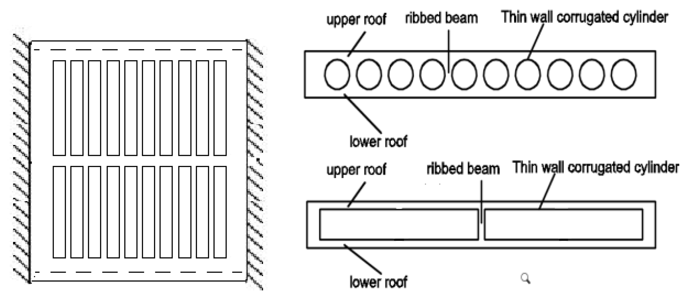
Thin-walled corrugated cylinders were fixed in a specific order in a slab that was placed inside a box mold. The hollow slab set by corrugated tubes was formed once the concrete had been poured into the slab. The slab system was composed of a slab made of concrete rib, thin-walled corrugated cylinders, and up-and-down flanges, as shown in Figure 1.
Figure 1.
Schematic diagram of hollow slab set by corrugated tubes.
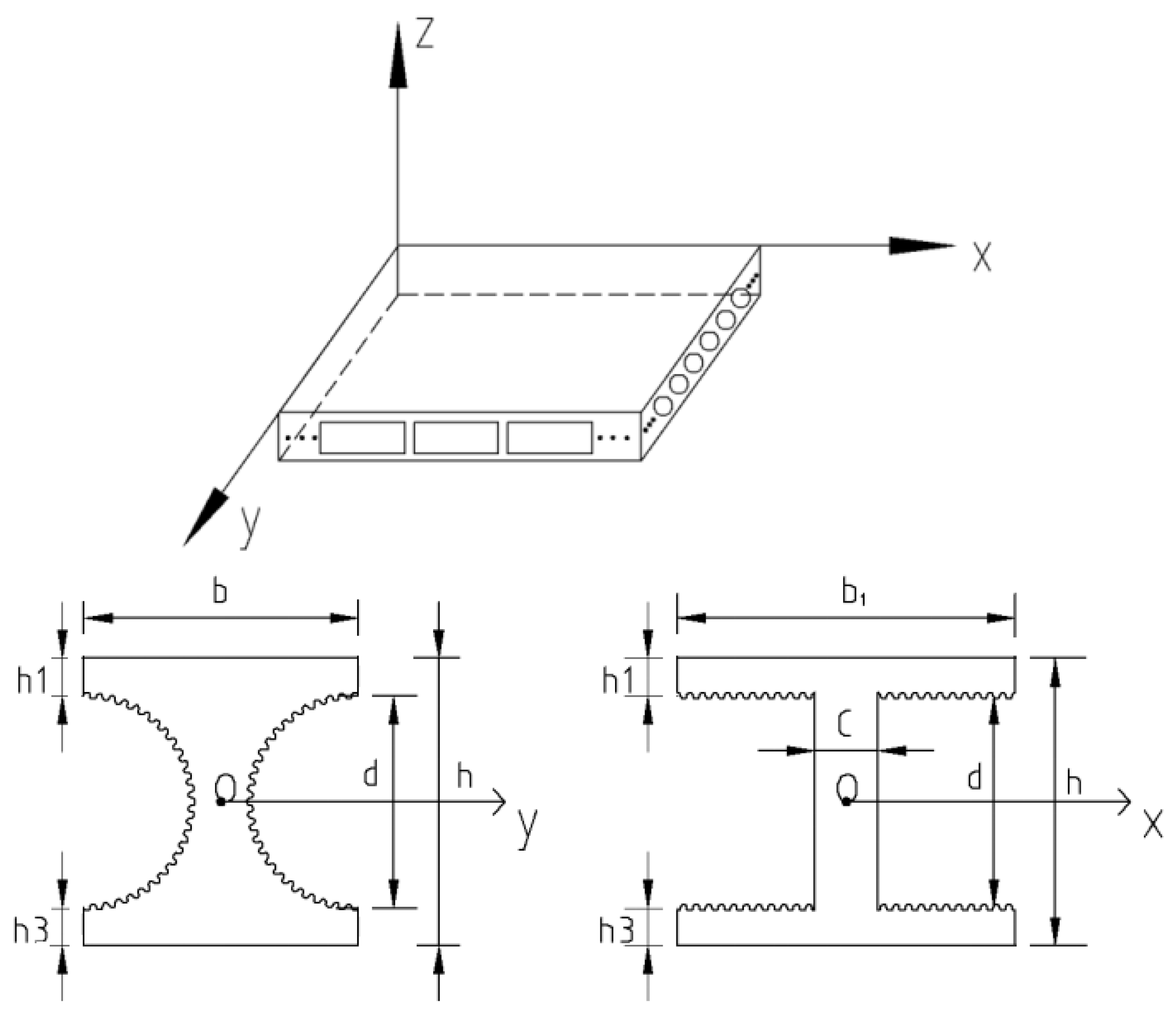
Based on the characteristics of this structure, we used Cartesian coordinates to establish its position, as shown in Figure 2. The length, thickness, and height of the slab were , , and , respectively. The cure of the thin-walled corrugated cylinder is the sine arc. Its length and height are and , respectively, and the distance between the cylinder and the up-and-down flanges are and , respectively. The X- and Y-axes could then be simplified into a cross-section of I-shaped steel set at the same distance. and are the elasticities of concrete and steel, and are their shear moduli, and are their Poisson’s ratios, and and are the moments of inertia of their cross-sections, respectively.
Figure 2.
Geometric model of the hollow slab.
3. Theory of Computation
3.1. Stiffness Formula
According to the theory of the stiffness of a hollow floor with corrugated cylinders under the anisotropic coupling of the material and the structure [2], the overall stiffness of the hollow pipe of the slab, set using corrugated tubes under the coupling of the anisotropies of the material and structure, is , and the values of flexural stiffness parallel and vertical to it are and , respectively, as shown in Formulas (1)–(3).
- (1)
- Vertical flexural stiffness of the hollow pipe
is the reduced factor of the anisotropic material along the Y-axis, which is , and is the simplified ripple coefficient along the Y-axis, and .
- (2)
- Parallel flexural stiffness of the hollow pipe
is the reduced factor of the anisotropic material along the X-axis, which is . The coefficients of conversion of the flange, web, and rectangular plate are and , respectively, where and . The simplified ripple coefficient along the Y-axis is , and .
- (3)
- Overall stiffness of hollow slab
and are the moments of inertia of the sections containing ribs with respect to their resistance to torsion, is the simplified coefficient on the whole plate, , and is the simplified ripple coefficient of the plate, .
3.2. Theoretical Formula of Deflection
To simplify the calculations, the thin plate can be considered to be two-dimensional. Moreover, we make three reasonable assumptions when analyzing the fields of stress and strain on the slab set using corrugated tubes. First, the normal strain perpendicular to the middle plate is zero. Second, we do not need to consider the normal stress and shear stress perpendicular to the middle plate when calculating the component of strain. Third, when the thin plate bends, there is no displacement at any point on the middle plate.
When we ignore shearing, the elastic differential equation of the orthotropic plate can be given by Formula (4):
where , , and are the values of elastic flexural rigidity along the main directions, and , , and .
As the hollow slab is simply supported by fixed constraints on opposite sides, its boundary conditions are as follows:
The solution to the differential equation of deflection derived from expansion using a triple trigonometric series is more sophisticated than that obtained from a single triangular series and has a much higher rate of convergence. We use Levy’s method to expand the deflection of the slab due to load using the Fourier series and obtain Formulas (6) and (7). The curve of the elastic differential equation, shown in Formula (8), can then be obtained by combining Formulas (6) and (7) with Formula (4), where this satisfies the boundary conditions of and .
Because of the varying stiffness of the hollow slab, an analytical solution for it is complex. We use the equation of its characteristic state to determine its deflection and consider for the sake of simplicity. Its deflection involves the constants A, B, C, and D, and , , , and .
- (1)
- When , the characteristic equation has four unequal real solutions: and . The deflection of the hollow slab can then be given as
- (2)
- When , the characteristic equation has four real solutions that are equal to one another: . The deflection of the hollow slab in this case is
- (3)
- When , the characteristic equation has two pairs of complex roots: and . The deflection of the hollow slab in this case is as follows:
To ensure that the thin plate under a fixed support is symmetric along the Y-axis, and is parallel to the principal elastic axis and the boundary, the solution for it must be an even function about the Y-axis.
When the odd term is neglected and the two curves are simplified, the deflection of the hollow slab is as follows:
When the condition of simply supported and fixed constraints on opposite sides is inserted into Formulas (5) and (12)–(14), the values of the constants A, B, C, and D can be calculated. Then, the deflection of the hollow slab set using thin-walled corrugated tubes on simply supported and fixed constraints on opposite sides under an even load is as shown below, where , , , , and .
- (1)
- When , the deflection of the slab is as follows:
- (2)
- When , the deflection of the slab is as follows:
- (3)
- When , the deflection of the slab is as follows:
4. Mechanical Model, Theoretical Formula, and Simulations
4.1. Mechanical Model
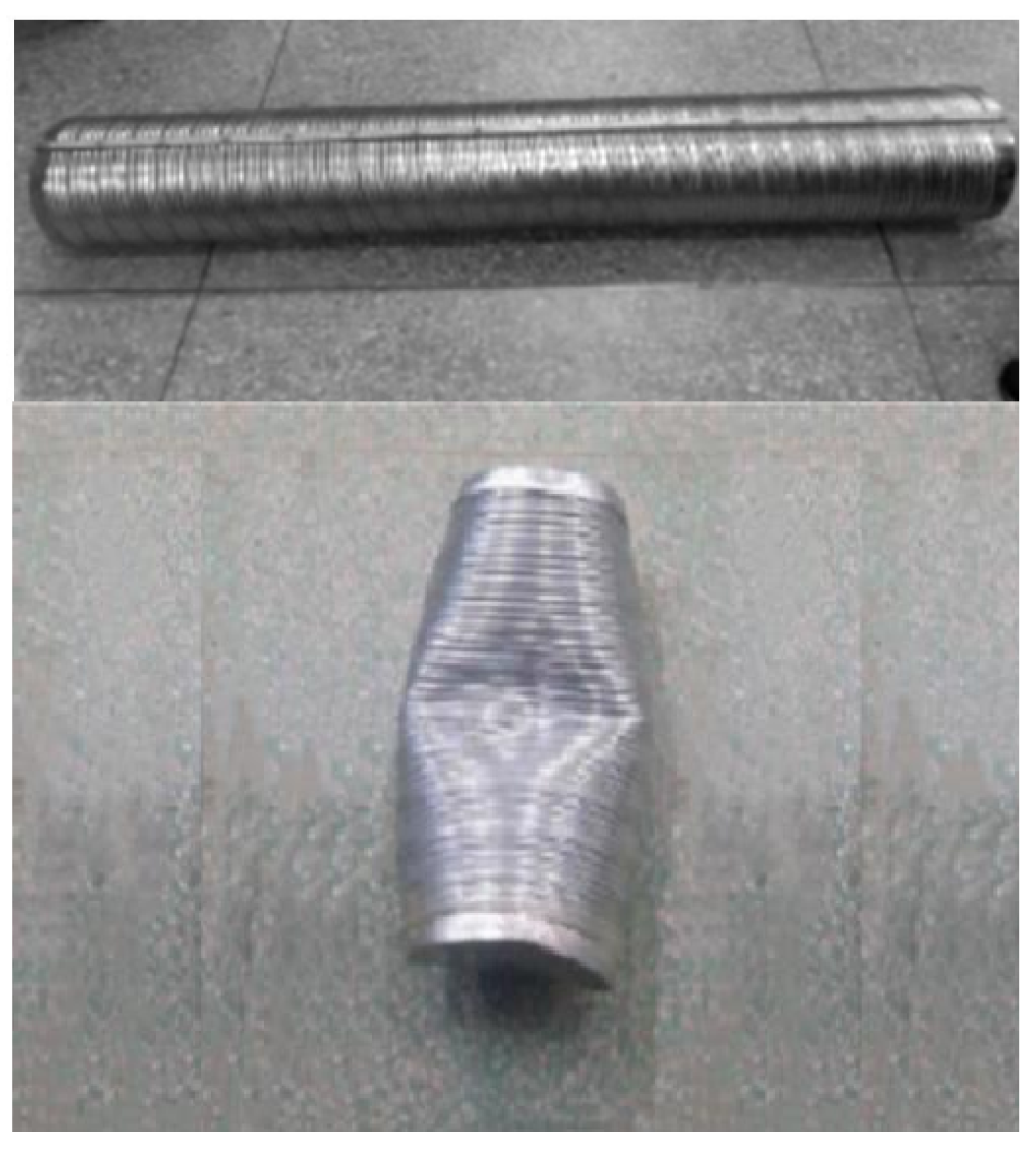
According to Eurocode 2 and European standard EN 1168 [21], Figure 3 shows that we considered a hollow slab, set using thin-walled corrugated tubes, with dimensions of for our mechanical model. We set 114 thin-walled corrugated tubes, each with a diameter and length of and , respectively, in the slab. Steel with a hollowness ratio of 11.3% was set at the bottom of the slab by way of . According to the Manufacturer’s Production Data Manual, the elastic moduli of steel and concrete in the model were and , and their Poisson’s ratios were and , respectively. We can obtain the elastic modulus, Poisson’s ratio, and yield strength from a uniaxial compression test on a corrugated tube. Figure 4 shows the uniaxial compression test on a corrugated tube. The mechanical properties of concrete, steel, and the corrugated tube are shown in Table 1. The hollow slab was subjected to loads of , , , and .
Figure 3.
Geometric model of hollow slab set using thin-walled corrugated tubes.
Figure 4.
Uniaxial compression test on corrugated tube.

Table 1.
Mechanical properties of concrete, steel, and corrugated tubes.
4.2. Theoretical Results
Based on the formula for the stiffness of the hollow slab that was set using corrugated tubes under the coupled anisotropies of the material and the structure, the values of stiffness along the principal axes , , and were, respectively, , , and , which satisfies the condition . The deflections of the hollow slab under even loads of , , , and were calculated based on its rigidity.
4.3. Results of Finite Element Model
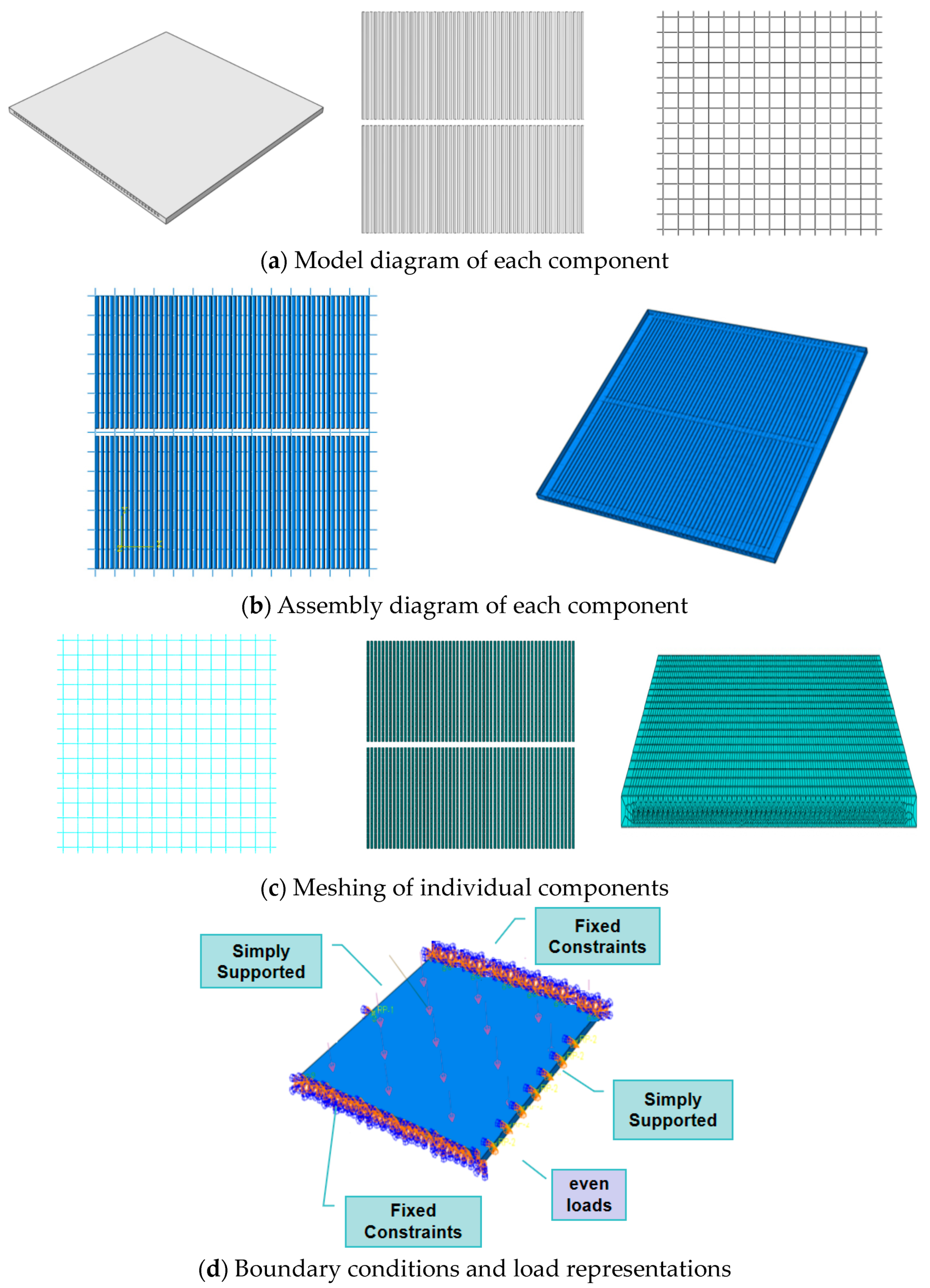
We used the finite element software ABAQUS6.14-2 to analyze the mechanical properties of the hollow slab. Firstly, we built the geometric model, and the steel set in the slab was also reinforced by an assembled constraint. Then, the steel was assembled to form a steel mesh and embedded in the concrete slab. Secondly, the parameters of the materials were assigned to the model shown in Table 1. Thirdly, during the simulations, we separately set up models of concrete, steel, and corrugated tubes through adaptive meshing. We used the solid, 3D, eight-node reduced integral element (C3D8R) for concrete, the type, angle of expansion, and eccentricity of which were C30, 30, and 0.1, respectively. We used the solid, 3D, two-node truss element for steel and applied the tie constraint between the corrugated tubes and the concrete plate. The model included concrete, steel, and corrugated tubes, so contact analysis was applied to control the displacement. In other cases, when the cohesion and slippage between concrete, steel, and corrugated tubes are not considered, the displacement between them must be harmonious.
Because both the element shapes of corrugated cylinders and concrete slabs are quadrilaterals, the structured meshing will be accomplished with a neutral axis algorithm and advanced algorithm during structured meshing. A model diagram of the deflection of a hollow slab set by a thin-walled corrugated tube on simply supported and fixed constraints on opposite sides under even loads is shown in Figure 5 using ABAQUS6.14-2. Fourthly, both the linear displacement and angle of rotation on the opposite side were zero in the model, as was the linear displacement. The nodal points between the concrete slab and the corrugated tube needed to correspond to each other to enable the analysis of contact between the concrete, steel, and the corrugated tube, while the bond-slipping effect could not be considered. The parameters of the materials are shown in Table 1. Fifthly, the even load by some steps was loaded into the model. Finally, Figure 6 shows the results of the modeled deflections of the hollow slab under even loads of , , , and by creating and submitting the job. The deflection data are shown in Table 2.

Figure 5.
Model diagram of ABAQUS 6.14-2.
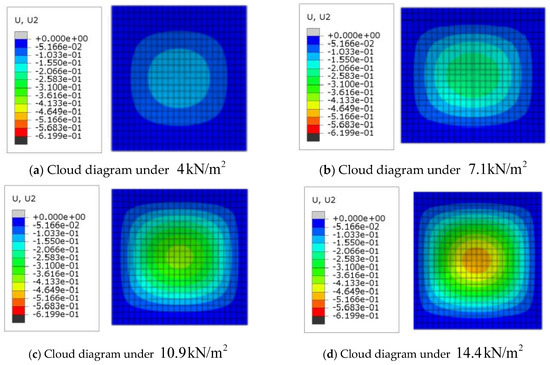
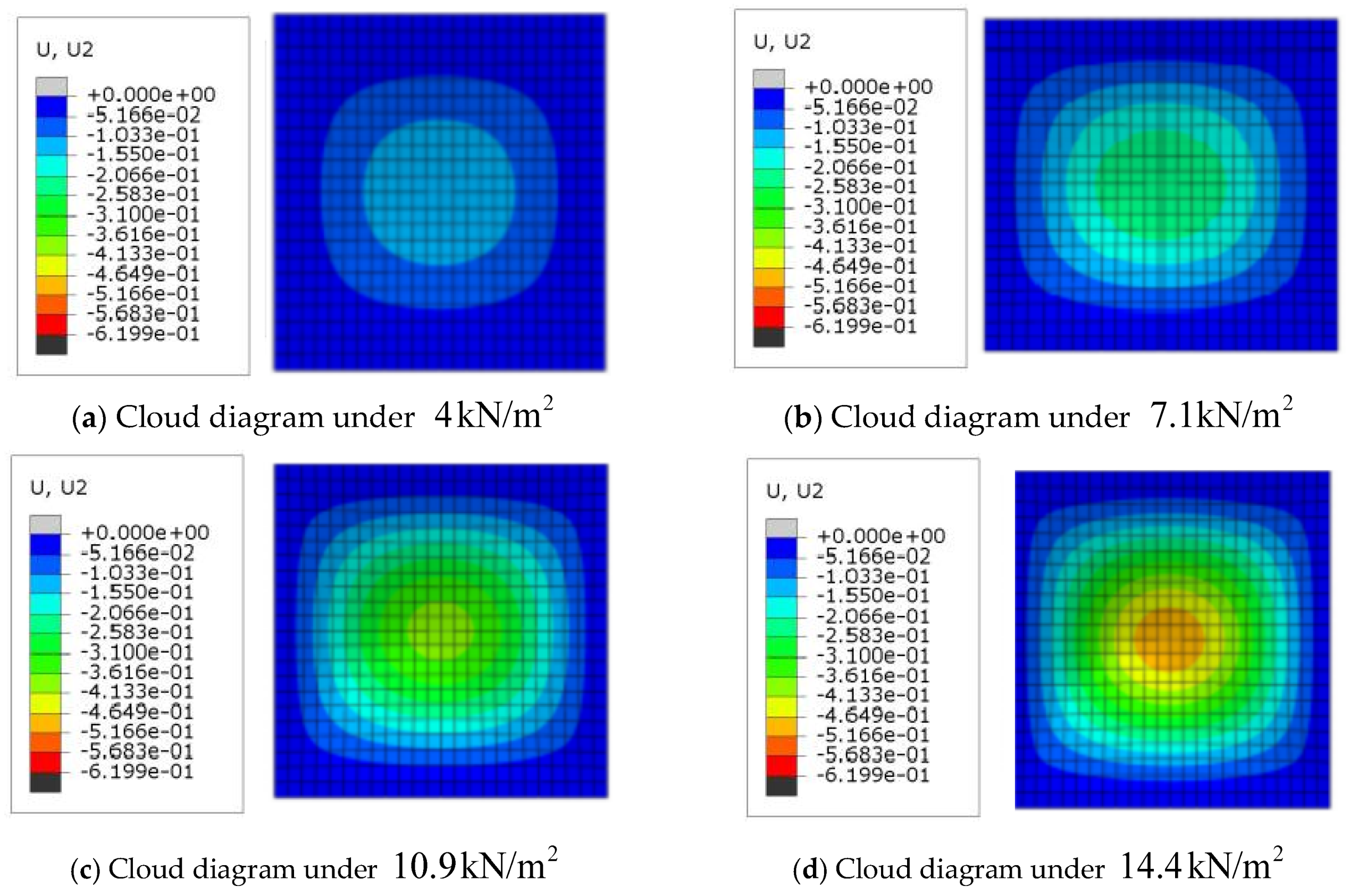
Figure 6.
Cloud diagram of the displacement of the slab under all different loads on Axial Z.
Table 2.
Comparison of the results of the theoretical calculation, loading test, and numerical analysis.
4.4. Test Results
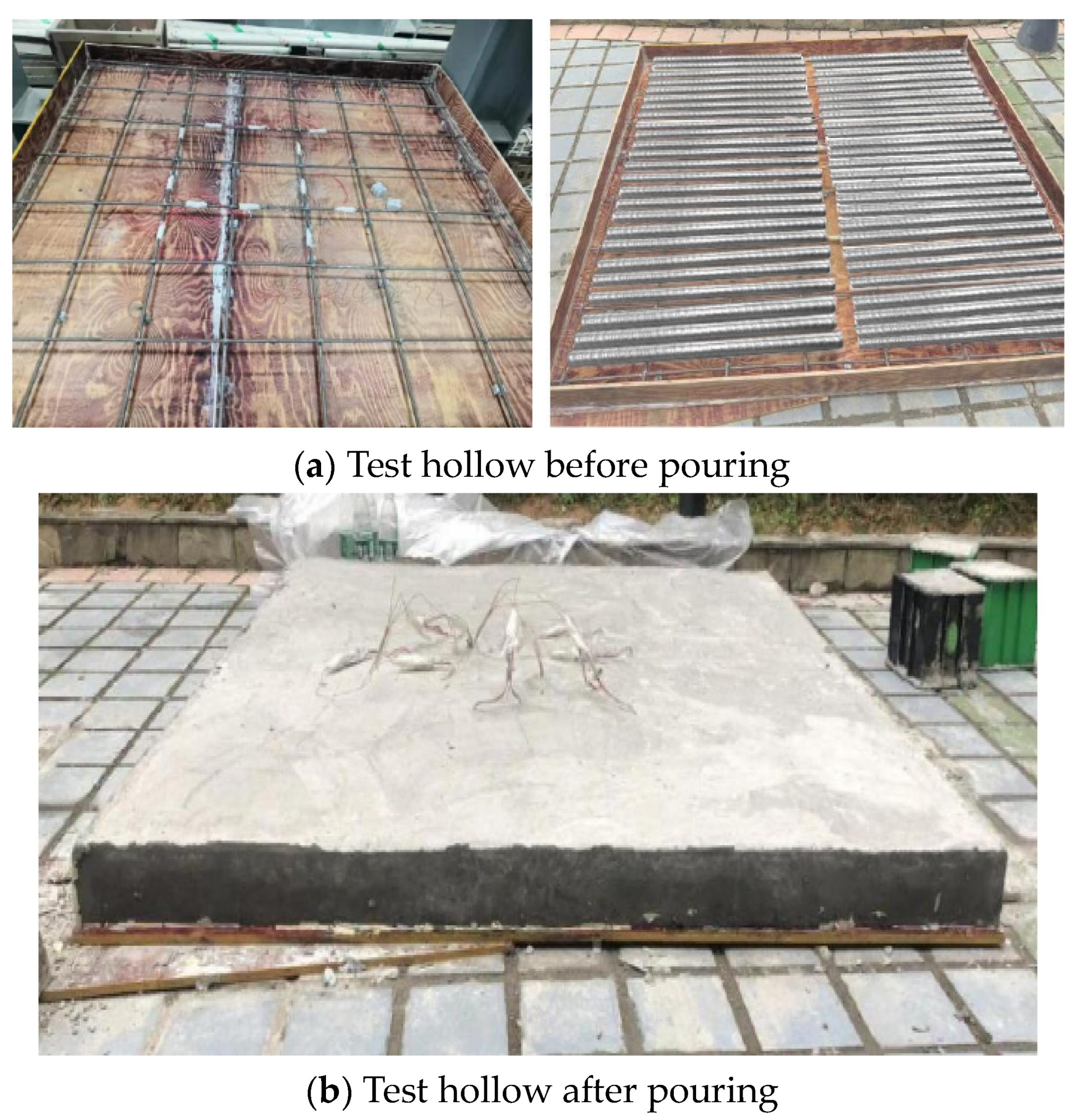
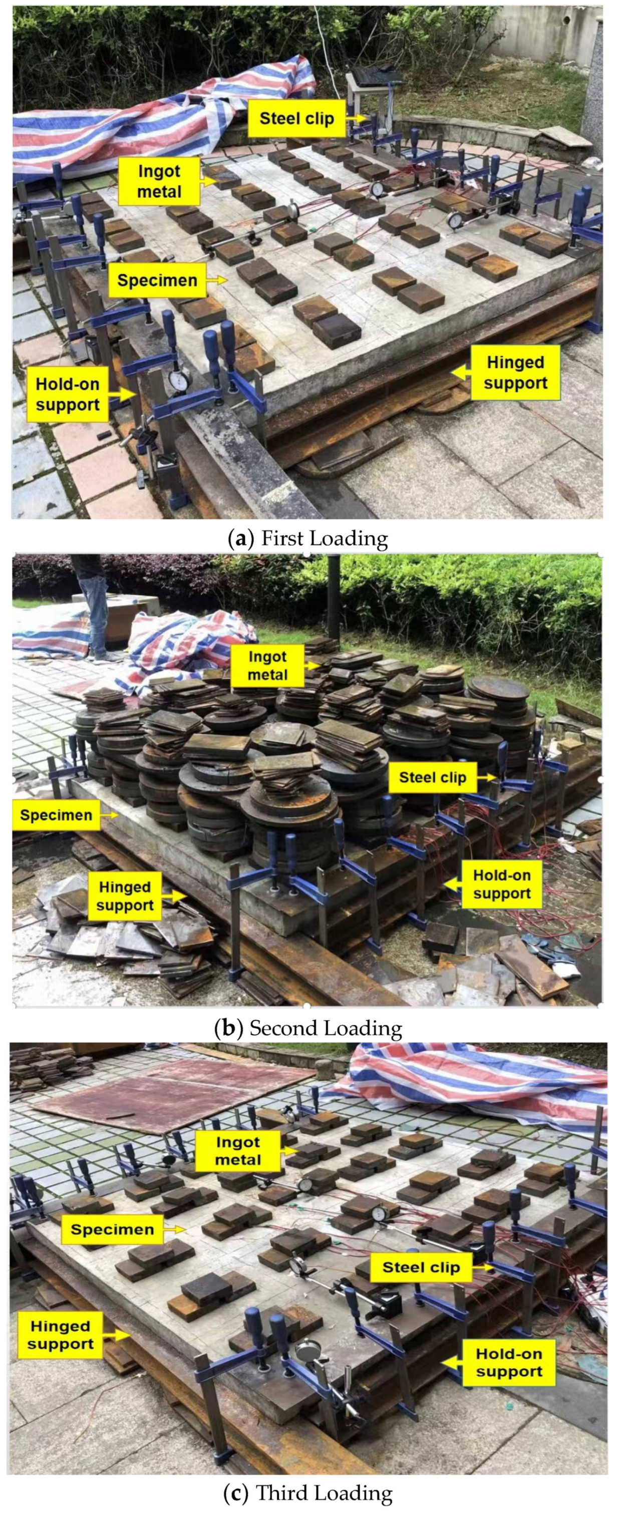
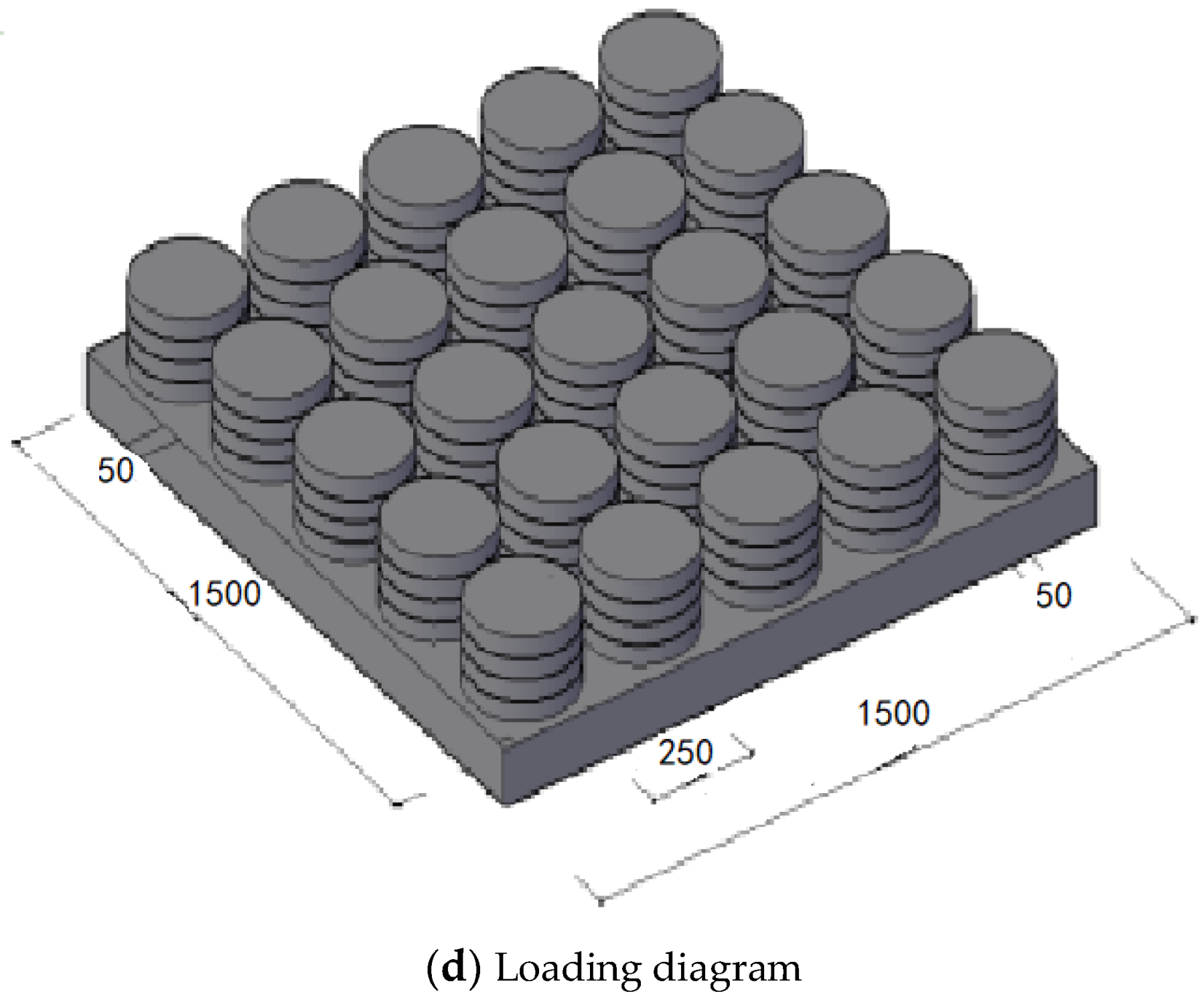
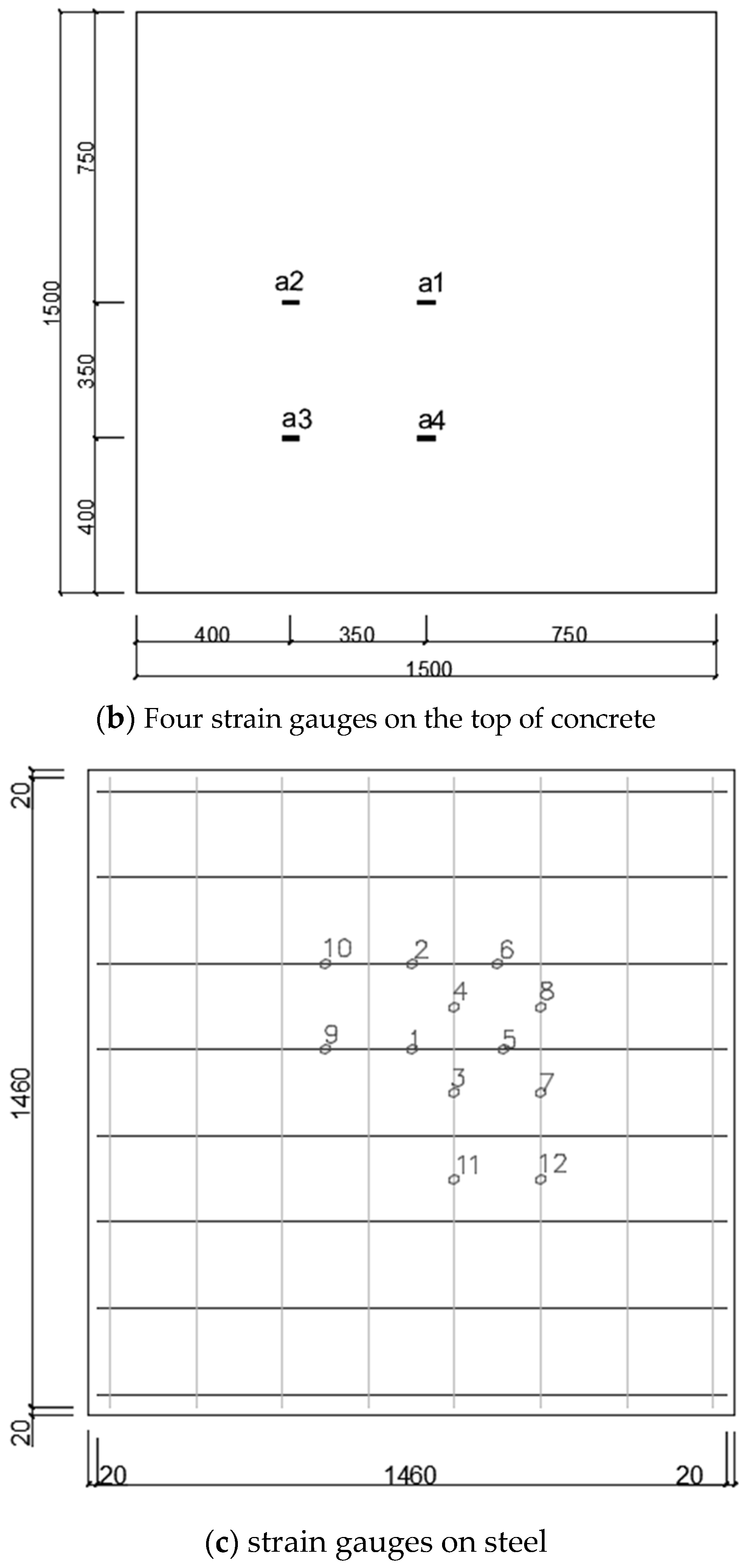
We followed the Eurocode 2 and European standard EN 1168 [21] standards for testing concrete structures. We formed a set of three hollow slabs, supported by thin-walled corrugated tubes, with dimensions of , as shown in Figure 7. Given that the slab was fixed to shaped steel by 16 heavy-strength super large F clips on the opposite side, the constraints may be simplified to the fixed one. In the standard, we put the regular shape block, less than , on the hollow slab regularly four times, as shown in Figure 8. Figure 9 shows that six dial indicators and eight strain gauges (four are on the top, corresponding to others below) were installed on the surface of the hollow slab to measure its deformation on the simply supported and fixed constraints on opposite sides.
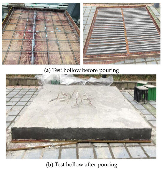
Figure 7.
Model-making process of hollow slab set by thin-walled corrugated tube.
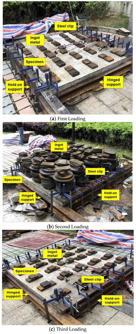
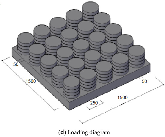
Figure 8.
Test module of hollow slab set using thin-walled corrugated tubes and modeling of the load.
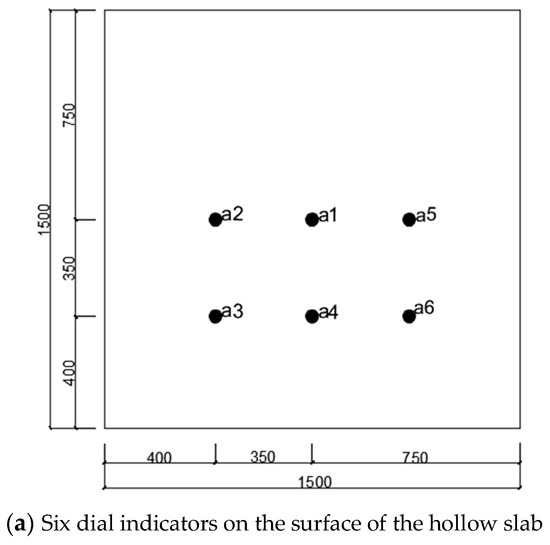
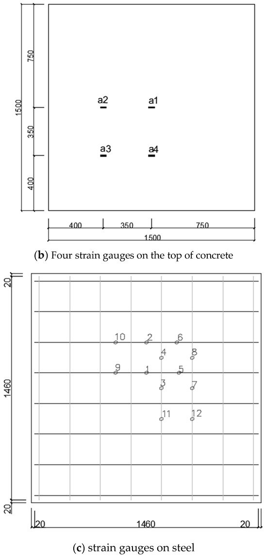
Figure 9.
Layout of dial indicators and strain gauges.
4.5. Analysis of Results
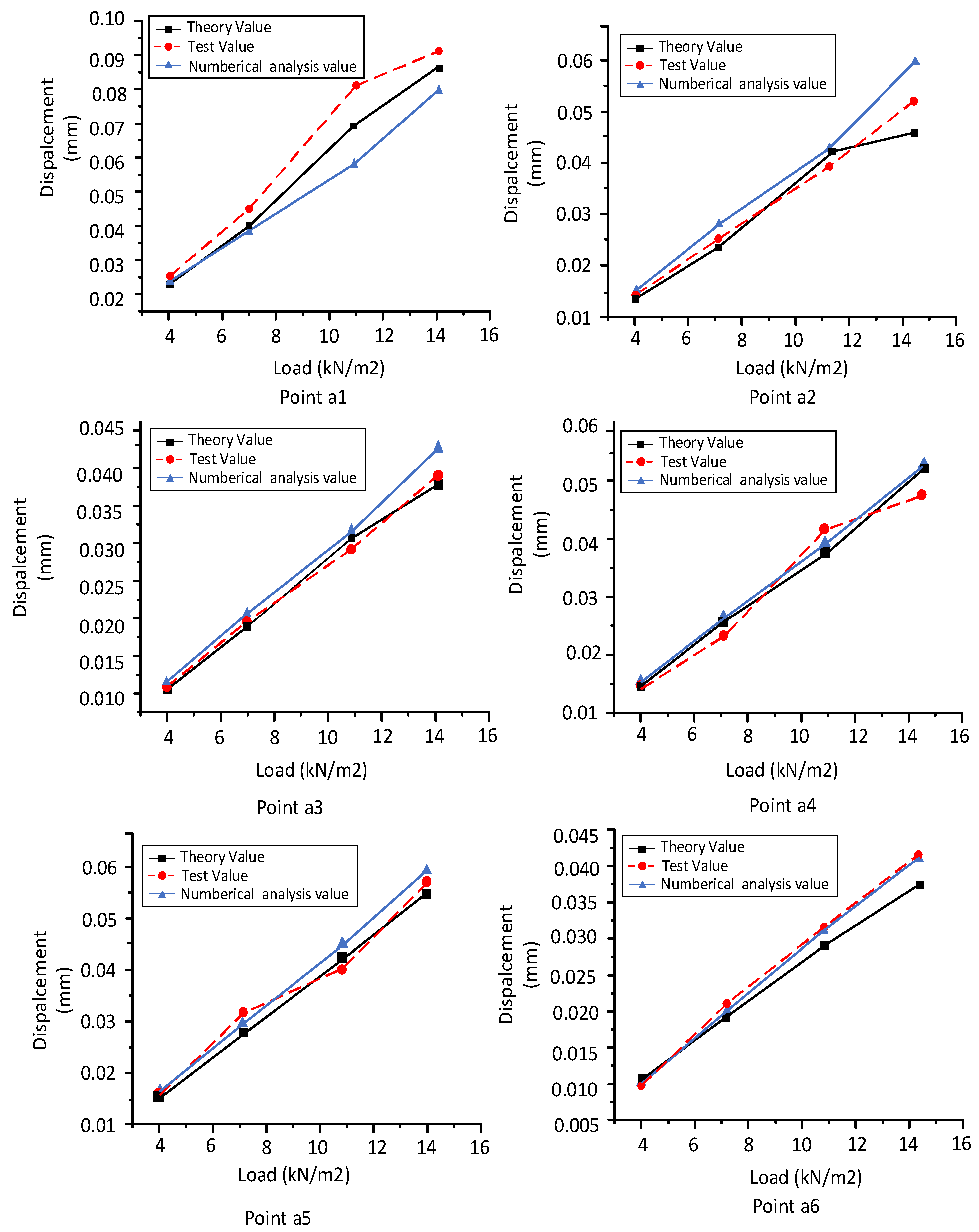
Table 2 shows the deflection results of the hollow slab under an even load that were obtained using theoretical calculations, finite element simulations, and loading tests, while Figure 10 compares them. It is clear that the deflection in the middle of the slab was large and that along its edges, it was zero, while the largest deflection was recorded at point a1. Table 2 shows that the results of the theoretical calculations deviated from those of the loading test by 9.09% at point a6.
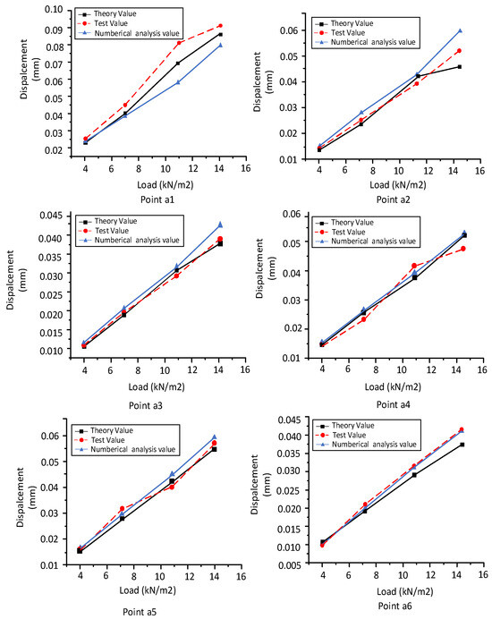
Figure 10.
Comparison of the results of the theoretical calculation, loading test, and numerical analysis.
5. Discussion
From Figure 6, as the load increases, the deflection of the hollow slab set using corrugated tubes also increases. It is symmetrical along the center-line of the slab for the X- and Y-axis. The deflection in the middle is larger than the ones on the edge, and the deflection is zero on the fixed constraints. It is clear that the deflection in the middle of the slab was large and that along its edges, it was zero, while the largest deflection was recorded at point a1. It is verified that the displacement of the slab under all different loads on axial Z conformed to the general law, and is less than the solid plate. Under , the slab is not broken and is in the elastic stage.
Within the bearing limit state, the curve chart on deflection and load is linear. When the load becomes larger, it is better to fit the theoretical prediction, the outcomes of the static loading test, and the finite element model. The results showed that while the maximum deformation occurred at point a1 in the middle of the slab, the maximum errors among the results of the theoretical formula, static loading tests, and the finite element model occurred at point a2. The maximum and minimum errors between the results of the theoretical prediction and the outcomes of the static loading test were 9.09% and 0%, while those between the results of the theoretical prediction and the finite element model were 8.92% and 1.19%. In addition to the small deflection value and inexact properties of steel and concrete, there are many other reasons for the errors. For example, uniform mixing with cement causes concrete to be dense. Heavy strength super large F clips and I-shaped steels were applied to the fixed hollow slab in this manuscript. Although the stiffness of heavy strength super large F clips and I-shaped steels is large, it differs from fixed constraints under ideal conditions for still exiting deformation. Also, in order to carry even loading, the way that the steel plates were laid on the hollow slab in this paper is different from an even load under ideal conditions. In a word, by analyzing the results, the proposed hollow slab, set using thin-walled corrugated tubes, can be used in a variety of engineering designs.
6. Conclusions
Hollow slabs have a large hanging area, crack easily, have bad sound insulation and poor seismic resistance, etc.; therefore, fewer and fewer hollow slabs are being used in large-span structures. Here, we propose a hollow floor with built-in corrugated pipes as filling material, which has the advantages of a lighter weight, higher stiffness, and lower cost than traditional floors. In this study, we used theoretical analysis, finite element modeling, and experiments to examine the law of deformation of a hollow slab set using thin-walled corrugated tubes on simply supported and fixed constraints on opposite sides. The main conclusions are as follows:
- (1)
- We developed a new form of stiffness for the hollow slab by coupling the anisotropies of the material and the structure.
- (2)
- We used the new concept of stiffness of the hollow slab to derive the formula for its deflection under an even load.
- (3)
- We conducted loading tests on a hollow slab with dimensions of using even loads of , , , and .
- (4)
- We used Eurocode 2 and European standard EN 1168 [21] for concrete structures to test three sets of hollow slabs with corrugated tubes supported by simple and fixed constraints on opposite sides. A comparison of the results with those of the theoretical formula at six reference points showed that the ideal experimental results were obtained, with a maximum error of 9.09%, at point in the middle of the slab under a load of .
- (5)
- We used the finite element software ABAQUS 6.14-2to model the deflection of the hollow slab. A comparison of the results of the simulations with those of the theoretical formula showed that they agreed well with each other, with the largest error of 8.92% under a load of .
- (6)
- We analyzed the results of the static loading test, the theoretical formula, and the finite element model and found that hollow slab is in the elastic stage, and hollow floors are widely used in structures with a large span that bear a large load. The theory about the deflection of a hollow slab set by thin-walled corrugated tubes on simply supported and fixed constraints on opposite sides is useful for designing them in engineering.
7. Patents
There are two patents resulting from the work reported in this manuscript, which are “A Method for Mechanical Analysis and Calculation of Hollow Floors with Embedded Thin Wall Corrugated Cylinders” and “A method for calculating the stiffness of hollow floor slabs with built-in corrugated cylinders”.
Author Contributions
Conceptualization, F.Y. and Y.L.; methodology, F.Y. and J.L.; validation, F.Y. and Q.H.; resources, Y.L. and J.L.; writing—original draft preparation, Q.H. and J.L. All authors have read and agreed to the published version of the manuscript.
Funding
This research was supported by the Joint Funds of the Zhejiang Provincial Natural Science Foundation of China (LZY24E050002). Quzhou Science and Technology Planning Project (2023K231). Quzhou University’s research start-up funding support project (BSYJ202208, BSYJ202318).
Data Availability Statement
The data presented in this study are available in the article.
Conflicts of Interest
The authors declare no conflict of interest.
References
- Li, C.; Sun, Q.; Liu, Y. Study on static load test of simply supported hollow slab bridge flexural strengthened with polyurethane-cement composite. Int. J. Struct. Integr. 2022, 13, 112–132. [Google Scholar] [CrossRef]
- Chung, J.H.; Choi, H.K.; Lee, S.C.; Choi, C.S. The Deflection of Donut Type Hollow Slab Considering Crack Behaviors. Key Eng. Mater. 2013, 577–578, 621–624. [Google Scholar] [CrossRef]
- Ibrahim, I.; Elliott, K.; Abdullah, R.; Kueh, A.; Sarbini, N. Experimental study on the shear behaviour of precast concrete hollow core slabs with concrete topping. Eng. Struct. 2016, 125, 80–90. [Google Scholar] [CrossRef]
- Liu, J.; Jia, Y.; Zhang, G.; Wang, J. Calculation on the flexural stiffness of the section of PC hollow slab beam in the life cycle. Int. J. Struct. Integr. 2018, 9, 241–254. [Google Scholar] [CrossRef]
- Yang, F.; Miao, Y.; Su, C.; Lv, H. Stiffness theory of hollow floor with corrugated cylinder under anisotropic coupling of material and structure. Sci. Technol. Eng. 2021, 21, 3237–3243. [Google Scholar]
- Pillai, U.S.; Sapru, K. Ultimate Strength of Cellular Flat Plate. J. Struct. Div. 1974, 100. [Google Scholar] [CrossRef]
- Pawar, J.A.; Patil, D.Y.; Vesmawala, R.G.; Dhake, P.D.; Nikam, J.S. Two-way flexural behavior of biaxial voided slab using cuboidal shape of void formers. Structures 2024, 62, 106175. [Google Scholar] [CrossRef]
- Wei, Y.; Wang, Z.; Xiang, J.; Qiang, S. The Development of New Type GFRP Hollow Panels. J. Phys. Conf. Ser. 2024, 2736, 012031. [Google Scholar] [CrossRef]
- Eisa, A.S.; Aboul-Nour, L.A.; El-Ghamry, A.; Zeleňáková, M.; Katunský, D. Flexural behavior of two-layer reinforced concrete slab with hollow cores. Adv. Mech. Eng. 2024, 16, 16878132231224940. [Google Scholar] [CrossRef]
- Sahoo, S.; Veerendar, C.; Prakash, S.S. Experimental and numerical studies on flexural behaviour of lightweight and sustainable precast fibre reinforced hollow core slabs. Constr. Build. Mater. 2023, 377, 131072. [Google Scholar] [CrossRef]
- Sahoo, S.; Veerendar, C.; Thammishetti, N.; Prakash, S.S. Experimental and numerical study on behaviour of fibre reinforced lightweight hollow core slabs under different flexure to shear ratios. Structures 2023, 50, 1264–1284. [Google Scholar] [CrossRef]
- Cui, W.; Liu, C.; Chen, Z.; Yin, W.; Liu, S. Influences of vertical joints on flexural performance of fabricated hollow cross-grid floor slabs. J. Southeast Univ. 2018, 48, 106–112. [Google Scholar]
- Mohsin, M.E.; Sadek, E.E. Beam Analog for Plate Elements. J. Struct. Div. 1976, 102, 125–145. [Google Scholar] [CrossRef]
- Yang, J.; Jin, L.; Wang, M.; Yang, C. Experimental study on bending behavior of cast in situ concrete hollow slab laying tube filler. J. Railw. Sci. Eng. 2008, 5, 28–32. [Google Scholar]
- Yang, J.; Wang, J.; Wang, M.; Pan, Y. Experimental research on mechanical behavior of the cast-in-situ rein-forced concrete hollow girderless floor under different load case. J. Railw. Sci. Eng. 2004, 1, 88–91. [Google Scholar]
- Lü, H.; Song, G.; Xie, B.; Fu, M. Mechanical properties of metal bellows. J. Nanchang Univ. 2016, 40, 138–139. [Google Scholar]
- Mark, J.; Zhang, H.; Huang, Y.; Xiao, J.; Duan, Y.; Zhang, J.; Cao, Y. Study and Application of Long Span Reinforced Concrete Vierendeel sandwich Plate. J. Build. Struct. 2000, 12, 16–23. [Google Scholar]
- Gu, L. Stress and Flexibility Analysis of The Anisotrophy Cast-In-Situ Concrete Floor System; Hefei University of Technology: Hefei, China, 2007. [Google Scholar]
- Yu, Z.; Xie, Q.; Liang, Z. Flexural Capacity of New Type of Assembly Ribbed Floor with Four-edge Simply Supported. J. Univ. Jinan 2020, 34, 124–130. [Google Scholar]
- Huang, C.; Wang, Z.; Deng, R.; Zhu, L. Study on Analogue Slab Method Considering Shear Deformation for Box-filler Hollow Floor. Eng. Mech. 2015, 32, 198–207. [Google Scholar]
- EN 1168; Precast Concrete Products–Hollow Core Slabs. European Committee for Standardization: Brussels, Belgium, 2011.
- El-Sayed, A.K.; Al-Negheimish, A.I.; Alhozaimy, A.M.; Al-Saawani, M.A. Evaluation of Web Shear Design Procedures for Precast Prestressed Hollow Core Slabs. Buildings 2022, 13, 23. [Google Scholar] [CrossRef]


Disclaimer/Publisher’s Note: The statements, opinions and data contained in all publications are solely those of the individual author(s) and contributor(s) and not of MDPI and/or the editor(s). MDPI and/or the editor(s) disclaim responsibility for any injury to people or property resulting from any ideas, methods, instructions or products referred to in the content. |
© 2024 by the authors. Licensee MDPI, Basel, Switzerland. This article is an open access article distributed under the terms and conditions of the Creative Commons Attribution (CC BY) license (https://creativecommons.org/licenses/by/4.0/).