Article

Quantitative Study on the Impact of Surcharge on Nearby Foundations

1
CCCC Third Harbor Consultants Co., Ltd., Shanghai 200032, China
2
Key Laboratory of Geotechnical and Underground Engineering of the Ministry of Education and Department of Geotechnical Engineering, Tongji University, Shanghai 200092, China
*
Author to whom correspondence should be addressed.
Buildings 2024, 14(6), 1596; https://doi.org/10.3390/buildings14061596
Submission received: 27 March 2024 / Revised: 22 April 2024 / Accepted: 6 May 2024 / Published: 31 May 2024
(This article belongs to the Section Building Structures)

Abstract

:
Situated within the context of a soft ground foundation at an iron ore mining site, this study investigates the impact of substantial surcharges on the settlement of such foundations and the adjacent infrastructure. By employing the finite-difference numerical software FLAC3D 6.0, a series of three-dimensional simulations were conducted to assess the stress response and deformation of gallery pile foundations, shallow foundations, and mine shed pile foundations to step loading. This study integrates the analysis of soil strength augmentation under considerable stress and its attenuation characteristics under significant deformation. Various reinforcement measures, such as the implementation of stone columns, prefabricated vertical drain, and surcharge preloading techniques, were examined for their capacity to consolidate the foundation, reduce settlement, and mitigate impacts on adjacent structures. The results reveal that horizontal displacements in the pile and shallow foundations escalate progressively with additional surcharge throughout the operational period. The most pronounced horizontal deviation in the pile foundations is observed at the juncture between sand and silt strata. Stone columns act effectively as a barrier to the sliding surface, consequently reducing the influence of surcharge on the movement of the foundation.

1. Introduction

There are a large number of weak and poor foundations in China, especially in the coastal delta areas, mostly silt, silty soils, etc. These soils have obvious characteristics, such as high water content [1], high compressibility [2], low water permeability, and high variability [3,4]. Therefore, engineering construction on the above foundations, especially under the action of a large-area surcharge, will inevitably cause serious impacts on the adjacent foundations [5]. So firstly, it is necessary to carry out reinforcement to meet the settlement requirements raised by the specifications. A composite foundation is a common form of soft soil reinforcement, generally using partial soil replacement, stone columns to reinforce soil, or prefabricated vertical drain to accelerate the consolidation of soil, aiming to improve the bearing capacity and reduce the settlement deformation of the foundation.
Previous studies have endeavored to investigate the intrinsic mechanism of the stone columns that influence the refinement effect of soft foundations. Shao et al. [6] investigated the effect of stone columns and geosynthetics on the deformation and stability of embankments on soft soil foundations, and the results showed that stone columns reinforcement reduced settlement to a greater extent. Zhang and Xiao [7] concluded that the migration of clay particles would cause blockage of stone columns, which is unfavorable to the consolidation of soft soil foundations, so they discussed the settlement and consolidation characteristics of soft soil foundations reinforced by stone columns. Chen et al. [8] assessed the overall shear strength of composite foundations through on-site monitoring and numerical simulation taking the artificial island of the Hong Kong–Zhuhai–Macao Bridge as an example. Han et al. [9] discussed the applicability of vibrated stone columns in underwater super-soft ground based on field tests and concluded that the amount of filler is the most important factor for the densification of composite foundations. Tao Yang et al. [10] compared the reinforcement effect of the two treatments on stone columns and prefabricated vertical drain for soft ground, and the results proved that the prefabricated vertical drain is beneficial to accelerate the consolidation of soft ground, while the stone columns can control and reduce the horizontal deflection of the foundation. Dade Zhang et al. [11], through a failure case study on soft ground reinforced by prefabricated vertical drain, proposed that the short-term reinforcing effect of geotextile should be considered on the stability of embankment, and gave emergency disposal measures.
The abovementioned research focused on modeling or field trials; few efforts have been devoted to theoretical innovations. To further understand the concept of soil consolidation and the influence of large-scale surcharge on adjacent pile foundations, Chen et al. [12] incorporated the concept of consolidation degree into the settlement deformation of soft ground foundation and fitted the settlement calculation formula to establish a relationship between the compression coefficient and elastic modulus of composite foundations. Zhang et al. [13] investigated the law of settlement deformation of composite foundations under surcharge based on soft ground foundations reinforced by stone columns test. Jiang et al. [14] combined the two-stage analysis method to establish differential equations of the deformation of pile foundations. They obtained the time-domain solution of the horizontal displacement of the pile foundation considering the shear effect and the thickness of the pile–soil shear layer, which can well explain the influence of the excavation of soft ground foundation pits on the adjacent pile foundations. Relying on a soft ground treatment project in Shanghai, Zhan et al. [15] concluded that the height of the fill and the thickness of the soft soil layer affect the safety distance of the pile foundations of adjacent buildings, which reduces the role of the foundations in the horizontal offset of the adjacent buildings. Because there is a relatively large level of statistical scattering in soil and foundations, it is of great importance to conduct reliability analysis on shallow foundations to create instructions for construction. Kamiński and Świta [16,17] raised the generalized stochastic finite element method in elastic stability problems and conducted a stochastic perturbation-based finite element method analysis of the stability and reliability of the underground waste container.
However, few studies mentioned above address the computation of large three-dimensional numerical models in complex environments, providing limited consideration to the foundation types of adjacent buildings, and they rarely investigate the internal force distribution within pile foundations. Therefore, this work employs the Hardening Soil Model (HS) to accurately characterize the deformation and strength characteristics of soft soil foundations under loading and unloading conditions. Furthermore, the stress response of adjacent pile foundations to large-scale surcharge is significantly discussed.
Relying on an iron ore base in a sea area of Ningbo, this paper considers the strength hardening and softening characteristics of soil under high-stress conditions and large-deformation conditions, respectively. This paper establishes a numerical model to assess the impact of large-scale surcharge of pile foundations, the shallow foundations of the gallery, and the pile foundations of the mine shed, aiming to reduce the post-industrial settlement of foundations and the impact of the surcharge on the foundations of the adjacent buildings.

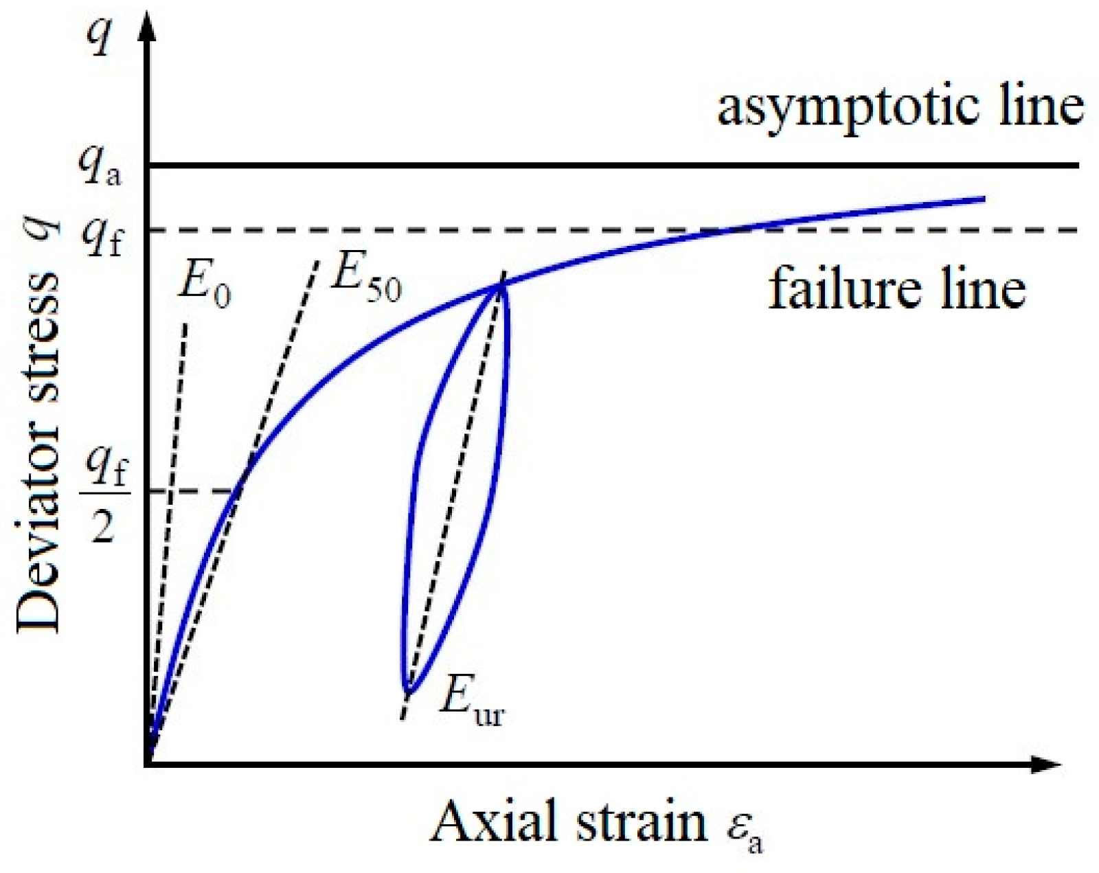
2. Hardening Soil Constitutive Model

The key issue in numerical analysis involves selecting appropriate constitutive models and computational parameters. The Hardening Soil Model (HS) effectively captures the hardening behavior of soft clay, differentiating between the loading and unloading phases. This makes it well suited for simulating the impact of large-scale surcharges on adjacent pile foundations in soft terrain. In this study, we employ the Hardening Soil Model to accurately depict the deformation and strength characteristics of soft soil foundations under the loading and unloading conditions associated with mine heaping. Within this model, the elastic part is usually represented by a linear elastic model, while the plastic part involves the plastic flow law and hardening law of the soil, with a total of eleven parameters, including cohesion c , internal friction angle ϕ , dilatancy angle ψ , reference secant stiffness from drained triaxial test E 50 r e f , reference tangent stiffness for oedometer primary loading E o e d r e f , exponential power m ; reference unloading/reloading stiffness E u r r e f , unloading/reloading Poisson’s ratio υ u r , reference stress p r e f , failure ratio R f , and coefficient of earth pressure at rest K 0 . According to the correlation of the common correlation modulus, i.e., E 50 r e f = E u r r e f / 3 , E o e d r e f = E 50 r e f / 1.25 , the values of E 50 r e f and E o e d r e f are obtained. Figure 1 shows the stress–strain relationship of the HS model.

3. Numerical Analysis Model

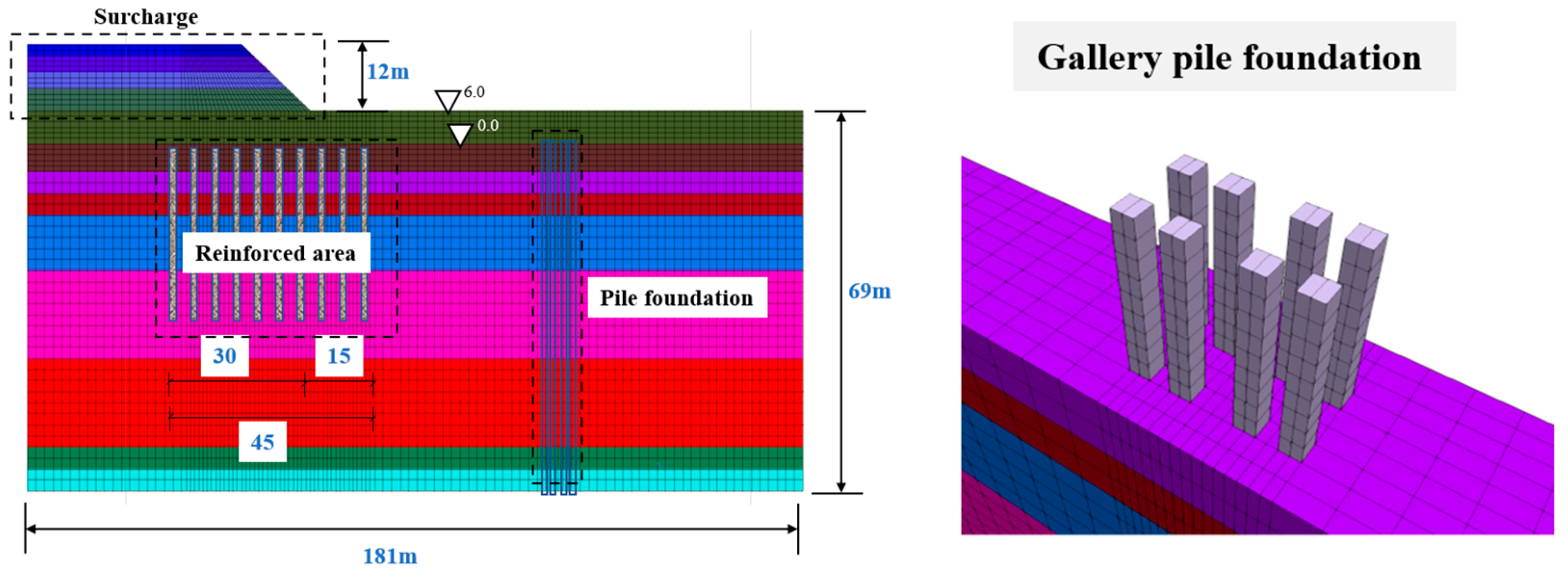
3.1. Calculation Model and Parameters

The pile foundations and shallow foundations of the gallery are located in the same stratigraphic environment, and the surface of the original soil is 5.1 m below the absolute elevation of 0 m in Figure 2 and Figure 3. The foundation soil from top to bottom is as follows: ②1 muddy, thickness of 4 m; ③1 muddy silty clay, with a thickness of 4 m; ③2-1 muddy clay, thickness of 10 m; ③2-2 silty clay, thickness of 15 m; ④2 silty clay, thickness of 17 m; ⑤1 silty clay, thickness of 2.9 m; ⑤3 silt, thickness of 3.5 m. Sand lies from an absolute elevation of 0 m to the original soil surface (absolute elevation −5.1 m), and backfill stone lies from an absolute elevation of 0 m to 5.8 m in the figure. The specific layering and physical–mechanical parameters of the soil are shown in Table 1.
The pile foundation part was simplified as reinforced foundation treatment, and the backfill sand part used the Mohr–Coulomb Law as a constitutive model. An elastic constitutive model was adopted for the cast-in-place pile, shown in Table 2. The model was fixed at the bottom, with normal constraints all around, and free at the top surface. The model was set up with impermeable boundaries around the periphery and at the bottom surface. The groundwater level is stable at −2.0 m during the construction period; the groundwater level is considered to be +4.3 m during the use period. The length of the stone columns is 30 m, with a replacement rate of 20%. The length of the stone columns is 60 m.
As shown in Figure 4, the model has a total length of 181 m and a width of 8 m, with a fixed bottom, normal constraints around the perimeter, and a free top surface, and the model is set up with impervious boundaries around the perimeter and the bottom surface. The height of the heaping mine is 12 m, and the width of the gravel pile reinforcement under the heaping mine is 45 m. The length of the gravel piles under the heaping mine is 30 m, and the length of the gravel piles in the area of building pile foundations is 35 m, both of which adopt the Mohr–Coulomb isotropic model with a replacement ratio of 25%. Four steel piles are set up under each bearing, which are steel piles with a diameter of 800 mm, a wall thickness of 12 mm, a length of 50 m, and a top elevation of 4.3 m, adopting the elastic isotropic model. The groundwater level is considered to be stable at −2.0 m during the construction period and +4.3 m during the service period.
The surface of the original soil is 3.2 m below the absolute elevation of 0 m. The foundation soil from top to bottom is as follows: ②1 muddy, thickness of 10.5 m; ③1 muddy silty clay, thickness of 8 m; ③2-1 muddy clay, thickness of 6 m; ③2-2 muddy clay, thickness of 8 m; ④2 silty clay, thickness of 1 m; ⑤1 silty clay, thickness of 4 m. Backfill sand lies from the absolute elevation of 0 m to the original soil surface (absolute elevation −3.2 m), and backfill stone lies from the absolute elevation of 0 m to 5.8 m in the figure. The Mohr–Coulomb model is adopted for backfill stone, while the hardening soil constitutive model is adopted for others. The specific physico-mechaniscal parameters of the soil are shown in Table 3.

3.2. Working Condition of Calculation

Case 1: A pile foundation is adopted as the foundation of the gallery, which is a concrete grouted pile with a diameter of 1000 mm, a length of 60 m, and a top elevation of 3.5 m.
Case 2: A shallow foundation is adopted as the foundation of the gallery, and a stone column composite foundation is adopted for the foundation treatment. The diameter of stone columns is 1 m, with a spacing of 2.3 m, a length of 30 m, and a top elevation of +0.0 m.
Case 3: A pile foundation is adopted as the foundation of the mine shed, and 4 piles are set up under each bearing platform. The pile foundation adopts steel piles with a diameter of 1000 mm, a length of 50 m, and a top elevation of 4.3 m.

4. Study on Deformation Characteristics of Composite Foundation

4.1. Analysis of Influence of Ore Stacking on Gallery Pile Foundation

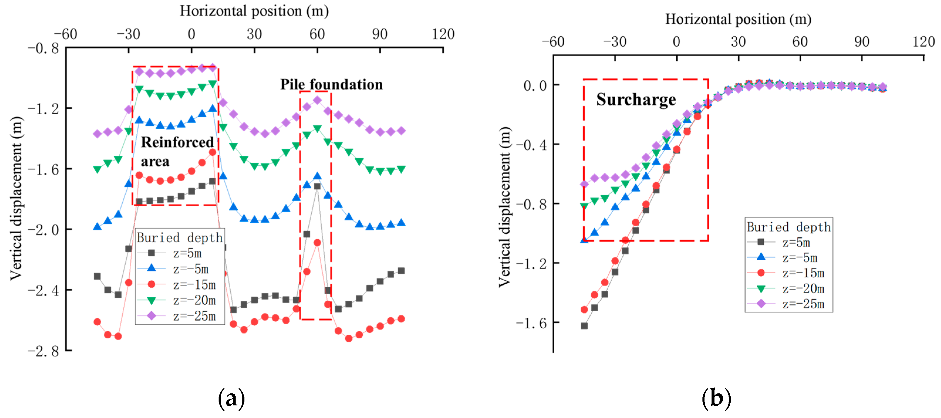
4.1.1. Analysis of Foundation Settlement

The maximum settlement of the site after preloading and before surcharge is 2.83 m, which occurs in the unreinforced area as well as on the outside of the shallow foundation reinforcement area of the gallery. Below 0 m, with the increasing depth, the vertical settlement of each stratum decreases continuously, and the settlement of the reinforced area below the surcharge and the area where the gallery pile foundations are located is obviously smaller than that of its two sides, which indicates that the reinforcement effect of piles is remarkable.
The maximum settlement of the site after surcharge is 1.85 m, which occurs at the leftmost side below the surcharge. The left side of the site sinks, and the right side rises, and the value of rises is much smaller than the value of the settlement. As the horizontal position is constantly to the right, the vertical displacement of each stratum gradually decays until the settlement is almost zero, and the influence of surcharge on the settlement and deformation of the pile foundations at the far end is very limited. With the depth constantly increasing, the vertical settlement gradually decreases. The above results are shown in Figure 5.

4.1.2. The Deformation of Pile Foundations of Adjacent Gallery

After construction, when the foundation consolidation reaches a certain degree, the displacement is cleared, and the surcharge is applied step by step, the horizontal offset of the gallery pile foundation gradually increases, with a maximum of 9.85 cm (right). It should be noted that the turning point for the horizontal offset of pile foundations, where the location shifts from decreasing to increasing, lies at −4 m. This point coincides with the boundary layer between backfill sand and silt. Additionally, the settlement of the pile foundations during the usage phase is not significant. The above results are shown in Figure 6.

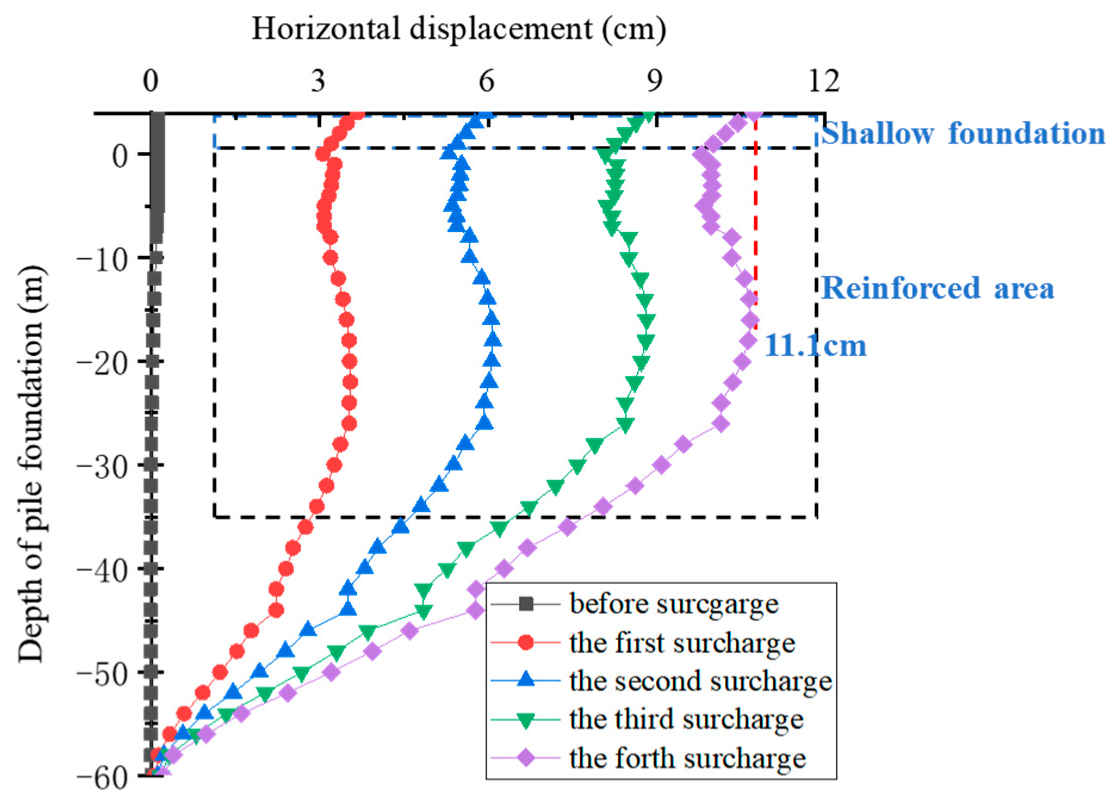
4.2. Analysis of the Impact of Mine Heaping on the Gallery Shallow Foundations

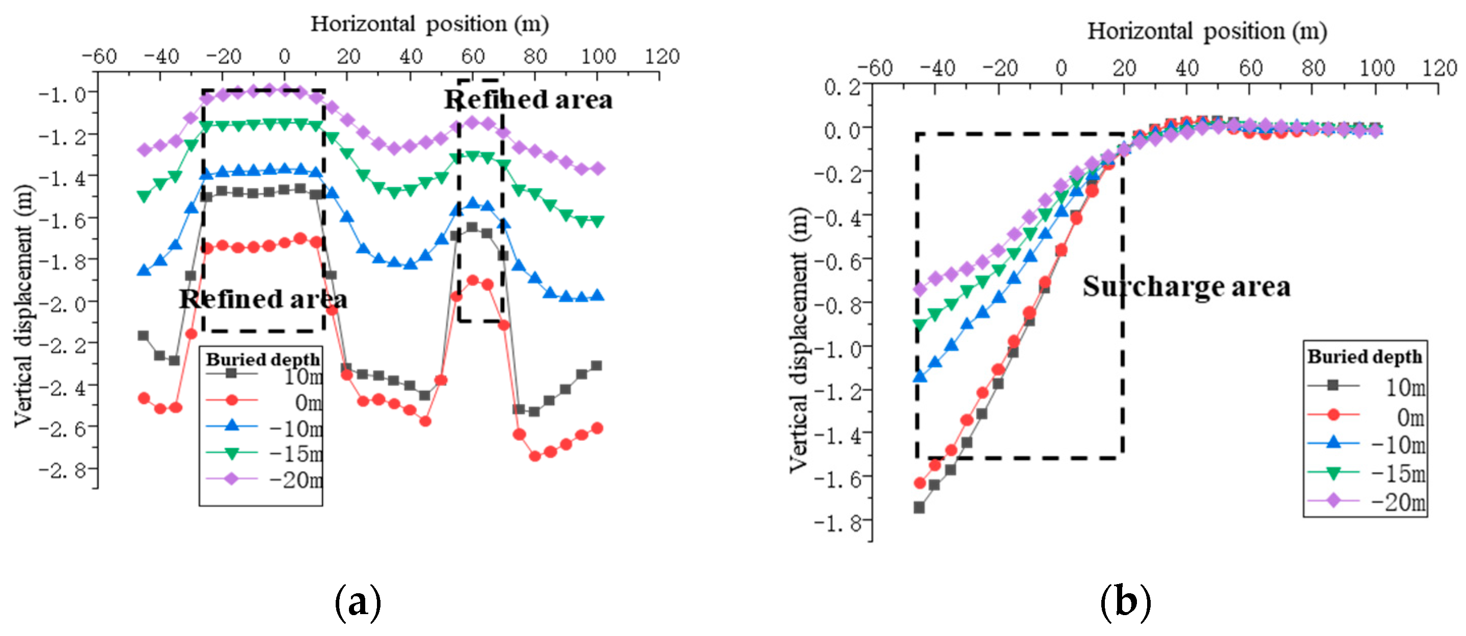
4.2.1. Analysis of Foundation Settlement

After preloading and before surcharge, the maximum settlement of the site is 2.86 m, which occurs in the unreinforced area as well as the outer side of the reinforced area of the shallow gallery foundations. Below 0 m, with increasing depth, the vertical settlement of each stratum decreases continuously. And the settlements of two reinforced areas are smaller than their settlements on both sides, which indicates that the effect of stone columns reinforcement is remarkable.
After surcharge, the maximum settlement of the site is 1.94 m, which occurs on the leftmost side below the surcharge. The left side of the site sinks, the right side rises, and the number of rises is much smaller than the settlement value. With the horizontal position continuously to the right, the vertical displacement of each stratum gradually decays until the settlement is almost zero. And the influence of surcharge on the settlement and deformation of the pile foundations at the far end is very limited. With the depth continuously increasing, the vertical settlement gradually decreases.
The displacement is cleared after preloading, and the post-work settlement of each stratum of the composite foundation under the action of large-stress load is shown in Figure 7. The figures show that there is a large vertical settlement in the foundation at the horizontal position of −66 m~20 m, i.e., the area directly under the surcharge, among which the maximum vertical settlement is 1.94 m, located in the unreinforced area under the surcharge.

4.2.2. Deformation of Adjacent Gallery Shallow Foundations

After the construction displacement is cleared to zero, the mine heaping load is applied step by step, and the horizontal offset of the gallery shallow foundations is gradually loaded. Then, the maximum horizontal displacement is 10.24 cm, located in the upper left part of the foundation, and the displacement along the center line level is 10.0 cm. As the surcharge increases, the horizontal displacement of the shallow foundation continues to rise, as illustrated in Figure 8. This pattern mirrors the previous trends observed in the process of horizontal displacement. The amplitude of horizontal displacement changes modestly within the reinforced area, initially increasing and then decreasing. Upon exiting the reinforced area, the horizontal displacement quickly decays to zero. Furthermore, the influence of the surcharge on the horizontal displacement of the composite foundation diminishes with increasing depth.

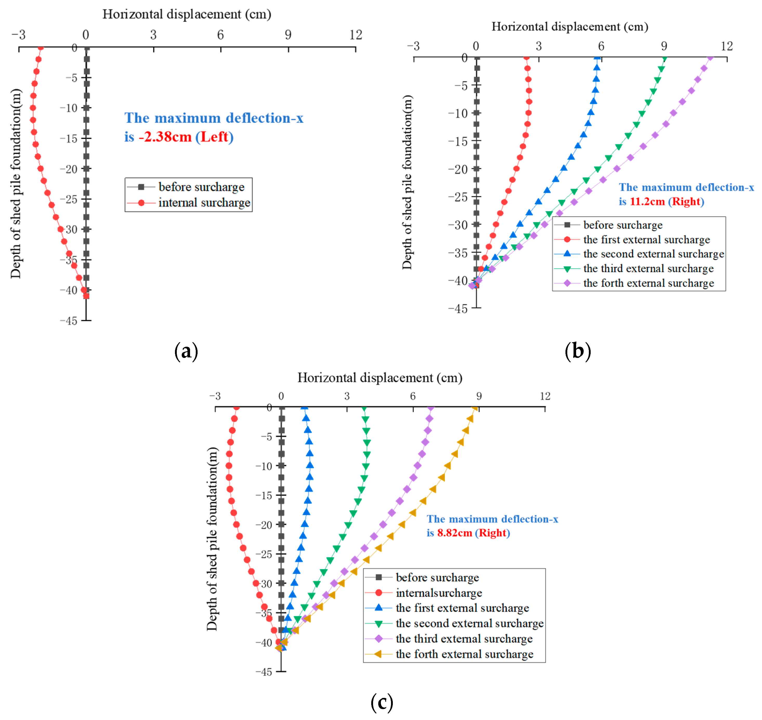
4.3. Analysis of Influence of Surcharge on Shed Pile Foundation

4.3.1. Analysis of Foundation Settlement

In this section, the post-work settlement of the foundation is investigated, and the displacement after preloading is cleared to zero. Firstly, within the internal heaping mine, the maximum settlement of the site is only 0.2 m, as shown in Figure 9a, which is located in the area directly under the surcharge and the shallow surface area. With increasing depth, the settlement of the soil under the internal surcharge is also gradually reduced. In addition, the influence range of the internal heaping mine is very small, and it has almost no effect on the left area of the stone columns on the right side.
Figure 9b reflects the changes in foundation settlement after unloading the internal surcharge and applying surcharge externally. It can be seen that the settlement is the largest in the unreinforced area of the shallow ground surface below the surcharge, which reaches 2.66 m. In general, the vertical displacement of the foundation gradually decreases from left to right, and the settlement is very small at the foot of the slope. For the strata with different burial depths, the vertical settlement is negligible far away from the foot of the slope. Therefore, the location of the steel piles for this condition is also within the safety range.

4.3.2. Deformation of Adjacent Shed Pile Foundation

The height of the internal surcharge is 6 m and the total length is 48 m, which is located at the right upper part of the steel pile, and it produces outward compression on the soil on both sides. The displacement and deformation values of each point of the steel pile are extracted, as shown in Figure 10a. The steel pile has a deformation to the left, with a horizontal offset of 2.38 cm, which is located at a burial depth of −10 m, i.e., in the silt layer. The external surcharge has a total height of 12 m and is loaded step by step four times, located at the upper left of the composite foundation, with a total length of 66 m, as shown in Figure 10b. The steel pile has a deformation to the right, and the offset keeps increasing with increasing the surcharge levels, with the maximum value reaching 11.2 cm, located at the top of the steel pile. And with the increase in the depth, the horizontal offset of the steel pile gradually decreases. We consider the surcharge process to occur as follows: after the internal surcharge is finished, it is usually unloaded and then carried to external sites. As shown in Figure 10c, the maximum horizontal offset is 2.38 cm after the internal surcharge. After unloading the internal surcharge and loading the external level by level, the offset direction of the steel pile transforms and begins to deform to the right. After four-stage loading, the maximum horizontal offset is 8.82 cm, located at the pile top, and the offset is reduced by 21.2% compared with that of Case 2. And with the increase in the depth, the horizontal offset of the steel pile is gradually reduced to zero.

4.4. Analysis of the Effect of Surcharge on the Internal Forces in the Adjacent Building Foundation

Among the three types of pile foundations, steel piles were only used for the material shed. Therefore, in this section, Case 3 will be used as the study object to discuss the effect of graded surcharge on the internal forces of the adjacent pile foundation, including axial force, shear force, and bending moment. As shown in Figure 11, the maximum horizontal shear force of −392.6 kN (left) is located at a pile foundation elevation of −34 m when the internal surcharge is applied after preloading. When the external surcharge is applied after unloading the internal one, the force direction of the steel pile changes. And the shear force on the steel pile increases gradually with the increase in the loading stage, and the maximum value of 699.4 kN (right) is located at the pile foundation elevation of −20 m, i.e., the silty chalky clay layer. For the internal force distribution of the pile foundation itself, it shows a trend of increasing first and then decreasing. The maximum axial force is 252.2 kN, located approximately at the elevation of −5 m.
The bending moment distribution of the left and right steel piles is the same, which shows that the internal surcharge pile is deformed to the left with a maximum bending moment of −841.8 kN·m. During external surcharge, the steel pile is bent to the right. And after the completion of the four-stage loading, the bending moment reaches a maximum of 1170.1 kN·m, located at a pile foundation elevation of −10 m, which is inside the silt layer.

5. Discussion

In this paper, 3D numerical simulation analyses are carried out to investigate the effects of large-scale mine heaping load on the deformation and internal force of adjacent structures in soft soil. The deployment of stone columns, prefabricated vertical drain, preloading, and other treatments is considered, aiming to improve the foundation strength and reduce the settlement. The displacement and deformation of composite foundations under large-stress mine heaping loads are evaluated. Meanwhile, a sensitivity study is carried out; and the effects of step-by-step loading and surcharge sequence on the overall deformation of the foundations are discussed. In summary, the following conclusions can be obtained from the analyses:
(1)
The horizontal displacements of the pile foundation and shallow foundation of the corridor in the using stage increase with the step-by-step loading of surcharge. The maximum horizontal offset of the former is 9.85 cm and the latter 10.24 cm, among which the turning point of the horizontal offset of the pile foundation from decreasing to increasing occurs at −4 m, located in the demarcation layer of backfill sand and silt.
(2)
The maximum settlements during both construction and operation occur in the unreinforced zone. And the settlement in the stone columns reinforced zone is less than that on both sides of it. The stone columns are effective in blocking the slip surface, which to some extent reduces the effect of large-stress surcharge on the pile offsets.
(3)
Taking Case 3 as an example, after internal surcharge, the steel pile is deflected to the left by 2.38 cm. After unloading the internal surcharge and applying an external one, the pile is deflected to the right by 8.82 cm. And the amount of deflection is reduced by 21.2% compared to 11.2 cm for only external surcharge, which shows the importance of the surcharge process.
(4)
The horizontal shear force on the pile foundation increases with the increase of surcharge, which is consistent with the response law of its horizontal deflection. A corresponding bending moment is generated, and the change in internal force is coordinated with the displacement and deformation.
There are also some research directions to follow in the future. The purpose of this article is to investigate the effects of large-scale surcharge on the deformation and internal force of adjacent structures in soft soil and raise some measures to reduce the displacement and force. For further research, a reliability analysis can be conducted and the failure probability in different conditions can be evaluated based on random field theory and machine learning [18]. Also, we have noticed that in this project, there are several layers of soft soil, which make the FDM discrete equations more complex. To figure out the effect of heterogeneous media on numerical calculations, further research can focus on the formation and soil parameter variability.

Author Contributions

Conceptualization, W.L.; Methodology, J.Z. and H.C.; Validation, J.N.; Formal analysis, H.C.; Investigation, J.Z. and D.Z. All authors have read and agreed to the published version of the manuscript.

Funding

This research received no external funding.

Data Availability Statement

Data will be made available on request.

Conflicts of Interest

Wu Li was employed by the company CCCC Third Harbor Consultants Co., Ltd. The remaining authors declare that the research was conducted in the absence of any commercial or financial relationships that could be construed as a potential conflict of interest.

References

  1. Zheng, G.; Zhou, H. State-of-the-Art Review of Ultimate Bearing Capacity and Stability of Composite Foundations. J. Tianjin Univ. Sci. Technol. 2020, 5, 661–673. [Google Scholar]
  2. Gong, X. Generalized composite foundation theory and engineering applications. Chin. J. Geotech. Eng. 2007, 29, 1–13. [Google Scholar]
  3. Zhang, J.; Phoon, K.K.; Zhang, D.; Huang, H.; Tang, C. Novel approach to estimate vertical scale of fluctuation based on CPT data using convolutional neural networks. Eng. Geol. 2021, 294, 106342. [Google Scholar] [CrossRef]
  4. Zhang, J.; Huang, H.; Zhang, D.; Phoon, K.K.; Tang, C. Simplified methods for deformation analysis of tunnel structures considering spatial variability of soil properties. Chin. J. Geotech. Eng. 2022, 44, 134–143. [Google Scholar]
  5. Zhang, J.; Huang, H.; Zhang, D.; Phoon, K.K. Experimental study of the coupling effect on segmental shield tunnel lining under surcharge loading and excavation unloading. Tunn. Undergr. Space Technol. 2023, 140, 105199. [Google Scholar] [CrossRef]
  6. Shao, W. Analysis of deformation and stability of embankment on soft ground reinforced by gravel piles. Highway 2021, 66, 58–66. [Google Scholar]
  7. Zhang, N.; Xiao, T. Study on Numerical Simulation of Soft Soil Foundation Reinforced by Gravel Pile. Water Resour. Power 2020, 38, 111–115. [Google Scholar]
  8. Chen, J.; Su, Y.; Zhang, J.; Liu, S. Overall shear strength of stone column-soil composite ground. Port Waterw. Eng. 2016, 5, 146–148+161. [Google Scholar]
  9. Han, R.; Xu, M.; Qiao, X.; Wang, H.; Guo, W. Vibro-replacement stone column tests and parameter controls of underwater super soft soil foundation. Chin. J. Geotech. Eng. 2013, 35, 612–616. [Google Scholar]
  10. Yang, T.; Ai, C.; Zhang, X.; Yang, E.; Peng, H. Comparative Analysis of the Effects of Prefabricated Vertical Drain and Gravel Pile on Soft Soil Foundation Treatment. Highway 2013, 5, 89–93. [Google Scholar]
  11. Chang, T.; Wang, C.; Fang, L. An unfunctional case of vertical drains-reinforced soft foundation. Chin. J. Geotech. Eng. 2020, 42, 2034–2039. [Google Scholar]
  12. Zhang, W.; Chen, S.; Wei, W. Settlement Law of Composite Soft Soil Foundation Under Pile-loading. J. Basic Sci. Eng. 2021, 29, 729–740. [Google Scholar]
  13. Chen, J.; Zhao, Q.; Peng, S. Settlement evaluation of soft soil foundation reinforced with stone column due to embankment load. J. Eng. Geol. 2015, 23, 505–510. [Google Scholar]
  14. Jiang, J.; Zhang, T.; Ou, X.; Chai, W.; Long, Y. Time-Effect Analysis on Influence of Excavation on Adjacent Pile Deformation in Soft Soil. J. Hunan Univ. Nat. Sci. 2022, 49, 206–215. [Google Scholar]
  15. Zhan, J.; Shui, W.; Chen, G.; Liang, Y.; Hong, C. Foundation treatment case study of fill area nearby buildings in Shanghai soft soil. Chin. J. Geotech. Eng. 2010, 32, 310–313. [Google Scholar]
  16. Kamiński, K.; Świta, K. Generalized Stochastic Finite Element Method in elastic stability problems. Comput. Struct. 2011, 89, 1241–1252. [Google Scholar] [CrossRef]
  17. Kamiński, K.; Świta, K. Structural stability and reliability of the underground steel tanks with the Stochastic Finite Element Method. Arch. Civ. Mech. Eng. 2015, 15, 593–602. [Google Scholar] [CrossRef]
  18. Wang, Z.Z.; Zhang, J.Z.; Huang, H.W. Interpreting random fields through the U-Net architecture for failure mechanism and deformation predictions of geosystems. Geosci. Front. 2024, 15, 101720. [Google Scholar] [CrossRef]
Figure 1. Constitutive model of hardening soil (HS).
Buildings 14 01596 g001
Figure 2. Model of composite foundation and gallery pile foundation under surcharge.
Buildings 14 01596 g002
Figure 3. Model of composite foundation and gallery shallow foundation under surcharge.
Buildings 14 01596 g003
Figure 4. Model of composite foundation and shed pile foundation under surcharge.
Buildings 14 01596 g004
Figure 5. Settlement of composite pile foundation: (a) after preloading and before surcharge; (b) after surcharge.
Buildings 14 01596 g005
Figure 6. Horizontal deviation of gallery pile foundation after surcharge.
Buildings 14 01596 g006
Figure 7. Settlement of shallow foundation: (a) after preloading and before surcharge; (b) after surcharge.
Buildings 14 01596 g007
Figure 8. Horizontal deviation of gallery shallow foundation after surcharge.
Buildings 14 01596 g008
Figure 9. Settlement of composite foundation: (a) internal surcharge; (b) external surcharge.
Buildings 14 01596 g009
Figure 10. Horizontal deviation of shed pile foundation: (a) only internal surcharge; (b) only external surcharge; (c) first internal and second external surcharge.
Buildings 14 01596 g010
Figure 11. Internal force distribution of adjacent pile foundations: (a) horizontal shear force; (b) axial force; (c) moment.
Buildings 14 01596 g011
Table 1. Soil profile and soil parameters of gallery foundation.
Soil LayerThickness
/m
Unit Weight
γ /kN·m−3
c
/kPa
ϕ
ψ
E o e d r e f
/MPa
E 50 r e f
/MPa
E u r r e f
/MPa
υ u r p r e f
/kPa
K 0 m R f
backfill stone 5.118526078.4840.31000.50.80.9
1 muddy416.1221502.12.3116.170.331000.60.90.9
1 muddy silty clay416.96.028.102.32.5317.710.301000.60.80.8
2-1 muddy clay1016.66.427.302.12.3116.170.321000.50.80.8
2-2 muddy clay1516.79.026.602.42.6418.480.311000.50.80.8
2 silty clay1717.77.031.003.63.9627.720.281000.50.80.9
1 silty clay2.919.21232.006.16.7146.970.271000.50.80.9
3 silt3.5206.036.0011.913.0991.630.261000.50.80.9
Table 2. Pile and stone block parameters.
Type of PileThickness or Length/mDiameter
/mm
Unit Weight
/kN·m−3
Cohesive
/kPa
Internal
Friction Angle/°
Elastic
Modulus/MPa
Poisson’s Ratio
backfill stone6 18040550.18
Stone columns3080023520450.25
cast-in-place pile6080023.5 30,0000.2
Table 3. Soil profile and soil parameters of pile foundation.
Soil LayerThickness
/m
Unit Weight
γ /kN·m−3
c /kPa ϕ
ψ
E o e d r e f
/MPa
E 50 r e f
/MPa
E u r r e f
/MPa
υ u r p r e f
/kPa
K 0 m R f E
/MPa
backfill stone 5.8180400 0.15 55
backfill sand 3.218026078.4840.31000.50.80.9
1 muddy10.516.11012.402.12.3116.170.351000.60.90.9
1 muddy silty clay816.910.617.202.32.5317.710.351000.60.80.8
2-1 muddy clay616.610.813.602.12.3116.170.321000.50.80.8
2-2 muddy clay816.712.314.302.42.6418.480.321000.50.80.8
2 silty clay117.712.720.403.63.9627.720.31000.50.80.9
1 silty clay 419.235.41606.16.7146.970.31000.50.80.9
stone columns3023520 0.25 45
steel pile5078.50 0.3 2 × 10⁵
Disclaimer/Publisher’s Note: The statements, opinions and data contained in all publications are solely those of the individual author(s) and contributor(s) and not of MDPI and/or the editor(s). MDPI and/or the editor(s) disclaim responsibility for any injury to people or property resulting from any ideas, methods, instructions or products referred to in the content.

