Article

Flexural Behavior of Partially Encased Composite Beams with a Large Tensile Reinforcement Ratio

1
College of Intelligent Construction, Wuxi Taihu University, Wuxi 214064, China
2
College of Civil Engineering, Nanjing Tech University, Nanjing 211816, China
3
School of AI and Advanced Computing, Xi’an Jiaotong-Liverpool University, Suzhou 215028, China
*
Author to whom correspondence should be addressed.
Buildings 2024, 14(6), 1606; https://doi.org/10.3390/buildings14061606
Submission received: 8 May 2024 / Revised: 24 May 2024 / Accepted: 27 May 2024 / Published: 1 June 2024
(This article belongs to the Section Building Structures)

Abstract

:
Partially encased composite beams (PECBs) have advantages over conventional steel–concrete composite beams in load-carrying capacity, flexural stiffness and fire resistance. In order to determine whether the shearing force is sufficient to ensure the yield of the tensile reinforcement in the case of a large tensile reinforcement ratio, as well as the influence of encasing concrete strength and the addition of studs on the steel web, three PECB specimens were tested under bending. The results show that, in the case of a 5% tensile reinforcement ratio, natural bonding and friction forces ensure the yield of tensile reinforcement whether studs are added on the steel web or not. The encasing concrete strength and the addition of studs on the steel web have no obvious effect on both the elastic and plastic bending resistance of PECBs. The addition of studs on the steel web significantly slows down the stiffness deterioration of PECBs within the elastoplastic stage, while the flexural stiffness is not obviously affected by the strength of encasing concrete. The simplified plastic theory is proved to be applicable to predict the flexural capacity of PECBs with a large tensile reinforcement ratio. It is also indicated by calculation that, by increasing the tensile reinforcement ratio from 2% to 5%, the flexural capacity of PECBs has a significant increase, by about 32%.

1. Introduction

Partially encased composite beams (PECBs) are steel–concrete composite beams with reinforced concrete encased between the steel flanges. Shear connectors such as studs are usually installed on the steel web to ensure that the steel beam and the encasing concrete behave as a whole [1,2]. Initially, the PECBs were designed in view of fire protection, as the presence of encasing concrete inhibited the temperature of the structural steel from rising too quickly under fire conditions [3,4,5,6]. Subsequent studies show that the encasing concrete contributes to the load-carrying capacity and flexural stiffness [1,7,8,9], and also effectively prevents the steel section from buckling [2,9,10,11,12].
Up to now, numerous studies on the mechanical behavior of PECBs have been carried out. Kindmann et al. [7] performed experiments on a series of PECB specimens with different cross-sections, and concluded that the encasing concrete and its axial reinforcement made important contributions to the load-carrying capacity and flexural stiffness of composite beams. Additionally, all test specimens behaved as composite elements whether or not mechanical connections were added to the steel web. Nakamura and Narita [9] performed bending and shearing tests on partially encased I-beams, demonstrating that both the bending and shearing strength of the partially encased I-beam were much higher than those of the conventional I-beam. Also, the encasing concrete effectively inhibited the buckling of the compressive flange. Hegger and Goralski [8] investigated the flexural behavior of PECBs with and without mechanical connections and found that, under a positive bending moment, mechanical connections in the web encasement had little influence on the flexural behavior of PECBs. Friction forces between the steel flanges and the encasing concrete mostly carried the shearing action. Hu et al. [1] conducted bending tests on one ordinary composite beam and three PECBs with different connection types on the steel web. The findings showed that the connection type on the steel web had no apparent influence on the load-carrying capacity and flexural stiffness of PECBs under a positive bending moment. Compared with conventional composite beams, PECBs have higher flexural capacity and deformation resistance. Jiang et al. [2,11] successively investigated the flexural behavior of PECBs under negative bending, and the redistribution behavior of internal forces in partially encased continuous composite beams, respectively. To avoid the use of shear connectors in the steel web, Wang et al. [13] and Zhao et al. [14] proposed a new type of PECB in which the commonly used H-shape beam is replaced by a cellular beam or castellated beam. In experiments, the cellular or castellated PECBs showed satisfying flexural behavior, and full composite action was achieved without installing shear connectors on the steel web. Chu et al. [15] experimentally studied the flexural behavior of PECBs with corrugated steel webs, and the results showed that PECBs in the proposed form had a high load-carrying capacity and superior ductility.
Many existing studies have shown that the presence or absence of mechanical connections on the steel web has no significant effect on the flexural behavior of PECBs under a positive bending moment, which means that the longitudinal shearing force can be transmitted by natural bonding and friction forces [1,7,8]. For the conservative design, however, EN 1994-1-1 [16] specifies a maximum stud spacing of 400 mm on the steel web. An important factor that has been rarely considered is the tensile reinforcement ratio in the web encasement, which governs whether the shearing force is sufficient to ensure that longitudinal reinforcement achieves the design strength. The tensile reinforcement ratio that has been investigated by Kindmann et al. [7], Hegger and Goralski [8] and Hu et al. [1] is 1.9%, 3.2% and 2.0%, respectively, which is far less than the upper limit of the fire design in EN 1994-1-2 [17].
In order to determine whether the shearing force is sufficient to ensure the yield of the tensile reinforcement in the case of a large tensile reinforcement ratio, as well as the influence of encasing concrete strength and the addition of studs on the steel web, the flexural behavior of PECBs with a large tensile reinforcement ratio was experimentally studied in this paper. In addition, the theoretical flexural capacity of PECBs under positive bending is calculated and verified by the experimental results.

2. Materials and Methods

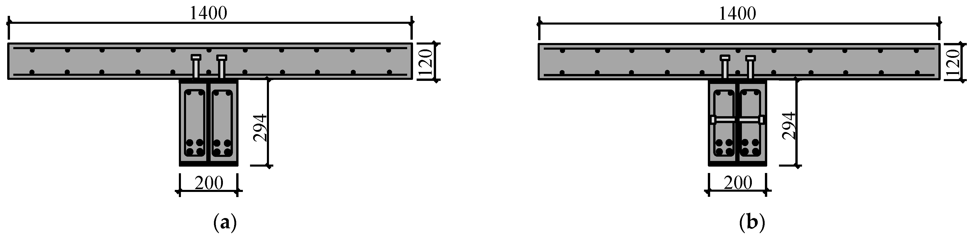
2.1. Specimen Details
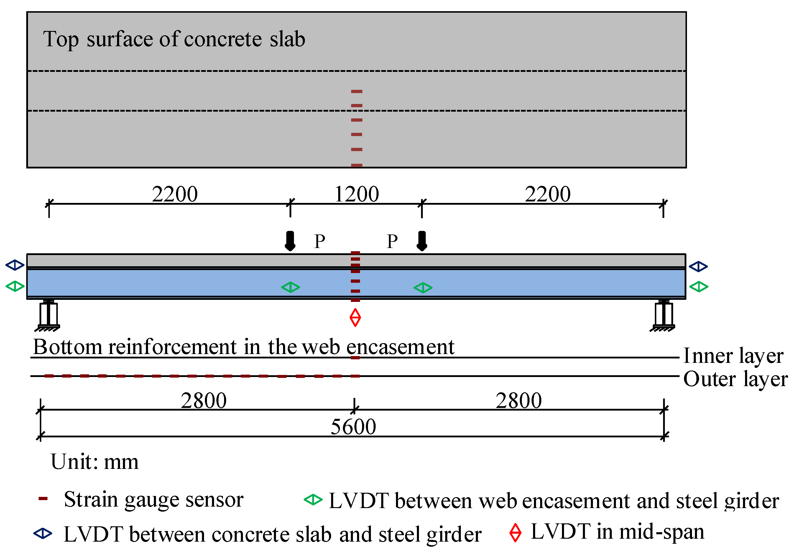
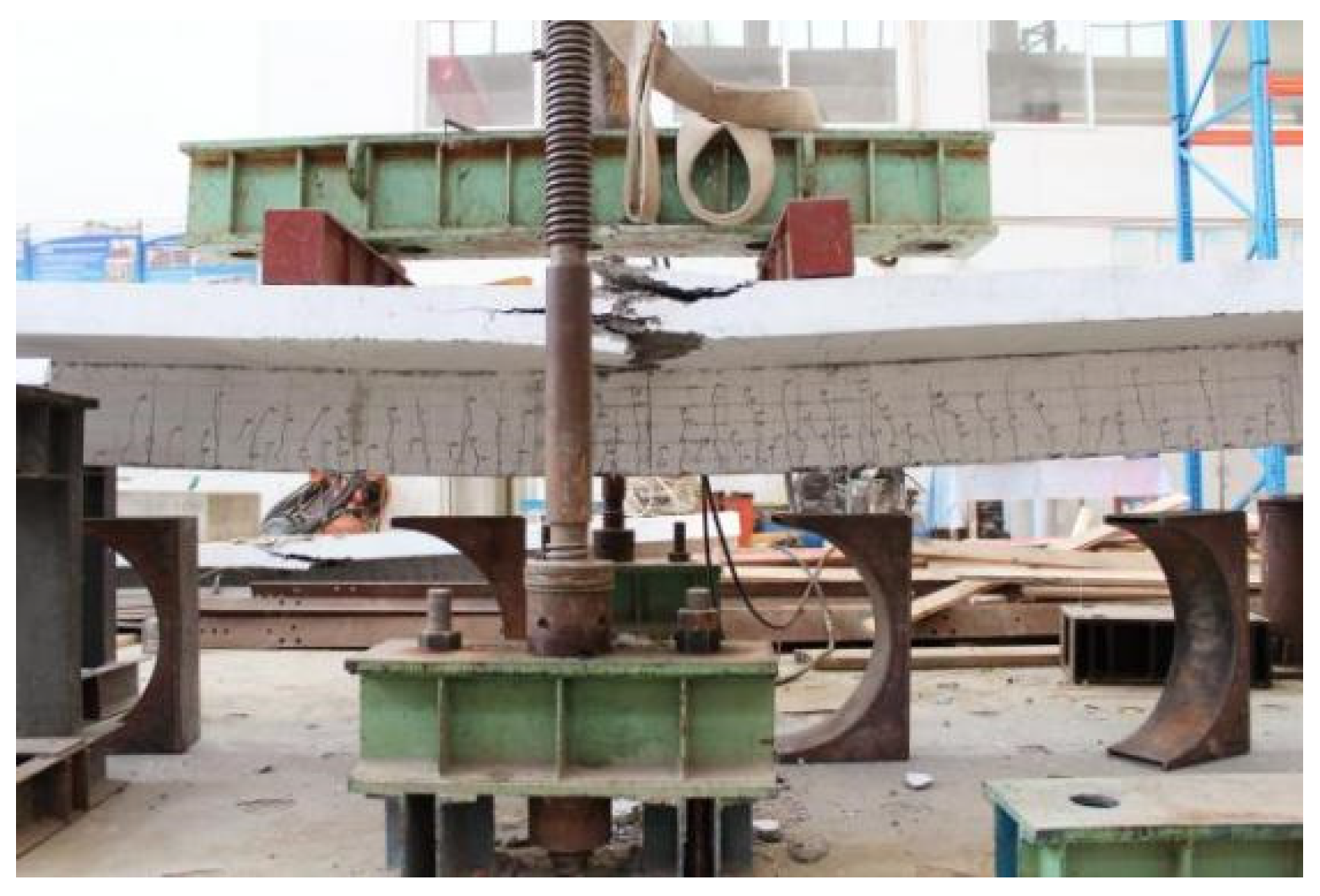
Three full-scale PECB specimens with a span of 5600 mm were designed for testing. The cross-sections of the PECB specimens are illustrated in Figure 1. Two rows of M19 × 80 studs are welded on the top steel flange, with a transverse and longitudinal spacing of 80 mm and 100 mm, respectively. The stud spacing is determined with EN 1994-1-1 [16] to provide full shear connection. For specimen PECB3, additional studs (M19 × 80) with a longitudinal spacing of 300 mm are welded on the centerline of the steel web, which meets the requirement of EN 1994-1-1 for a maximum stud spacing of 400 mm. The tensile reinforcement ratio for all PECB specimens is designed as 5%, which is determined as the upper limit of the fire design in EN 1994-1-2 [17]. The concrete covers of the concrete slab and the concrete encasement for all PECB specimens meet the requirements for exposure class XC1 according to EN 1992-1-1 [18]. Configuration details of PECB specimens are summarized in Table 1.
During the production of PECB specimens, two sides of the encasing concrete and the concrete slab were poured in batches. Three 150 mm × 150 mm × 150 mm concrete cubes were reserved for each batch and tested in accordance with Chinese standard GB/T 50081-2019 [19]. Table 2 shows the average compressive strength and coefficient of variation (in brackets) of concrete cubes. According to Chinese standard GB/T 228-2010 [20], the tensile properties of structural steel, bars and studs were tested with five samples, respectively, and the average values and coefficient of variation (in brackets) are listed in Table 3.

2.2. Loading Set-Up

All PECB specimens were subjected to four-point bending, as illustrated in Figure 2. The load was applied in two phases: 20 kN/step until 70% of the estimated failure load, and then 5 kN/step until failure. In the experimental process, the applied load, mid-span deflection, maximum crack width, strain along the height of the mid-span section, strain along the width of the concrete slab, strain of tensile reinforcement in the concrete encasement and relative slip between the components of the composite beams were monitored.

3. Results and Discussion

3.1. Experimental Observation

In all PECB specimens, the initial vertical crack appeared in the web encasement near the mid-span section at about 24% of the failure load. As the load increased, more cracks gradually developed and existing cracks extended upward at a moderate speed. At about 40% of the failure load, interfacial cracks appeared between the steel beam and the encasing concrete accompanied by a continuous sound, indicating that the natural bonding began to fail. When approaching about 90% of the failure load, cracks near the mid-span ran through the encasing concrete, and then transverse cracks turned up on the bottom of the concrete slab. Eventually, all PECB specimens failed due to the crushing of the concrete slab at the mid-span (Figure 3). For specimens PECB1 and PECB2, an obvious slip between the web encasement and the steel beam at the beam end was observed near the failure load (Figure 4a,b), while for specimen PECB3 no visible slip was observed during the whole loading process (Figure 4c).
The primary experimental results are given in Table 4, in which My is the bending moment when the bottom steel flange yields; Mu is the ultimate bending moment; and δy and δu represent the mid-span deflections corresponding to My and Mu, respectively. As shown in Table 4, the maximum relative deviations for yielding bending moments and ultimate bending moments of the three PECB specimens are 4.2% and 1.1%, respectively. It can be concluded that the encasing concrete strength and the addition of studs on the steel web have no obvious effect on both the elastic and plastic bending resistance of PECBs. However, the value of δy for specimen PECB3 is much smaller than those for specimen PECB1 and PECB2, which indicated that the deformation resistance of PECBs can be enhanced by adding studs on the steel web. In addition, all three PECB specimens are proved to have good ductility, with the displacement ductility coefficients δu/δy much larger than 3.0. In addition, by comparison with the test results from Hu et al. [1], the average displacement ductility coefficient of PECBs with a 5% tensile reinforcement ratio is about twice that of PECBs with a 2% tensile reinforcement ratio.

3.2. Load–Deflection Behavior

As shown in Figure 5, the load–deflection relationship of PECBs is generally divided into three stages: elastic, elastoplastic and plastic stages. The load–deflection curves develop almost linearly in the elastic stage. When about 35% of the failure load is reached, the load–deflection curves enter the elastoplastic stage, in which the deflection grows faster and the flexural stiffness degenerates gradually due to the acceleration of crack development and the yielding of the structural steel. After loading to 80% of the failure load, the load–deflection curves enter the plastic stage, in which the deflection grows dramatically with only a marginal increase in the load. By comparison, it can be concluded that the addition of studs on the steel web significantly slows down the stiffness deterioration of PECBs in the elastoplastic stage, while the flexural stiffness of PECBs is not obviously affected by the strength of the encasing concrete. It is worth noting that in the studies performed by Hu et al. [1] and Kindmann et al. [7], there is no significant difference in the stiffness deterioration of PECBs with and without studs on the steel web. It is indicated that, in the case of a large tensile reinforcement ratio, weak shear connections between the steel beam and the encasing concrete will lead to stiffness deterioration in PECBs.

3.3. Slip between Steel Beam and Concrete Encasement

The variations in slip between the steel beam and the concrete encasement with the test load at the loading point and the beam end are illustrated in Figure 6a and Figure 6b, respectively. Different from the typical slip distribution law between the steel beam and concrete slab in a regular steel–concrete composite beam [21,22], the relative slip between a steel beam and its web encasement in PECBs tends to be larger at the loading point and smaller at the beam end, which is due to the fact that under the positive bending the encasing concrete cracks significantly near the loading point, resulting in discontinuous slip distribution. In the elastic and elastoplastic stages, the slip of all PECB specimens grows quite slowly and is basically less than 0.4 mm. In the plastic stage, the slip of the PECB specimen with stud connections on the steel web is still less than 0.4 mm, while the slip of PECB specimens with only natural bonding increases rapidly and eventually exceeds 1.6 mm.

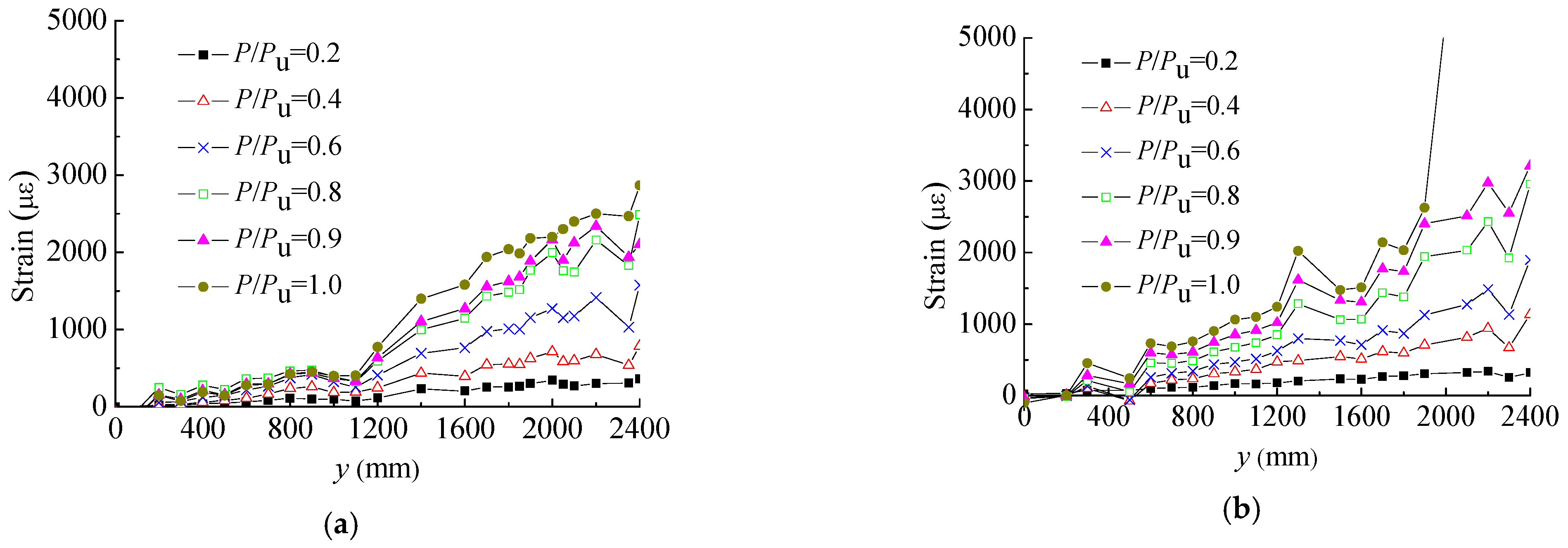
3.4. Strain Distribution along the Width of the Concrete Slab

The strain distribution along the width of the concrete slab in the mid-span for PECB specimens is illustrated in Figure 7, where the abscissa x is the distance from the centerline of the concrete slab. It can be seen that before 90% of the failure load the concrete strain is almost evenly distributed along the width of the slab; when approaching the failure load, the shear lag effect begins to be prominent while the concrete strain basically has reached or approached the ultimate compressive strain, which demonstrates that the slab width designed in this test is reasonable.

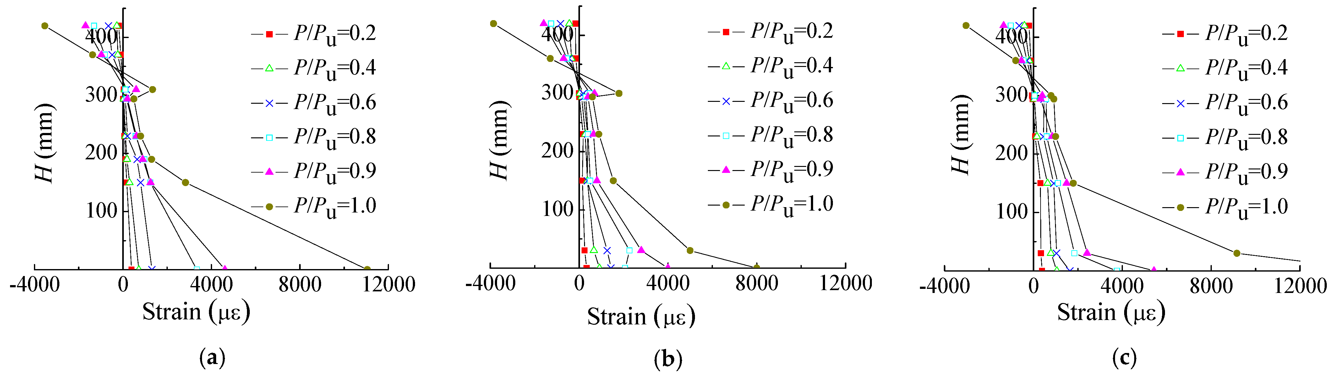
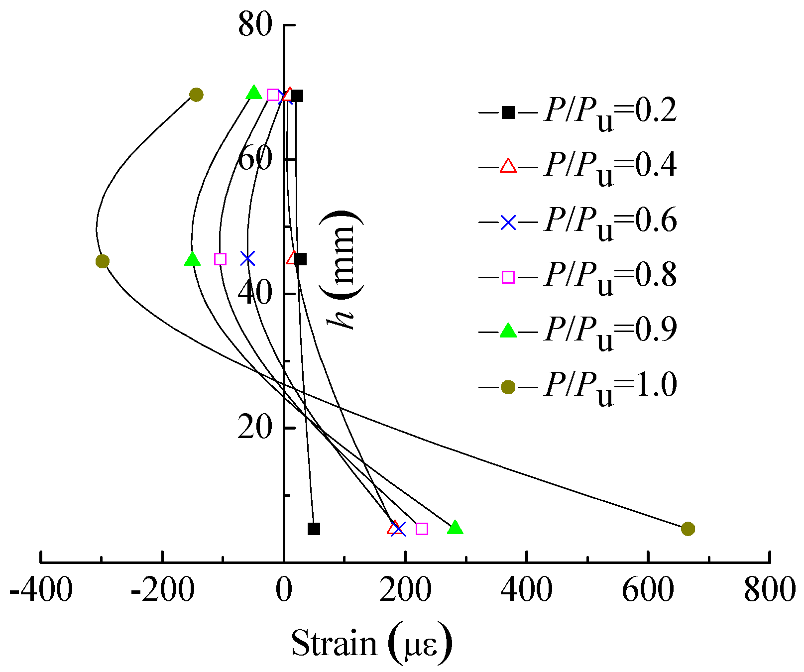
3.5. Strain Distribution along the Height of the Mid-Span Section

The strain distribution along the height of the mid-span section of PECB specimens is shown in Figure 8 and Figure 9, where the ordinate H is the distance from the bottom surface of the steel beam. It is indicated that almost no strain difference at the interface of the steel beam and the concrete slab exists before 90% of the failure load; at the failure load, the strain difference at the interface is also small, which means that the steel beam is fully shear-connected with the concrete slab. The neutral axis of the composite section is always located in the concrete slab, and the entire structural steel section is in a tensile state. Furthermore, the vast majority of the structural steel section has entered the yield stage under the failure load. It is also indicated in Figure 9 that the addition of studs on the steel web significantly affects the strain distribution along the height of the concrete encasement. The strain difference between the steel beam and the encasing concrete of the PECB specimen with studs on the steel web is less than that of the PECB specimen with only natural bonding. In specimens PECB1 and PECB2, the top area of the encasing concrete is even under compression due to the deformation inconsistency with the steel beam.

3.6. Strain Distribution of the Stud on the Steel Web

The strain distribution of the stud on the steel web in the shearing span of specimen PECB3 is shown in Figure 10, where the ordinate h is the distance from the stud root. It is shown that the strain of the stud increases with the load, whereas the maximum strain is far less than the yield strain of the stud up to the failure load. This indicates that natural bonding and friction forces play a considerable role in the transmission of longitudinal shear, and the maximum spacing of studs on the steel web specified by EN 1994-1-1 [16] seems to be conservative.

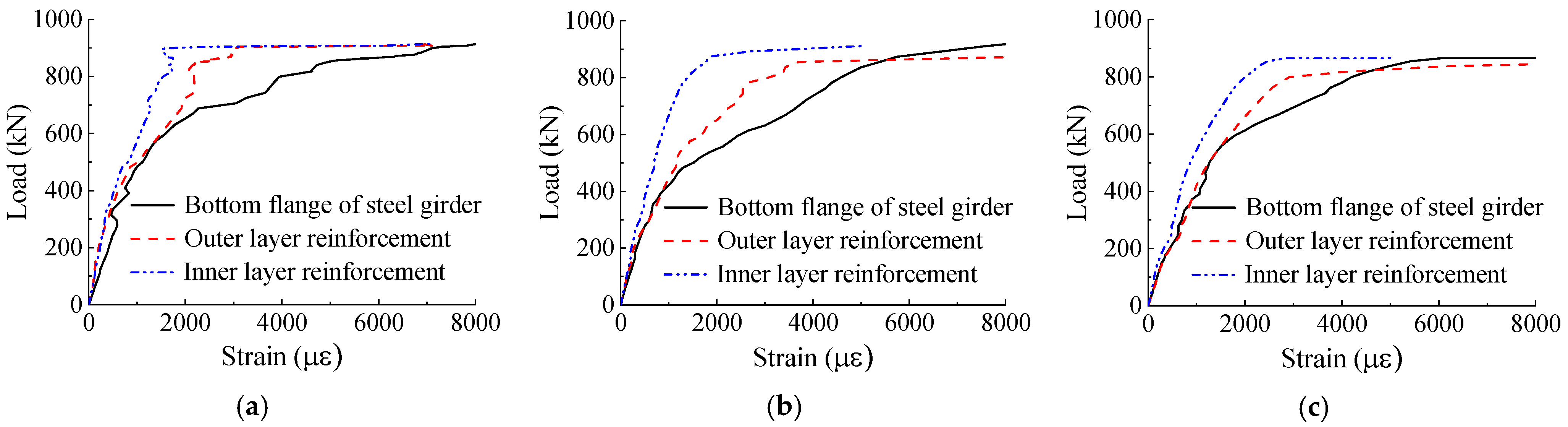
3.7. Strain of the Bottom Steel Flange and the Tensile Reinforcement

The load–strain curves of the bottom steel flange and the tensile reinforcement are shown in Figure 11. As can be seen in the mid-span section of all three PECB specimens, the bottom steel flange, the outer and the inner layers of tensile reinforcement in the web encasement yield sequentially. The steel bars exhibit ideal elastic–plastic behavior, while the structural steel has a significant hardening stage after yielding.
The strain distribution along the tensile reinforcement within the shearing span of specimens PECB1 and PECB3 was compared in Figure 12, where the abscissa y is the distance from the support. It is indicated that the strain distribution of the tensile reinforcement for specimen PECB3 is more linear, while for specimen PECB1 the strain of the tensile reinforcement near the support area basically no longer increases after 60% of the failure load. This is mainly due to the complete failure of the natural bonding near the support area, resulting in strain disharmony between the tensile reinforcement and the steel beam.

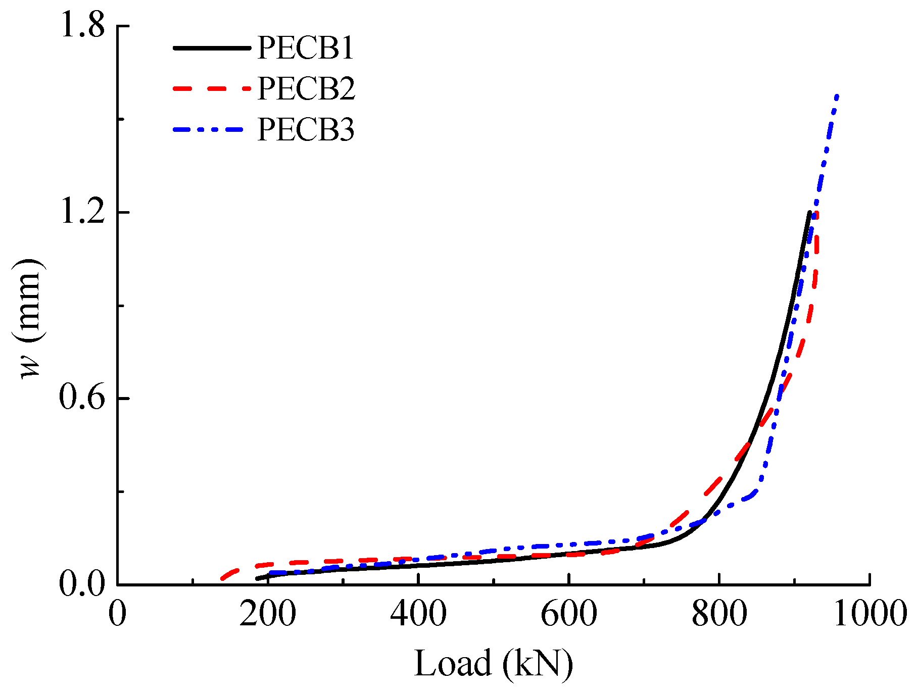
3.8. Maximum Crack Width on the Concrete Encasement

Figure 13 shows the development of the maximum crack width on the concrete encasement for PECB specimens, where w is the maximum crack width. Due to the constraints of the steel web and flanges, the maximum crack width develops quite slowly in both the elastic and elastoplastic stages of all PECB specimens. In the plastic stage of PECB specimens, when the tensile reinforcement in the web encasement is close to the yield strength, the crack width develops rapidly and the maximum crack width exceeds 1.2 mm under the failure load. In the service stage of PECB specimens, however, the maximum crack width is no bigger than 0.3 mm, which meets the requirements of the serviceability limit state for all exposure classes in EN 1992-1-1 [18]. The addition of studs on the steel web and the encasing concrete strength shows almost no effect on the development of the maximum crack width.

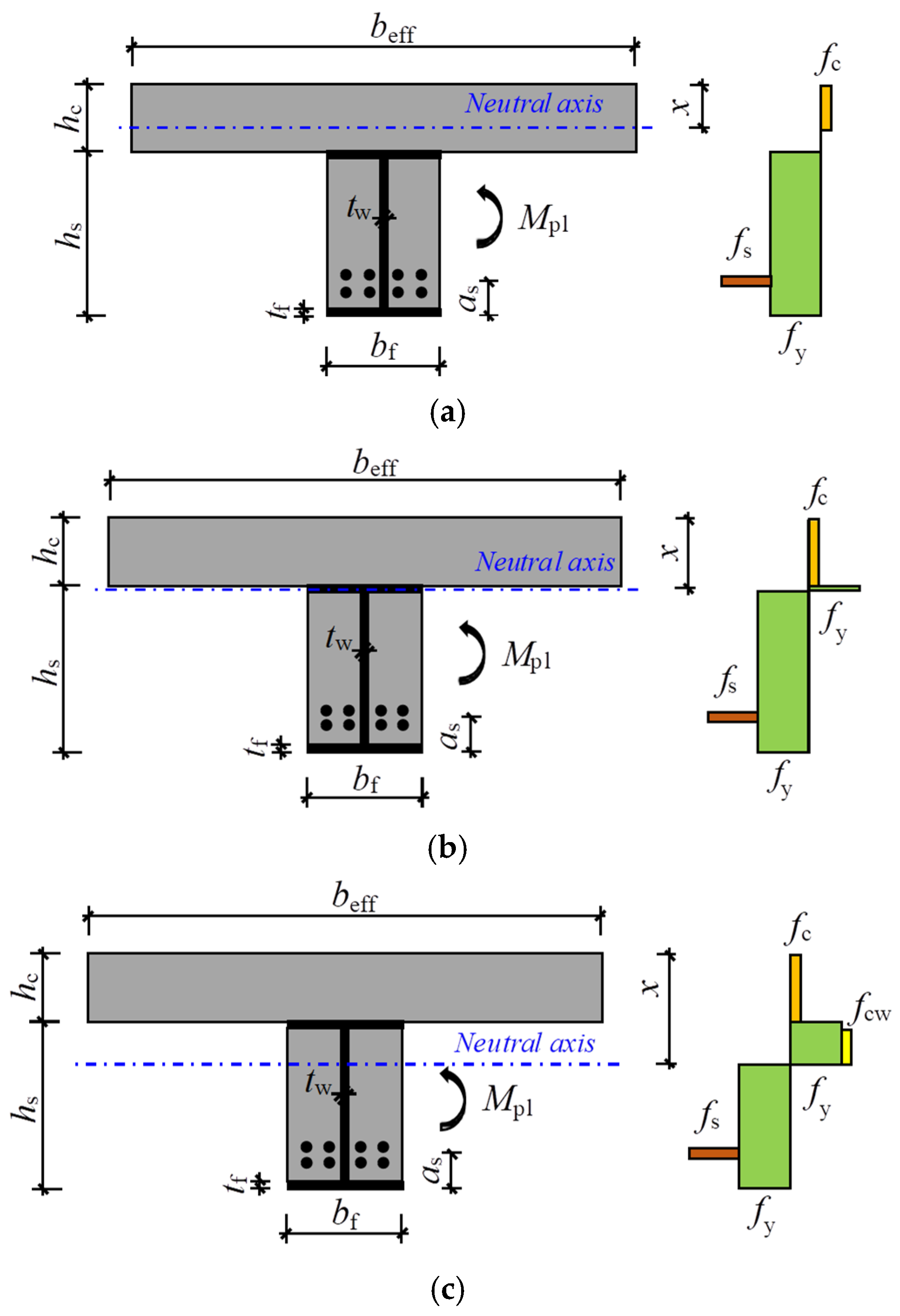
4. Calculation of Ultimate Flexural Capacity

In accordance with EN 1994-1-1 [16], the cross-section of specimen PECB3 completely satisfies the requirements of Class 1 section, and the suggested plastic theory can be applied to determine its flexural capacity. For specimens PECB1 and PECB2, where the web encasement is not mechanically connected to the structural steel section, EN 1994-1-1 does not give a specific section classification and calculation recommendations. However, the test results in this paper show that in the mid-span section the tensile reinforcement and most of the area of the structural steel section can eventually reach the yield strength, whether it is a PECB specimen with or without studs on the steel web. As a result, the simplified plastic theory suggested by EN 1994-1-1 seems feasible to predict the flexural capacity of PECBs.
For the three possible situations when the plastic neutral axis of the composite section locates within the concrete slab, the upper steel flange and the steel web, the stress distributions of the composite section are illustrated in Figure 14a–c, respectively, where Mpl is the flexural capacity predicted by the plastic theory; x is the distance between the plastic neutral axis and the top surface of the concrete slab; beff is the effective width of the concrete slab; bf is the width of the steel flange; hs and hc are the height of the structural steel section and the concrete slab, respectively; tf and tw are the thickness of the steel flange and the steel web, respectively; as is the distance between the center of the tensile reinforcement and the bottom of the structural steel; fc and fcw are the compressive concrete strength of the slab and the web encasement, respectively; and fy and fs are the yield strength of the structural steel and the tensile reinforcement, respectively.
When the plastic neutral axis of the composite section locates within the concrete slab, the flexural capacity of PECBs can be calculated as
x = F a + F s / f c b eff
M pl = F a h s / 2 + h c x / 2 + F s h s + h c a s x / 2 ,
where F a = f y A a and F s = f s A s , and Aa and As are the sectional area of the structural steel section and the tensile reinforcement, respectively.
When the plastic neutral axis of the composite section locates within the upper steel flange, the flexural capacity of PECBs can be calculated as
x = F a + F s F c / 2 f y b f + h c
M pl = F a h s + h c / 2 + F s h s + h c / 2 a s f y b f x x h c ,
where F c = f c b eff h c .
When the plastic neutral axis locates within the steel web, the flexural capacity of PECBs can be calculated as
x = F w + F s F c / 2 f y t w + f cw b f t w + h c + t f
M pl = F a h s + h c / 2 + F s h s + h c / 2 a s F f h c + t f / 2 F w + F s F c ( x + t f ) / 2 ,
where F w = F a F f and F f = 2 f y b f t f .
Comparison between the test and theoretical values of flexural capacity are shown in Table 5, in which Mpl, 2% and Mpl, 5% are the theoretical flexural capacity of PECBs with a 2% and 5% tensile reinforcement ratio, respectively; Mu is the ultimate bending moment from the test. As indicated in Table 5, the theoretical values are about 11% lower than the test results, which may be attributed to the conservative strength selected for structural steel without considering the strength-hardening behavior. However, in general, the simplified plastic theory is applicable and somewhat safe to predict the flexural capacity of PECBs with a large tensile reinforcement ratio. It should be noted that the materials’ strength in the calculation are obtained from the material tests; if the design values of the materials’ strength are used, the calculated flexural capacity will be more conservative. It is also indicated by calculation that by increasing the tensile reinforcement ratio from 2% to 5% the flexural capacity of PECBs has a significant increase, by about 32%.
In the practical design, increasing the tensile reinforcement ratio is an effective way to enhance the flexural capacity of PECBs without enlarging the cross-section. Although the longitudinal shear connection has little impact on the flexural capacity, the addition of bolts or other connectors is suggested to avoid stiffness degradation in PECBs and accidental shedding of the concrete encasement.

5. Conclusions

The flexural behavior of the three PECB specimens with a large tensile reinforcement ratio were experimentally investigated in the present paper. Some noteworthy conclusions are drawn as follows:
  • All PECB specimens failed in a fairly ductile manner, with the concrete slab at the mid-span crushed. The addition of studs on the steel web effectively inhibits the relative slip between the web encasement and the steel beam.
  • The encasing concrete strength and the addition of studs on the steel web have no obvious effect on both the elastic and plastic bending resistance of PECBs. The addition of studs on the steel web significantly slows down the stiffness deterioration of PECBs within the elastoplastic stage, while the flexural stiffness is not obviously affected by the strength of the encasing concrete.
  • In the mid-span section of all three PECB specimens, the bottom steel flange, the outer and the inner layers of tensile reinforcement in the web encasement yield sequentially as the load increases, and the vast majority of the structural steel section has entered the yield stage under the failure load. In the case of a 5% tensile reinforcement ratio, as is the upper limit of the fire design in EN 1994-1-2, natural bonding and friction forces ensure the yield of the tensile reinforcement whether studs are added on the steel web or not.
  • Due to the constraints of the steel web and flanges, the maximum crack width develops quite slowly in both the elastic and elastoplastic stages of PECB specimens, which meets the requirements of serviceability limit state.
  • In general, the simplified plastic theory is applicable and somewhat safe to predict the flexural capacity of PECBs with a large tensile reinforcement ratio.

Author Contributions

Conceptualization, Y.J. and X.H.; methodology, Y.J. and X.H.; validation, Y.J., H.Z. and H.S.; investigation, Y.J., H.Z. and H.S.; data curation, Y.J.; writing—original draft preparation, Y.J.; writing—review and editing, Y.J. and X.H.; visualization, Y.J. and H.S.; supervision, X.H.; funding acquisition, Y.J. All authors have read and agreed to the published version of the manuscript.

Funding

This research was funded by the Natural Science Research of Jiangsu Higher Education Institutions of China (22KJD560006), and the Qinglan Project of Jiangsu Province of China.

Data Availability Statement

The data presented in this study are available on request from the corresponding author.

Conflicts of Interest

The authors declare no conflicts of interest.

References

  1. Hu, X.; Jiang, Y.; Shi, Y.; Wei, T. Experimental study on flexural behavior of simply supported partially concrete encased composite beams. J. Build. Struct. 2015, 36, 37–44. (In Chinese) [Google Scholar]
  2. Jiang, Y.; Hu, X.; Hong, W.; Wang, B. Experimental study and theoretical analysis of partially encased continuous composite beams. J. Constr. Steel Res. 2016, 117, 152–160. [Google Scholar] [CrossRef]
  3. Piloto, P.A.G.; Gavilán, A.B.R.; Zipponi, M.; Marini, A.; Mesquita, L.M.; Plizzari, G. Experimental investigation of the fire resistance of partially encased beams. J. Constr. Steel Res. 2013, 80, 121–137. [Google Scholar] [CrossRef]
  4. Ahn, J.K.; Lee, C.H. Fire behavior and resistance of partially encased and slim-floor composite beams. J. Constr. Steel Res. 2017, 129, 276–285. [Google Scholar] [CrossRef]
  5. Piloto, P.A.G.; Ramos-Gavilán, A.B.; Gonçalves, C.; Mesquita, L.M. Experimental bending tests of partially encased beams at elevated temperatures. Fire Saf. J. 2017, 92, 23–41. [Google Scholar] [CrossRef]
  6. Wang, W.; Jiang, B.; Ding, F.; Wang, L. Numerical analysis on mechanical behavior of steel-concrete composite beams under fire. Struct. Des. Tall. Spec. 2023, 32, e2012. [Google Scholar]
  7. Kindmann, R.; Bergmann, R.; Cajot, L.G.; Schleich, J.B. Effect of reinforced concrete between the flanges of the steel girder of partially encased composite beams. J. Constr. Steel Res. 1993, 27, 107–122. [Google Scholar] [CrossRef]
  8. Hegger, J.; Goralski, C. Structural behavior of partially concrete encased composite sections with high strength concrete. In Proceedings of the Composite Construction in Steel and Concrete V, Kruger National Park, South Africa, 18–23 July 2006; pp. 346–355. [Google Scholar]
  9. Nakamura, S.; Narita, N. Bending and shear strengths of partially encased composite I-girders. J. Constr. Steel Res. 2003, 59, 1435–1453. [Google Scholar] [CrossRef]
  10. He, J.; Liu, Y.; Chen, A.; Yoda, T. Bending behavior of concrete-encased composite I-girder with corrugated steel web. Thin-Walled Struct. 2014, 74, 70–84. [Google Scholar] [CrossRef]
  11. Jiang, Y.; Hu, X.; Hong, W.; Sun, W. Investigation on partially concrete encased composite beams under negative bending moment. Adv. Struct. Eng. 2017, 20, 461–470. [Google Scholar] [CrossRef]
  12. Xue, Y.; Hao, N.; Yang, Y.; Yu, Y. A novel shear strength model for partially encased composite (PEC) beams based on strain compatibility. Eng. Struct. 2022, 267, 114660. [Google Scholar] [CrossRef]
  13. Wang, N.; Hou, H.; Wang, Y.; Qu, B.; Zeng, X.; Fang, H.; Yan, H.; Gao, M.; Xiong, F. Flexural behavior of partially encased cellular beams: Tests and design implications. Eng. Struct. 2023, 293, 116631. [Google Scholar] [CrossRef]
  14. Zhao, B.; Huo, H.; Ran, C.; Fang, C.; Wang, W.; Zhou, H. Flexural behavior of castellated partially encased composite (PEC) beams. J. Constr. Steel Res. 2024, 214, 108509. [Google Scholar] [CrossRef]
  15. Chu, L.; Guo, X.; Li, J.; Xie, X.; Li, D.; Ma, X. Experimental study on the flexural behavior of partially encased composite beams with corrugated steel webs. Adv. Struct. Eng. 2024, 27, 1071–1084. [Google Scholar] [CrossRef]
  16. EN 1994-1-1; Eurocode 4: Design of Composite Steel and Concrete Structures—Part 1.1, General Rules and Rules for Buildings. CEN, European Committee for Standardization: Brussels, Belgium, 2004.
  17. EN 1994-1-2; Eurocode 4: Design of Composite Steel and Concrete Structures—Part 1.2, General Rules—Structural Fire Design. CEN, European Committee for Standardization: Brussels, Belgium, 2011.
  18. EN 1992-1-1; Eurocode 2: Design of Concrete Structures—Part 1.1, General Rules and Rules for Buildings. CEN, European Committee for Standardization: Brussels, Belgium, 2004.
  19. GB/T 50081-2019; Standard for Test Methods of Concrete Physical and Mechanical Properties. China Architecture and Building Press: Beijing, China, 2019. (In Chinese)
  20. GB/T 228-2010; Metallic Materials-Tensile Testing-Part 1: Method of Test at Room Temperature. China Architecture and Building Press: Beijing, China, 2010. (In Chinese)
  21. He, Z.-Q.; Ou, C.; Tian, F.; Liu, Z. Experimental Behavior of Steel-Concrete Composite Girders with UHPC-Grout Strip Shear Connection. Buildings 2021, 11, 182. [Google Scholar] [CrossRef]
  22. Du, H.; Yuan, S.; Yu, T.; Hu, X. Experimental and Analytical Investigation on Flexural Behavior of High-Strength Steel-Concrete Composite Beams. Buildings 2023, 13, 902. [Google Scholar] [CrossRef]
Figure 1. Cross-sections of PECB specimens (unit: mm): (a) PECB1 and PECB2; (b) PECB3.
Buildings 14 01606 g001
Figure 2. Loading set-up and measuring points layout.
Buildings 14 01606 g002
Figure 3. Failure mode of PCEB specimens.
Buildings 14 01606 g003
Figure 4. Test phenomena at the beam end near the failure load: (a) obvious slip at the beam end of PECB1; (b) obvious slip at the beam end of PECB2; (c) no slip at the beam end of PECB3.
Buildings 14 01606 g004
Figure 5. Load–deflection curves of PECB specimens.
Buildings 14 01606 g005
Figure 6. Variations in slip between the steel beam and concrete encasement: (a) loading point; (b) beam end.
Buildings 14 01606 g006
Figure 7. Strain distribution along the width of the concrete slab: (a) PECB1; (b) PECB2; (c) PECB3.
Buildings 14 01606 g007
Figure 8. Strain distribution along the height of the mid-span cross-section: (a) PECB1; (b) PECB2; (c) PECB3.
Buildings 14 01606 g008
Figure 9. Strain distribution along the height of the concrete encasement: (a) PECB1; (b) PECB2; (c) PECB3.
Buildings 14 01606 g009
Figure 10. Strain distribution of the stud on the steel web.
Buildings 14 01606 g010
Figure 11. Load–strain curves of the bottom steel flange and tensile reinforcement: (a) PECB1; (b) PECB2; (c) PECB3.
Buildings 14 01606 g011
Figure 12. Strain distribution along the tensile reinforcement within the shearing span: (a) PECB1; (b) PECB3.
Buildings 14 01606 g012
Figure 13. Maximum crack width on the concrete encasement.
Buildings 14 01606 g013
Figure 14. Stress distributions of a PECB’s cross-section under a positive bending moment: (a) the plastic neutral axis locates within the concrete slab; (b) the plastic neutral axis locates within the upper steel flange; (c) the plastic neutral axis locates within the steel web.
Buildings 14 01606 g014
Table 1. Configuration details of PECB specimens.
SpecimenConcrete StrengthWeb ConnectionSlab ReinforcementReinforcement in Web Encasement
SlabEncasementLongitudinal BarsStirrups
PECB1C40C30NoneA10@125 steel mesh × 24A8 + 8C20 (ρ = 5%)A8@200
PECB2C40C60None4A8 + 8C20 (ρ = 5%)
PECB3C40C30Studs4A8 + 8C20 (ρ = 5%)
Table 2. Cubic compressive strength for concrete.
SpecimenPECB1PECB2PECB3
Cubic compressive strength (N/mm2)Slab43.1 (2.7%)42.1 (2.2%)42.3 (3.5%)
Web encasement Ι28.7 (3.1%)61.2 (2.9%)29.1 (2.3%)
Web encasement Ⅱ31.8 (2.3%)63.0 (3.4%)30.6 (2.0%)
Table 3. Material properties for steel.
TypeYield Strength (N/mm2)Ultimate Strength (N/mm2)
Structural steelQ235B297 (5.1%)425 (5.5%)
BarC20486 (4.7%)648 (6.2%)
StudM19 × 80430 (4.3%)524 (5.6%)
Table 4. Primary test results.
SpecimenMy (kN·m)Mu (kN·m)δy (mm)δu (mm)Mu/ Myδu/ δy
PECB1633.8 1034.3 21.9 115.6 1.6 5.3
PECB2594.0 1022.2 22.1 107.8 1.7 4.9
PECB3597.6 1042.7 16.5 100.6 1.7 6.1
Table 5. Comparison between the test and theoretical values of flexural capacity.
SpecimenMpl, 2% (kN·m)Mpl, 5% (kN·m)Mu (kN·m)(Mpl, 5%Mu)/Mu(Mpl, 5%Mpl, 2%)/Mpl, 2%
PECB1698.6 925.0 1034.3 −10.6%32.4%
PECB2697.2 922.6 1022.2 −9.7%32.3%
PECB3697.4 923.1 1042.7 −11.5%32.4%
Disclaimer/Publisher’s Note: The statements, opinions and data contained in all publications are solely those of the individual author(s) and contributor(s) and not of MDPI and/or the editor(s). MDPI and/or the editor(s) disclaim responsibility for any injury to people or property resulting from any ideas, methods, instructions or products referred to in the content.

