Article

Design and Analysis of Novel Anti-Rocking Bearing

1
School of Civil and Resource Engineering, University of Science and Technology Beijing, Beijing 100083, China
2
Beijing Institute of Architectural Design and Research, Beijing 100045, China
*
Authors to whom correspondence should be addressed.
Buildings 2024, 14(6), 1645; https://doi.org/10.3390/buildings14061645
Submission received: 22 April 2024 / Revised: 20 May 2024 / Accepted: 23 May 2024 / Published: 3 June 2024
(This article belongs to the Section Building Structures)

Abstract

:
To address the issue of severe rocking phenomena under seismic conditions in structures equipped with steel spring isolation bearings, this paper investigates a novel type of anti-rocking bearing. Firstly, the structural configuration and working principle of the novel anti-rocking bearing are introduced, and a design method for bearing parameters is proposed. Secondly, a finite element analysis model is established using SAP2000-v20 software to conduct nonlinear dynamic time–history analysis under seismic loading. The analysis results show that the structural arrangement of the novel anti-rocking bearing reduces both the vertical displacement difference and the rocking angle of the isolation layer. The bearing exhibits a certain level of anti-rocking effect, but it may cause significant tensile forces in some bearings. The effectiveness of the anti-rocking effect improves as the stiffness of the steel tension rod in the bearing increases. For structures equipped with the novel anti-rocking bearing, the acceleration amplifies under most cases, with amplification coefficients ranging from 0.82 to 1.55. Through the finite element simulation of the bearing, the mechanical properties of the bearing are essentially the same as the theoretical analysis results.

1. Introduction

With the transformation of the construction industry, modular buildings with low carbon, energy saving, and fast installation have become a new sustainable building system. Therefore, it is necessary to meet the seismic performance requirements of modular structural systems and guarantee the connection between modular elements. Earthquake disasters occur frequently, seriously threatening the safety of people’s lives and property, and the use of seismic isolation technology can significantly reduce the damage to buildings caused by earthquakes [1,2]. On the other hand, with the high-speed development of the economy and technology, subways have been sought after by many cities as a convenient and fast mode of transportation. However, the problem of subway vibration has always been a concern for surrounding buildings. To alleviate the adverse effects of subway vibration, buildings must take certain isolation measures. In particular, large-span structures are sensitive to multicomponent ground motions, especially vertical vibrations, and require seismic isolation bearings with low vertical stiffness [3,4,5]. However, the effect of traditional foundation isolation techniques on vertical-dominated vibration is limited [1]. A type of metallic springs, wire rope isolators [6,7] have been adopted for the control of vibrations in lightweight structures. For buildings that are extremely sensitive to vibrations, the use of steel spring isolation bearings is an effective method of architectural isolation. Steel springs have low vertical stiffness, a low vertical frequency, and a good isolation effect, for which they have been applied in more and more structures. However, as the vertical stiffness of the structure decreases, rocking problems of the structure become more prominent.
Many scholars have proposed corresponding structural anti-rocking measures for the vertical seismic problem [8,9,10,11]. Liu [12] proposed a three-dimensional seismic isolation design method that separates the horizontal isolation layer from the vertical isolation layer. The vertical isolation layer of the system is vertically arranged with steel springs and multiple guide rails, which vertically isolate the vibration and also limit the lateral displacement of the superstructure. Kageyama [13] proposed a swing-resistant device that works in conjunction with air springs, consisting of pulleys, steel cables, and shafts. When the upper structure swings, the crossed steel cables are subjected to tension, which suppresses the swing of the structure. Cesmeci [14,15] proposed a three-dimensional (3D) seismic isolation system consisting of a magnetorheological damper and bi-linear liquid springs in a single unit that acts as a vertical gradual building isolation system to prevent the structure from rocking. Three-dimensional (3D) seismic isolation bearings are suitable for synchronized seismic isolation in both the horizontal and vertical directions, such as spring bearings [4,16], lead rubber bearings [17], high-damping rubber bearings [18], and steel-confined rubber bearings [19]. The results of studies on the mesh frame structure show that the bearing has significant seismic isolation and damping effects both horizontally and vertically [20,21]. Han [22] proposed a spring-friction pendulum 3D seismic isolation bearing with low vertical stiffness to effectively isolate long-period ground motions. Dong [23] proposed a new prestressed spring bearing that effectively suppresses displacement under small ground motions of live loads in the normal stage, prolongs vertical convergence in the seismic isolation stage, and suppresses large vertical displacements in the limit stage.
In recent years, seismic isolation technology has developed rapidly and has been applied in hospitals, schools, and other buildings. However, the commonly used seismic isolation bearings have insufficient tensile capacity, which limits their application in buildings that are sensitive to vertical earthquakes or vertical vibration. This paper has the purpose of investigating a new type of anti-rocking bearing with uplift- and rocking restraint, which can improve the vertical vibration resistance of the bearing. Firstly, the structural configuration and working principle of the novel anti-rocking bearing will be introduced, and a design method will be proposed. Then, SAP2000 software will be used to perform simulation analysis on this new type of bearing, in order to investigate the control effect of different design parameters of the bearing on the structural rocking effect. Finally, ANSYS is used to establish a finite element model of the anti-rocking bearing to analyze its bearing performance, and the results are consistent with the theoretical analysis.

2. Working Principle and Design Method of Anti-Rocking Bearings

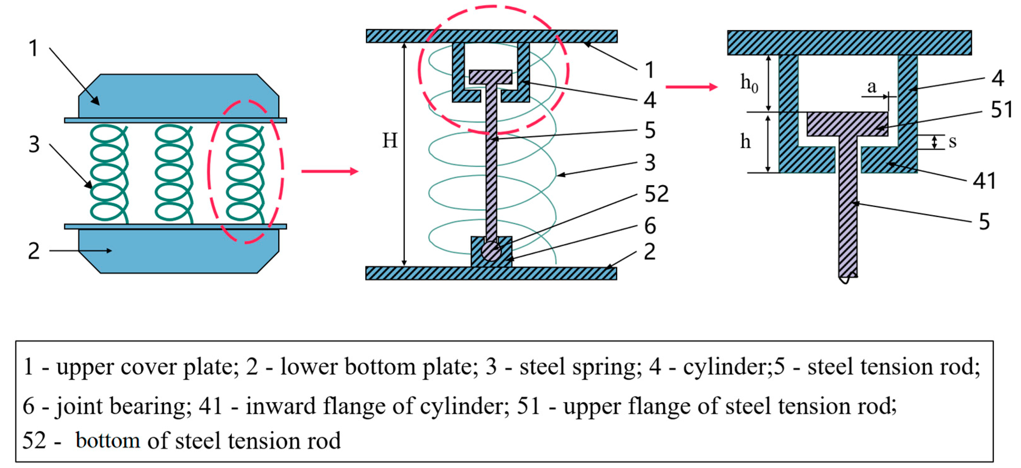
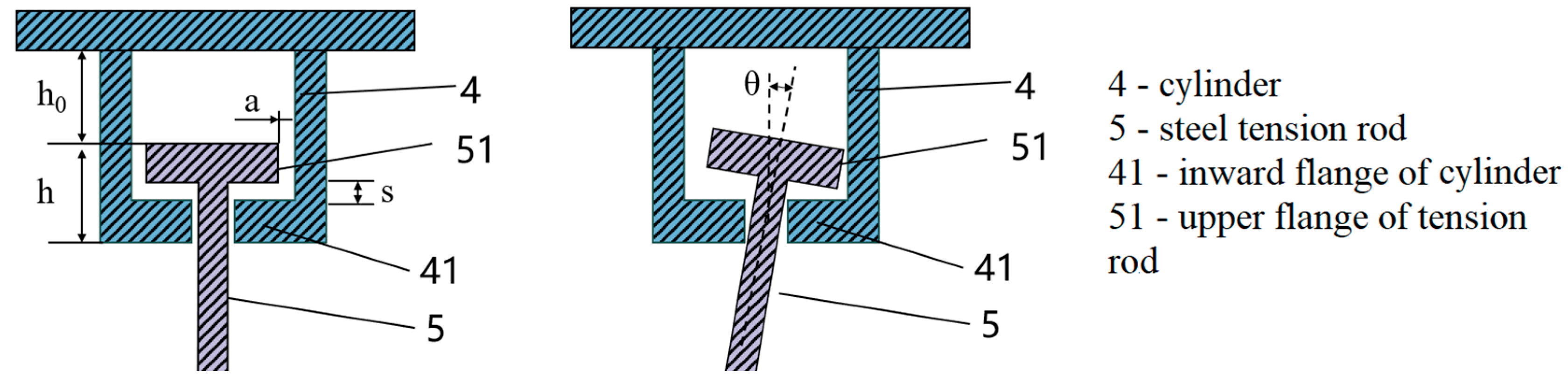
2.1. Structural Construction and Working Principle

The schematic diagram of the novel anti-rocking bearing structure is shown in Figure 1, which mainly consists of an upper cover plate, lower bottom plate, cylindrical steel spiral spring, cylinder, steel tension rods, and joint bearings. The cylinder is connected to the upper cover plate, while the joint bearing is attached to the lower base plate. The upper flange of the steel tension rods is T-shaped, whereas the lower end features a ball head structure. The lower end of the cylinder is folded inward to form an inward annular flange with a circular through-hole in the middle of the flange. The steel tie rod passes through the hole, and the T-shaped flange at the upper end of the steel tension rod is located inside the steel sleeve. The diameter of the steel tension rod flange is larger than that of the inward flange of the cylinder. The steel spring is assembled around the outer periphery of the cylinder, steel tension rods, and joint bearings.
The steel spring height between the upper cover plate and the lower bottom plate is denoted as H . The distance between the upper end of the steel tension rod and the lower end of the cylinder is represented as h . The distance between the upper flange of the steel tension rod and the upper cover plate is h 0 , and the distance between the upper flange of the steel tension rod and the inward flange of the cylinder is s . Additionally, the distance between the upper flange of the steel tension rod and the inner wall of the cylinder is denoted as a . It is important to note that H and h 0 are specific parameters of the bearing during normal usage, specifically representing the vertical deformation generated under the action of gravity loads.
The working principle of this new anti-rocking bearing is as follows: During normal usage, there is a clearance h 0 between the upper flange of the steel tension rod and the upper cover plate, as well as a clearance s between the upper flange of the steel tension rod and the lower flange of the cylinder. Importantly, the size of clearance h 0 is greater than that of clearance s . In this configuration, the steel spring assumes the responsibility of carrying all of the gravity loads of the structure, while the steel tension rod remains unburdened. The presence of these clearances enables the steel spring to oscillate freely within a certain range of vertical displacement, effectively fulfilling its intended function of isolating subway vibrations.
Under the action of earthquakes, the structure will experience a significant overturning moment. Due to the relatively low vertical stiffness of the steel spring, the compression on one side of the structure will increase, while the compression on the other side will decrease. As a result, the steel spring on the side with reduced compression will cause the cylinder to move upward in tandem with the upper cover plate. Once the displacement surpasses the distance between the upper flange of the steel tension rod and the inward flange of the cylinder (s), the upper flange of the steel tension rod will contact the inward flange of the cylinder. Consequently, the steel tension rod will begin to bear tension.
The axial tensile stiffness of the steel tension rod is significantly higher than the vertical stiffness of the steel spring. Therefore, when the steel tension rod comes into play, the vertical stiffness of the bearing increases. This, in turn, reduces the vertical displacement of the bearing and effectively achieves the anti-rocking objective. On the other hand, for the steel spring with increased compression, the larger clearance ( h 0 ) between the upper flange of the steel tension rod and the upper cover plate means that they do not come into contact. Although the steel tension rod cannot play a role, it also ensures that it will not buckle.
The presence of the clearance a between the upper flange of the steel tension rod and the inner wall of the cylinder allows for free rotation of the lower part of the steel tension rod, which is connected to the joint bearing with a spherical shape. As a result, when subject to an earthquake’s action, the bearing experiences horizontal displacement, and the steel tension rod can rotate along with it, without bearing horizontal seismic force.
Indeed, the design of this structure ensures that the presence of the steel tension rod does not impede the isolation of subway vibrations by the steel spring. Under earthquake actions, the steel tension rod not only plays an anti-rocking role but also will not be crushed or destroyed by horizontal seismic forces.
The anti-rocking bearing is improved on the basis of the original steel spring bearing. By setting the tension-only steel tension rod, the stiffness of the bearing is changed, so as to increase the anti-rocking stiffness of the structure and realize the purpose of suppressing the rocking effect. Combined with the steel spring bearing, it does not add an additional large rocking-suppression device, and the construction is convenient and the cost is lower. The anti-rocking bearing can be arranged according to the actual engineering needs, the stiffness of the steel tension rod can also be changed freely, and the arrangement is more flexible.

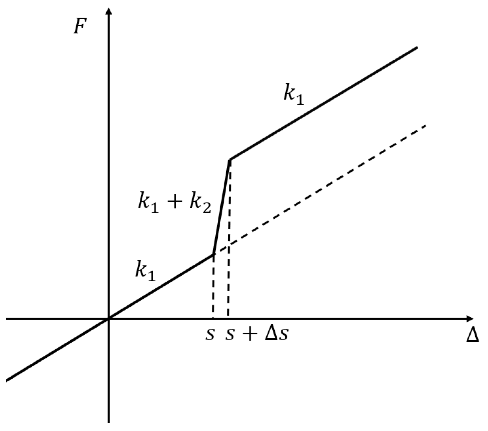
2.2. Stiffness Calculation

Figure 2 shows a schematic diagram of the force–displacement relationship for this novel anti-rocking bearing. The steel spring in the bearing is a linear elastic model, and the steel tension rod is a hysteretic model assuming the vertical stiffness k 1 of the steel spring and the axial tensile stiffness k 2 of the steel tension rod, with corresponding elastic deformation before yielding, s , and a clearance, s , between the T-shaped flange at the upper end of the steel tension rod and the lower flange of the cylinder. Assuming the vertical displacement of the bearing is Δ , the vertical stiffness, k , of the bearing is given by Equation (1) and converted to anti-rocking stiffness by Equation (2).
k = k 1 Δ < s k 1 + k 2 s < Δ < s + Δ s k 1 s + Δ s < Δ
K R = d 2 × k 1 Δ < s d 2 × k 1 + k 2 s < Δ < s + Δ s d 2 × k 1 s + Δ s < Δ
where d is the distance between the anti-rocking bearing and the center point of the structure while KR is the anti-rocking stiffness.

2.3. Design of Bearing Parameters

The design of bearing parameters mainly includes the vertical stiffness k 1 of the steel spring, the axial tensile stiffness k 2 of the steel tension rod, the clearance s between the T-shaped flange at the upper end of the steel tension rod and the lower flange of the cylinder, the clearance a between the upper end of the steel tension rod and the inner wall of the cylinder, and the distance h 0 between the upper flange of the steel tension rod and the upper cover plate.
(1) The vertical stiffness k 1 of the steel spring
The design of the vertical stiffness of the steel spring needs to consider the frequency of the isolation structure. Firstly, select a suitable frequency for the isolation structure according to the isolation target. The vertical stiffness can be calculated according to the designed isolation frequency and the designed bearing pressure by Equations (3) and (4):
f = ω 2 π = 1 2 π k 1 m
k 1 = 4 π 2 f 2 F g
where f and T are the natural frequency ( H z ) and natural period ( s ) of the isolation structure, respectively. F is the design bearing pressure ( k N ), and F = m g .
(2) The axial tensile stiffness k 2 of the steel tension rod
The axial tensile stiffness of the steel tension rod has a significant impact on the anti-rocking performance of the bearing. For a single bearing, if the steel tension rod does not yield, the load–displacement curve of new anti-rocking bearing is as shown in Figure 3a, and the axial stiffness k 2 of the steel tension rod is as shown in Equation (5):
k 2 = k 1 c k 1 s c s k 1
where c is the maximum vertical displacement of the original bearing, b is the maximum vertical displacement of the designed bearing, and s is the initial clearance of the steel tension rod.
If the steel tension rod yields under tension, assuming that its elastic deformation before yielding is s , the yield force is F y , and the axial tensile stiffness k 2 of the steel tension rod is as shown in Figure 3b if the stiffness after yielding is not considered.
F y = k 1 c k 1 b
k 2 = E k 1 c b f y l
where f y is the yield strength of the steel tension rod, E is the elastic modulus of the steel tension rod material, and l is the effective length of the steel tension rod.
The required yield force or stiffness of the steel tension rod can be obtained from Equations (6) and (7), and the cross-sectional area of the steel tension rod can be calculated. If the steel tension rod is too large, it cannot be installed inside a single steel spring. It can be installed inside multiple steel springs with the same support, arranged outside the spring, or between two springs, to ensure that the total stiffness of the steel tension rod is the same.
(3) Clearance s between the upper T-shaped flange of the steel tension rod and the inward flange of the cylinder
A certain clearance is left between the upper T-shaped flange of the steel tension rod and the inward flange of the cylinder to meet the requirements of vertical isolation of the steel spring. The clearance s needs to be greater than the maximum displacement of the subway vibration, and the maximum displacement can be obtained by the vibration analysis of the structure without the anti-rocking bearing. However, the clearance cannot be too large, so as to ensure that the steel tension rod can play a role when the bearing undergoes a small displacement and improves the anti-rocking effect. The vibration caused by the subway is micro-vibration, and it is reasonable to set the clearance to a few millimeters or a dozen millimeters.
It is important to note that the value of the clearance s corresponds to the distance between the bearing and its normal working state. During the design process, it is recommended to consider the compression of the steel spring under the gravity load as the initial step. Subsequently, the appropriate value for the clearance s can be determined based on this information.
(4) Clearance a between the upper flange of the steel tension rod and the inner wall of the cylinder
As shown in Figure 4, when the height H of the steel spring of the bearing, the distance h between the upper end of the steel tension rod and the lower end of the sleeve, and the design lateral displacement d are given, the rotation angle θ of the steel tension rod is
θ = arctan d H d H
a = h tan θ h θ = h d H
(5) Distance h 0 between the upper flange of the steel tension rod and the upper cover plate
The distance h 0 needs to be greater than the maximum negative vertical displacement of the steel spring bearing to ensure that the upper flange of the steel tension rod and the upper cover plate do not contact each other when the steel spring is maximally compressed, and to prevent buckling of the steel tension rod under compression. The vertical maximum negative displacement of the bearing can be estimated by calculating the maximum negative displacement of the structure without the anti-rocking bearing, so as to estimate the h 0 required for the layout. However, h 0 should not be too large, because the height of the bearing is limited, and the effective working length of the steel tension rod should also be guaranteed. For example, the calculated maximum negative displacement of the unarranged anti-rocking bearing structure is 15 mm, and it may be reasonable to set h 0 to 20 mm.

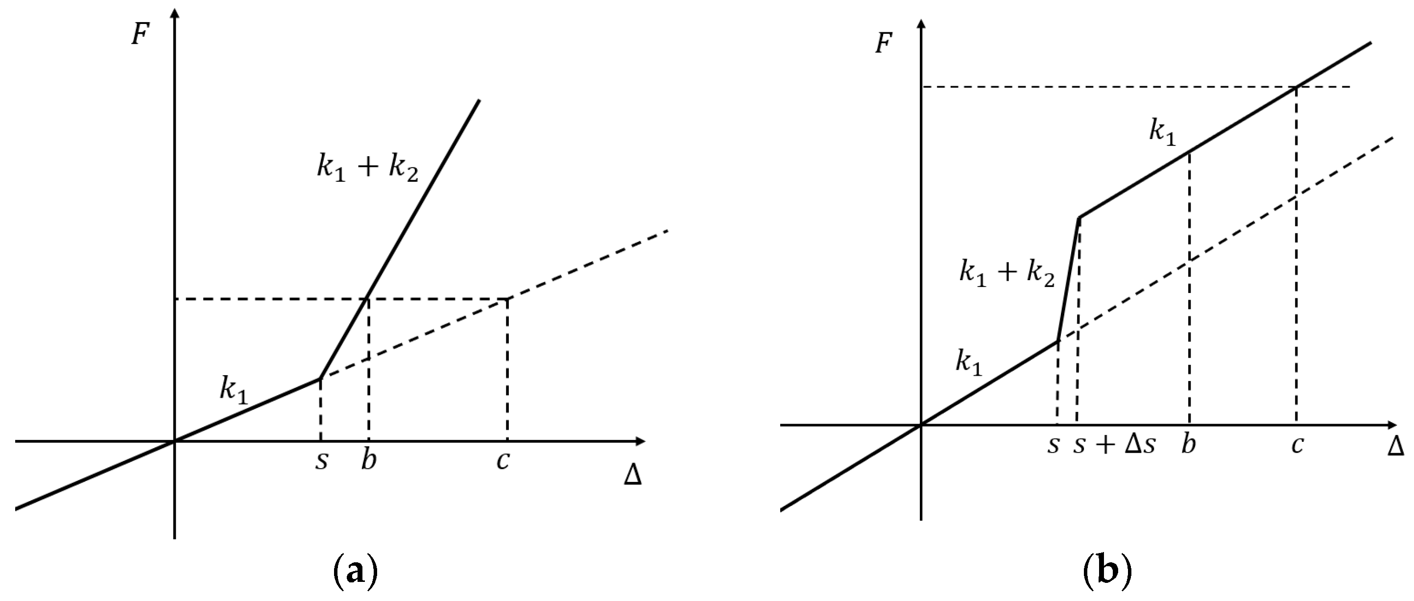
2.4. Performance Evaluation Methods

For the comprehensive performance evaluation of new anti-rocking bearings, there are two main aspects to consider:
(1) Anti-rocking effect
When a structure undergoes rocking deformation, the vertically oriented bearing will experience vertical displacement as well. The rocking angle φ of the structure is defined as the ratio of the vertical displacement difference between the two sides of the isolation layer to the structure width B [23]. The effectiveness of the new anti-rocking bearings can be evaluated based on the vertical displacement difference and the rocking angle.
(2) Maximum tension in the bearings
The incorporation of steel tension rods will result in significant tensile forces acting on the bearings during seismic events. Therefore, it is necessary to consider the anchoring of the bearings. Thus, controlling the maximum tension in each bearing within a reasonable range is important to ensure the feasibility of the design. Additionally, reducing the total tension in the bearings can minimize the usage of reinforcing bars and lower the overall cost.

3. Analysis of Anti-Rocking Effect
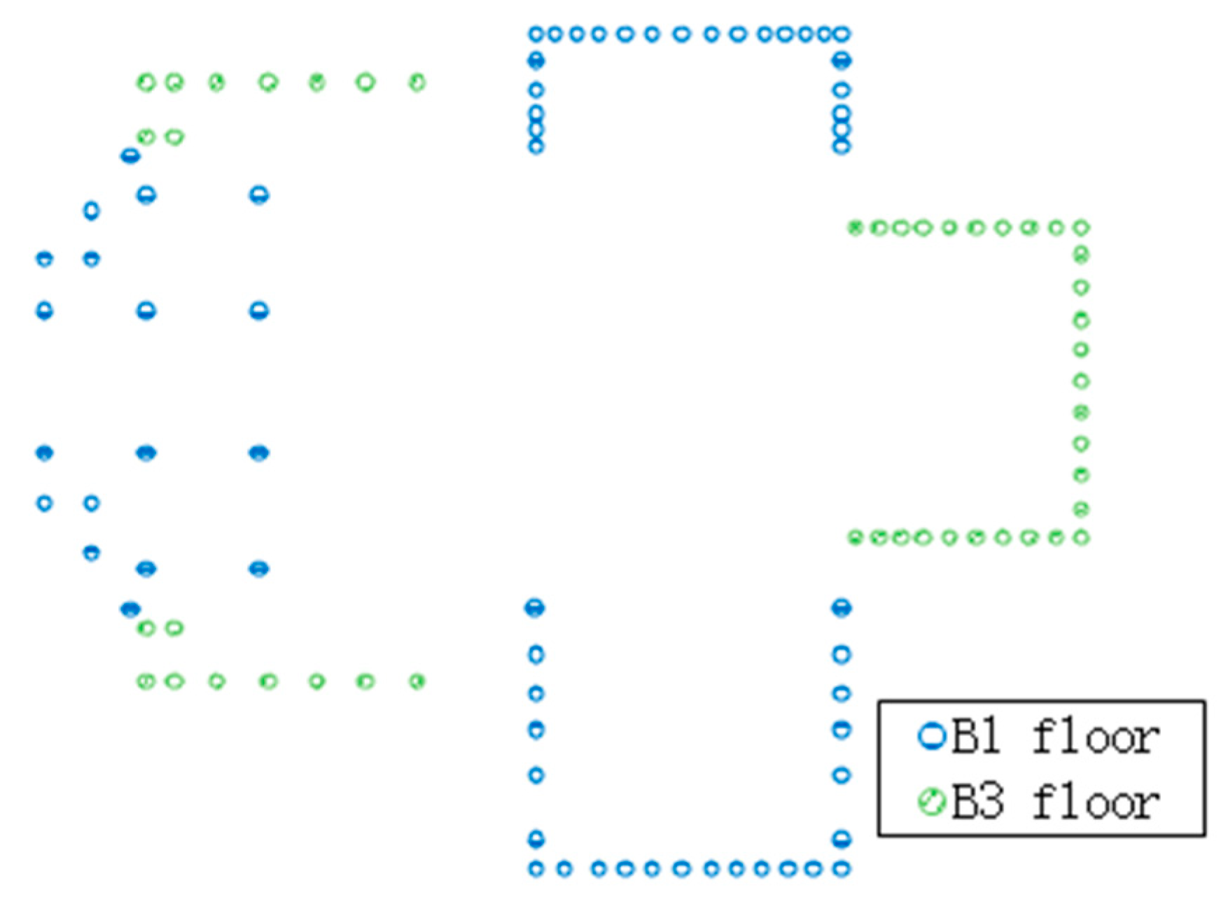
To further analyze the actual performance of the anti-rocking bearings, the bearings were subjected to a numerical model for analysis.

3.1. Analysis Model

The analysis model adopts a structural model of a theater’s vibration isolation zone (Figure 5), with a maximum length of 82.7 m in the X direction and a maximum width of 60.4 m in the Y direction. Most of the structure is located underground. The elevation of the B4 layer is −30.5 m, and the elevation of the steel beam at the top of the main stage is 31.5 m. The main structure adopts a concrete frame seismic wall structure, the thickness of the shear wall is 500~700 mm, and C40 concrete is used. The height of the beam section ranges from 600 mm to 1000 mm, and the length of the column section ranges from 500 mm to 800 mm. The large-span roof on the top of the main stage is arranged with steel beams, with a span of 24 m. The top structure of the auditorium is a steel truss with a span of 35 m.
In the seismic time–history analysis, the structure mass used is 60,325 t. The vibration isolation structure is relatively irregular, and the isolation bearings are arranged at four different elevations B1 to B4. According to the requirements of structural vibration control, a total of 298 bearings are installed. The total vertical stiffness of the 298 bearings is 1.94 × 10⁷ kN/m, and the horizontal stiffness of the bearings is taken as one-third of the vertical stiffness. The steel spring arrangement diagram is shown in Figure 6.
The software used for the analysis was SAP2000. The ordinary steel spring bearings were simulated using elastic connection elements (steel springs). Figure 7 shows the first and second modes of the structure. The first mode of the structure is the overall Y-direction rocking characteristic, and the second mode of the structure is the overall X-direction rocking. The first frequency of the structure is 1.18 Hz, and the second frequency is 1.3 Hz. Due to the arrangement of the steel springs, the structural frequency is low.
Based on the vibration isolation design, the anti-rocking bearings were arranged, and 113 steel spring bearings were replaced by anti-rocking bearings. The arrangement of the anti-rocking bearings is shown in Figure 8, and the remaining 185 steel spring bearings remained unchanged. In SAP2000, the new anti-rocking bearings were simulated using elastic connection elements (steel springs) and plastic connection elements (steel tension rods).
The seismic analysis method uses seismic time–history analysis with a seismic fortification intensity of 7 degrees and 0.1 g. The site characteristic period is 0.35 s, and three natural waves are selected: Taft earthquake record, RH3TG035, and TH035TG035. The peak acceleration of the rare earthquake is 220 cm/s2. The seismic waves in the X, Y, and Z directions are loaded, and the peak acceleration ratio of the seismic waves in each direction is 1:0.85:0.65 under the same case.
To investigate the effects of different steel tension rod parameters on the anti-rocking performance, the following two-parameter variables were considered:
(1) The initial clearance s between the T-shaped flange and the inward flange of the cylinder in the upper part of the steel tension rod, abbreviated as the initial clearance of the steel tension rod in the following text;
(2) The axial tensile stiffness k 2 of the steel tension rod.
In addition, h 0 is 30 mm, and the clearance a between the upper flange of the steel tension rod and the inner wall of the cylinder is 5 mm. The parameter settings for the calculation model under different cases are shown in Table 1.

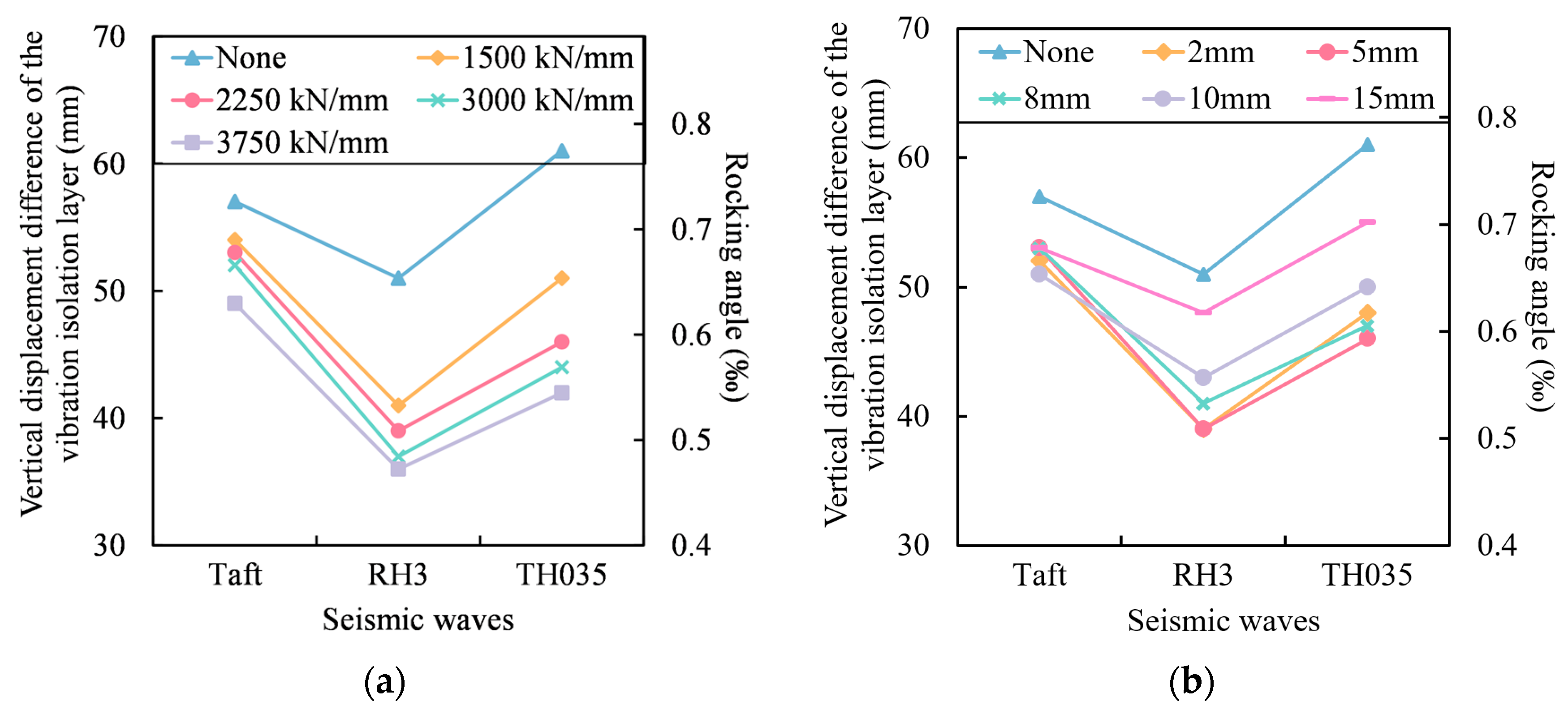
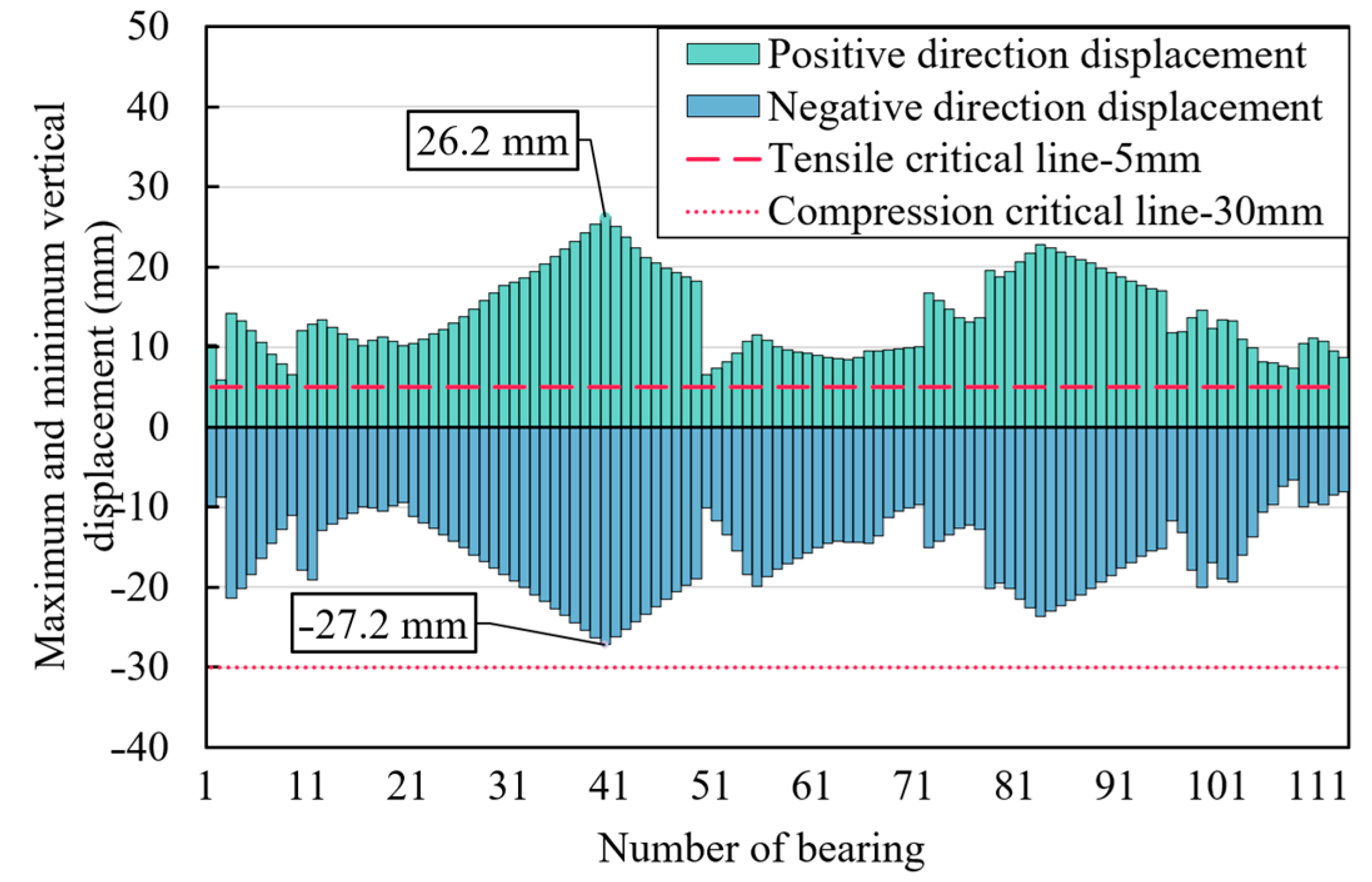
3.2. Structural Rocking Response

In this example, the bearings are uniformly distributed on the outer edge of the structure. The maximum vertical displacement difference among the bearings located at the outer edge represents the vertical displacement difference of the vibration isolation layer. The rocking angle, defined as the ratio of the vertical displacement difference of the vibration isolation layer to the width of the structure, is taken as 82.7 m.
According to Figure 9, the variation in the vertical displacement difference of the vibration isolation layer and the rocking angle of the structure with the stiffness of the steel tension rod can be observed. From Figure 9a, it can be seen that as the stiffness of the steel tension rod increases, the rocking angle of the structure continuously decreases, but the rate of decrease slows down. After the arrangement of a steel tension rod with stiffness of 2250 kN/mm, the vertical displacement differences of the vibration isolation layer were measured at 53 mm, 39 mm, and 46 mm. Moreover, the rocking angles of the structure decreased by 7%, 24%, and 25% respectively, indicating a certain anti-rocking effect. From Figure 9b, it is evident that compared to the model without the arrangement of steel tension rods, the vertical displacement differences of the vibration isolation layer reduced after the arrangement of the steel tension rods, regardless of the initial clearance size. As the initial clearance of the steel tension rod increases, the overall vertical displacement difference in the vibration isolation layer gradually increases, the rocking angle increases, and the anti-rocking effect weakens. However, considering the need for the bearing to meet the isolation requirements and production accuracy limitations, the initial clearance of the steel tension rods cannot be too small. Therefore, it is necessary to select a reasonable clearance for the steel tension rods. In cases 2-1 to 2-4, a clearance of 5 mm for the steel tension rods is more appropriate.
In addition, different seismic waves also have a significant impact on the anti-rocking effect. For example, In the case of TH035TG035 and RH3TG035, the arrangement of a 150 t steel tension rod anti-rocking bearing results in a decrease in the rocking angles of the structure by 24% and 25%, respectively. This indicates a substantial reduction in rocking motion when these seismic waves are considered. However, when exposed to the Taft earthquake record, the rocking angle of the structure only decreases by 7%. This difference in the reduction in the rocking angle compared to other waves is noteworthy.
Figure 10 is the horizontal displacement amplification factor of the vibration isolation layer. The influence of the anti-rocking bearing on the horizontal displacement is not obvious. The x-axis displacement amplification coefficient ranges from 0.97 to 1.11, and the y-axis displacement amplification coefficient ranges from 0.95 to 1.10. In most cases, the horizontal displacement is amplified, and the influence of the stiffness of the steel tension rod on the horizontal displacement is related to the seismic waves.

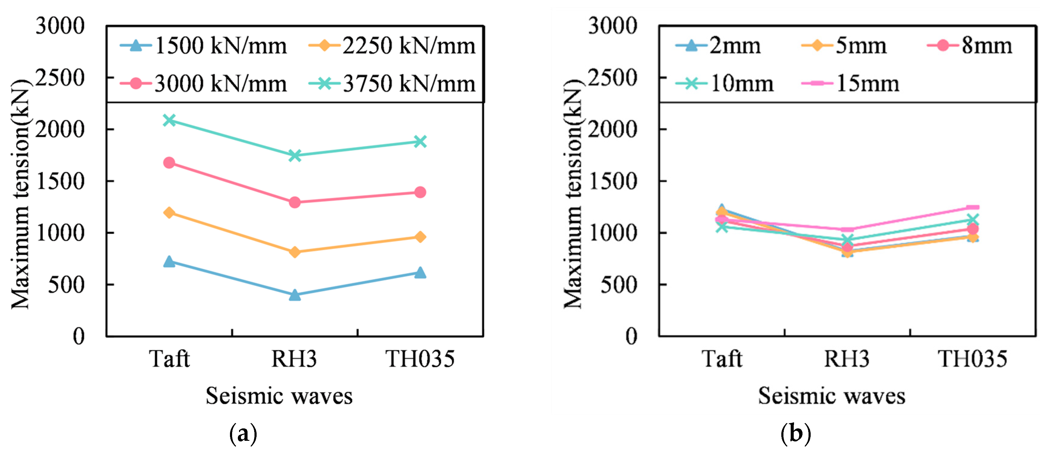
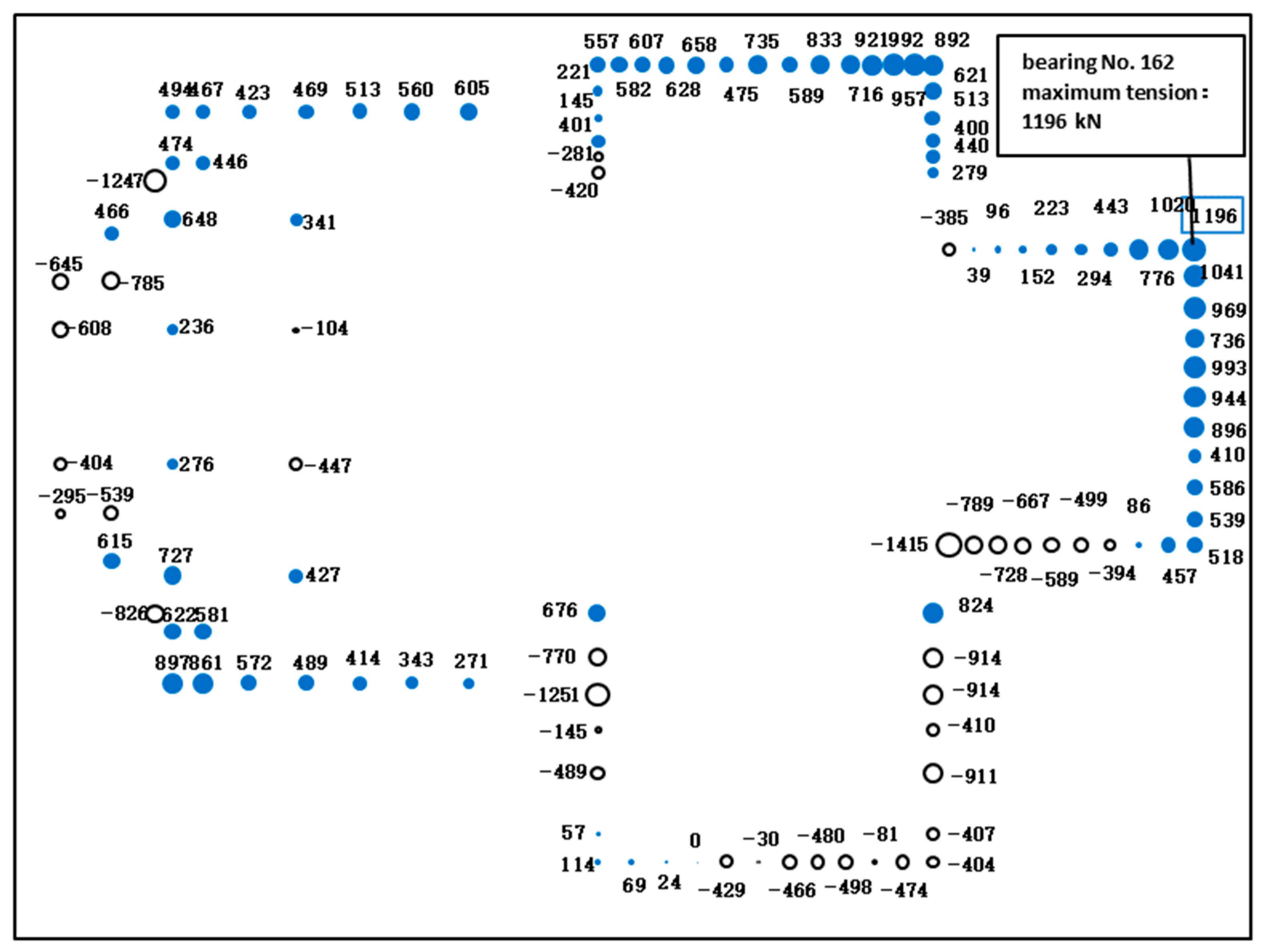
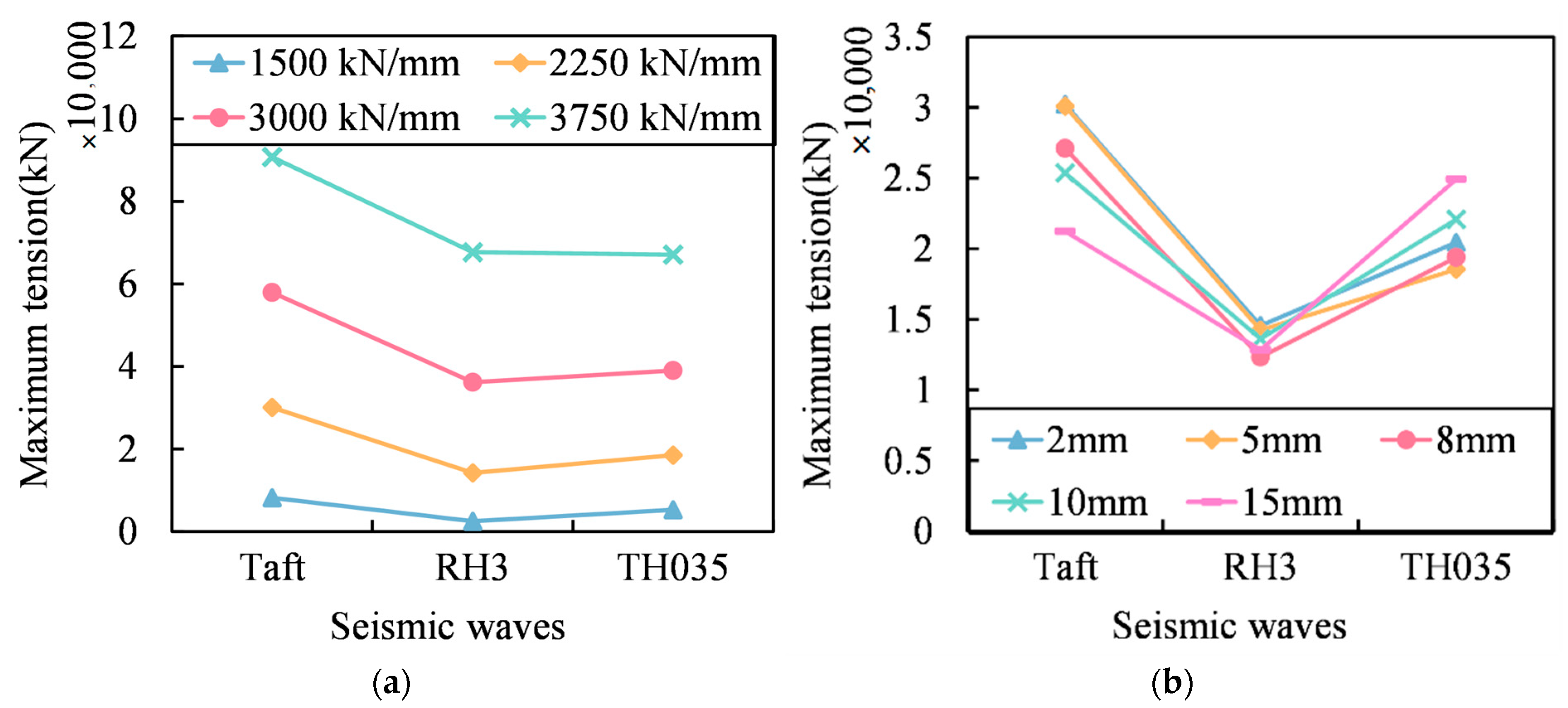
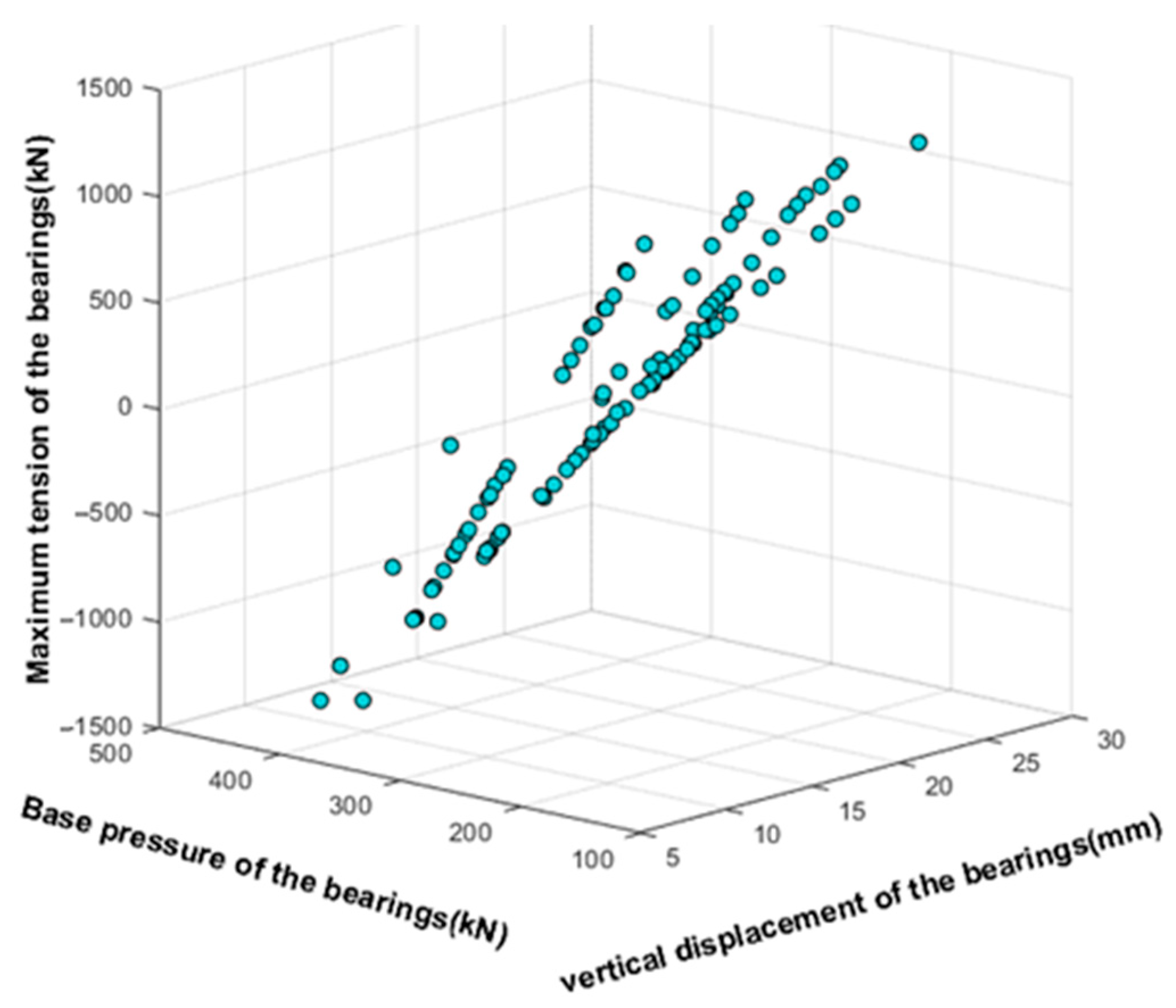
3.3. Maximum Tension

The presence of steel tension rods in the bearings introduces tension when significant displacement occurs. In order to withstand this tension, it becomes necessary to install reinforcing bars in the upper and lower piers or shear walls to enhance their resistance to tension. It is important to ensure that the tension in each individual bearing does not exceed safe limits.
Figure 11 shows a comparison of the maximum tension of a single bearing under different cases. In case 1-1, no steel tension rod is arranged, and all bearings have no tension. From the figure, it can be seen that under a certain initial clearance of the steel tension rod, the higher the stiffness of the steel tension rod, the higher the maximum tension of a single bearing, and it increases nearly linearly. Under a certain stiffness of the steel tension rod, the relationship between the maximum tension of a single bearing and the initial clearance of the steel tension rod and the seismic wave are related, such as the TH035TG035 wave and RH3TG035. As the initial clearance of the steel tension rod increases, the maximum tension of a single bearing also increases. However, the Taft earthquake record first decreases and then increases.
Figure 12 presents the maximum tension of each bearing under the Taft earthquake wave in case 2-2 (the stiffness of the steel tension rod is 2250 kN/mm, with an initial clearance of 5 mm), in the form of a bubble chart (solid blue circles represent the bearing under tension, and empty circles represent the bearing under compression, where tension is positive and compression is negative, expressed in tons). From the figure, it can be seen that the bearings located far away from the center of the structure generally have higher tension. Bearing No. 162 has the greatest tension, with a maximum value of 1196 kN. Moreover, only some bearings are under tension, while others remain under compression.
However, the overall compression of the bearing does not mean that the steel tension rod does not play a role. Figure 13 shows the maximum positive and negative displacements of each bearing in the vertical direction under the Taft seismic wave of working condition 2-2 (steel tension rod stiffness 2250 kN/mm, initial clearance 5 mm). The displacement is positive upward and negative downward. The tensile critical displacement and compressive critical displacement of the steel tension rod in the bearing are also marked in the figure. The critical tension displacement is the initial clearance of the steel tension rod s , which is 5 mm, and the critical compression displacement is the distance between the upper flange of the steel tension rod and the upper cover plate h 0 , which is 30 mm. When the bearing displacement is lower than the steel tension rod’s critical compression line, the steel tension rod will be compressed. It can be seen from the figure that, under this case, the steel tension rods of all bearings have reached the tensile state and have not reached the compressive state, so the steel tension rods will not buckle, and the same is true for other cases.
Figure 14 shows a comparison of the total tension of the bearings under different cases. In case 1-1, no steel tension rod is arranged, and the total tension of all bearings is zero. From the figure, it can be seen that under a certain initial clearance of the steel tension rod, the greater the stiffness of the steel tension rod, the higher the total tension of the bearings, and the increasing trend becomes tighter. Under a certain stiffness of the steel tension rod, the relationship between the total tension of the bearings and the initial clearance of the steel tension rod and the seismic wave is related. With the increase in the initial clearance, the change trends of the total tension of the bearings are different.

3.4. Hysteretic Performance of the Bearings

Figure 15 and Figure 16 show the vertical hysteresis curves of bearings No. 162 and No. 167, respectively. Due to the fact that the steel tension rods in the new anti-rocking bearing only experience tension and not compression, their hysteresis curves exhibit a “flag” shape. In this analysis, bearing No. 162 has the maximum vertical displacement, thus generating a large tension of 1194 kN, 810 kN, and 840 kN under the three earthquake waves, respectively. Bearing No. 167 has a smaller vertical displacement and generates a maximum tension of 220 kN under the Taft earthquake wave, while none of the other earthquake waves cause tension in this bearing.
Since the steel tension rod is located inside the spring and its length cannot be too long, the steel tension rod’s length is taken as l = 300   mm , and the elastic deformation before yielding is only 0.66 mm. Although it can yield early and dissipate energy, it will leave a large residual deformation. Moreover, the steel tension rod in the new anti-rocking bearing only undergoes tensile stress, and residual deformation will continue to accumulate. Assuming a set initial clearance of 5 mm for the steel tension rod, in the steel spring bearing, the upper end of the steel tension rod is only required to move upward by 5 mm to function. After the first yielding occurs, the residual deformation causes the clearance to be greater than 5 mm, which delays the function of the steel tension rod. The residual deformation continues to accumulate, ultimately resulting in an increase in the initial clearance and a gradual weakening of the function over time.

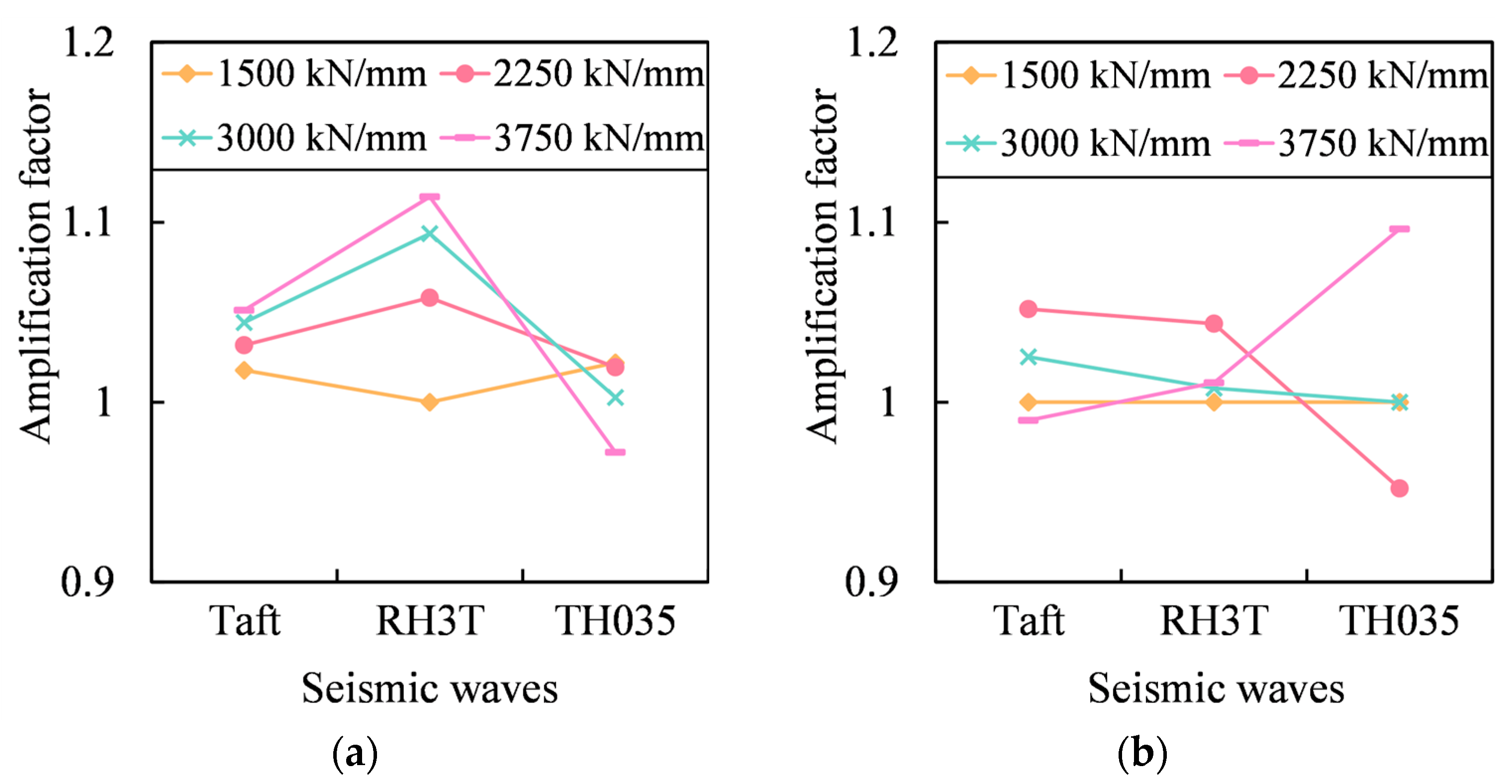
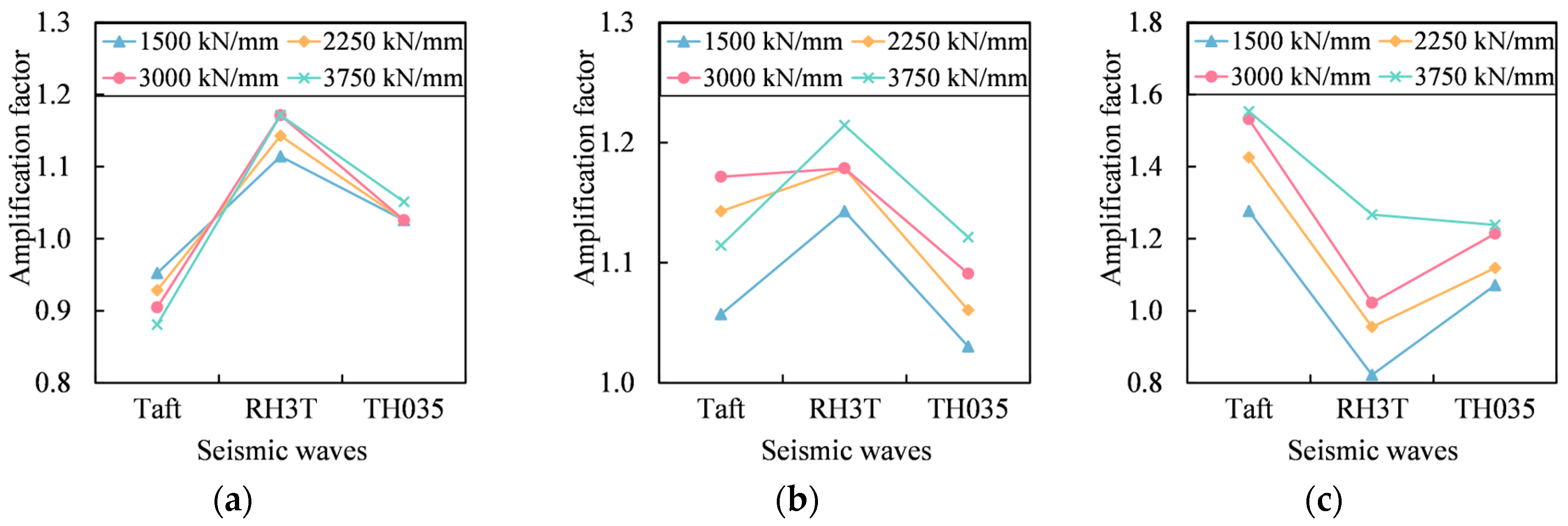
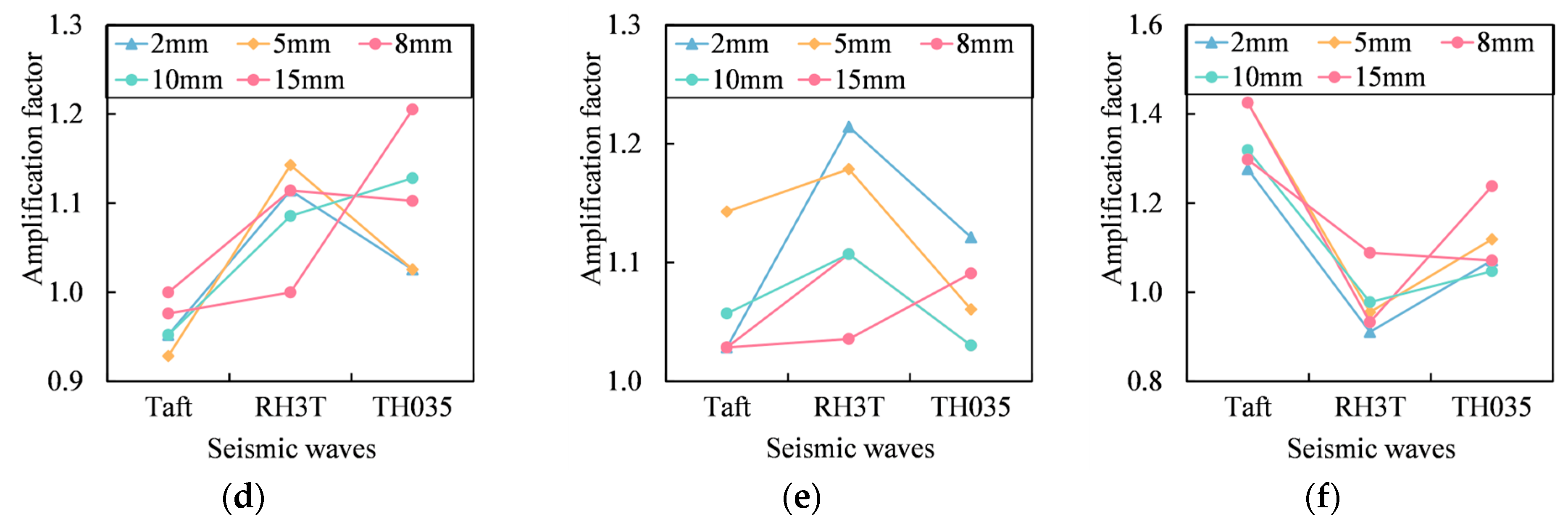
3.5. Structural Acceleration Response

Figure 17 illustrates the amplification factor of structural acceleration. When anti-rocking bearings are employed in the structure, the acceleration is amplified under the majority of operating conditions. The amplification factor ranges from 0.82 to 1.55. As the stiffness of the steel tension rods increases, the vertical acceleration of the structure is also amplified, while the amplification trend of the horizontal x-axis and y-axis is not obvious. There is no evident pattern observed for the acceleration with an increasing initial clearance of the steel tension rods.

3.6. Selection of Steel Tension Rod Stiffness

The stiffness of the steel tension rod has a strong correlation with the anti-rocking effect and the maximum tension of the bearing (Figure 9 and Figure 11). Part of the bearing will experience tension after adding the steel tension rod. To prevent the upper and lower columns from detaching from the bearing, reinforcement bars should be arranged on the upper and lower columns. However, the tensile strength of the reinforcement bars is limited. Therefore, it is important to ensure that the maximum tension in each individual bearing is not too high and does not exceed the design’s maximum tension requirement. Setting the stiffness of steel tension rods reasonably is particularly important.
Figure 18 shows the relationship between the maximum tension of the bearing, the vertical displacement of the bearing, and the reference pressure of the bearing under the Taft seismic wave of case 1-4 (steel tension rod stiffness 3000 kN/mm, initial clearance 5 mm). The reference pressure of the bearings refers to the pressure that the bearings bear in normal cases. From the graph, it can be seen that the maximum tension of the bearing is positively correlated with the vertical displacement and negatively correlated with the reference pressure of the bearing.
The stiffness of steel tension rods in anti-rocking bearings should be selected based on the reference pressure of the bearing and the maximum tension of the designed bearing. First, the maximum tension of the designed bearing and the reference pressure of the bearing should be determined according to the design requirements, and an appropriate steel tension rod should be selected for calculation. The stiffness of the steel tension rod should be adjusted according to the size of the bearing reaction force. Since actual structural bearings are more numerous and subject to more complex stresses, multiple adjustments may be necessary.
As a parameter of the result, the vertical displacement of the bearing is affected by the stiffness of the steel tension rod, the reference pressure of the bearing, and the maximum tension of the designed bearing, and it cannot be directly controlled.

4. Finite Element Simulation of Bearing

In order to further understand the mechanical characteristics of the bearing, the static tensile simulation of the bearing was carried out using the finite element analysis software ANSYS 2021.

4.1. Material of Steel Tension Rods

The material of the steel tension rods is high-ductility special steel, which has high yield strength and good ductility. The elongation after fracture can reach 67.8% (Table 2). The mechanical characteristic curve of special steel is shown in Figure 19. Special steel has high ductility and no obvious necking after fracture. From the characteristic curve, it can be seen that with the increase in deformation, the stress of the steel increases. In the range of allowable elongation, the necking phenomenon can be ignored.

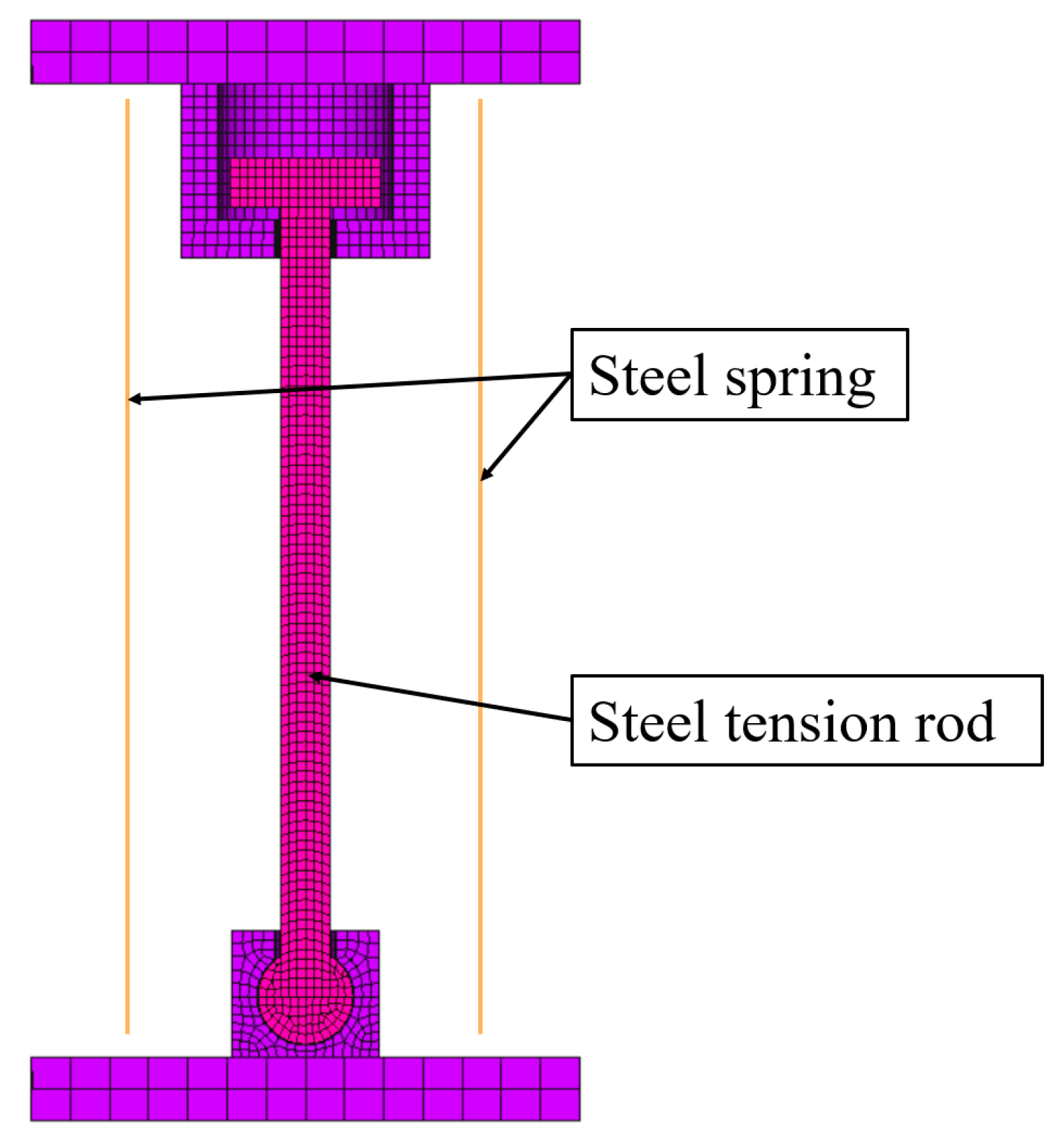
4.2. Finite Element Model

Considering that the spring bearing is composed of spring components with the same parameters in parallel, ignoring the interaction between the spring components, it can be approximated that the mechanical performance parameters of the spring support are the sum of the spring components, so the finite element analysis model can only establish a single spring model. Taking bearing No. 162 in the above section’s analysis model as an example, the vertical stiffness of the spring is 52,600 kN/m, and the total stiffness of the steel tension rod is set to 2250 kN/mm. It is assumed that the bearing is composed of 12 independent springs. The vertical stiffness of a single spring is 4383 kN/m, and the stiffness of a single steel tension rod is 188,926 kN/m. Based on these data, a finite element analysis model was established.
The total height of the finite element model bearing is H 0 = 391 mm, the net length of the steel tension rod is 300 mm, and the radius is 9.61 mm. The thickness of the upper flange of the steel tension rod is 20 mm, the radius is 30 mm, the gap between the flange of the steel tension rod and the inner flange of the cylinder is s = 5 mm, the gap with the side wall of the cylinder is a = 5 mm, and the gap with the upper cover plate is = 30 mm; the thickness of the side wall and the inward flange of the cylinder is 15 mm. The radius of the joint bearing and the steel tension rod is 19.1 mm, and the radius of the spherical support shell is 19.6 mm.
In the software, the steel spring is modeled by the spring element combin14, the steel tension rod and other components are modeled by the solid model, and the steel tension rod material is selected by the multi-linear elastic model. The elastic modulus is 195 × 103 MPa, the yield strength is 430 MPa, and the post-yield strength of the steel rod is not considered (that is, the post-yield stiffness is 0). The yield strength of the remaining parts is 345 MPa. Contact conditions are established between the steel rod and the ball hinge support as well as the cylinder, and the finite element analysis model is shown in Figure 20. For the tensile simulation, static displacement loading is applied. The upper cover plate is loaded step by step to move upward by 20 mm, and the analysis results are observed.

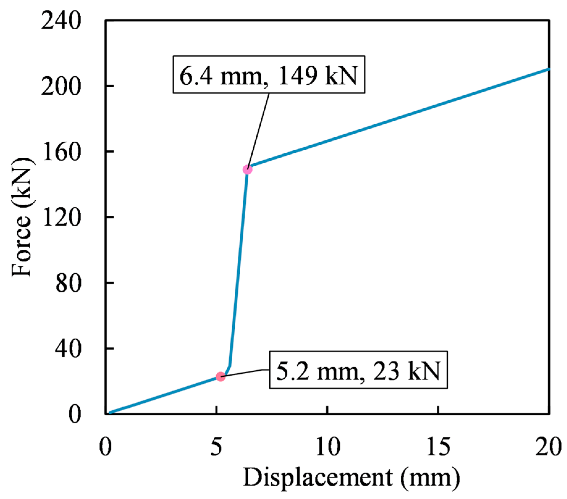
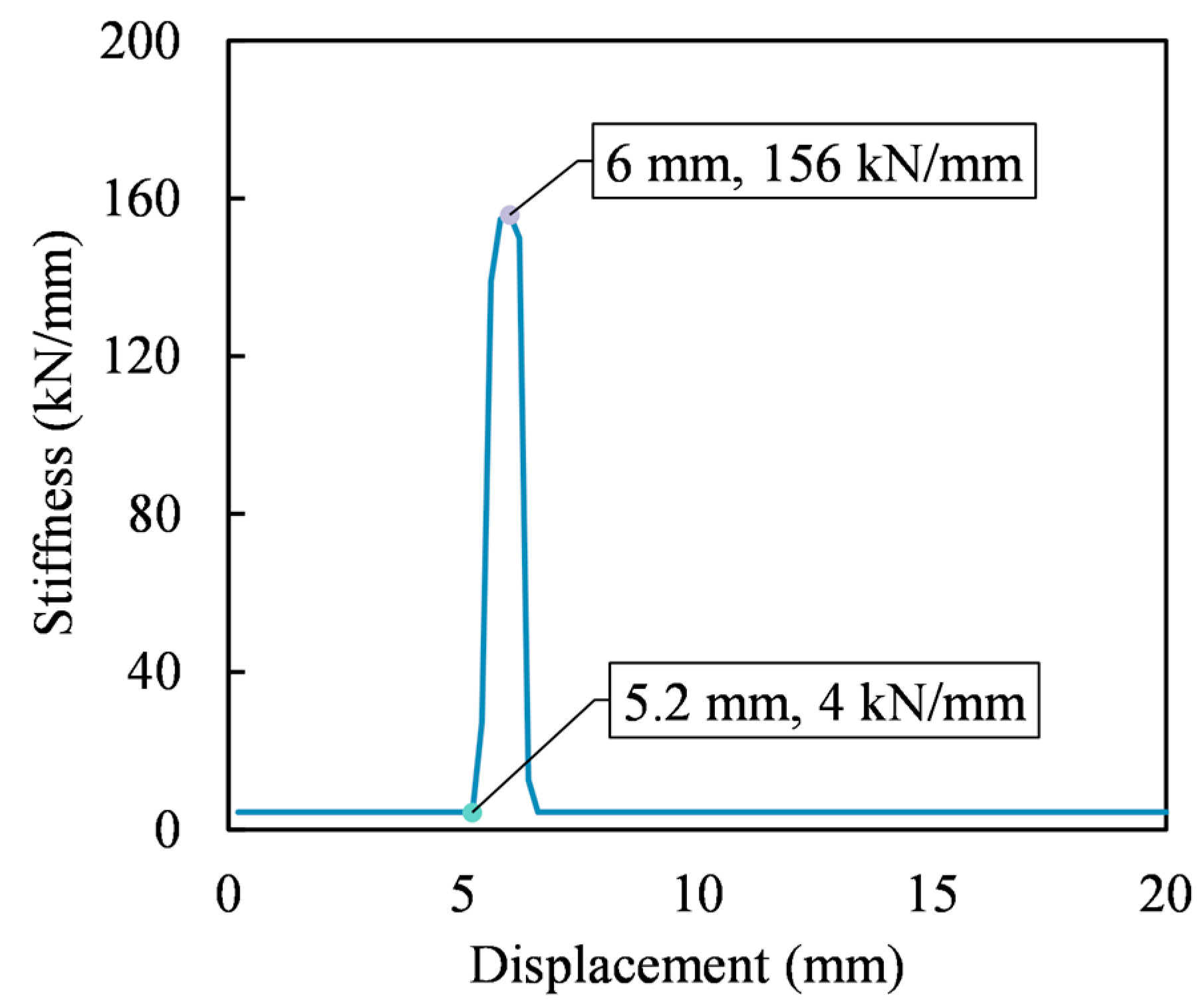
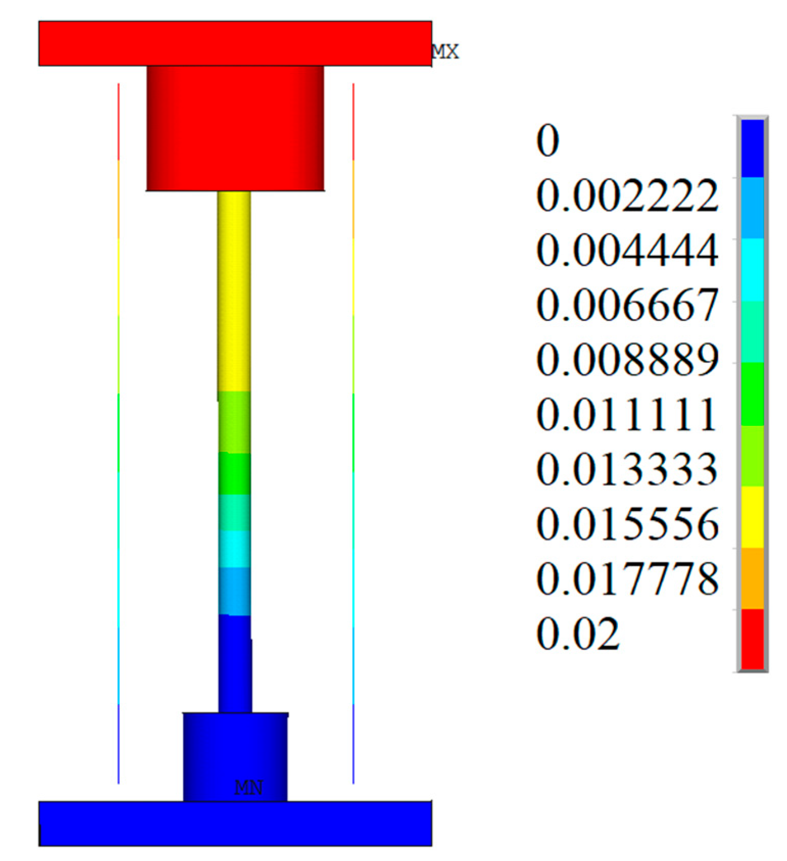
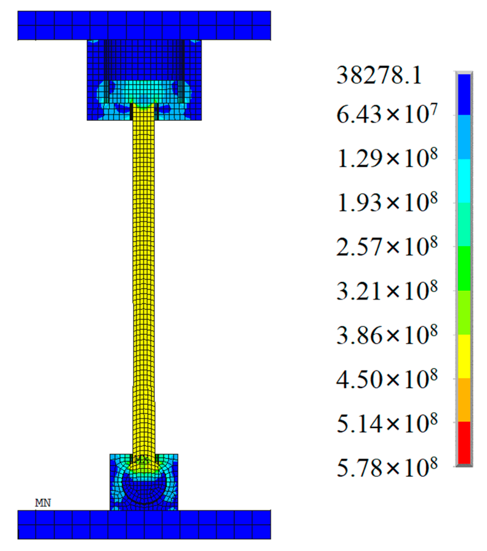
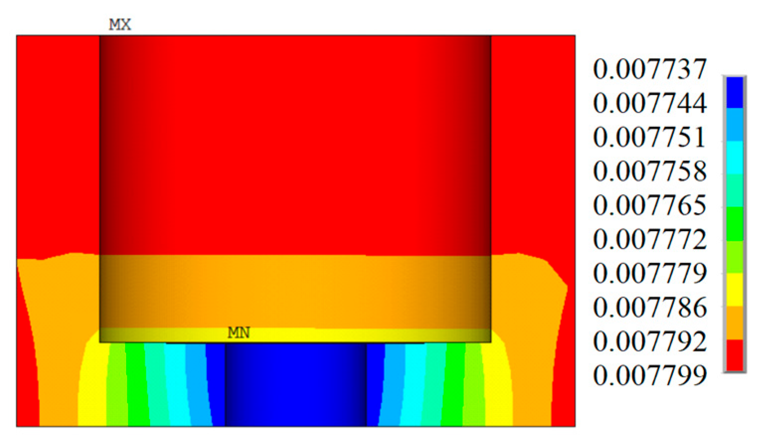
4.3. Modeling Results

The bearing’s force–displacement curve is shown in Figure 21, and the bearing’s stiffness–displacement curve is shown in Figure 22, which is essentially consistent with the force–displacement curve in Figure 21. When the displacement is 5.2 mm, the steel tension rod begins to work, which may be caused by the gap between the ball hinges of the steel tension rod.
Figure 23 is the result of bearing displacement, and Figure 24 is the result of element stress under 20 mm deformation. It can be seen that the steel tension rod reaches the yield state under 20 mm deformation, and the maximum stress is 430 MPa, but there is no obvious necking phenomenon, which is more in line with the material characteristics of the special steel itself. Figure 25 shows the stress result of the cylinder under 20 mm deformation. The maximum stress is 235 MPa, which is located at the connection between the inward flange and the side wall and does not reach the yield state. From the displacement results of the steel sleeve in Figure 26, it can be seen that the lower flange does not deform and will not bring a large stiffness change to the support. Figure 27 is the stress result of the joint bearing under 20 mm deformation. The contact area of the contact position with the steel tension rod is small, and the stress is large, so special strengthening is needed here.
From the above simulation analysis results, it can be seen that the mechanical properties of the bearing are essentially the same as the theoretical analysis results. For the cylinder and the joint bearing, it is necessary to calculate and take certain structural measures to ensure their strength and stiffness.

5. Conclusions

This paper presents an analysis of a new type of anti-rocking bearing, and we obtained the following main conclusions:
(1) The structure of the newly designed anti-rocking support system reduces both the vertical displacement difference of the isolation layer and the structural rocking angle under seismic action, achieving a certain anti-rocking effect. However, it may lead to a significant increase in tensile force in the support system.
(2) The anti-rocking effect of the bearing improves as the stiffness of the steel tension rods increases, resulting in larger maximum tension values for individual bearings and total bearing tension. Similarly, a smaller initial clearance of the steel tension rods enhances the anti-rocking effect of the bearing. It is crucial to consider the steel spring isolation requirements when selecting the clearance of the steel tension rods.
(3) The new anti-rocking bearing does not impede the horizontal displacement of the structure during seismic events. Structures equipped with the new anti-rocking bearing experience an amplification of acceleration under most operational conditions, with an amplification factor ranging from 0.82 to 1.55. The performance of the new anti-rocking bearing may exhibit significant variations across different seismic waves.
(4) The stiffness of the steel tension rods should be determined based on the reference pressure of the bearing and the maximum tension of the bearing. Multiple adjustments may be necessary to suit the actual placement of the structure.
(5) The material used for the steel tension rods is special steel. Through the finite element simulation of the bearing, the mechanical properties of the bearing were found to be essentially the same as the theoretical analysis results. For the cylinder and the joint bearing, certain structural measures need to be taken to ensure their strength and stiffness.

Author Contributions

Conceptualization, L.B.; Methodology, Y.Y.; Software, Y.Y. and F.K.; Resources, L.B.; Data curation, Y.Y.; Writing—original draft, F.K.; Supervision, Z.M.; Funding acquisition, Z.M. All authors have read and agreed to the published version of the manuscript.

Funding

This research was funded by the Fundamental Research Funds for the Central Universities (Grant No. FRF-TP-22-117A1) and the Key Laboratory of Urban Security and Disaster Engineering of the Ministry of Education (Grant No. 2024B07).

Data Availability Statement

Data is contained within the article.

Conflicts of Interest

The authors declare no conflict of interest.

References

  1. Warn, G.P.; Ryan, K.L. A review of seismic isolation for buildings: Historical development and research needs. Buildings 2012, 2, 300–325. [Google Scholar] [CrossRef]
  2. Zhang, C.; Ali, A. The advancement of seismic isolation and energy dissipation mechanisms based on friction. Soil Dyn. Earthq. Eng. 2021, 146, 106746. [Google Scholar] [CrossRef]
  3. Zhuang, P.; Zhao, W.; Yang, T.Y. Seismic protection of a single-layer spherical lattice shell structure using a separated three-dimensional isolation system. Soil Dyn. Earthq. Eng. 2023, 172, 108026. [Google Scholar] [CrossRef]
  4. Zhuang, P.; Wei, L.; Wang, W.; Han, M. Feasibility evaluation of pre-pressed spring devices for vertical isolation of single-layer spherical lattice shell structures. Soil Dyn. Earthq. Eng. 2022, 158, 107308. [Google Scholar] [CrossRef]
  5. Yong-Chul, K.; Xue, S.; Zhuang, P.; Zhao, W.; Li, C. Seismic isolation analysis of FPS bearings in spatial lattice shell structures. Earthq. Eng. Eng. Vib. 2010, 9, 93–102. [Google Scholar] [CrossRef]
  6. Demetriades, G.F.; Constantinou, M.C.; Reinhorn, A.M. Study of wire rope systems for seismic protection of equipment in buildings. Eng. Struct. 1993, 15, 321–334. [Google Scholar] [CrossRef]
  7. Pellecchia, D.; Vaiana, N.; Spizzuoco, M.; Serino, G.; Rosati, L. Axial hysteretic behaviour of wire rope isolators: Experiments and modelling. Mater. Des. 2023, 225, 111436. [Google Scholar] [CrossRef]
  8. Eltahawy, W.; Ryan, K.L.; Cesmeci, S.; Gordaninejad, F. Parameters Affecting Dynamics of Three-Dimensional Seismic Isolation. J. Earthq. Eng. 2018, 25, 730–755. [Google Scholar] [CrossRef]
  9. Politopoulos, I.; Moussallam, N. Horizontal floor response spectra of base-isolated buildings due to vertical excitation. Earthq. Eng. Struct. Dyn. 2012, 41, 587–592. [Google Scholar] [CrossRef]
  10. Pourmasoud, M.M.; Lim, J.B.; Hajirasouliha, I.; McCrum, D. Multi-directional base isolation system for coupled horizontal and vertical seismic excitations. J. Earthq. Eng. 2022, 26, 1145–1170. [Google Scholar] [CrossRef]
  11. Zhao, Z.; Wang, Y.; Hu, X.; Weng, D. Seismic performance upgrading of containment structures using a negative-stiffness amplification system. Eng. Struct. 2022, 262, 114394. [Google Scholar] [CrossRef]
  12. Liu, W.; Tian, K.; Wei, L.; He, W.; Yang, Q. Earthquake response and isolation effect analysis for separation type three-dimensional isolated structure. Bull. Earthq. Eng. 2018, 16, 6335–6364. [Google Scholar] [CrossRef]
  13. Kageyama, M.; Iba, T.; Somaki, T.; Hino, H.; Umeki, K. Development of cable reinforced 3-dimensional base isolation air spring. In Proceedings of the ASME Pressure Vessels and Piping Conference, Vancouver, BC, Canada, 5–9 August 2002. [Google Scholar]
  14. Eltahawy, W.; Ryan, K.; Cesmeci, S.; Gordaninejad, F. Displacement/velocity-based control of a liquid spring-MR damper for vertical isolation. Struct. Control. Health Monit. 2019, 26, e2363. [Google Scholar] [CrossRef]
  15. Cesmeci, S.; Gordaninejad, F.; Ryan, K.L.; Eltahawy, W. A liquid spring–magnetorheological damper system under combined axial and shear loading for three-dimensional seismic isolation of structures. J. Intell. Mater. Syst. Struct. 2018, 29, 3517–3532. [Google Scholar] [CrossRef]
  16. Chen, Z.; Ding, Y.; Shi, Y.; Li, Z. A vertical isolation device with variable stiffness for long-span spatial structures. Soil Dyn. Earthq. Eng. 2019, 123, 543–558. [Google Scholar] [CrossRef]
  17. Xu, H.; He, W.; Zhang, L.; Liu, W. Shaking table test of a novel Three-dimensional seismic isolation system with inclined rubber bearings. Eng. Struct. 2023, 293, 116609. [Google Scholar] [CrossRef]
  18. Dai, K.; Yang, Y.; Li, T.; Ge, Q.; Wang, J.; Wang, B.; Chen, P.; Huang, Z. Seismic analysis of a base-isolated reinforced concrete frame using high damping rubber bearings considering hardening characteristics and bidirectional coupling effect. Structures 2022, 46, 698–712. [Google Scholar] [CrossRef]
  19. Wu, D.; Xiong, Y.; Yang, Z. Numerical and experimental study of mechanical behaviors of the steel-confined rubber bearing. Constr. Build. Mater. 2022, 352, 128900. [Google Scholar] [CrossRef]
  20. Zhang, H.; Liang, X.; Gao, Z.; Zhu, X. Seismic performance analysis of a large-scale single-layer lattice dome with a hybrid three-directional seismic isolation system. Eng. Struct. 2020, 214, 110627. [Google Scholar] [CrossRef]
  21. Zhang, C.-X.; Nie, G.-B.; Dai, J.-W.; Liu, K.; Zhi, X.-D.; Ma, H.-H. Seismic isolation research on a double-layer lattice structure using shaking table tests. Int. J. Steel Struct. 2019, 19, 1237–1248. [Google Scholar] [CrossRef]
  22. Han, Q.; Jing, M.; Lu, Y.; Liu, M. Mechanical behaviors of air spring-FPS three-dimensional isolation bearing and isolation performance analysis. Soil Dyn. Earthq. Eng. 2021, 149, 106872. [Google Scholar] [CrossRef]
  23. Dong, W.; Shi, Y.; Wang, Q.; Wang, Y.; Yan, J.-B. Development of a long-period vertical base isolation device with variable stiffness for steel frame structures. Soil Dyn. Earthq. Eng. 2023, 164, 107638. [Google Scholar] [CrossRef]
Figure 1. Schematic diagram of the new anti-rocking bearing structure.
Buildings 14 01645 g001
Figure 2. Load–displacement curves of the new anti-rocking bearing.
Buildings 14 01645 g002
Figure 3. Load–displacement curves of the new anti-rocking bearing: (a) Steel tension rods do not yield. (b) Steel tension rods yield.
Buildings 14 01645 g003
Figure 4. Partial structural diagram of a novel bearing.
Buildings 14 01645 g004
Figure 5. Calculation model: (a) Perspective view. (b) Front view. (c) East–west section view. (d) North–south section map.
Buildings 14 01645 g005
Figure 6. Layout of steel springs.
Buildings 14 01645 g006
Figure 7. Mode of structure: (a) First-order vibration mode. (b) Second-order vibration mode.
Buildings 14 01645 g007
Figure 8. Layout of steel tension rods.
Buildings 14 01645 g008
Figure 9. Variation in the vertical displacement difference of the vibration isolation layer and the rocking angle: (a) Various stiffnesses of steel tension rods. (b) Various initial clearances of steel tension rods.
Buildings 14 01645 g009
Figure 10. Horizontal displacement amplification factor: (a) X-axis. (b) Y-axis.
Buildings 14 01645 g010
Figure 11. Maximum tension of a single bearing: (a) Various stiffnesses of steel tension rods. (b) Various initial clearances of steel tension rods.
Buildings 14 01645 g011
Figure 12. Maximum tension of bearings.
Buildings 14 01645 g012
Figure 13. Maximum and minimum vertical displacement.
Buildings 14 01645 g013
Figure 14. Total tension of the bearings: (a) Various stiffnesses of steel tension rods (b) Various initial clearances of steel tension rods.
Buildings 14 01645 g014
Figure 15. Vertical hysteretic curves of bearing No. 162: (a) Taft. (b) RH3TG035. (c) TH035TG035.
Buildings 14 01645 g015
Figure 16. Vertical hysteretic curves of bearing No. 167: (a) Taft. (b) RH3TG035. (c) TH035TG035.
Buildings 14 01645 g016
Figure 17. Acceleration amplification factor: (a) X-axis. (b) Y-axis. (c) Vertical. (d) X-axis. (e) Y-axis. (f) Vertical.
Buildings 14 01645 g017aBuildings 14 01645 g017b
Figure 18. Relationship between the maximum tension of the bearing, the vertical displacement of the bearing, and the reference pressure of the bearing.
Buildings 14 01645 g018
Figure 19. Mechanical characteristic curve of special steel.
Buildings 14 01645 g019
Figure 20. Section of finite element analysis model.
Buildings 14 01645 g020
Figure 21. Bearing force–displacement curve.
Buildings 14 01645 g021
Figure 22. Stiffness–displacement curve of the bearing.
Buildings 14 01645 g022
Figure 23. Element displacement results.
Buildings 14 01645 g023
Figure 24. Element stress results.
Buildings 14 01645 g024
Figure 25. Stress results of the cylinder.
Buildings 14 01645 g025
Figure 26. Displacement results of the cylinder.
Buildings 14 01645 g026
Figure 27. Stress results of the joint bearing.
Buildings 14 01645 g027
Table 1. Analysis cases.
CasesVibration Isolation Bearing TypeStiffness of Steel Tension Rod
/(kN/mm)
Tonnage of Steel Tension Rod/TonInitial Clearance of Steel Tension Rod/mm
1-1Steel Spring Bearing---
2-1New Anti-Rocking Bearing15001005
2-22250150
2-33000200
2-43750250
3-1New Anti-Rocking Bearing22501502
3-25
3-38
3-410
3-515
Note: All of the cases include these three seismic waves: Taft earthquake record, RH3TG035, and TH035TG035.
Table 2. Comparison of physical and mechanical properties of steel.
Steel CategorySteel Yield Strength/MPaUltimate Tensile Strength/MPaElongation after Fracture/%Elastic Modulus
(GPa)
Remarks
Special Steel438.1994.067.8195Measured value
Q235B235375~460>26206Different plate thickness, the performance is different
Disclaimer/Publisher’s Note: The statements, opinions and data contained in all publications are solely those of the individual author(s) and contributor(s) and not of MDPI and/or the editor(s). MDPI and/or the editor(s) disclaim responsibility for any injury to people or property resulting from any ideas, methods, instructions or products referred to in the content.

