Abstract
The integration of laser scanning technology and Building Information Modelling (BIM) processes offers a transformative approach to managing the complexities in live construction projects. This paper aims to explore the significant impacts of incorporating laser scanning and BIM on construction projects in terms of as-built models, information management, and overall project performance utilising case study analysis of a building that was not BIM-based. The research scope is defined by the need to investigate the integration of laser scanning and BIM in live construction projects. It details the data acquisition process, challenges encountered due to site obstructions, and the methodologies employed for spatial modelling procedures. Key findings reveal that such integration can significantly enhance the accuracy of data collection and improve project outcomes. Results also identify the need for specialised equipment and skills for the effective implementation of such integrations. The research concludes by offering a practical approach to enhancing construction processes, from design to maintenance. This paper contributes to the body of knowledge by providing a detailed analysis of the practical application of laser scanning and BIM in a live construction project, offering insights into the benefits, challenges, and future directions for integrating these technologies in the construction industry.
1. Introduction
Challenges and limitations are acknowledged in building projects where conventional construction methods are employed to handle construction processes, such as design, construction, and operation stages. These phases have been recognised as lengthy, disconnected, and costly [1,2,3]. As a result, facilitating necessary collaboration between teams at the site and office has become challenging. Due to technological limitations, certain aspects like information exchange, Level of Detail (LoD), and coordination among project teams in the construction process were initially handled separately in 2D formats by different disciplines. This contributed to the complexity of the process [4,5,6]. However, as advanced technologies emerged, the construction industry experienced a shift away from the traditional 2D approach. Instead, it embraced a more 3D-focused methodology by integrating CAD (Computer-Aided Design) applications from the pre-design phase onward. Adopting advanced technologies within the AEC domain further facilitated the construction process by applying Building Information Modelling (BIM). Incorporating these technologies also improved project quality, including information exchange, interoperability, project management, construction management, and cost management, among other areas [2,7,8].
BIM has gained increasing attention within the Architecture, Engineering, and Construction (AEC) domain due to its capacity to enhance processes and associated technologies [8,9]. BIM involves a collection of tools, technologies, and protocols that facilitate the generation, storage, management, and sharing of digital representations encompassing buildings’ physical and functional properties [10,11]. During the COVID-19 pandemic, construction project management processes underwent a shift from field-based to office-based activities. Remote applications, such as BIM, played a pivotal role in streamlining various tasks related to information management, exchange, and interoperability while enhancing communication among project team members [3,12,13]. Numerous ongoing construction projects have utilised BIM, and its effectiveness in designing, constructing, and maintaining new buildings has been highlighted in the literature [14,15,16]. As the technology world’s interest in the construction industry continues to grow, BIM applications are becoming more impactful each year [17,18,19]. BIM applications enable the management team of building projects to make accurate decisions, access project information easily, coordinate, share, model, plan, create animations, and integrate these tasks using various technologies. These capabilities are crucial for achieving cost-effectiveness, time efficiency, high-performance quality, and seamless planning [20,21,22].
Over time, technological advancements enabling efficient collaboration with stakeholders throughout the building lifecycle are becoming increasingly important [23]. BIM can potentially offer several advantages over traditional construction processes, including reduced construction time and simplified design and successful outcomes, such as cost reduction, time savings, reduced pressure on the construction team, and improved overall building performance [16]. However, despite the increasing demand for efficient and sustainable buildings in today’s technological and globalised world, the construction industry still struggles to keep pace with desired technological advancements, resulting in low-efficiency project deliveries, delays, and cost overruns [11,18].
The AEC industry has started integrating new methods, with the revolutionary development of BIM playing a significant role. As technology progresses, 3D laser scanning technology has emerged as a nearly error-free solution for capturing accurate data of existing and ongoing structures. This technology has introduced various applications to meet the substantial need for swift spatial data collection in the AEC industry. The swift adoption of 3D laser technology within construction projects is due to its ability to facilitate redesign, easy integration with BIM, digital twins, clash detection and analysis, visualisations, and improved construction safety assessments. Therefore, understanding these applications’ technical characteristics and details is crucial in determining 3D laser scanning technology adoption in construction projects [24,25], as indicated in the objectives of this article in Section 2. Moreover, laser scanning technology utilises laser light to capture spatial data, including height, longitude, and latitude in three coordinates, resulting in millions of points forming unstructured Point Cloud Data (PCD) [26,27,28]. PCD is then processed to extract essential information, create precise representations, identify objects, quantify volumes, and measure distances, ultimately developing semantically rich 3D models [29,30]. Consequently, the purpose of this study is to explore the integration of 3D laser scanning and BIM in a live construction project that is not BIM-based.
2. Materials and Methods
Previous research has concentrated on the integration of BIM and 3D laser scanning in existing or historical buildings, with less attention to ongoing construction projects [28,29,31]. Concerning the conventional construction management processes, Building Information Models (BIMs) may lose their efficacy when the embedded information cannot be synchronised with the current construction processes in real time. Hence, this research aims to recognise the significant impact of recent technological advancements on construction project processes by comprehensively exploring and investigating the application of 3D laser scanning and BIM integration in live construction projects that are not initially BIM-based. The focus is on addressing crucial aspects of construction practices, which play a vital role in construction processes in the present and future. The research objectives include (1) exploring the importance of BIM implementation across various types of building projects, such as new constructions, ongoing developments, and existing and retrofitting structures; (2) examining the adoption of sophisticated data collection technologies within the construction sector, particularly focusing on laser scanning technology and its integration with BIM; and (3) employing integrated BIM-driven technologies alongside laser scanning technology to generate BIMs for structural components during the construction phase in order to identify the challenges and limitations associated with such integrations.
To achieve this, real-world data from a commercial building project is utilised as a case study to examine the implementation of integrated laser scanning and BIM in live construction projects. It is important to mention that the data collected from the case study project will be utilised anonymously due to permission terms between the authors’ institution and the project team. An illustration of a sample point cloud data from the staircases and roofs visualised in the Trimble Business Centre (TBC) software (v5.60.2) is depicted in Figure 1.

Figure 1.
Sample PCD from the case study construction project—stairs, levels, and roofs (152 scan stations—87.3 GB).
3. Literature Review
The main idea behind advanced data collection technologies like 3D laser scanning is to collect data from buildings and create an accurate model corresponding to the physical asset. The models generated through the BIM processes can be used further for facilitating different construction processes, such as construction management, project management, and information management during pre-, construction, and post-construction phases [1,18,26]. The 3D laser scanning technology gathers precise and comprehensive geometrical data from buildings, serving as the foundation for precise and efficient design and construction procedures. One of the applications of laser scanning technology is the development of as-built models that provide detailed and precise representations of existing building components, allowing project teams to detect inconsistencies or clashes between design blueprints and the actual constructed asset. The following sections will provide insight into the current condition of adopting such technologies and their integration within the AEC industry.
3.1. Origins and Evolution of Building Information Modelling (BIM)
The origins of Computer-Aided Design (CAD) can be traced back to 1963 when Ivan Sutherland introduced Sketchpad [32]. Subsequently, during the development of the first building design software programs, the concept of using computer modelling for building design emerged. The initial progress towards adopting BIM was driven by the high cost of computing power and later by the successful and widespread use of CAD. Nonetheless, BIM proponents in academia and the construction domain remained steadfast, continuously pushing for research and improvements to enhance the practicality of BIM [16]. The term Building Information Modelling (BIM) was introduced by Charles Eastman in 1975, referring to the CAD and construction management processes [33]. However, his original definition of BIM differed from the modern concept that is used today. It primarily focused on computer-based models automating the creation of design and construction documents. The first modern definition of BIM is often attributed to the National Institute of Building Sciences (NIBS) in the United States. In 2007, NIBS defined BIM as “a digital representation of physical and functional characteristics of a facility”, extending BIM beyond pure 3D modelling to encompass all aspects of a building’s lifecycle, from design and construction to operation and maintenance [34].
However, over time, the definition of BIM evolved to include collaboration and information sharing among all stakeholders in the construction process. The current definition of BIM, recognised by industry bodies as stated in ISO 19650-1:2018, describes it as “a digital representation of physical and functional characteristics of a facility, forming a reliable basis for decisions during its lifecycle, existing from earliest conception to demolition” (2018-ISO-19650-1). Furthermore, as stated by Borkowski [19], “BIM can be considered from two perspectives—a broader and a narrower one. BIM sensu largo is a process based on the collaboration of people, information systems, databases and software. In a much broader sense, it can also include hardware, tangible and intangible resources or knowledge. BIM sensu stricto is a semantic database of the construction object accompanying it throughout its life cycle” [35]. One crucial factor that has influenced the adoption of BIM in countries like the UK is the implementation of compulsory policies by governments or public organisations. These mandatory regulations aim to promote and encourage the use of BIM in various construction and infrastructure projects [9]. As the process continues to develop, integrating technological tools with BIM is expected to make it even more valuable.
3.2. Data Acquisition Techniques
The AEC industry, like other domains, such as computer vision and robotic systems of the computer science domain, is witnessing a growing utilisation of cutting-edge technologies for image-based and distance-based data collection [36]. The prominent data acquisition techniques in the AEC sector are LiDAR (Light Detection and Ranging) or 3D laser scanning, Photogrammetry, and Videogrammetry [29]. In the context of using PCD as the primary data source, the laser scanning technology generates a collection of 3D point measurements, while Photogrammetry and Videogrammetry produce outputs that can be subsequently converted to PCD [29]. The use of laser scanning technology has gained significant popularity in the AEC industry. It enables the capture of spatial characteristics of objects, offering benefits such as high accuracy, abundant geometric data, and rapid data collection [24]. The accuracy of data obtained through 3D laser scanning technology can be influenced by various factors, such as the type of device used, the distance between the device and the target depending on the device’s specs, and the complexity of scanned objects. The technology has applications in different fields within the construction industry, such as site inspection, building condition assessment, and heritage documentation. It has become the widely adopted method for collecting 3D geometrical data from new and existing buildings due to its high accuracy and precise geometric specifications [27,37]. Static laser scanners effectively capture precise PCD, which typically represents geometrical data of surfaces of objects and their surroundings in a 3D environment. Some PCD applications in construction processes include spatial modelling, construction simulation, and analysis.
Recent research has explored the integration of laser scanning and BIM technologies for building projects [25] and proposed integrated laser scanning and BIM frameworks for various purposes in the construction industry [26,38,39,40]. Studies on integrated data collection techniques and BIM highlight the potential of these technologies to enhance project management, reduce errors, and promote collaboration among stakeholders during construction processes. BIMs generated from PCD contain geometrical attributes, such as coordinates, linear features, surface properties, volume, and object orientation and dimensions. These enable the creation of parametric models that accurately calculate and identify building geometries.
3.3. Incorporating 3D Laser Scanning into BIM
The process of generating building models utilising PCD as one of the primary data sources can be classified into two categories, viz. (1) the process of comparing collected data to available 3D models to identify discrepancies between datasets [26,27]—this process can also be referred to Scan-vs-BIM, and (2) the process of converting collected data directly into 3D models, also known as Scan-to-BIM [41,42]. The as-designed BIM model generated for new buildings at the design stage does not necessarily correspond to the as-is (as-built) condition due to design and building changes during construction. In the case of the availability of as-designed models, the as-built model of a building is generated based on the Scan-vs-BIM process. Contrary to this, in unique environments like ongoing construction projects, existing buildings and retrofit assets, the building may not have an as-designed 3D model. In such cases, the Scan-to-BIM method is employed to generate the 3D models where diverse data sources, such as 2D drawings and corresponding digital or paper-based documents, are the available sources of information. However, generally speaking, the geometrical data extracted from the PCD is utilised in both processes to identify and generate corresponding building elements.
Examples of applications for Scan-vs-BIM processes can be seen in the work conducted by Ham and Lee [43], Adán et al. [36], Tan et al. [27], and Kavaliauskas et al. [11]. Ham and Lee [43] proposed a technique for assessing the safety of structures using integrated 3D laser scanning and BIM, i.e., Scan-vs-BIM. The study investigated how integrating these technologies impacts project management by reducing time and costs by examining the application of structural safety assessment to civil infrastructure projects. The approach involved comparing and analysing PCD and BIM models (Scan-vs-BIM) to evaluate the extent of deformation in components like trusses and columns. While the BIM model represented the as-designed state based on the laser scanning data, PCD depicted the deformation status of large civil infrastructure. As a result, the proposed structural safety assessment approach shortened the project timeline by four months and reduced human resources requirements by 125 persons/month. The findings indicated that the evaluation of structural safety diagnosis could be enhanced by adopting integrated 3D laser scanning and BIM technologies. Adán et al. [36] employed a systematic and practical approach to enhance quality control in prefabricated modular construction projects by integrating BIM with 3D laser scanning technology. Initially, the study identifies quality control procedures by using the dimensions of the structure and components from a pre-designed BIM model as benchmarks for quality tolerance control. Subsequently, an as-is model is generated based on the PCD collected from the components. The three datasets, comprising the as-designed model, PCD, and as-is model, are matched (i.e., Scan-vs-BIM) for data analysis and field validation processes. The proposed method is then assessed for technical feasibility and the framework’s accuracy.
Tan et al. [27] proposed an automated geometric quality inspection approach for prefabricated housing units using integrated BIM and 3D laser scanning technologies. Before proposing their approach, the paper investigated the challenges and limitations of traditional quality inspection of prefabricated components and further discussed the advantages of integrated BIM and 3D laser scanning for quality inspections. The proposed approach used PCD collected from prefabricated units containing accurate as-built data and as-designed BIM models. The data sets were utilised to inspect the geometric quality of individual elements of the prefabricated units, including structural and MEP (Mechanical, Electrical, and Plumbing) components. Two prefabricated bathroom units were used to conduct experiments for validating the proposed framework. Kavaliauskas et al. [11] proposed a new approach for automating the construction progress monitoring using as-designed BIM models and PCD captured from the as-is condition of the same BIM models. The proposed approach used PCD and BIM integration to extract the required data from the model for computing the plane equation of the faces. Following this, a point-to-plane distance estimation method was applied to track the discrepancies and monitor the construction progress. Several datasets of PCD and BIM models were utilised to test the proposed approach’s validity.
Furthermore, on the other hand, examples of applications for the Scan-to-BIM method include studies such as Mellado et al. [41], Nguyen et al. [44], Qiu et al. [45], and Arico and Brutto [46], among others. In Mellado et al. [41], a Scan-to-BIM approach was proposed to showcase how laser scanning technology can be employed for existing buildings to facilitate sustainable-oriented design. The study integrated laser scanning, BIM, hyperspectral images, and sustainability assessments for virtual investigations to achieve sustainability in existing buildings. The study carried out by Nguyen et al. [44] initially introduced a workflow for practically applying the 3D laser scanning technology in historical environments. The workflow represents the entire process from capturing the data onwards through a Scan-to-BIM method. Following this, the potential implementation of the Scan-to-BIM method and integration of digital technologies within the heritage domain was assessed by reconstructing a BIM-enabled model for a historical building. The study further discussed the limitations and challenges of applying advanced technologies in the heritage field, such as failure in paring scan stations due to level changes, dense plantation, insufficient light, and obstacles during the scanning process.
Qiu et al. [45] developed an adaptive down-sampling approach to maintain scan data. A geometrical segmentation procedure identified the edge points and non-planar points containing geometrical data. The semantic information of points, such as labels and information boards, was then identified using a semantic-based segmentation process. The down-sample method was utilised to retain geometric and semantic information to reduce data redundancy. The proposed down-sample approach was validated using four test scan data. It is indicated that the proposed method could generate as-is BIMs with more accuracy in terms of geometric and semantic information. Arico and Brutto [46] applied the Scan-to-BIM method to the survey and spatial modelling of a historical building, the Arab-Norman church in Palermo, to be exact. The 3D laser scanning and Photogrammetry techniques were employed to collect the data from the asset. The 3D models for architectural components were then generated from the collected data representing the physical condition. The limitations and challenges of using integrated 3D laser scanning and BIM to generate historical BIM models were further discussed and acknowledged, such as unaligned or not orthogonal walls and heritage elements with unique shapes.
3.4. Problem Statement
BIM processes and technologies can potentially enhance different aspects of building projects, such as visualisation, coordination, productivity, and project performance [27,47]. It is well-established that laser scanning technology facilitates the data collection processes and collects accurate data from existing assets. Integrating BIM and 3D laser scanning technologies improves a wide range of construction aspects within the industry, including but not limited to construction progress monitoring, construction data accuracy, real-time decision making, construction safety, construction quality control, building condition assessment, sustainable design, project costs and duration, and information interoperability and management [2,11,26].
Furthermore, it is generally recognised in building projects that the design, construction, and operation stages that are managed using conventional construction project management methods could be regarded as lengthy, sometimes disjointed and expensive processes. This lengthy process sometimes renders the essential collaboration between various key duty holders responsible for managing ongoing and existing assets and facilities difficult. As a result of technological constraints, aspects like information exchange, level of detail (LoD) and coordination among project teams during the construction phase managed in separate 2D formats by various disciplines could contribute to the complexity of the process [5]. Although the Scan-to-BIM approach is employed to generate BIM-enabled models for existing and retrofit buildings that do not have an existing 3D model, applying this method for ongoing construction projects that are not BIM-driven requires further research.
The use of novel technologies within the AEC is commonly perceived to improve the construction processes. The incorporation of such technologies has also led to improvements in project quality in areas such as information exchange and interoperability, project management, construction management, and cost management [7,8]. The unique nature of BIM as a process is its capability to be supported by various technologies and protocols that involve the generation, storage, management, and sharing of digital representations of the physical and functional properties of the building [11]. Despite the growing demand for efficient and sustainable buildings, which are tied to technological changes, the construction industry still struggles to keep up with the desired technological advancements and adoption, which impact efficient project deliveries, delays, and cost overruns [28,48]. These further highlight some of the inefficiencies of traditional management methods and why the adoption of technologies that facilitate efficient collaboration amongst stakeholders throughout the entire building lifecycle should be a priority.
The adoption of 3D laser scanning technology has emerged as a solution to producing accurate results for existing and ongoing structures with close to zero errors [49]. Subsequently, these point clouds can be processed to extract significant information, generate precise representations and be used to identify objects, quantify volumes and determine other distances, ultimately resulting in the creation of semantically rich 3D models [29,50]. Extant studies have mainly focused on the integration of BIM and 3D laser scanning in existing, heritage, or historical buildings [28,29,31], with a lack of attention given to the adoption of this technology for new and ongoing large-scale construction projects. This gap in the literature is significant, as the lack of this information means BIM cannot be synchronised with ongoing building processes in real time. Hence, this paper focuses on implementing a practical Scan-to-BIM approach to an ongoing commercial construction project that was not initially BIM-based.
4. Application of Incorporated 3D Laser Scanning and BIM in Live Building Projects
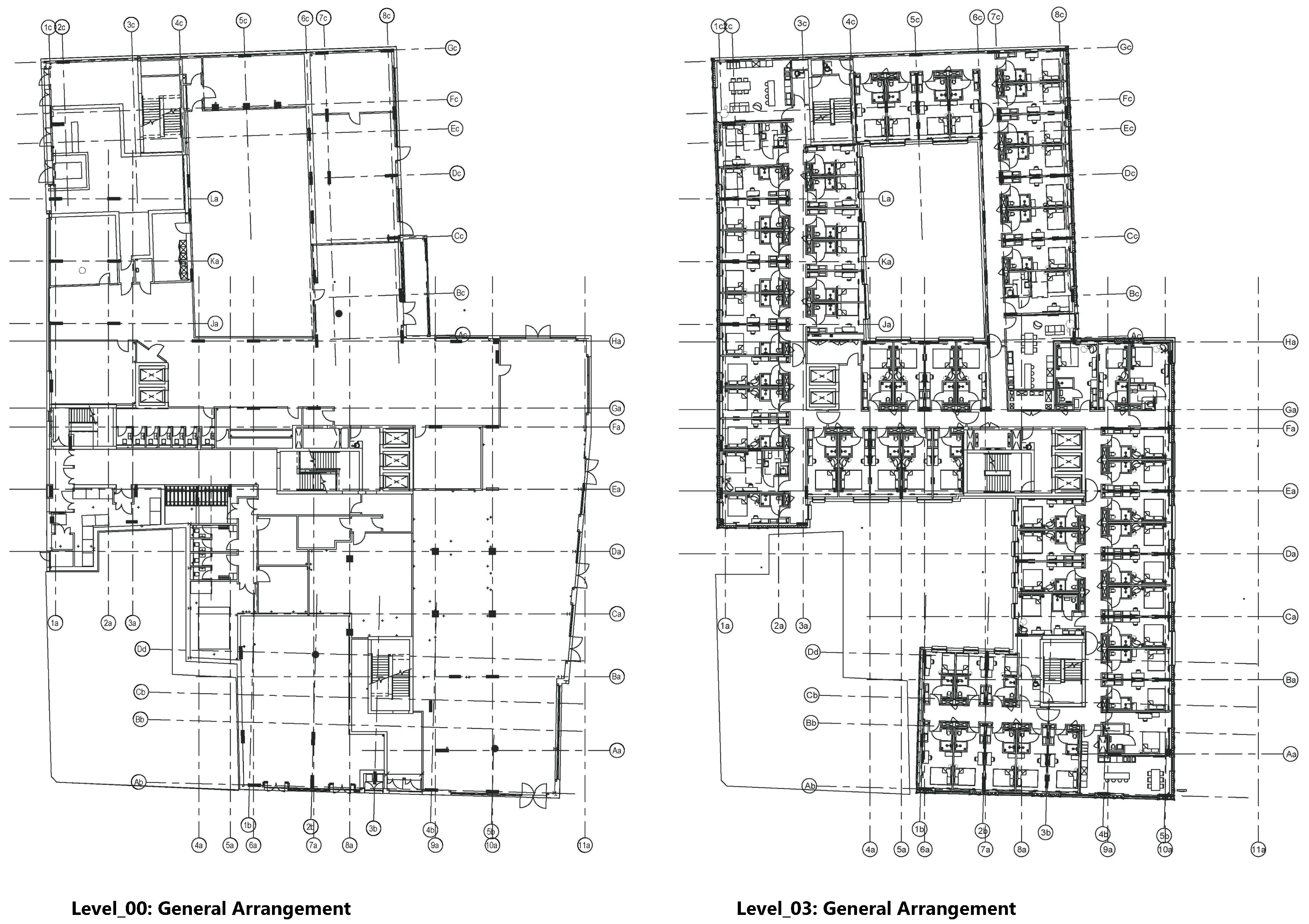
The foundation of any BIM project that utilises PCD is the acquisition of precise and comprehensive data. This involves the deployment of 3D laser scanning technology, which emits laser beams to capture millions of points in three-dimensional space. The resulting data, consisting of spatial coordinates, colour, and intensity information, creates a highly accurate digital twin of the real-world environment. The case study used in this research project is a commercial building with 11 levels. The research initially focused on the concrete structure construction phase. The project was initially identified as a non-BIM-based project, and the only available data for this study were 2D drawings, including PDF drawings and paper-based documents. Two sample PDF drawings for the Ground Level and Level 3 are depicted in Figure 2. A Trimble X7 laser scanner was used in this project to collect data from the existing concrete structure during the construction phase. The scanner has two scan modes, including standard and high sensitivity. The standard mode was used to collect the data for this project. Some of the X7 specs are illustrated in Table 1. More information about the scanner can be found on the Trimble X7 3D Laser Scanner—Datasheet web page (https://fieldtech.trimble.com/resources/product-guides-brochures-datasheets/datasheet-trimble-x7-3d-laser-scanner, accessed on 28 May 2024).
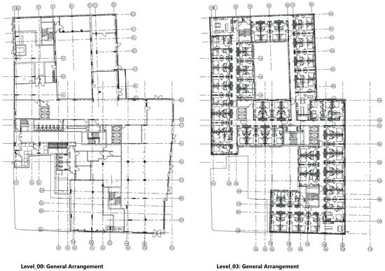
Figure 2.
Level 00 and Level 03 sample PDF drawings.

Table 1.
Some of the Trimble X7 specifications.
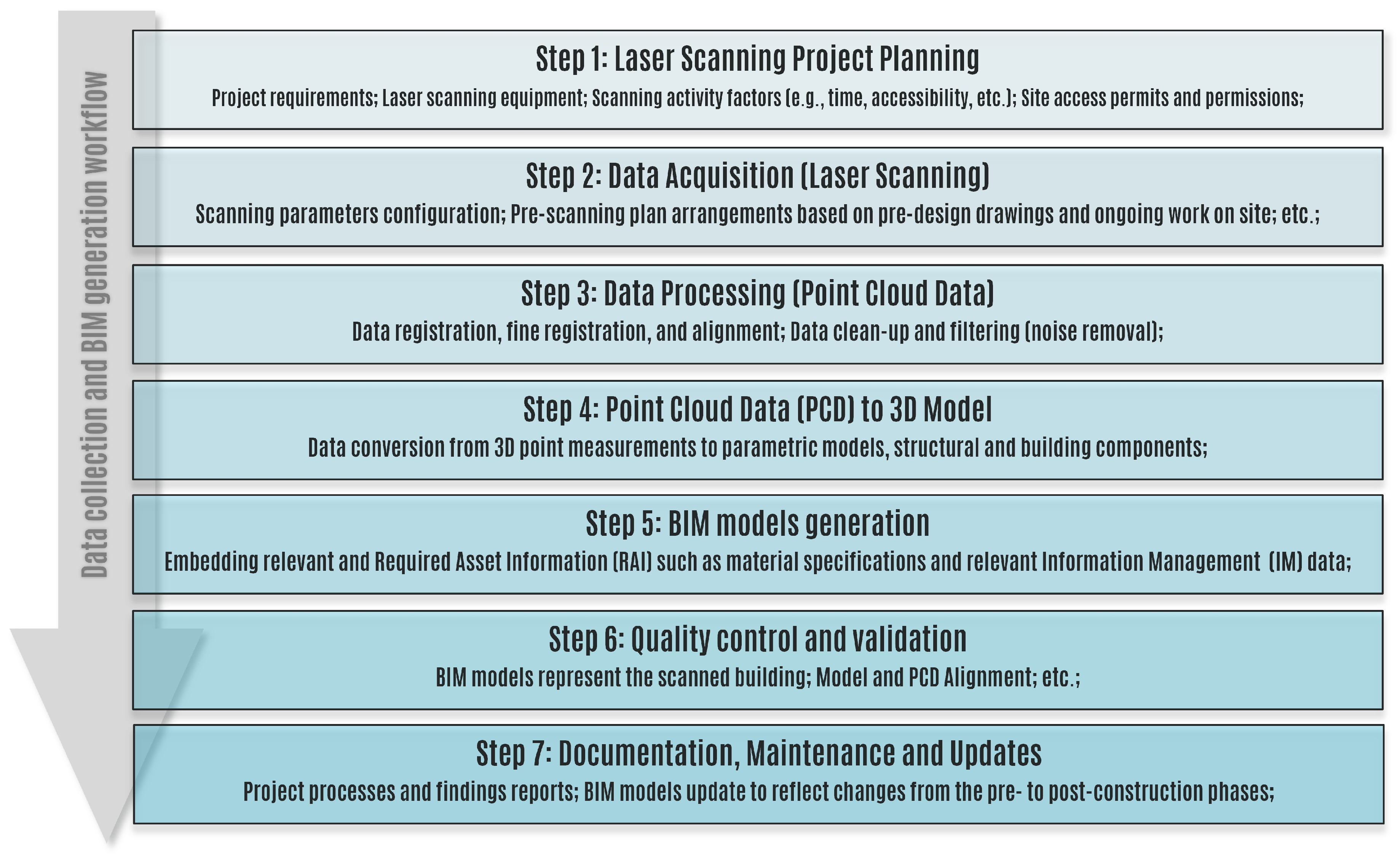
The development of a BIM model utilising PCD entails several procedural steps. Figure 3 provides an overview of the project workflow. Additionally, the Scan-to-BIM process encompasses various supplementary procedures, such as converting PCD to mesh for identifying surfaces and creating 3D models. However, it is important to note that these supplementary steps fall beyond the current scope of this research at this stage of the project and are not included in the procedural steps. The steps depicted in Figure 3 will be described and analysed in more detail in the following sections, focusing on the data acquisition and spatial modelling processes.

Figure 3.
Workflow of generating BIM models utilising PCD.
4.1. Data Acquisition
In this research, the commencement of the data acquisition process coincided with the initiation of the second-level structural assembly, i.e., Levels 0 and 1 structure were completed before data collection commenced. The reason was that concrete formworks were required to be removed from the floors in order to commence the scanning process. In order to expedite the data acquisition process, the existing architectural and structural floor plan drawings were used to arrange the scanning locations manually. The existing planning drawings served as the basis for determining the number of scan stations and the total scan duration for the designated floor. The standard scanning duration for the X7 scanner, amounting to 2.35 min per scan in 360°, was employed in the time calculation. It is important to emphasise that these calculations were predicted based on the presumption that the floors were devoid of any obstructions or on-site construction equipment.
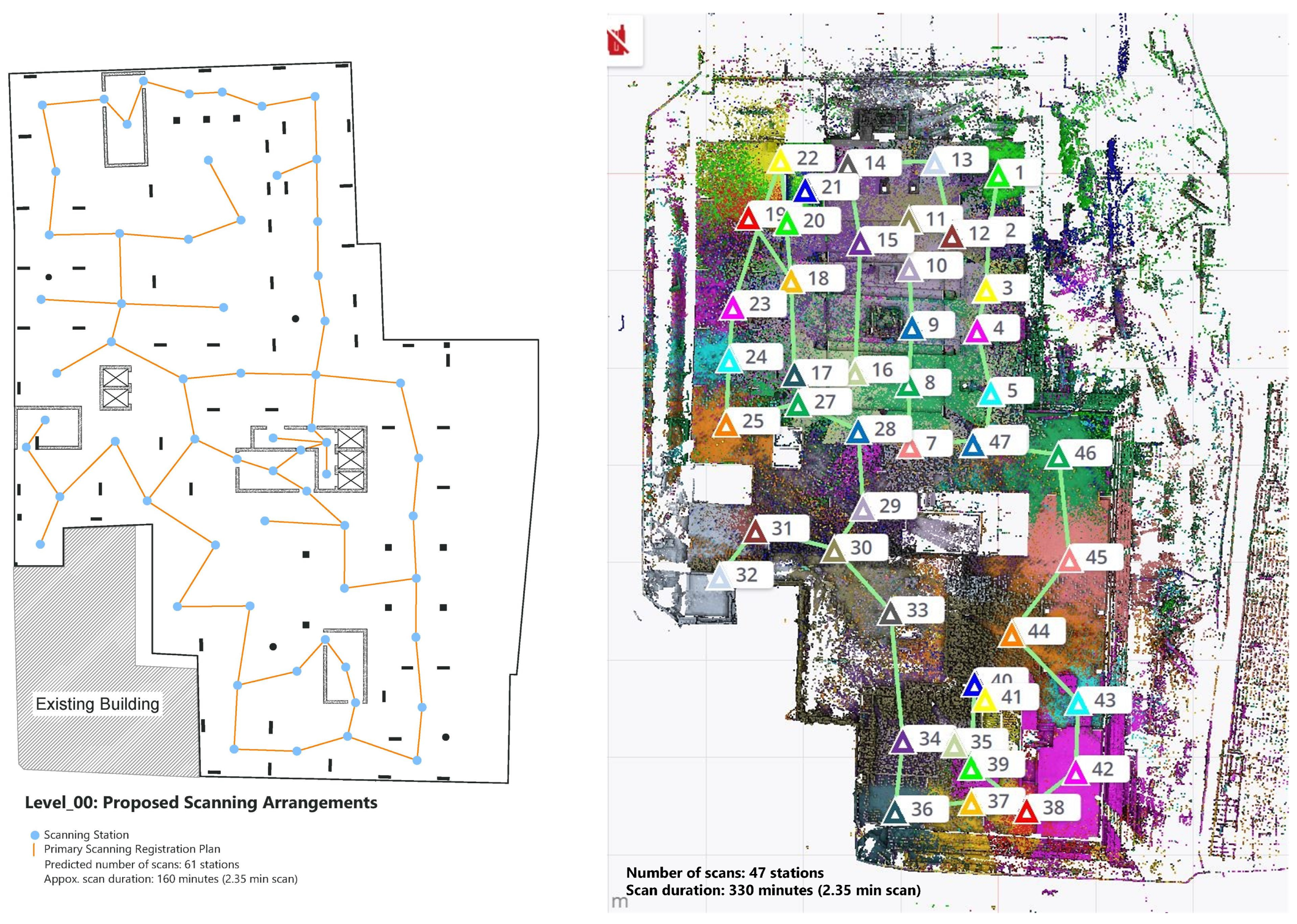
The number of scan stations and the overall scan duration experienced significant alterations upon the initiation of the scanning process at the construction site due to the allocation of floor space for storage purposes and the presence of contractors and sub-contractors working on-site. For example, the pre-arranged projections indicated that 61 scan stations and an estimated total time of 160 min were required to complete the data capture on Level 0 (Ground Level). However, in practice, the duration of the scanning process for Level 0 was 330 min, and the number of scan stations was 47. The increase in scanning duration was primarily attributable to the ongoing construction activities and the corresponding obstructions, including the storage of construction materials and equipment on the ground floor. Conversely, the originally predicted 61 scan stations were reduced to 47 stations. Figure 4 depicts both the pre-arranged drawing and the actual scanning plan implemented for Level 0.
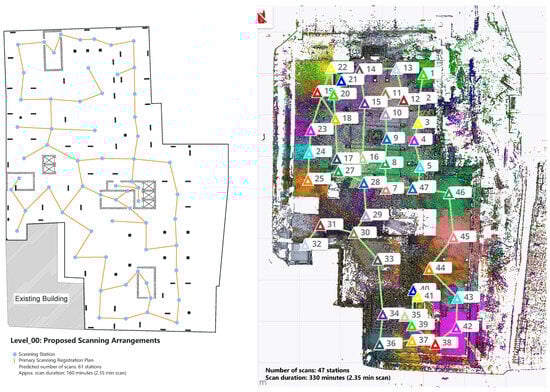
Figure 4.
Left: Pre-arranged scanning plan for the ground level; Right: PCD captured on-site—scanning plan (Screenshot from X7 Trimble Table).
The same procedural methodology was applied to the collection of data for the remaining floors. By the time the scanning team reached Level 2, the delivery and subsequent storage of prefabricated bathrooms on the respective floors commenced. This presented an additional obstruction that contributed to delays in the data acquisition process. As a result of the presence of construction materials, equipment, and prefabricated components, there was a notable increase in both the number of scan stations required and the duration of scanning activities. The increase in the number of scans and scanning duration had consequential impacts on the data quality, such as slight deviations. Although the number of scans was increased in order to capture more comprehensive and accurate data, the equipment on the construction site obstructed the field of the laser scanner view, resulting in the diminished overlap between the scan stations. This issue had a considerable impact on the registration process, resulting in the incorporation of additional scan stations in order to increase the overlap between the adjacent stations.
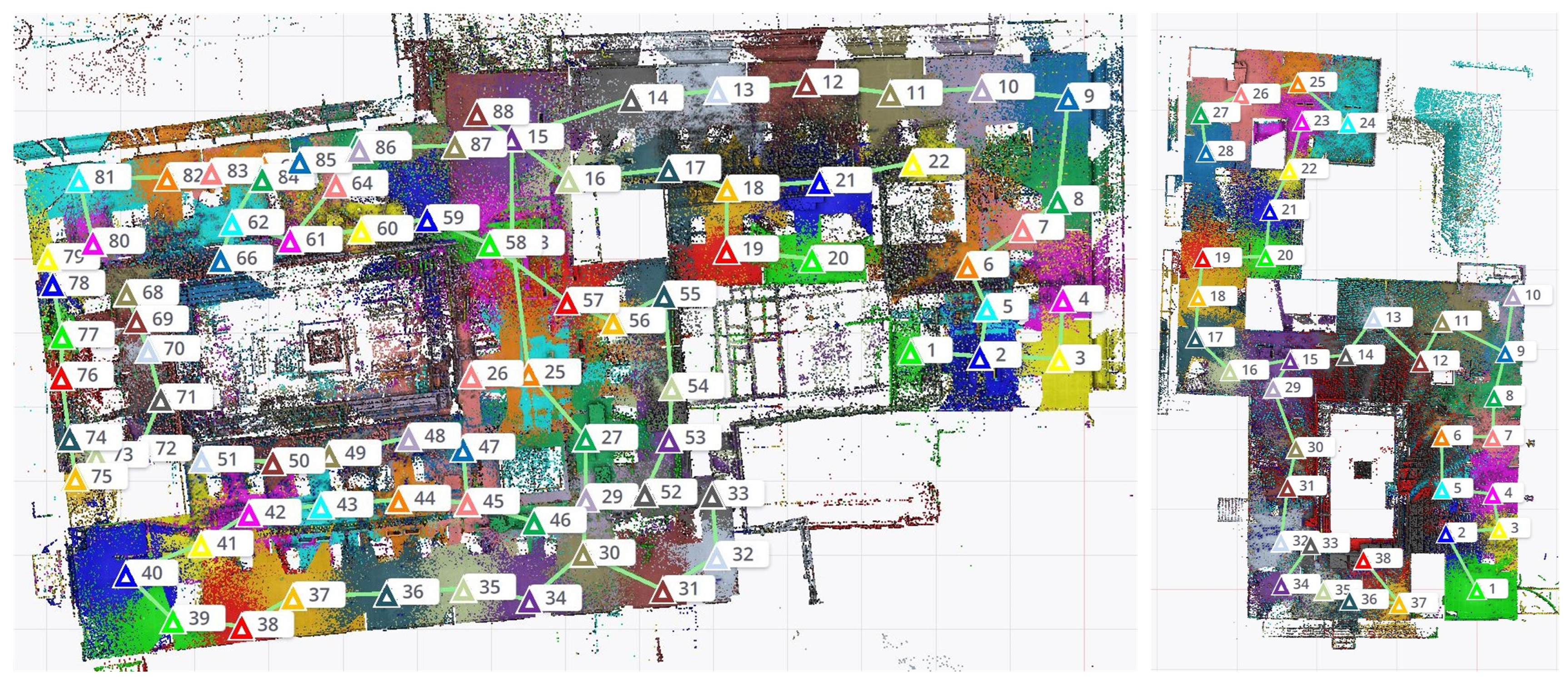
Consequently, it was required to revisit the previously completed levels and collect supplementary data corresponding to the adjacent locations with minimum overlap thresholds. The additional scan points proved and expedited the registration and fine registration processes. Figure 5 provides a visual representation of the on-site scanning plan for Level 2, encompassing 88 scans with the presence of obstructions on the floor (construction materials, equipment, and prefabricated components) and Level 6, encompassing 38 scans without the presence of obstructions. Moreover, having access to the material and equipment delivery schedules could be a proactive strategy that can lead to a smoother scanning process, potentially resulting in improving data accuracy, reducing data acquisition time and scanning stations, increasing safety measures, and allowing proper coordination.

Figure 5.
Left: Level 2 scanning plan completed with 88 scans; Right: Level 6 scanning plan without occlusions on the floor.
Point cloud registration is a critical process in the field of surveying and geospatial data processing. It involves aligning and merging multiple point cloud datasets to create a unified and accurate 3D representation of a surveyed area or object. As mentioned previously, the Trimble X7 was employed to acquire the PCD. One of the advantages of using the Trimble X7 scanner along with the Trimble Perspective software is that the data captured by the device is processed automatically based on the default overlap and coverage settings between previously scanned locations and the new entry. The Trimble Perspective features were initially used to pre-process the data when capturing PCD. Although the PCD can be further processed at a certain level and exported directly in different formats using the Trimble Perspective software, the TBC software was employed in this research to process the captured data further, such as data alignment, fine registration, and PCD quality monitoring.
Trimble Business Centre (TBC) is a well-known software used in the surveying and construction industry that offers powerful tools for point cloud processing, such as registration and fine registration. In a normal scanning environment, the PCD needs to be imported into the point cloud software in order to register and fine-register the laser scanning output data. This process is normally carried out manually and can be considered time-consuming. In the case of low data overlap between certain scan stations, TBC provides tools for initial alignment, which involves a rough alignment of PCDs based on common features or control points. This step helps bring the datasets closer to each other in terms of their spatial orientation and increases the coverage between scan stations, resulting in more accurate data. Additionally, the Autodesk ReCap software (v2024) was also utilised in parallel to the TBC to register and fine-register points. The manual registration features of ReCap were used to complete the registration process.
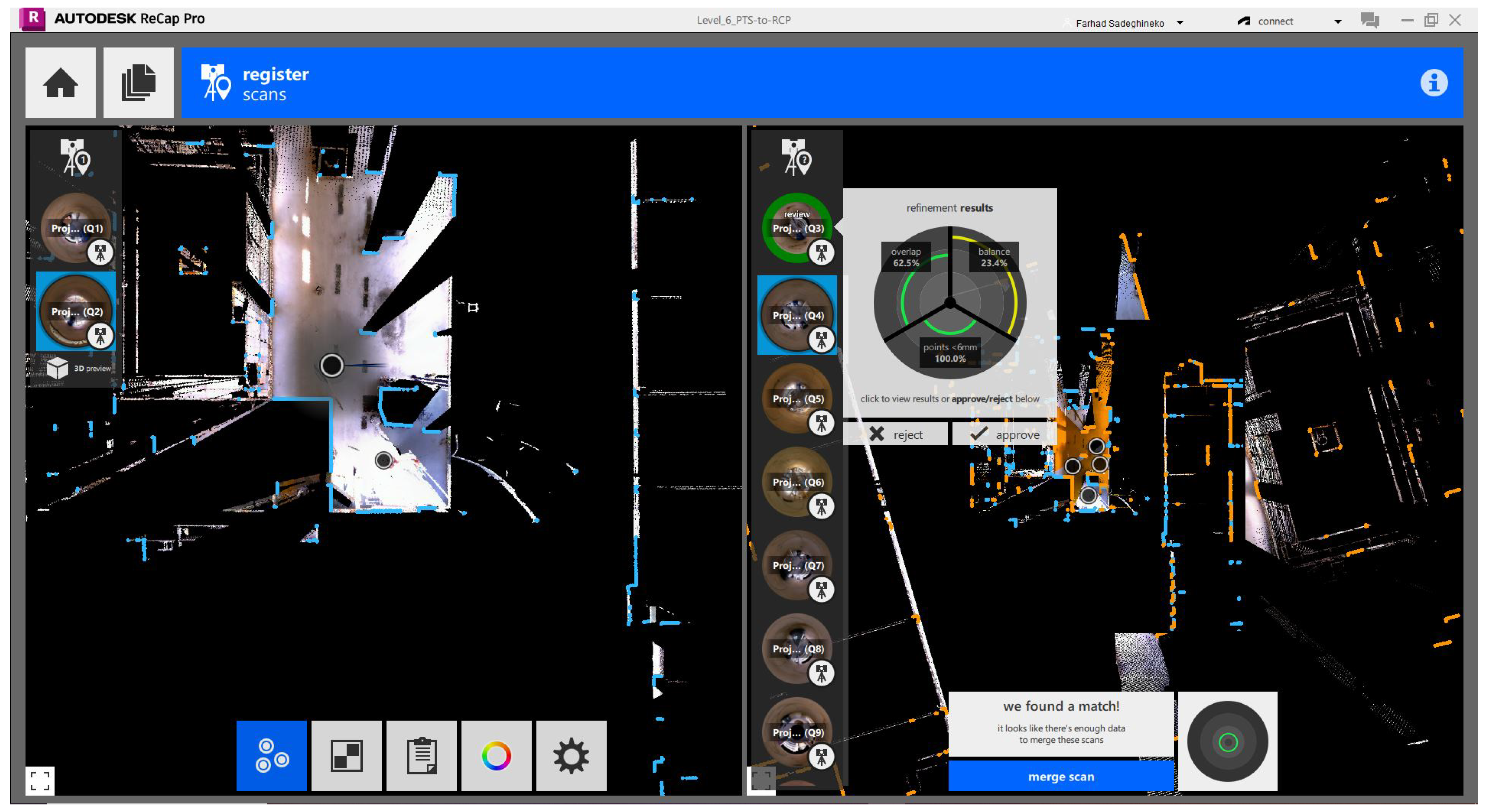
After the initial alignment, the fine registration process begins, where the software refines the alignment to achieve a highly accurate match between the datasets by utilising the Iterative Closest Point (ICP) algorithm [24,51], which is a common technique in the fine registration process. Fine registration is crucial for creating a seamless and precise 3D point cloud model. The feature-based matching and control point features of the software were used where further processing was required in order to improve registration accuracy. The feature-based matching uses the distinct and recognisable features in the data, and the control points act as tie points between datasets and help in fine-tuning and alignment. Figure 6 depicts the registration and fine registration of Level 6 PCD in the Autodesk ReCap software.
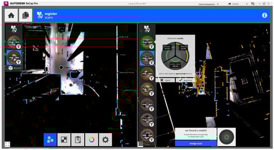
Figure 6.
The registration and fine-registration of Level 6 PCD in Autodesk ReCap.
In summary, the initial pre-arranged scanning plans, based on idealised scenarios devoid of obstructions or on-site equipment, were considerably misaligned with the practical implementation on the construction site. This resulted in substantial differences in both the number of scan stations and the overall scanning duration. Notably, the presence of on-site obstructions necessitated a reassessment of the scanning strategy, causing delays and inaccuracy in data. This emphasises the importance of flexibility and adaptability in data collection strategies in dynamic construction environments. It is crucial to acknowledge that the real-world conditions in construction sites are subject to frequent changes, necessitating continuous adjustments to scanning plans and procedures [52]. The practical outcome of the scanning processes mentioned above can be an example of how unforeseen factors, such as construction activities and on-site storage, can significantly impact the scanning process, resulting in both time and resource inefficiencies.
4.2. Spatial Modelling Using Integrated Advanced Technologies
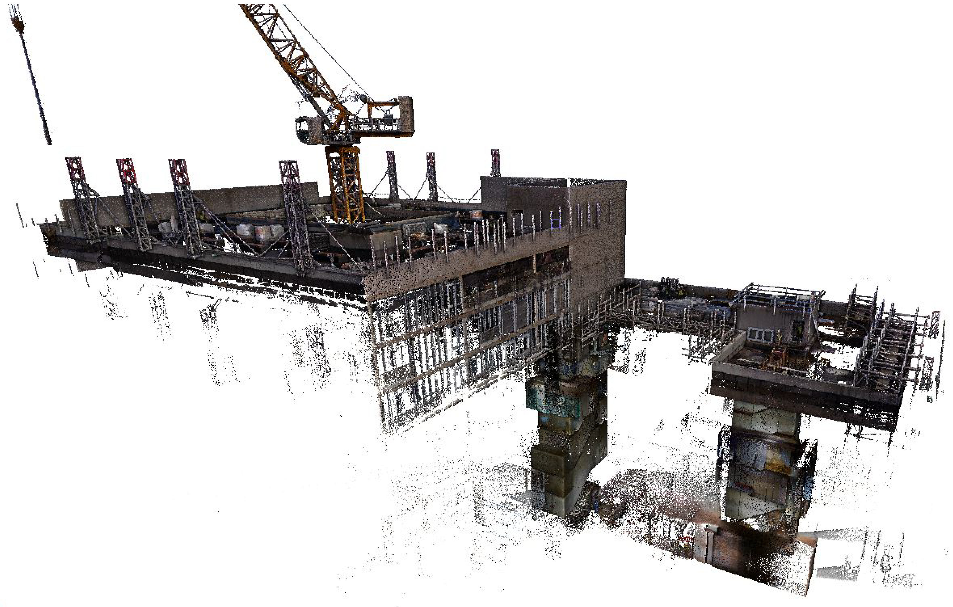
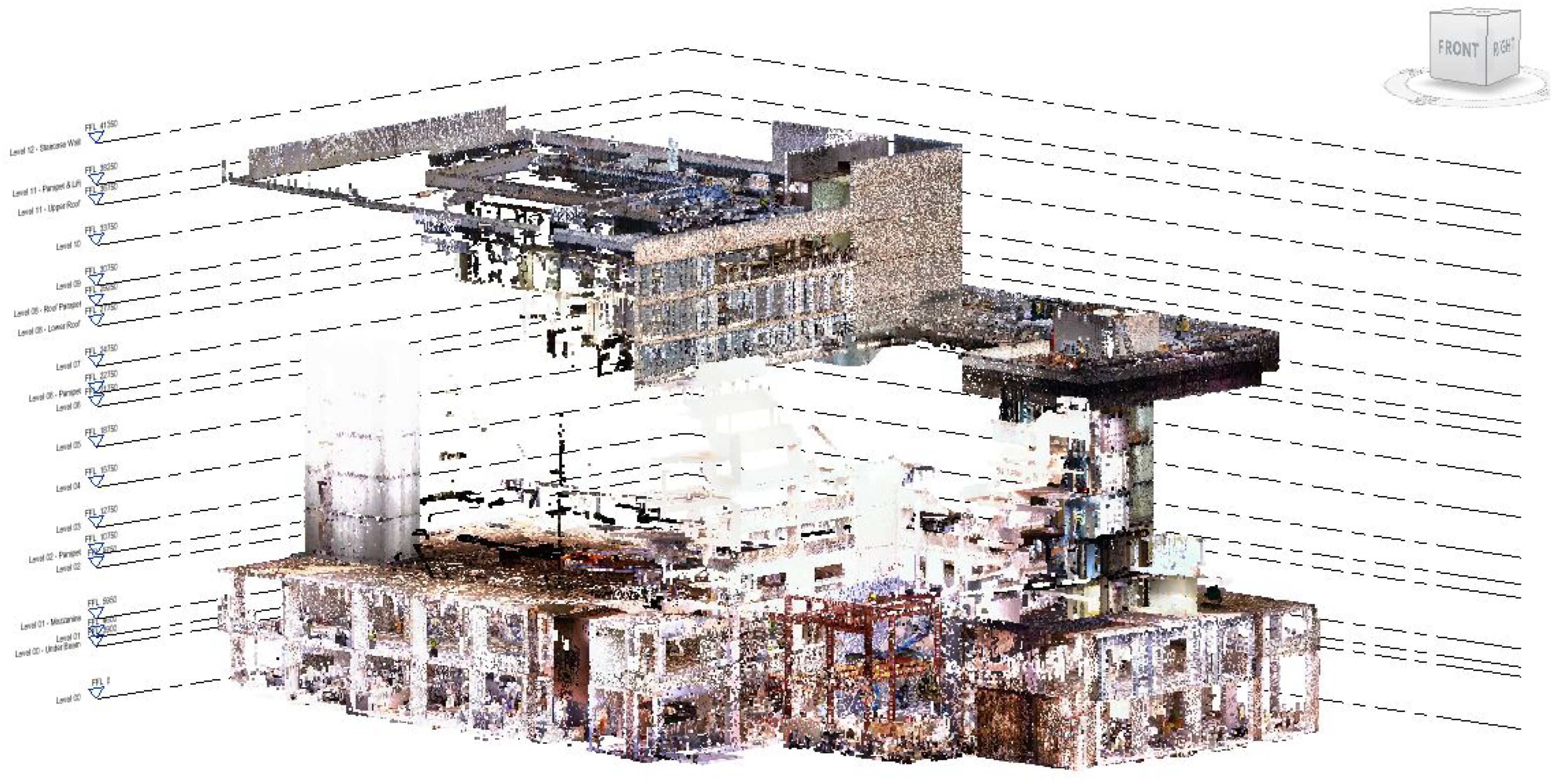
Once the point cloud data has been accurately captured and processed in previous steps, the next critical step is to import the PCD into a BIM-driven application that supports laser scanning output data. The Trimble Business Centre (TBC) and Autodesk ReCap software were utilised to pre-process the captured data initially. Autodesk Revit 2024, as widely used BIM-driven platform, was employed in this research to process the data further in terms of the realignment of point clouds and to generate the parametric models. This integration can be considered as the cornerstone upon which the BIM model will be constructed. Autodesk Revit supports *.rcp and *.rcs point cloud file formats (i.e., Autodesk ReCap software file extensions that are supported by the Autodesk Revit software). It is vital to ensure that the PCD is exported in a compatible format for seamless integration. Figure 7 illustrates integrated and realigned point cloud datasets for several levels in Autodesk Revit.
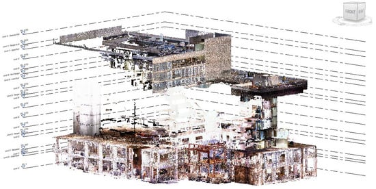
Figure 7.
Imported point cloud data in Autodesk Revit, including levels 0 and 1, vertical circulation (stairs), and roofs.
One of the initial challenges in using point cloud in BIM-enabled applications to create as-built models can be the size of data linked to the BIM project. Depending on the size of the construction project, the size of the collected point cloud varies and directly impacts the data final processing and alignment procedures within the application. Another key factor in processing point clouds in such applications is the computer specs. It is worth noting the computer specs used for this project to highlight its importance in incorporating point cloud data with BIM projects. Table 2 illustrates some of the relevant specs for the computer used for this project.
Table 2.
Some of the computer specs utilised for implementing this project.
The size of the point cloud relies on various factors, such as the point density, the duration and frequency of the data acquisition, and number of scans required when capturing data [24,53]. The size of the point clouds captured from the focus project significantly increased due to the size and progress of the construction project, the site occlusions, and an increase in scan numbers, which directly impacted the data acquisition, pre-processing, integration, and alignment strategies in this project. For example, the size of point cloud datasets illustrated in Figure 7 are as follows: Level 0—65.5 GB (47 scan stations); Level 1—50.9 GB (39 scan stations); Level 3—229 GB (238 scan stations); and the vertical circulation data—87.3 GB (152 scan stations), resulting in a total size of 432.7 GB of external data linked to the Revit project. Hence, the collected data was divided into level-specific portions and were linked to the BIM project individually to address some of these challenges. Furthermore, the filtering features of the application were also utilised to manage the data linked to the Revit project and to facilitate the point cloud integration and alignment processes to create a cohesive 3D representation of captured data. Although these solutions facilitated the data management in the application, they increased the processing effort, which can be considered one of the well-known laser scanning characteristics [37,54].
Generating BIM models from point cloud data, also known as Scan-to-BIM, can be considered an iterative and detail-oriented process [25]. The main goal is to accurately recreate the physical environment, ensuring that all elements and components are represented as constructed to capture the as-is conditions. Revit structural template was used as a foundational base for this project, ensuring that the various components were systematically organised and integrated. Linked point clouds were meticulously aligned to form a cohesive dataset. However, this alignment process is not without its challenges. For example, minor deviations in the point clouds can arise due to the complexities encountered during the scanning process. These complexities may include the presence of construction materials, equipment, and prefabricated components within the scanned environment, which can adversely affect registration factors such as overlap, point density, and balance factors, as illustrated in Figure 6. Another factor could be the sudden movement of construction equipment within the scanned environments, reducing the overlap ratios between scan stations. As a result, scan stations were required to be re-registered through a manual point-to-point selection and registration procedure, which can be considered a time-consuming process, particularly in large construction projects.
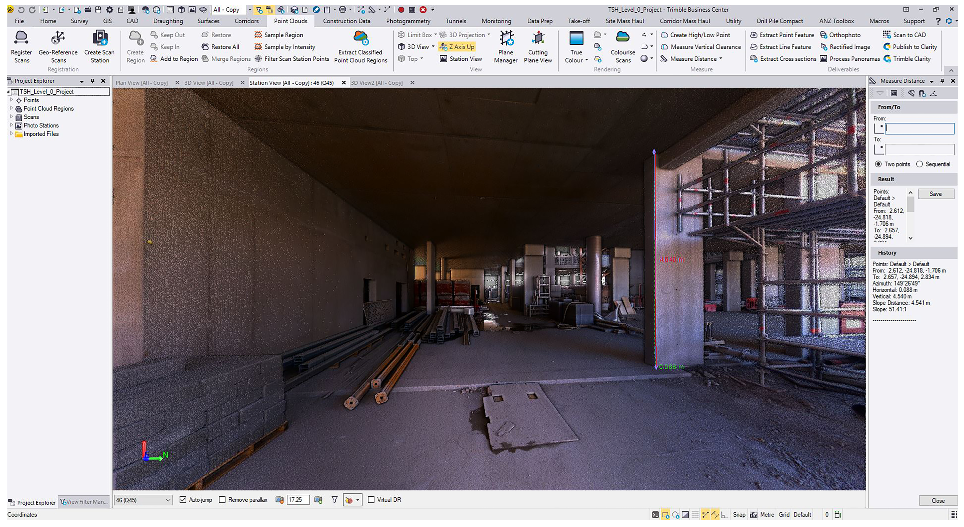
These deviations present significant obstacles in aligning the point clouds and establishing the project levels accurately. The 2D drawings and supplementary project information were also employed to make informed decisions to mitigate the issues mentioned above. Additionally, the scanner image database is also utilised to discern connection points between point cloud datasets and the components created therein (Figure 8). To further support the project set-up, on-site manual measurement surveys were conducted, providing essential data for the accurate placement of point clouds and the determination of accurate level heights and model insertions. Point cloud data were initially used to position structural components within the project, ensuring that the digital model accurately reflects the physical structure. However, further adjustments, such as column rotations and wall connections, were applied to components in order to rectify issues that occurred during the point cloud registration, integration, and alignment, like data deviations. The structural model generated for this project is illustrated in Figure 9. In spite of that, the process of integrating 3D models from laser scanning and document-based techniques into BIM for live building projects is notably challenging and time-intensive, involving complex elements and a significant amount of high-resolution data. Research in the BIM field is actively exploring automatic solutions to these challenges, aiming to significantly reduce costs and streamline the time-consuming nature of these surveys [55,56]. However, the development of an effective automated methodology to facilitate these processes remains an ongoing challenge, with manual methods continuing to remain the current and standard practice within the industry.

Figure 8.
The use of scan images in addition to the point cloud data for further assessments in the TBC software.
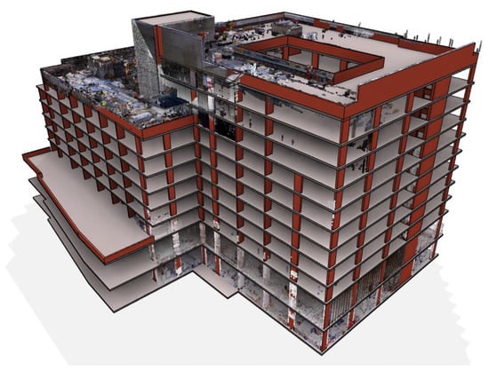
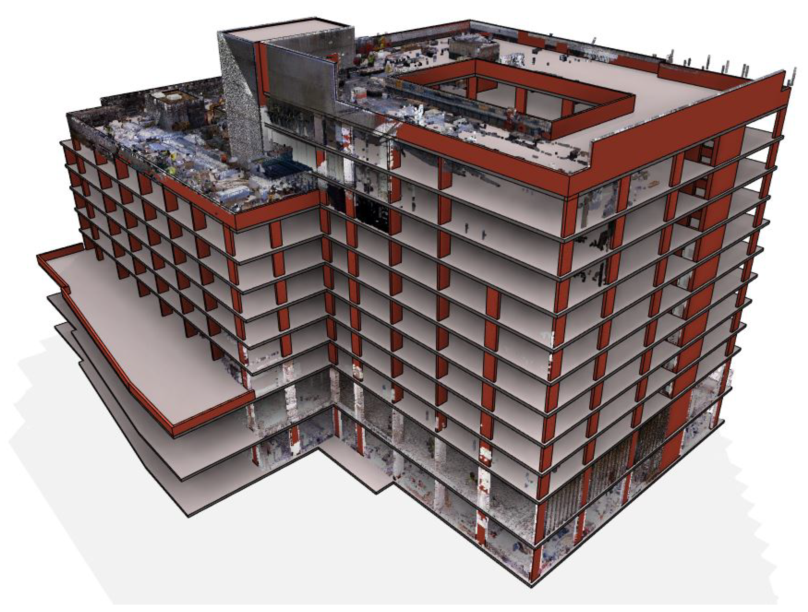
Figure 9.
Structural model generated using point cloud and structural elements in Autodesk Revit 2024.
In addition to the geometric modelling features, BIM platforms are also designed to facilitate the documentation processes for embedding semantic information in building components for existing and new structures. With regard to existing structures, both geometric data and semantic information are required in order to generate models, whereas new constructions, including live building projects, benefit from embedded information through object libraries within the application. Modifications may be necessary for adapting BIM to generated elements. In this project, the existing structural data, such as construction details, datasheets, and reports, were additionally consulted to collect further information used in developing Revit families for various structural components, including different types of columns, structural walls, floor slabs, and roofs. This information will later be employed to enhance the documentation process.
It is necessary to mention that the research presented in this paper mainly focuses on the integration of laser scanning data and BIM, and the documentation and maintenance phases will be the next steps of this project. However, it is important to refine and add sufficient details to the components to generate comprehensive and informative building models based on Level of Detail (LoD) requirements in order to implement a successful BIM documentation process. Therefore, it is worth mentioning that the British Standards Institute (BSI) introduced the BS EN ISO 19650 series, focusing on Information Management (IM) using BIM. The series delineates different aspects of BIM processes, encompassing the foundational concepts and principles, management of information during the asset delivery and operational phases, facilitation of information exchange and interoperability, and the security-minded approach to IM from the pre-design stage of a building project onwards. For the purposes of this project, these documents and guidelines will be employed during the documentation phase, in collaboration with the project team, to achieve an appropriate LoD as necessitated by the stakeholders. This strategic approach will assist in facilitating the transition of a non-BIM-enabled project into a BIM-enabled endeavour.
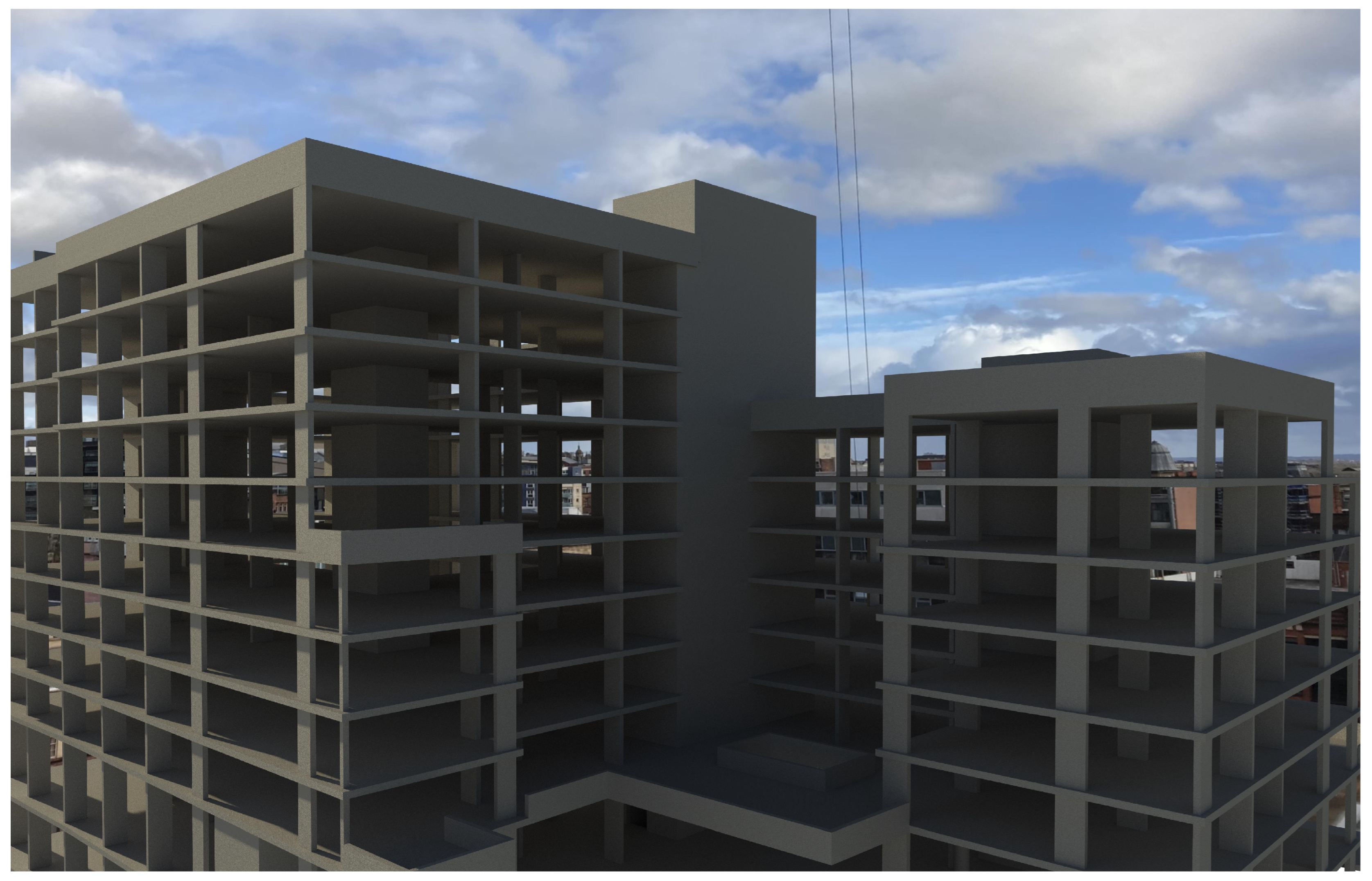
BIM’s transformative features improve the representation of data throughout the lifecycle of a building project [57]. These features of BIM can be utilised to enhance decision making, collaboration, and project outcomes [2,56]. It can also facilitate the intuitive understanding of construction processes by providing a 3D visual context from which stakeholders can easily grasp the spatial relationships between building components, their corresponding dimensions, the scale of building elements, safety measures, and applications of sustainability [1]. Figure 10 depicts a visualised version of the structural model generated in Autodesk Revit.

Figure 10.
A visualised version of the structural model generated in Autodesk Revit 2024.
BIM documentation is essential for understanding the exact conditions of building projects, which is also critical for effective maintenance planning. The BIM processes and laser scanning technology offer a comprehensive and detailed representation of building projects, which is invaluable for various aspects of maintenance and operating procedures, such as structural integrity, facilities management, and safety measures [27,43]. The converted point cloud data into BIM models can offer precise as-built documentation. The point cloud data, BIM models, and documentation can facilitate more efficient construction and project management by providing a holistic view of a building’s entire lifecycle [28,43]. This integration, enabled by the digital nature of BIM processes, can also assist with reducing the risk of errors and misunderstandings among stakeholders, leading to more effective management, maintenance, and operation [2]. Last but not least, laser scanning and BIM integration can also contribute to reduced material waste and more sustainable building practices [18,47,58].
5. Discussion
Incorporating laser scanning and BIM into live construction projects that are not BIM-driven presents challenges in terms of data and model accuracy, as-built documentation, cost, time, and project quality and performance. This section synthesises the findings from the case study and literature to highlight the key aspects of incorporating laser scanning and BIM. Overall, the case study emphasised the practicalities of integrating advanced technologies that could potentially provide a viable systematic approach for facilitating the success of a construction project where there is an absence of a BIM model.
It is well-established that laser scanning technology captures spatial data with high precision, enhancing the data accuracy and forming the basis for creating 3D models that can be enriched with semantic information and potentially reflect the as-built environment [2,27]. Laser scanning offers a substantial reduction in the time required for data acquisition compared to conventional manual procedures, leading to potential cost reductions and construction operation improvements [16,43]. With regard to live construction projects, although site obstructions can affect the quality and perhaps the accuracy of data collected by laser scanners, the method remains efficient. The data precision significantly reduces the likelihood of errors and inconsistencies during the modelling process, enhancing the overall project outcomes [49]. However, in large-scale construction projects, like the case study in this paper, data processing and management can be considered as one of the major challenges when integrating laser scanning data with BIM. The technological and procedural complexities of such integration require specialised knowledge and skills in order to implement the process and create an accurate model that mirrors the actual physical structure.
The size of the scan data and the computer specifications utilised for such projects can also be considered an important barrier in the integration process. While the computer specifications for executing this project are deemed adequate for data processing and 3D modelling, the size and amount of linked data in the Revit project notably increased the processing effort and workload, which can also be referred to as a time-consuming procedure. However, regardless of these barriers, the use of laser scanning technology, in contrast to traditional survey methods, enhanced the process of generating models for the as-is condition of the case study project [24,28]. Moreover, the developed as-built BIM models can be further utilised, and more details can be included in them at later stages of the project if necessary, making working on the project incremental [9].
With regard to information management, the increase of information embedded in models can initially facilitate some of the management processes, such as project management, construction safety, quality control, and asset management. However, models overloaded with information may also result in issues in terms of information management, such as data processing, storage, reuse, and updates. Hence, it is important to adopt the collaboration features of BIM to identify the required LoD. An appropriate LoD will subsequently increase the efficiency of the BIM documentation process [9,31]. In the construction sector, there is an increasing emphasis on the comprehensive digitised documentation of construction processes. This detailed documentation, e.g., digital representation of the physical and functional characteristics of a building, can significantly improve and facilitate subsequent project maintenance and operations [22,56].
Well-designed and structured BIM documentation can potentially centralise all information about a building project in one place, making it accessible to permitted stakeholders. It allows for improved efficiency and faster project delivery by avoiding mistakes, discrepancies, and duplicate work, perhaps leading to significant cost savings at both the delivery and operational stages of a building’s lifecycle. The next steps of this continuous project will be twofold. First, it will continue focusing on employing the BS EN ISO 19650 standards to establish the necessary BIM documentation processes, aiming to pinpoint the obstacles and constraints associated with converting an ongoing construction project which does not utilise BIM into one that is BIM-enabled. Second, the project will also focus on identifying both automated and semi-automated approaches that can be integrated with the existing manual practices to improve the effectiveness of laser scanning and BIM integration, such as an automated method to facilitate the scanning process in terms of data collection time and accuracy.
6. Conclusion
This paper has provided an in-depth examination of the practicalities of incorporating 3D laser scanning with BIM in live construction projects. Incorporating laser scanning and BIM into live construction projects that are not BIM-driven can present challenges in terms of data and model accuracy, as-built documentation, cost, time, and project quality and performance. The limitations identified in this approach include data processing and management, as well as the need for specialised equipment and skills for the effective implementation of such integrations. However, the transformative power of BIM in its ability to enhance visualisation throughout the lifecycle of a building project, leveraged to considerably improve the possibilities for decision making, collaboration, and project outcomes, makes this worthwhile.
Author Contributions
Conceptualization, F.S., K.L. and M.T.; Methodology, F.S., K.L. and M.T.; Software, F.S.; Validation, F.S. and K.L.; Investigation, F.S. and M.T.; Resources, F.S. and M.T.; Writing—original draft preparation, F.S.; Writing—review and editing, F.S., K.L. and M.T.; Visualization, F.S.; Supervision, M.T. All authors have read and agreed to the published version of the manuscript.
Funding
This research received no external funding.
Data Availability Statement
The data collected from the case study project are utilised anonymously in this paper due to permission terms between the authors’ institution and the project team. Hence, there are limitations in making the raw data available. However, the generated BIM model will be available from the authors upon request, excluding the raw data.
Conflicts of Interest
The authors declare no conflicts of interest.
References
- Chatzimichailidou, M.; Ma, Y. Using BIM in the safety risk management of modular construction. Saf. Sci. 2022, 154, 105852. [Google Scholar] [CrossRef]
- Wang, J.; Zhang, S.; Fenn, P.; Luo, X.; Liu, Y.; Zhao, L. Adopting BIM to Facilitate Dispute Management in the Construction Industry: A Conceptual Framework Development. J. Constr. Eng. Manag. 2023, 149, 03122010. [Google Scholar] [CrossRef]
- Ghansah, F.A.; Lu, W. Responses to the COVID-19 pandemic in the construction industry: A literature review of academic research. Constr. Manag. Econ. 2023, 41, 781–803. [Google Scholar] [CrossRef]
- Goedert, J.D.; Meadati, P. Integrating Construction Process Documentation into Building Information Modeling. J. Constr. Eng. Manag. 2008, 134, 509–516. [Google Scholar] [CrossRef]
- Eadie, R.; Browne, M.; Odeyinka, H.; McKeown, C.; McNiff, S. BIM implementation throughout the UK construction project lifecycle: An analysis. Autom. Constr. 2013, 36, 145–151. [Google Scholar] [CrossRef]
- Cheng, T.; Teizer, J. Real-time resource location data collection and visualization technology for construction safety and activity monitoring applications. Autom. Constr. 2013, 34, 3–15. [Google Scholar] [CrossRef]
- Chan, D.W.M.; Olawumi, T.O.; Ho, A.M.L. Perceived benefits of and barriers to Building Information Modelling (BIM) implementation in construction: The case of Hong Kong. J. Build. Eng. 2019, 25, 100764. [Google Scholar] [CrossRef]
- Sadeghineko, F.; Kumar, B. Facilitating Information Exchange for 3D Retrofit Models of Existing Assets Using Semantic Web Technologies. In Enabling the Development and Implementation of Digital Twins, Proceedings of the 20th International Conference on Construction Application of Virtual Reality, Online, 30 September 2020–2 October 2020; Dawood, N., Rahimian, F.P., Seyedzadeh, S., Sheikhkhoshkar, M., Eds.; Teesside University Press: Middlesbrough, UK, 2020; pp. 358–371. [Google Scholar]
- Amin, K.F.; Abanda, F.H. Building Information Modelling Plan of Work for Managing Construction Projects in Egypt. J. Constr. Dev. Ctries. 2019, 24, 23–61. [Google Scholar] [CrossRef]
- Mahdjoubi, L.; Moobela, C.; Laing, R. Providing real-estate services through the integration of 3D laser scanning and building information modelling. Comput. Ind. 2013, 64, 1272–1281. [Google Scholar] [CrossRef]
- Kavaliauskas, P.; Fernandez, J.B.; McGuinness, K.; Jurelionis, A. Automation of Construction Progress Monitoring by Integrating 3D Point Cloud Data with an IFC-Based BIM Model. Buildings 2022, 12, 1754. [Google Scholar] [CrossRef]
- Ayat, M.; Kang, C.W. Effects of the COVID-19 pandemic on the construction sector: A systemized review. Eng. Constr. Archit. Manag. 2021, 30, 734–754. [Google Scholar] [CrossRef]
- Li, Z.; Jin, Y.; Li, W.; Meng, Q.; Hu, X. Impacts of COVID-19 on construction project management: A life cycle perspective. Eng. Constr. Archit. Manag. 2022, 30, 3357–3389. [Google Scholar] [CrossRef]
- Barlish, K.; Sullivan, K. How to measure the benefits of BIM—A case study approach. Autom. Constr. 2012, 24, 149–159. [Google Scholar] [CrossRef]
- Khoshfetrat, R.; Sarvari, H.; Chan, D.W.M.; Rakhshanifar, M. Critical risk factors for implementing building information modelling (BIM): A Delphi-based survey. Int. J. Constr. Manag. 2020, 22, 2375–2384. [Google Scholar] [CrossRef]
- Sacks, R.; Girolami, M.; Brilakis, I. Building Information Modelling, Artificial Intelligence and Construction Tech. Dev. Built Environ. 2020, 4, 100011. [Google Scholar] [CrossRef]
- Leite, F.; Akcamete, A.; Akinci, B.; Atasoy, G.; Kiziltas, S. Analysis of modeling effort and impact of different levels of detail in building information models. Autom. Constr. 2011, 20, 601–609. [Google Scholar] [CrossRef]
- Zhang, L.; Chu, Z.; He, Q.; Zhai, P. Investigating the Constraints to Buidling Information Modeling (BIM) Applications for Sustainable Building Projects: A Case of China. Sustainability 2019, 11, 1896. [Google Scholar] [CrossRef]
- Borkowski, A.S. A Literature Review of BIM Definitions: Narrow and Broad Views. Technologies 2023, 11, 176. [Google Scholar] [CrossRef]
- Almujibah, H. Assessment of Building Information Modeling (BIM) as a Time and Cost-Saving Construction Management Tool: Evidence from Two-Story Villas in Jeddah. Sustainability 2023, 15, 7354. [Google Scholar] [CrossRef]
- Nur Sholeh, M.; Fauziyah, S.; Radian Khasani, R. Effect of Building Information Modeling (BIM) on reduced construction time-costs: A case study. E3S Web Conf. 2020, 202, 02012. [Google Scholar] [CrossRef]
- EL Mounla, K.; Beladjine, D.; Beddiar, K.; Mazari, B. Lean-BIM Approach for Improving the Performance of a Construction Project in the Design Phase. Buildings 2023, 13, 654. [Google Scholar] [CrossRef]
- Westiing, F.A.; Abbas, R.; Skinner, C.; Hanus-Smith, M.; Harris, A.; Kirchner, N. Applications of LiDAR for Productivity Improvement on Construction Projects: Case Studies from Active Sites. In Proceedings of the ISARC. Proceedings of the International Symposium on Automation and Robotics in Construction; IAARC Publications: Oulu, Finland, 2020; Volume 37, pp. 353–361. [Google Scholar]
- Wang, Q.; Qian, P.; Liu, Y.; Li, T.; Yang, L.; Yang, F. Geometric Accuracy Evaluation Method for Subway Stations Based on 3D Laser Scanning. Appl. Sci. 2022, 12, 9535. [Google Scholar] [CrossRef]
- Palčák, M.; Kudela, P.; Fandáková, M.; Kordek, J. Utilization of 3D Digital Technologies in the Documentation of Cultural Heritage: A Case Study of the Kunerad Mansion (Slovakia). Appl. Sci. 2022, 12, 4376. [Google Scholar] [CrossRef]
- Li, H.; Zhang, C.; Song, S.; Demirkesen, S.; Chang, R. Improving Tolerance Control on Modular Construction Project with 3D Laser Scanning and BIM: A Case Study of Removable Floodwall Project. Appl. Sci. 2020, 10, 8680. [Google Scholar] [CrossRef]
- Tan, Y.; Li, S.; Wang, Q. Automated Geometric Quality Inspection of Prefabricated Housing Units Using BIM and LiDAR. Remote Sens. 2020, 12, 2492. [Google Scholar] [CrossRef]
- Lawani, K.; Sadeghineko, F.; Tong, M.; Bayraktar, M. Methodology for retrospectively developing a BIM model from point cloud scans using ongoing building project as case study. J. Eng. Des. Technol. 2024. [Google Scholar] [CrossRef]
- Sadeghineko, F.; Kumar, B. Development of Semantically Rich 3D Retrofit Models. J. Comput. Civ. Eng. 2020, 34, 04020039. [Google Scholar] [CrossRef]
- Sadeghineko, F.; Kumar, B.; Chan, W. A Semantic Web-Based Approach for Generating Parametric Models Using RDF. In Advanced Computing Strategies for Engineering; Springer International Publishing: Berlin/Heidelberg, Germany, 2018; pp. 361–377. [Google Scholar] [CrossRef]
- Sadeghineko, F.; Kumar, B.; Chan, W. Employment of Semantic Web Technologies for Capturing Comprehensive Parametric Building Models. In Advances in Informatics and Computing in Civil and Construction Engineering; Springer International Publishing: Berlin/Heidelberg, Germany, 2018; pp. 111–122. [Google Scholar] [CrossRef]
- Sutherland, I.E. Sketchpad: A man-machine graphical communication system. In Proceedings of the Spring Joint Computer Conference on—AFIPS ’63 (Spring), Detroit, MI, USA, 21–23 May 1963; ACM Press: New York, NY, USA, 1963. [Google Scholar] [CrossRef]
- Eastman, C. The use of computers instead of drawings in building design. AIA J. 1975, 63, 46–50. [Google Scholar]
- Suermann, P.C.; Issa, R.R. The US National Building Information Modeling Standard. In Advances in Civil and Industrial Engineering; IGI Global: Hershey, PA, USA, 2010; pp. 138–154. [Google Scholar] [CrossRef]
- Borkowski, A.S. Evolution of BIM: Epistemology, genesis and division into periods. J. Inf. Technol. Constr. 2023, 28, 646–661. [Google Scholar] [CrossRef]
- Adán, A.; Quintana, B.; Prieto, S.; Bosché, F. An autonomous robotic platform for automatic extraction of detailed semantic models of buildings. Autom. Constr. 2020, 109, 102963. [Google Scholar] [CrossRef]
- Zhang, D.; Liu, T.; Li, S.; Luo, H.; Ding, G.; Su, Z.; Xie, C.; Zhang, S.; Feng, P. Three-dimensional laser scanning for large-scale as-built surveying of 2022 Beijing Winter Olympic Speed Skating Stadium: A case study. J. Build. Eng. 2022, 59, 105075. [Google Scholar] [CrossRef]
- Tang, X.; Wang, M.; Wang, Q.; Guo, J.; Zhang, J. Benefits of Terrestrial Laser Scanning for Construction QA/QC: A Time and Cost Analysis. J. Manag. Eng. 2022, 38, 05022001. [Google Scholar] [CrossRef]
- Sharif, M.M.; Chuo, S.; Haas, C.T. Rapid 3D Quality Control in Prefabrication Using a 3D Digital-Templates Framework. J. Constr. Eng. Manag. 2022, 148, 04022117. [Google Scholar] [CrossRef]
- Liu, J.; Xu, D.; Hyyppa, J.; Liang, Y. A Survey of Applications with Combined BIM and 3D Laser Scanning in the Life Cycle of Buildings. IEEE J. Sel. Top. Appl. Earth Obs. Remote Sens. 2021, 14, 5627–5637. [Google Scholar] [CrossRef]
- Mellado, F.; Wong, P.F.; Amano, K.; Johnson, C.; Lou, E.C.W. Digitisation of existing buildings to support building assessment schemes: Viability of automated sustainability-led design scan-to-BIM process. Archit. Eng. Des. Manag. 2019, 16, 84–99. [Google Scholar] [CrossRef]
- Valero, E.; Bosché, F.; Bueno, M. Laser scanning for BIM. J. Inf. Technol. Constr. 2022, 27, 486–495. [Google Scholar] [CrossRef]
- Ham, N.; Lee, S.H. Empirical Study on Structural Safety Diagnosis of Large-Scale Civil Infrastructure Using Laser Scanning and BIM. Sustainability 2018, 10, 4024. [Google Scholar] [CrossRef]
- Nguyen, T.A.; Do, S.T.; Le-Hoai, L.; Nguyen, V.T.; Pham, T.A. Practical workflow for cultural heritage digitalization and management: A case study in Vietnam. Int. J. Constr. Manag. 2022, 23, 2305–2319. [Google Scholar] [CrossRef]
- Qiu, Q.; Wang, M.; Guo, J.; Liu, Z.; Wang, Q. An adaptive down-sampling method of laser scan data for scan-to-BIM. Autom. Constr. 2022, 135, 104135. [Google Scholar] [CrossRef]
- Aricò, M.; Brutto, M.L. From scan-to-BIM to heritage building information modelling for an ancient Arab-Norman church. Int. Arch. Photogramm. Remote Sens. Spat. Inf. Sci. 2022, XLIII-B2-2022, 761–768. [Google Scholar] [CrossRef]
- Wu, Z.; Chen, C.; Cai, Y.; Lu, C.; Wang, H.; Yu, T. BIM-Based Visualization Research in the Construction Industry: A Network Analysis. Int. J. Environ. Res. Public Health 2019, 16, 3473. [Google Scholar] [CrossRef]
- Becerik-Gerber, B.; Jazizadeh, F.; Li, N.; Calis, G. Application Areas and Data Requirements for BIM-Enabled Facilities Management. J. Constr. Eng. Manag. 2012, 138, 431–442. [Google Scholar] [CrossRef]
- Wang, J.; Yi, T.; Liang, X.; Ueda, T. Application of 3D Laser Scanning Technology Using Laser Radar System to Error Analysis in the Curtain Wall Construction. Remote Sens. 2022, 15, 64. [Google Scholar] [CrossRef]
- Valero, E.; Mohanty, D.D.; Ceklarz, M.; Tao, B.; Bosche, F.; Giannakis, G.I.; Fenz, S.; Katsigarakis, K.; Lilis, G.N.; Rovas, D.; et al. An Integrated Scan-to-BIM Approach for Buildings Energy Performance Evaluation and Retrofitting. In Proceedings of the International Symposium on Automation and Robotics in Construction (IAARC). International Association for Automation and Robotics in Construction (IAARC), Dubai, United Arab Emirates, 2–4 November 2021. ISARC2021. [Google Scholar] [CrossRef]
- He, Y.; Liang, B.; Yang, J.; Li, S.; He, J. An Iterative Closest Points Algorithm for Registration of 3D Laser Scanner Point Clouds with Geometric Features. Sensors 2017, 17, 1862. [Google Scholar] [CrossRef] [PubMed]
- Zhang, S.; Sulankivi, K.; Kiviniemi, M.; Romo, I.; Eastman, C.M.; Teizer, J. BIM-based fall hazard identification and prevention in construction safety planning. Saf. Sci. 2015, 72, 31–45. [Google Scholar] [CrossRef]
- Ding, Z.; Sun, Y.; Xu, S.; Pan, Y.; Peng, Y.; Mao, Z. Recent Advances and Perspectives in Deep Learning Techniques for 3D Point Cloud Data Processing. Robotics 2023, 12, 100. [Google Scholar] [CrossRef]
- Moselhi, O.; Bardareh, H.; Zhu, Z. Automated Data Acquisition in Construction with Remote Sensing Technologies. Appl. Sci. 2020, 10, 2846. [Google Scholar] [CrossRef]
- Maalek, R.; Lichti, D.D.; Ruwanpura, J.Y. Automatic Recognition of Common Structural Elements from Point Clouds for Automated Progress Monitoring and Dimensional Quality Control in Reinforced Concrete Construction. Remote Sens. 2019, 11, 1102. [Google Scholar] [CrossRef]
- Schönfelder, P.; Aziz, A.; Faltin, B.; König, M. Automating the retrospective generation of As-is BIM models using machine learning. Autom. Constr. 2023, 152, 104937. [Google Scholar] [CrossRef]
- Ivson, P.; Moreira, A.; Queiroz, F.; Santos, W.; Celes, W. A Systematic Review of Visualization in Building Information Modeling. IEEE Trans. Vis. Comput. Graph. 2020, 26, 3109–3127. [Google Scholar] [CrossRef]
- Durdyev, S.; Dehdasht, G.; Mohandes, S.R.; Edwards, D.J. Review of the Building Information Modelling (BIM) Implementation in the Context of Building Energy Assessment. Energies 2021, 14, 8487. [Google Scholar] [CrossRef]
Disclaimer/Publisher’s Note: The statements, opinions and data contained in all publications are solely those of the individual author(s) and contributor(s) and not of MDPI and/or the editor(s). MDPI and/or the editor(s) disclaim responsibility for any injury to people or property resulting from any ideas, methods, instructions or products referred to in the content. |
© 2024 by the authors. Licensee MDPI, Basel, Switzerland. This article is an open access article distributed under the terms and conditions of the Creative Commons Attribution (CC BY) license (https://creativecommons.org/licenses/by/4.0/).