Article

Multi-Story Volumetric Blocks Buildings with Lower Frame Floors

1
Department of Construction and Building Materials, Satbayev University, Almaty 050013, Kazakhstan
2
Kazakh Research and Design Institute of Construction and Architecture, Almaty 050046, Kazakhstan
3
Department of Building Structures, Kuban State University of Technology, Krasnodar 350072, Russia
4
Faculty of Architecture and Civil Engineering, L.N. Gumilyov Eurasian National University, Astana 010008, Kazakhstan
*
Author to whom correspondence should be addressed.
Buildings 2024, 14(6), 1655; https://doi.org/10.3390/buildings14061655
Submission received: 3 May 2024 / Revised: 27 May 2024 / Accepted: 31 May 2024 / Published: 4 June 2024
(This article belongs to the Section Building Structures)

Abstract

:
This article presents the results of experimental studies of the stress–strain state of volumetric blocks based on the underlying frame structures. The aim of the research is to evaluate the stress–strain state and the nature of damage development as a result of an increase in the load up to a critical level. Based on the analysis of the nature of the damage, recommendations have been developed to strengthen the destruction zone. Data were collected on the redistribution of stresses and deformations, the formation of cracks and joint openings, the magnitude of horizontal displacements, and the failure mode of volumetric blocks and floor frames. Five full-scale volumetric blocks were tested under the loading of hydraulic jacks, differing in concrete type, reinforcement, presence of doors, and dimensions of the stylobate beams. When the volumetric modules were supported by a frame floor the results revealed that the maximum destructive load of 10,462 kN was observed in the first specimen; the horizontal displacements of the walls decreased by 13–18 mm, and there was a decrease in the crack opening width to 0.5 mm. The cracks decreased the strength of the walls, leading to a redistribution of the compressive stresses and their increase in the support zone. The most significant compressive strains in concrete in the corner parts of longitudinal walls were in the range of (600–620) × 10−6, and in the middle part of the walls, 370 × 10−6 were observed. Furthermore, the largest cracks caused significant horizontal displacements (deplanation) of the walls, which decreased the stiffness of the conjunction of longitudinal walls with the floor slab and created an additional eccentricity of the vertical force. Based on the findings, the correlation between the measured parameters of each specimen at all stages of vertical load increase is demonstrated and illustrated in graphs of the measured parameters. The importance of quantity compliance with the initial rigid connection between the longitudinal wall and ceiling plate has been estimated.

1. Introduction

One of the strategies to achieve high-level industrialization in construction and the level of prefabrication of building structures and components currently in the Commonwealth of Independent States (Khabarovsk, Krasnodar, Gulkevichi, Volzhsk, Minsk, Voronezh, Moscow, and Astana) is the development of volumetric block housing construction with the transition to the construction of large residential complexes and ordinary buildings up to 16 floors [1]. The most common types of volumetric solid-formed blocks are the “cap” and “lying glass” [2]. Recently, a significant number of multi-story buildings made from reinforced concrete volumetric blocks have been constructed in the United States, Sweden, Japan, Australia, the United Kingdom, Germany, China, and the Netherlands [3,4,5,6,7,8]. Volumetric block construction addresses issues related to speed, labor, quality, sustainability, accessibility, and resilience, making it a suitable solution for a diverse range of challenges faced by countries around the world; this type of construction provides a viable solution to achieve these goals.
In volumetric block housing construction, more work is performed in factory conditions compared to large-panel construction. This creates opportunities to reduce the construction cost, makes faster and safer construction processes, brings better predictability to completion time, provides superior quality, allows using fewer workers on site, reduces the consumption of building materials, and has less effect on the environment [9,10,11]. The thin-walled structure of reinforced concrete blocks is an essential feature that can lead to premature wall failure, but it also provides advantages in terms of efficiency and sustainability.
The history and current trends in the development of the volumetric block construction method are addressed in the articles [12,13], taking into account the principles of sustainable development. The advantages of volumetric block housing construction (VBHC) have been convincingly demonstrated through experimental research [14]. A comprehensive study by M. Tamov included static tests of the volumetric block for strength, stiffness, and crack resistance. The maximum load at which a block collapsed was found to be 11,870 kN. Researchers D. Teshev and G. K. Korosteleva [15] conducted a study of the main advantages of volumetric block construction technology. They analyzed the primary design schemes and functional purposes of the block buildings and the formation of blocks based on the work of the Krasnodar factory for the production of volumetric housing blocks. The issue of energy conservation and increasing the energy efficiency of buildings has been investigated in [16]. Researchers have concluded that when metal wall cladding is used with a thermal conductivity of 237 W/mK, heat transfer from the environment to the room occurs faster than when glass fiber-reinforced cement walls (GRC) are used. According to Kosir et al. [17], the energy and visual efficiency of prefabricated modular units in different climates were evaluated, emphasizing operational sustainability. The study finds that artificial lighting significantly impacts total energy use, emphasizing the importance of Spatial Daylight Autonomy (SDA) values. The technical challenges hindering the widespread application of volumetric modular construction, focusing on structural systems for lateral load transfer and inter-module connectivity, have been investigated in [18]. Lacey et al. emphasized the importance of inter- and intra-module connections in determining structural performance, particularly in response to different hazards, and identified identifying key research areas for future innovation in modular construction [19]. Several topics related to improving the mechanical safety of volumetric block buildings are considered in the work of Y. Wang et al. [20].
In Astana, Kazakhstan, in 2020, the ModeX Astana LLP house-building plant was built and opened. The factory manufactures reinforced concrete blocks of a type called “lying glass”. The blocks consist of three walls, a ceiling, and floor slabs, which are transformed into volumetric blocks after the installation of external wall panels. The building consists of volumetric blocks standing on top of each other, interlined by a layer of mortar. In the process of technology development, control tests of various types of volumetric blocks were performed for the action of vertical loads. These loads allowed us to assess the stress state of walls and ceilings, the sequence and size of damage, strains, and displacements, as well as the failure mode and strength reserves. The main features of the behavior of volumetric blocks are associated with increasingly slender walls with continuously changing rigidity, leading to premature loss of stability of volumetric blocks. Modex has started the production of blocks according to the design scheme “lying glass”, Krasnodar technical direction [21]. The “lying glass” type of blocks is a spatial reinforced concrete shell consisting of five monolithically connected planes (three walls, a ceiling and a floor) and a sixth plane, which is inserted onto the plant container—an external wall panel is shown in Figure 1. The examination of the location and dimensions of the support joints is confirmed by a pattern of uniform pressure distribution across the wall thickness.
Multifunctional residential buildings typically require the placement of built-in public spaces, such as kindergarten, office, parking, etc., on the ground floors. Prefabricated reinforced concrete frames were used for the floors to increase the prefabrication of the house.
This paper presents the results of an experimental study of the behavior of volumetric blocks based on the beams of the underlying floor frame. A study of the stress–strain state with openings in the walls and its joint behavior with a reinforced concrete beam is significantly less rigid than a block cup. Comparison of the behavior of the block in this stress–strain state with the operation of the block of the first floor (basement, basement), based on a rigid foundation. The experimental work and study conducted allow us to further plan the behavior of the volumetric blocks by increasing the stiffness of damaged sections of the interface between the longitudinal walls and the ceiling plate. The practical significance of the conducted research in its ability to assess the impact of a flexible frame structure.

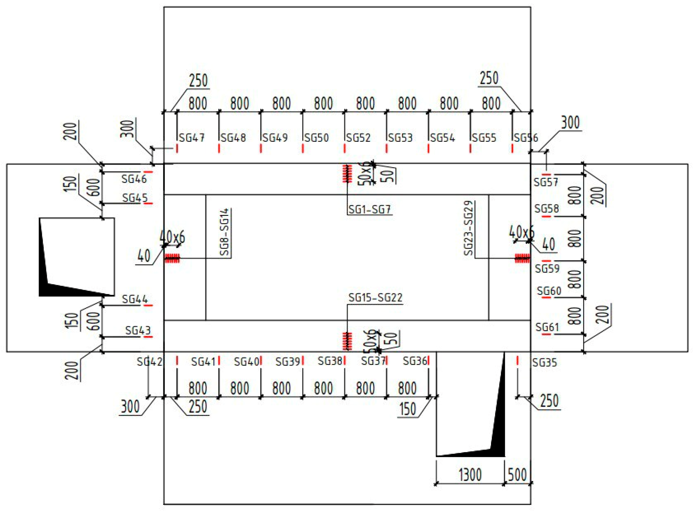
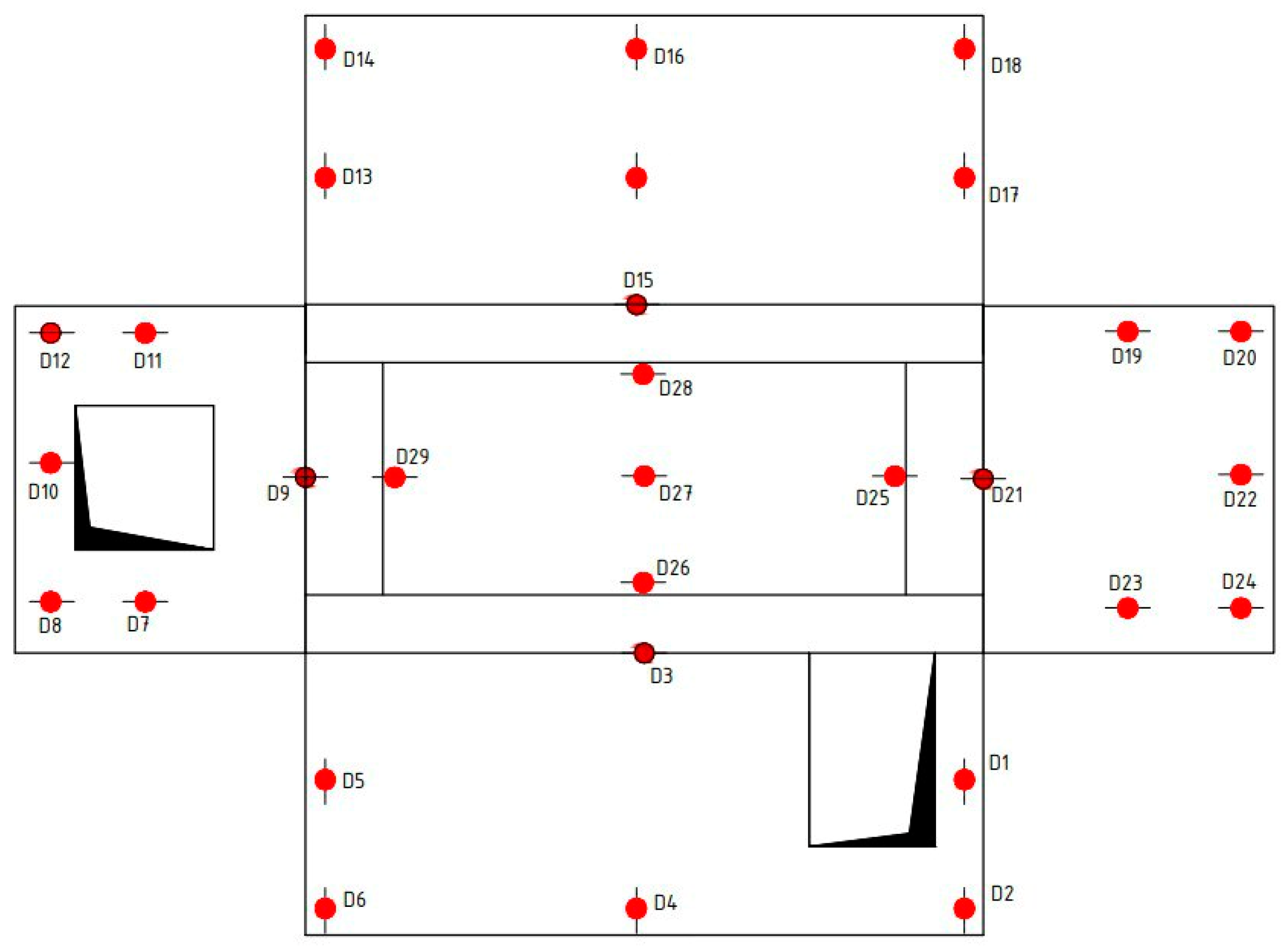
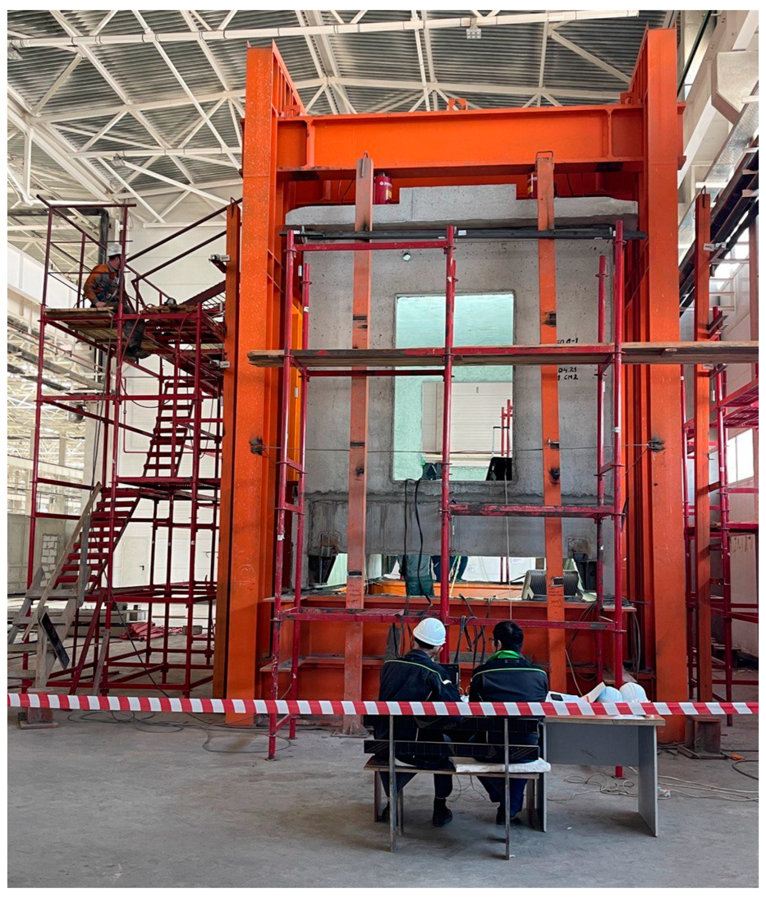
2. Materials and Methods

The technology of the ModeX Astana LLP plant (Astana, Kazakhstan) carries out the manufacture of volumetric blocks of the “lying glass” type with dimensions of 3480 × 6980 × 2980 mm, consisting of three walls, ceiling, and floor slabs. Volumetric blocks are completed in the plant with prefabricated load-bearing external wall panels. By design, buildings made of volumetric blocks are volumetric block buildings with internal single-layer walls and plug-in external walls of single-layer and three-layer designs. The building is completed from volumetric blocks supported on each other, having linear support on four sides through a layer of mortar. Volumetric blocks are made of concrete and expanded clay concrete and differ in reinforcement and presence of doors.
Volumetric blocks underwent testing on a specialized bench. This bench comprises a robust spatial metal rod framework with adjustable vertical and horizontal transverse frames. The volumetric block subjected to testing was positioned on the upper section of the frame floor beams, known as the stylobate, which includes reinforced concrete longitudinal and transverse beams with hinged support located on the lower portion of the power stand. Volumetric blocks are supported both in the building and in the test specimen by beams along the perimeter on a mortar seam. Stylobate reinforced concrete beams, fabricated from concrete of grade C20/25, exhibit variations in cross-sectional design and reinforcement. The beams are designed to withstand a testing load for vertical columns of volumetric blocks as seen in Figure 2.
The application of loading to the volumetric block was facilitated by hydraulic jacks. This arrangement ensured the imposition of a uniform compressive load along the length of the walls, with an eccentricity of 0.5 m modeling wind effects. Throughout the testing phase, horizontal and vertical displacements of critical sections were carefully recorded. To assess the compressive strains in the concrete, measurements were taken along the perimeter of the longitudinal walls and across the height of the compressed zone in the reinforced concrete stylobate beams. Concrete strains were measured using a strain gauge with a base of 50 mm and a division value of 10−6, attached to concrete surfaces, as well as an automatic strain gauge AID-4M (Figure 3 and Figure 4).
Furthermore, horizontal and vertical displacements of the elements were quantified using digital deflection indicators, specifically the MG-4 and PA0-6 models, with a division value of 0.01 mm (Figure 5).
To measure the vertical strains of the concrete walls of the specimen, strain gauges were attached at a height of 30 cm from the floor. These strain gauges had a division value of 10−6, and data from them were recorded on the strain gauge equipment. Horizontal displacements (deplanation of the volumetric blocks) and vertical deflections of the beams were also measured using a digital deflection indicator. The deflection indicator was mounted on 12 racks independently disconnected to the stand, with 3 deflection indicators on each rack. They were mounted on tripods beneath the horizontal beam structures. The opening width of the layers between the volumetric block and the stylobate beams was measured using PAO-6 deflectors with a division value of 0.01 mm [22]. The crack openings were measured with an MPB-3 microscope with a division value of 0.02 mm as seen in Figure 6.
The reinforced concrete beams on the frame floor were made of concrete C20/25. The beams had rectangular cross-sections: in the first type, longitudinal beams with a cross-section of 200 × 1000 mm and cross beams of 400 × 600 mm, and in the second type, longitudinal beams with a cross-section of 200 × 800 mm and cross beams with a cross-section of 200 × 500 mm. The beams were designed to withstand a load from a vertical column of volumetric blocks for 16- and 12-story residential buildings. The volumetric block under test was subjected to vertical loads from the overlying floors, which were created by a group of 10 hydraulic jacks with a capacity of 200 tons each. During the tests, the stress state of the walls of the volumetric block was assessed. The load of the volumetric block was carried out in steps equal to 5–7% of the expected destructive load.

3. Results and Discussion

Five full-scale volumetric blocks were tested and presented findings were carried out in continuation of the work on testing the blocks on a rigid base [1]. Specimens 1 to 5 differed in their design solutions, depending on the dimensions of the stylobate beams, concrete type, reinforcement, and presence of doors of the building they were intended for, as well as the structural changes made based on the test results of each specimen. These changes were made in response to the nature of the damage experienced by each specimen.

3.1. Experimental Volumetric Block M1

The experimental volumetric block denoted as M1, measuring 3480 × 6980 × 2980 mm, was fabricated using concrete of grade C20/25. The block maintained consistent thickness across both longitudinal and transverse walls, as well as the wall panel. Specifically, the longitudinal walls of the volumetric block possessed a thickness of 100 mm, while the transverse wall exhibited a thickness of 100 mm. A doorway with dimensions of 1300 × 2100 mm was provided in one longitudinal wall. The 120 mm thick wall panel had a window opening of 1750 × 1850 mm. The walls and floor slabs of the volumetric block were reinforced wire grids grade Ø4 and Ø5 Y500C (Bp-1), combined into a single spatial reinforcement block. The volumetric block under test was supported by longitudinal beams of the first type of stylobate with a cross-section of 200 × 1000 mm and transverse beams with a cross-section of 400 × 600 mm. The volumetric block was tested under a vertical load of 10 hydraulic jacks with a capacity of 1960 kN each, providing uniform wall compression (Figure 7).
In the first stage of the tests, three loading steps were applied up to a load of N = 4795 kN, corresponding to the characteristic vertical load. The mean compressive stresses experienced by the walls of the volumetric block measured 2.5 MPa, while the average compression strains within the concrete were in the range of (150–250) × 10−6 (Figure 8). The width of the crack above the doorway opening widened from 0.20 mm to 0.50 mm. Regarding deflections, the floor slab of the volumetric block exhibited values within the range of 0.92–1.66 mm. Notably, the most notable horizontal out-of-plane displacements, or deplanation, were observed in the longitudinal walls, ranging from 0.78 to 2.08 mm, with the end wall experiencing a displacement of 0.82 mm and the wall panel showing a displacement of 1.72 mm (Figure 9). In general, the results of these tests correspond to similar volumetric blocks supported by wall structures.
At the next stage of the tests, the walls of the volumetric block were loaded with an offset vertical load modeling the wind effects using 8 jacks, with 2 jacks shifted toward the end wall by 500 mm (Figure 10).
Under a vertical load of N = 1598 kN, cracks appeared in the longitudinal walls and the lintel above the doorway, with an opening width ranging from 0.05 to 0.10 mm. Concurrently, the mean compressive strain of the concrete on the longitudinal walls of the volumetric block was in the range of (200–270) × 10−6, while in the end wall and the wall panel, it remained below (50–60) × 10−6. The horizontal displacements of the longitudinal walls (deplanation) were 3–4 mm, and the transverse walls were 1.0–1.8 mm. Cracks up to 0.10–0.15 mm wide have formed in the reinforced concrete longitudinal beams in the stylobate.
Under a vertical load of N = 4103 kN, vertical cracks emerged in the lintels positioned above the door and window apertures, exhibiting an opening width ranging from 0.20 to 0.30 mm. Under a vertical load of N = 5347 kN, the layer between the volumetric block and the longitudinal beam in the stylobate cracked. After that, there was a surge in compressive strains on the walls of the volumetric block, an increase in horizontal and vertical displacements, and the formation and opening of cracks.
The structural failure of the volumetric block occurred under a vertical load of N = 10,462 kN, manifesting in the splitting of the ceiling slab, detachment of the end wall from the longitudinal wall, and the emergence of cracks in the floor slab, with an opening width of up to 5 mm. Simultaneously, the compressive strains experienced by the concrete on the longitudinal walls of the volumetric block were in the range of (460–500) × 10−6, while in the end wall, they were in the range of (150–260) × 10−6, and in the wall panel, they measured 400 × 10−6 (Figure 11). The gaps between the longitudinal walls and the stylobate beams were 0.20–0.25 mm, while the transverse walls were 0.12–0.14 mm, and the deflection of the floor slab was 2.57 mm (Figure 12). Figure 13 shows the largest horizontal displacements of the longitudinal walls (deplanation) of the volumetric block were 3.96–9.48 mm, the end wall was 11.04 mm, and the wall panel was 3.96 mm. The vertical cracks observed in the lintels positioned above the door and window apertures measured between 0.20 and 0.30 mm in width (Figure 14).

3.2. Experimental Volumetric Block M2

The experimental volumetric block M2 was made of expanded clay concrete LC20/22 with an average density of 1850 kg/m3. As shown in Figure 15, the block was installed on reinforced concrete stylobate beams with cross-sections of 200 × 1000 mm and 400 × 600 mm and tested for the combined effect of vertical loads and wind effects when two jacks were moved towards the end wall by 500 mm.
Under a vertical load of N = 1830 kN, cracks were formed in the longitudinal walls and the lintel above the doorway with an opening width in the range of 0.05–0.10 mm. At the same time, the average compressive strains in concrete in the longitudinal walls of the volumetric block ranged from 200 × 10−6 to 270 × 10−6, while in the end wall and the wall panel they did not exceed (50–60) × 10−6, i.e., (Figure 16), their ratio was in the range of 27–35% (Figure 17).
Cracks in stylobate reinforced concrete beams that had an opening width of 0.10–0.15 mm are presented in Figure 18 and Figure 19.
Under a vertical load of N = 4797 kN, the gap between the longitudinal wall with the doorway and under the longitudinal beam opened. The gap had an opening width of 1.5 mm, a length of 1150 mm (21.5%), and was in the middle part along the length of the walls. This caused a change in the ratio of compressive strains of the concrete along the length of the walls. This led to a sharp increase in strains and horizontal displacements and the formation and opening of cracks. The compressive strains of concrete on the longitudinal walls of the volumetric block were (400–650) × 10−6 and on the end wall and wall panel did not exceed (70–200) × 10−6. A grid of vertical cracks with an opening width of up to 0.15–0.20 mm was formed above the doors and window openings. Vertical and inclined cracks appeared in longitudinal walls up to 0.20 mm wide, as well as in a solid longitudinal wall up to 0.8 mm. Longitudinal and inclined cracks formed on the ceiling slab with an opening width of up to 0.15 mm. Figure 20 shows transverse cracks appeared in the floor slab of the volumetric block with a maximum width of 0.2 mm.
The opening of the gap between the walls of the block and the stylobate beams ranged from 0.30 mm to 0.50 mm, and the deflections of the floor slab were 6.56 mm. The opening of the gap between the longitudinal wall and the longitudinal beam under it is shown in a diagram of the longitudinal strains of the concrete on the longitudinal wall (Figure 21). At the initial stages of vertical loading, the longitudinal wall and the longitudinal beam under it worked together. Thus, at these loading stages, tensile strains were observed in the upper zone of the longitudinal beam with a value up to +600 × 10−6. With the opening of the gap between the longitudinal wall and the longitudinal beam, the tensile deformations in concrete are replaced by compressive strains, and the maximum compression strains reach values of −400 × 10−6.
The failure of the volumetric block occurred under a vertical load of N = 5754 kN and was accompanied by a split of the angular part of the lintel at the entrance of the longitudinal wall under a vertical change in the crack banks, and a crack opening of 1.5–2.0 mm is shown in Figure 22. The highest compressive strains in concrete in the extreme parts of the continuous longitudinal wall were in the range of (600–620) × 10−6, while in the middle part of the wall, they were 370 × 10−6. The maximum compressive strains in concrete in the extreme parts of the longitudinal wall with a doorway were in the range of (630–770) × 10−6 and in the middle part of the wall 390 × 10−6. The highest compression strains in the concrete of the end wall and panel were (360–370) × 10−6.
A vertical and inclined crack system with an opening width of 0.20–0.25 mm was formed on the entire surface of the lintel above the doorway. New vertical cracks appeared in the longitudinal walls and the crack in the solid longitudinal wall increased from 0.8 mm to 1.0 mm. New longitudinal cracks have formed on the ceiling slab, as well as transverse cracks on the floor slab. The width of the gap opening between the floor slab of the volumetric block and the longitudinal reinforced concrete beam on the stylobate increased to 2.0 mm.

3.3. Experimental Volumetric Block M3

The experimental volumetric block M3 was made of expanded clay concrete LC 20/22 with an average density of 1850 kg/m3 and has one door in the longitudinal wall and one door in the end wall. The block features two side walls with a ribbed structure, consisting of a 50 mm thick wall and 100 mm high ribs, alongside an end wall that is 100 mm thick. Additionally, the bottom slab of the block has ribs measuring 80 mm in height with 170 mm high ribs and is 97 mm thick, while the top slab is flat and measures 80–97 mm thick. The outer wall panels are 120 mm thick and consist of a layer of reinforced concrete, insulation, and a facade. Volumetric block M3 was installed on stylobate beams, on which volumetric blocks M 1 and M 2 were tested under combined vertical loads and wind effects, with two jacks being shifted by 500 mm towards the end wall (Figure 23).
Under a vertical load of N = 3109 kN (35% of the destructive load), the gap between the longitudinal walls of the volumetric block and the stylobate opened. The opening was 1.0 mm wide and approximately 500 mm long (7% of the longitudinal wall). At the same time, a longitudinal crack formed on the ceiling slab.
Under a vertical load of N = 5027 kN (57% of the destructive load), longitudinal and inclined cracks appeared on the ceiling slab, as well as a vertical crack in the lintel of the longitudinal wall (Figure 24). Under a vertical load of N = 6945 kN (78% of the destructive load), the opening width of the gap between the longitudinal walls of the volumetric block and the stylobate was about 2.0–2.5 mm wide and 1800 mm long (26% of the longitudinal wall length). A vertical crack formed in the solid longitudinal wall.
Under a vertical load of N = 6945 kN (78% of the destructive load), the opening width of the gap between the longitudinal walls of the volumetric block and the stylobate was 2.0–2.5 mm wide and approximately 1800 mm long (26% of the longitudinal wall of the block). At the same time, a vertical crack formed in the solid longitudinal wall.
Under a vertical load of N = 7973 kN (90% of the destructive load), a grid of longitudinal cracks was formed on the ceiling and floor slabs, inclined cracks in a solid wall, and vertical cracks in the lintels of the longitudinal end wall. Figure 25 shows the volumetric block failed under a vertical load of N = 8863 kN due to the splitting of the longitudinal wall lintel and a vertical shift of the crack banks.

3.4. Experimental Volumetric Block M4

The experimental volumetric block M4 was made of LC16/18 expanded clay concrete with an average density of 1850 kg/m3 and has one door on the longitudinal wall and one door on the end wall. The walls have a thickness of 50 mm and a height of 100 mm. Along with this, there is an end flat wall that measures 100 mm in thickness. The floor slab of the block has ribbing. It has a slab thickness of 80 mm and ribs that stand at a height of 170 mm. Conversely, the ceiling slab is flat and has a thickness ranging from 80 to 97 mm. External plug-in wall panels are 120 mm thick and consist of single layers. These layers include an expanded clay concrete bearing layer, effective insulation, and a hinged facade system as a facing layer.
The volumetric block was installed on reinforced concrete beams of the first type of stylobate and tested under the combined effect of vertical loads and wind effects when two jacks were shifted towards the end wall by 500 mm (Figure 23).
In the first stages of loading, there was an almost uniform distribution of longitudinal compressive strains in concrete along the perimeter of the volumetric block walls. With an increase in vertical load, a gradual acceleration of the increase in compressive strains is observed in concrete at the ends of the volumetric blocks. Under a vertical load of N = 959 kN (17% of the destructive load), cracks opened in the lintels of the longitudinal walls at a value of 0.35–1.00 mm, and in the lintels of the end wall and the wall panel with an opening width of 0.05–0.10 mm, as well as transverse cracks formed in the floor and ceiling slabs (Figure 26). With a further increase in vertical loading, a grid in the longitudinal walls and an envelope shape in the ceiling slab are created.
Under a vertical load of N = 3836 kN (68% of the destructive load), the opening of the gap between the longitudinal walls and the stylobate beams was 1.0 mm, and the length of this gap was 650 mm (9.3% of the longitudinal wall). Deformations in the compressive concrete zone of the longitudinal beams were in the range of (430–460) × 10−6.
Under a vertical load of N = 4795 kN, which is 85% of the destructive load, the failure of the lintels of the longitudinal walls was observed. The horizontal displacements (deplanation) of the longitudinal walls were 4.1–4.5 mm, the transverse wall was from 1.0 to 1.5 mm, and the wall panel was from 1.46 to 1.84 mm (Figure 27).
The volumetric block failed under a vertical load of N = 5626 kN, in which cracks formed in the horizontal gaps of the conjunction of the longitudinal walls with the coating slab, and the concrete of the longitudinal wall crumpled under the ceiling slab. The most significant compressive concrete strains in the longitudinal walls of the volumetric block reached (620–1000) × 10−6 and are presented in Figure 26 and Figure 28.
In the longitudinal beams of the stylobate, we measured (430–460) × 10−6; in the transverse beams of the stylobate, we measured (250–300) × 10−6. The width of the transverse crack in the ceiling slab reached 0.50 mm, in the longitudinal beams of the stylobate it reached 0.15–0.20 mm, and in the transverse beams, 0.10–0.15 mm; this is presented in Figure 29, Figure 30 and Figure 31.

3.5. The Experimental Volumetric Block M5

The experimental volumetric block M5 with dimensions of 3480 × 6980 × 2980 mm was made of expanded clay concrete CL16/18 with an average density of 1850 kg/m3 with a constant thickness for the longitudinal and transverse walls and wall panels. The longitudinal wall had a thickness of 100 mm. The end transverse wall, which had a thickness of 100 mm, had a doorway that measured 1300 × 2100 mm in one longitudinal wall. The thickness of the wall panel is 120 mm. The volumetric block has reinforced reinforcement in the form of V-shaped frames within its longitudinal walls and transverse ribs. It uses rods with a diameter of 8 mm, grade A500C. The ceiling slab on the volumetric unit is flat and has wall thicknesses between 80 and 97 mm. Additionally, there is an external wall panel that measures 120 mm in thickness and is made from expanded clay concrete.
The volumetric block was installed on reinforced concrete beams of the second type of stylobate (reduced cross-sectional dimensions). The combined effect of vertical loads and wind effects was further tested when two jacks were displaced towards the end wall by 500 mm, as shown in Figure 32. The reinforced concrete beams of the stylobate are made of concrete C20/25 and have longitudinal beams with a cross-section of 200 × 800 mm and transverse beams with a cross-section of 200 × 500 mm.
Already in the first stages of loading with vertical loading N = 2150 kN (25% of the destructive load), there is a significant unevenness in the distribution of longitudinal compression strains in concrete along the length of the walls of the volumetric block (Figure 33).
As shown in Figure 34, the gaps between the walls of the volumetric block and the stylobate beams begin to open. This is accompanied by a decrease in the area of support for the volumetric block on the stylobate beams.
The compressive stresses in concrete in the middle part of the walls become tensile stresses and the compressive stresses in the support zone shift to the supports and increase by 7–10%. The greatest expansion of the gaps occurs under the longitudinal walls, where the supporting part of the walls decreases by 5–7% of the length of the walls. A similar phenomenon is observed on the end wall and on the wall panel. The highest level of compressive stresses in concrete increases by almost 10% and cracks in wall lintels increase to 0.15–0.20 mm, as shown in Figure 35.
Under a vertical load of N = 3974 kN (47% of the destructive load), the opening of the gaps under the longitudinal walls reaches 1.2 mm. The supporting part of the walls has decreased by 10–12% in length, increasing the most significant compressive stresses in the concrete of the supporting parts of the beams by 15–17% and the width of the cracks in the walls by 40–50%.
Significant damage and deformations appeared in the volumetric block elements under a vertical load of N = 4932 kN (58% of the destructive load). The opening of the gaps under the longitudinal walls reaches 1.5 mm, the supporting part of the walls decreased by 20–22% of the length of the walls, and the compressive strains in the concrete of the supporting part of the beams were (130–170) × 10−6, the width of the cracks in the longitudinal walls was 0.45–0.52 mm. The deflections of the longitudinal walls were 9.94 mm and 13.14 mm, the deflections of the end wall were 6.32 mm, and the deflections of the wall panel were 4.88 mm (Figure 36 and Figure 37).
Under a vertical load of N = 7808 kN (92% of the destructive load), the deflections of the longitudinal walls were 9.94 mm and 13.14 mm, the deflections of the end wall were 6.32 mm, the deflections of the wall panel were 4.88 mm, and the deflections of the floor slab were 11.55 mm (Figure 38 and Figure 39).
The experimental block failed under a vertical load of N = 8776 kN and was caused by damage (split) to the lintel of the doorway of the longitudinal wall. Horizontal movements from the plane of the solid longitudinal wall (deplanation) of the volumetric block were within 2.8–4.4 mm; the longitudinal wall with a doorway of 4.9–10.6 mm, the end wall of 0.9–2.5 mm, and the wall panel of 1.0–3.4 mm are shown Figure 40.
An important feature of reinforced concrete volumetric blocks is the increased flexibility of the walls, which leads to a complex stress state aggravated by technological damage caused by overloads during manufacture, lifting, transportation, and installation. Therefore, experimental studies on the behavior of large-scale reinforced concrete volumetric blocks with different types of damage allow us to assess the impact of these technological defects. Additionally, they allow us to evaluate the consequences of damage under operational and destructive loading conditions and to identify the actual reserves of rigidity and bearing capacity of the volumetric blocks under various levels of external influence.

4. Conclusions

The presented experimental study on volumetric blocks based on frame floors in multi-story buildings considers the influence of the stiffness of reinforced concrete beams of the underlying floor on the stress state of volumetric blocks at different loading levels. Excessive deformations may affect the rigidity and strength of the walls of the blocks, leading to their premature failure due to the loss of stability.
To compare the strength of different volumetric blocks, the factor K2 is used, which is calculated by dividing the ultimate load N by the area of the horizontal cross-section of the block, minus openings, and concrete strength. In blocks of “lying glass” type with linear support along the perimeter, as used in the Soviet Union [23], the average value of K2 was approximately 0.41, according to research conducted by Kazakh Research and Design Institute of Construction and Architecture in 2020–2021 [24].
The test results of the volumetric blocks supported by pre-cast reinforced concrete stylobate beams differ significantly from those of similar volumetric blocks supported by a rigid base:
-
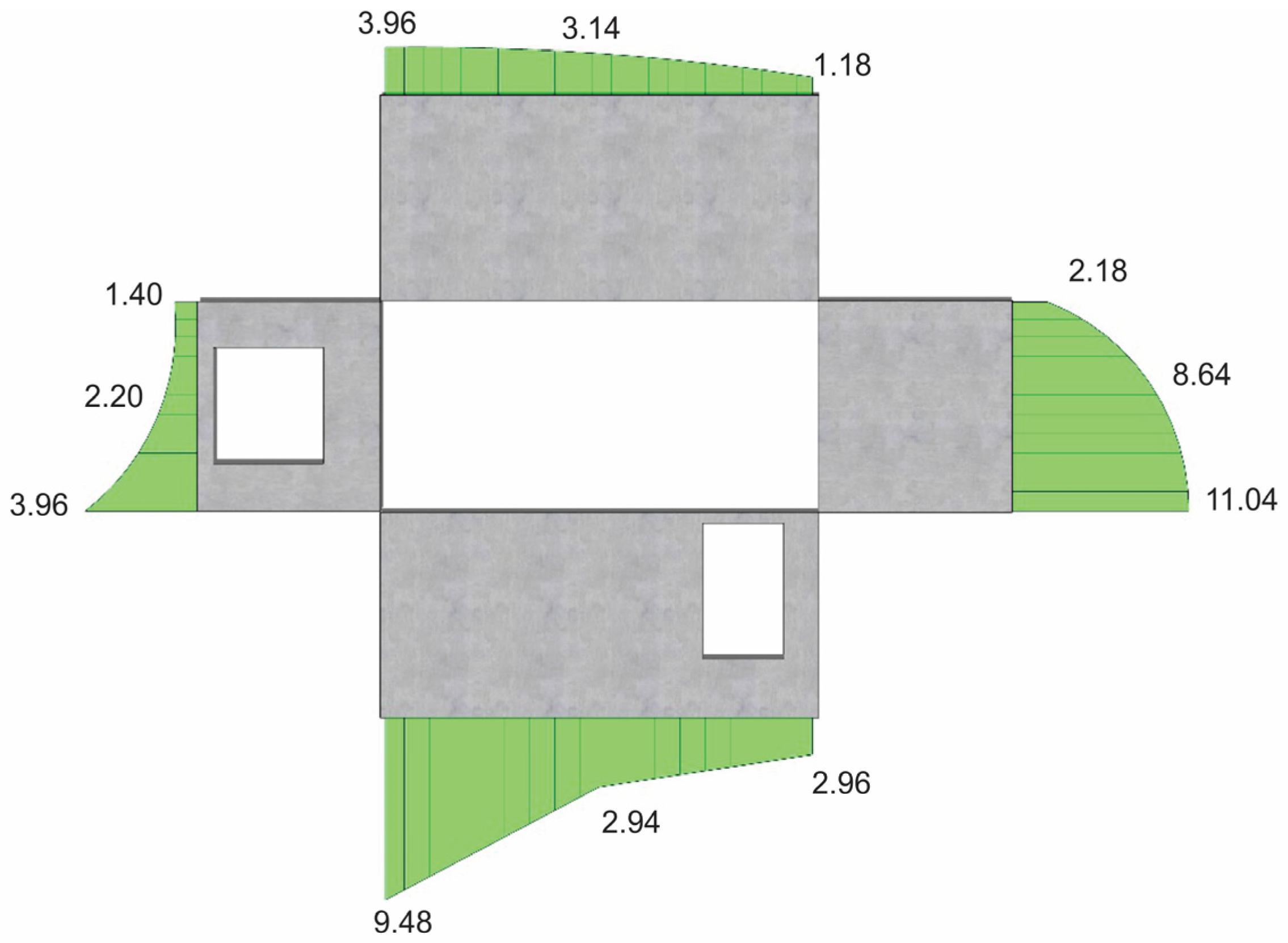
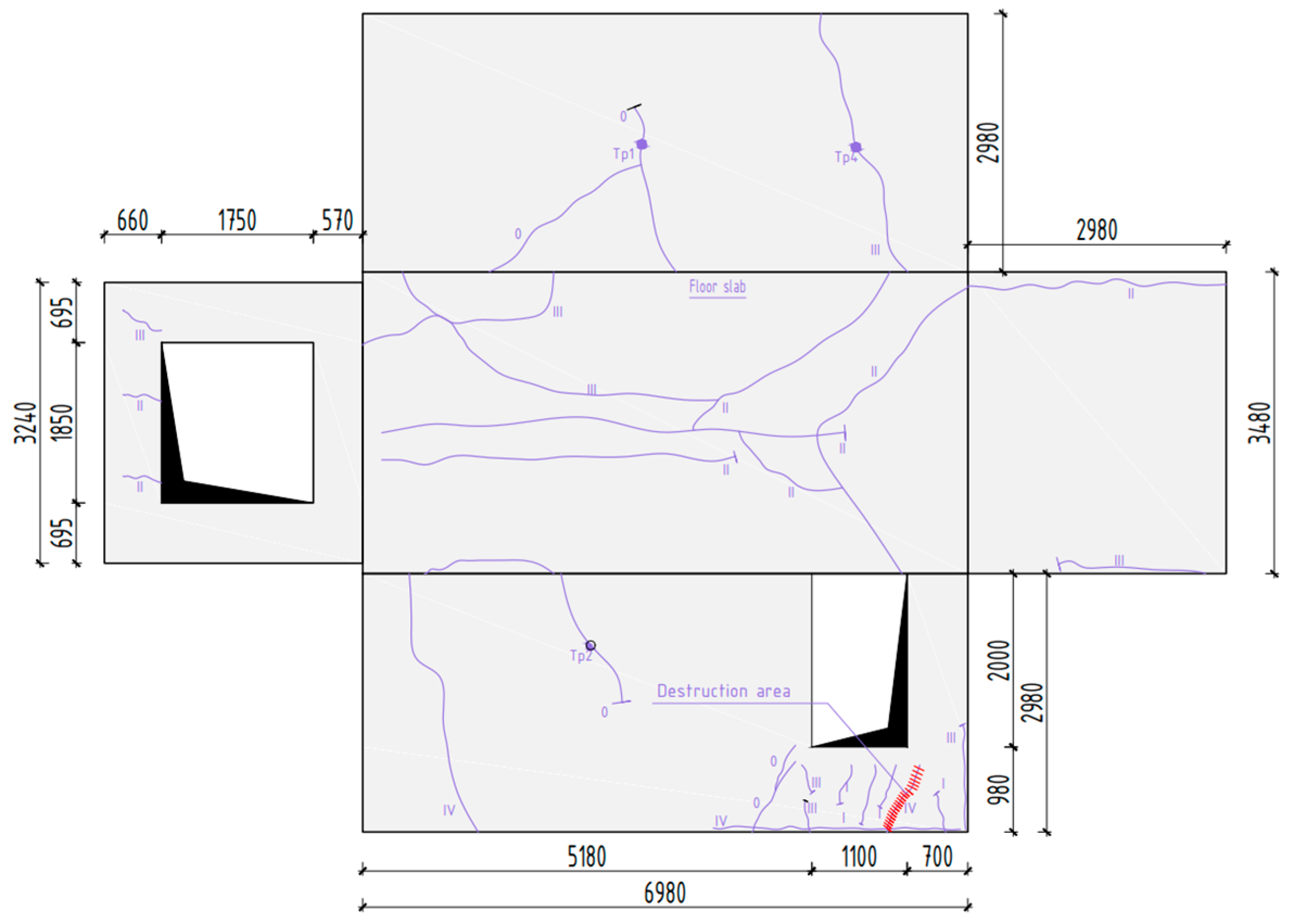
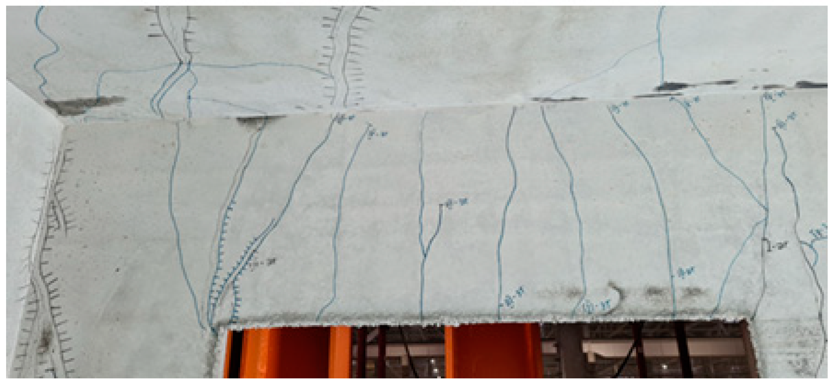
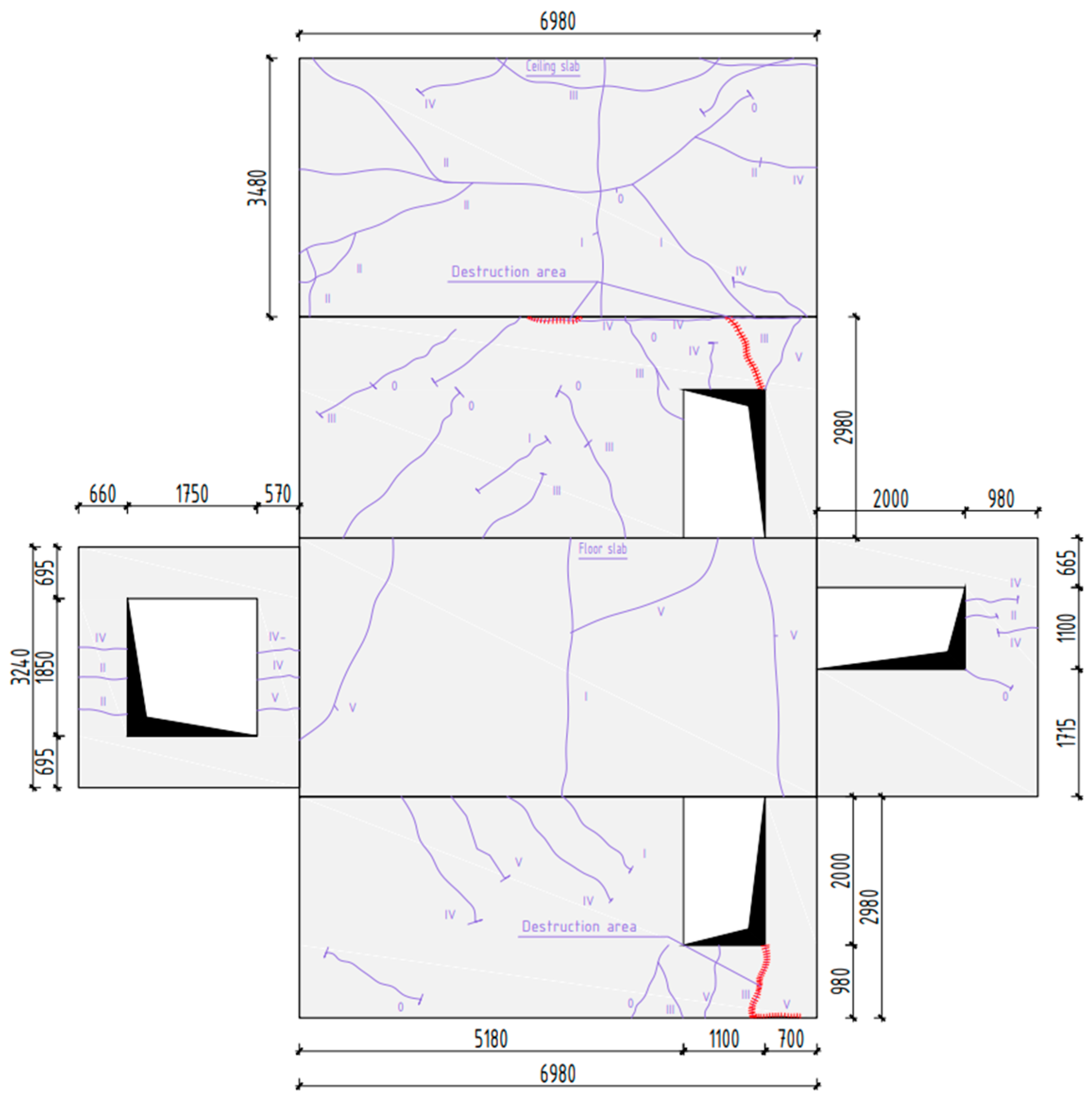
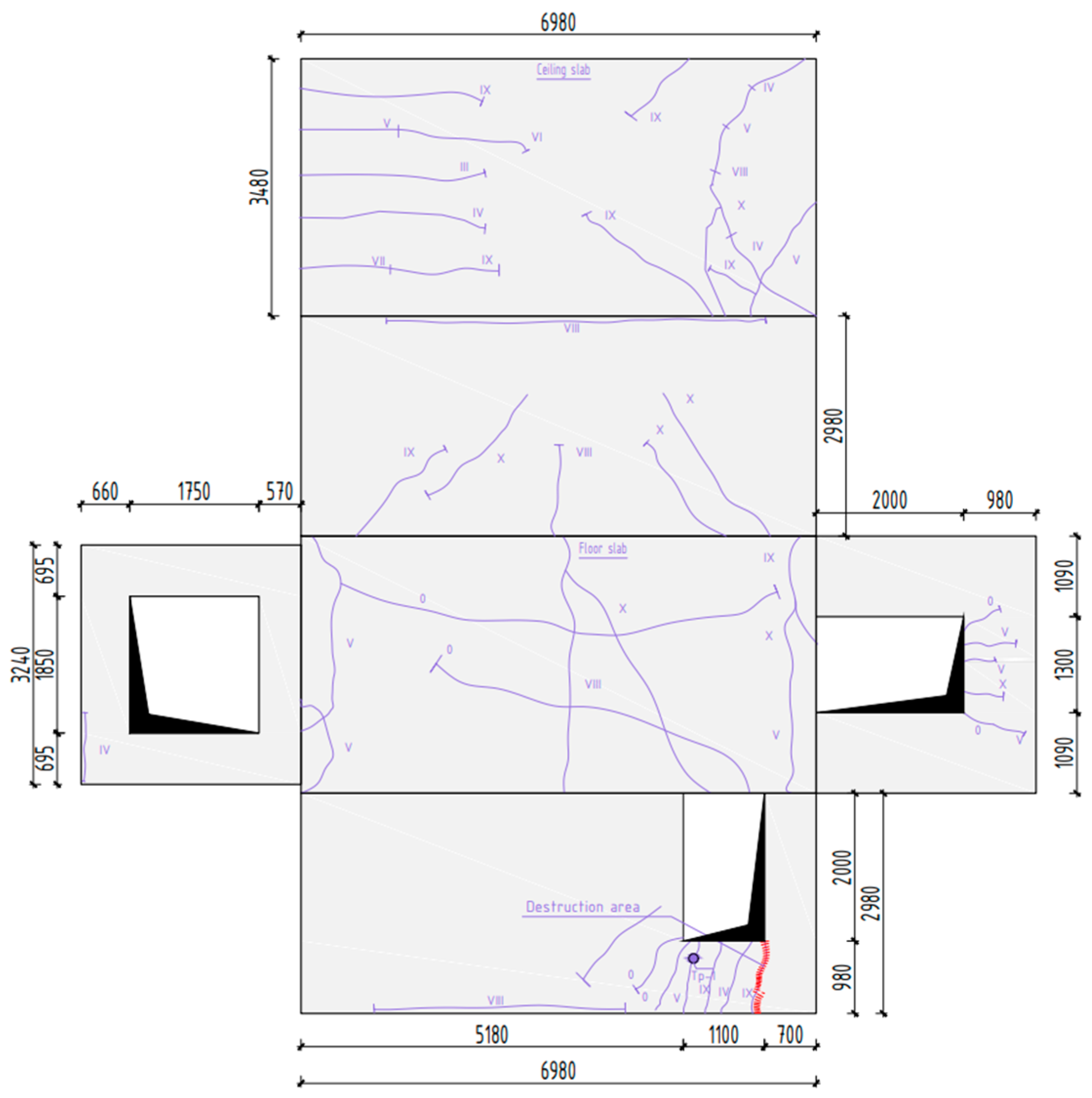
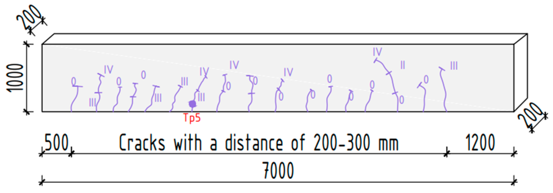
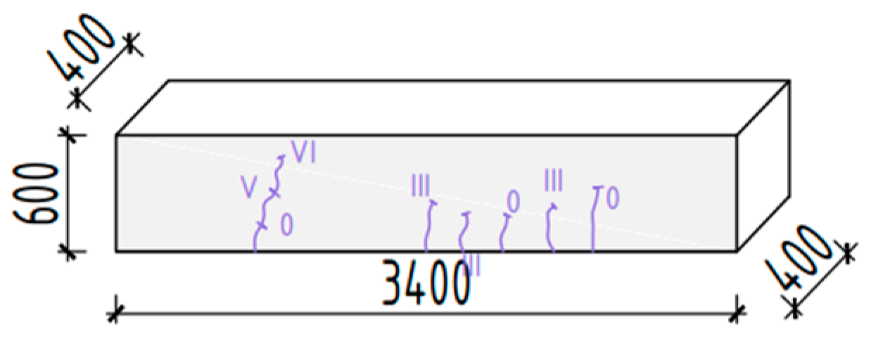
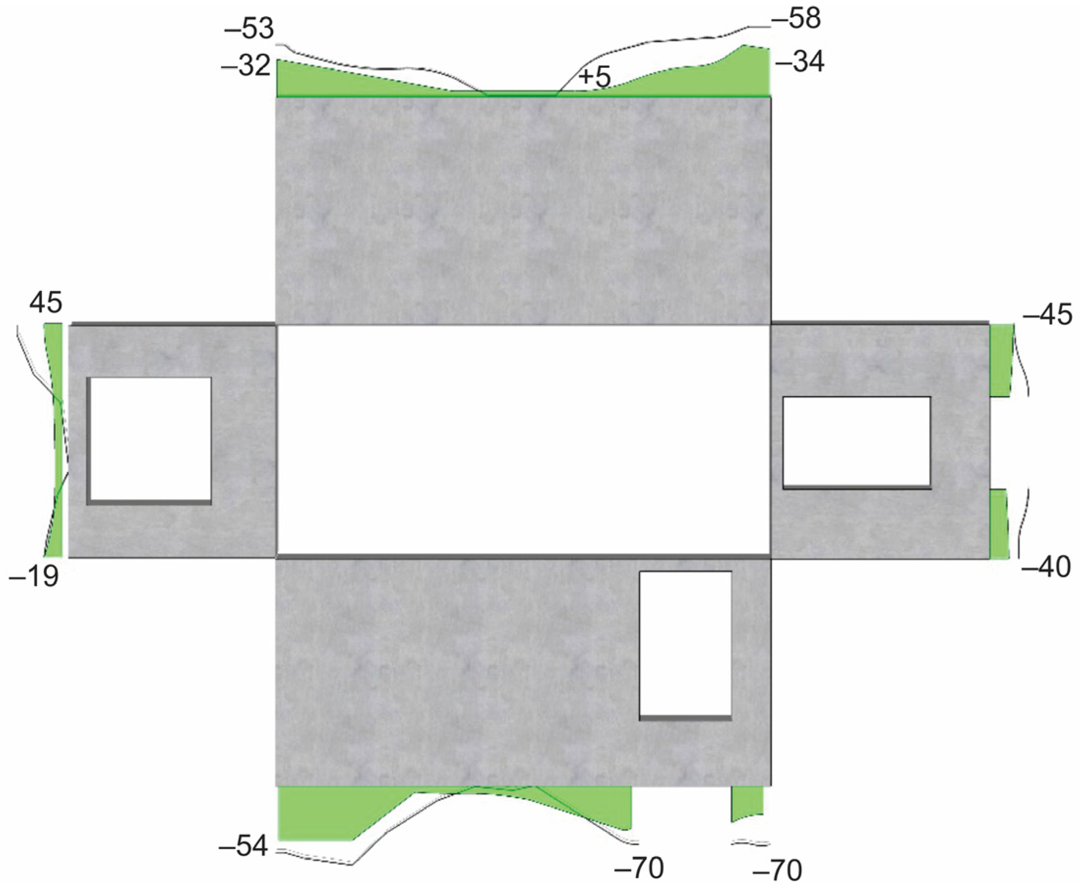
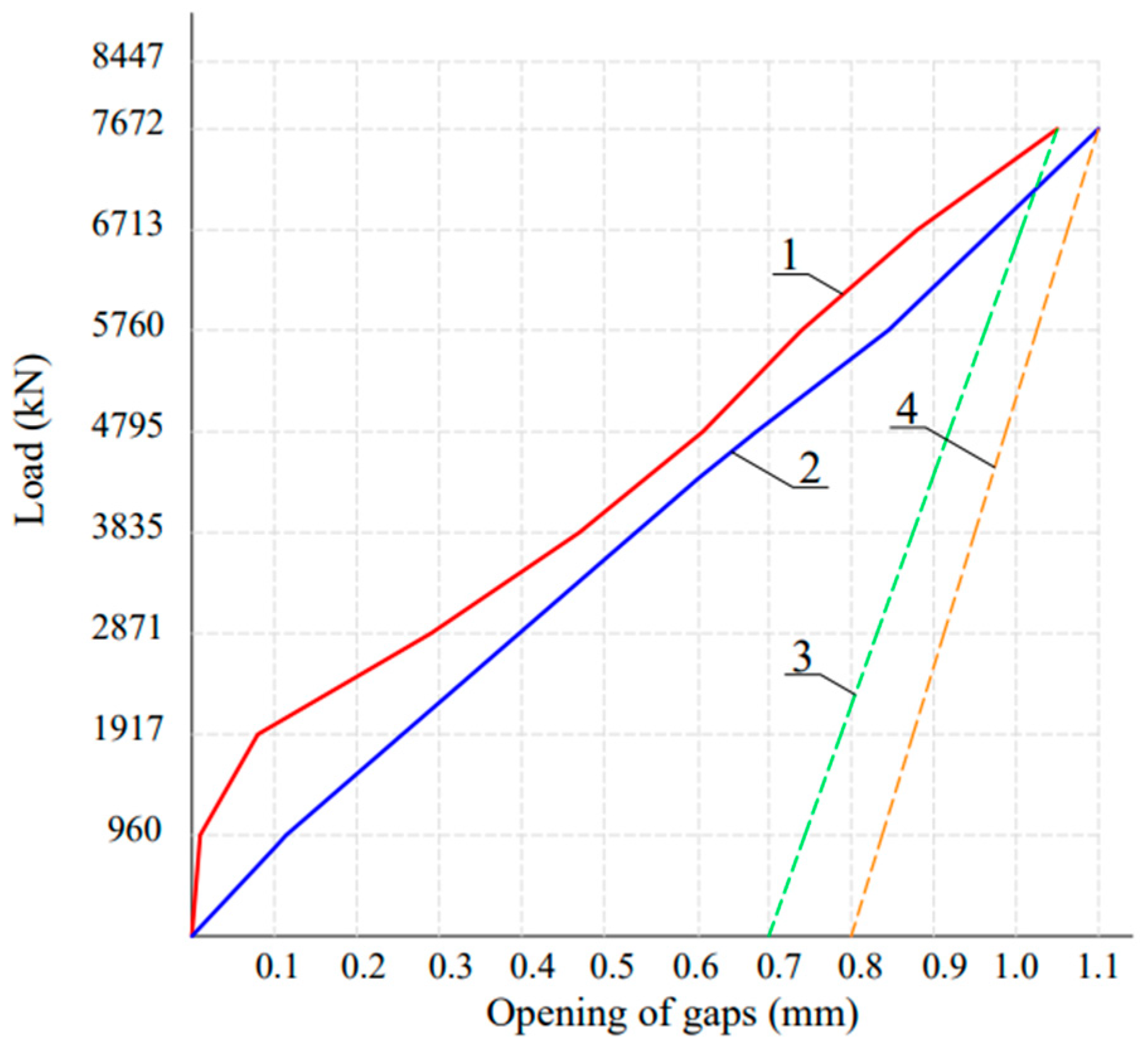
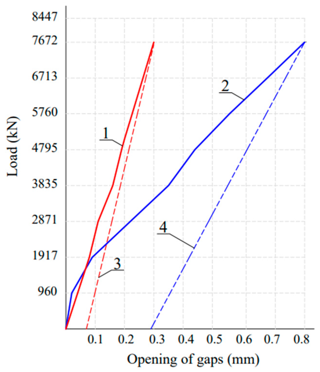
The formation and opening of the gaps between the floor slab of the volumetric block and the stylobate beams, cracks, as well as significant horizontal displacements of walls led to the decrease of the support zones of walls, which caused redistribution of the compressive stresses and an increase of their magnitude in the support zones.
-
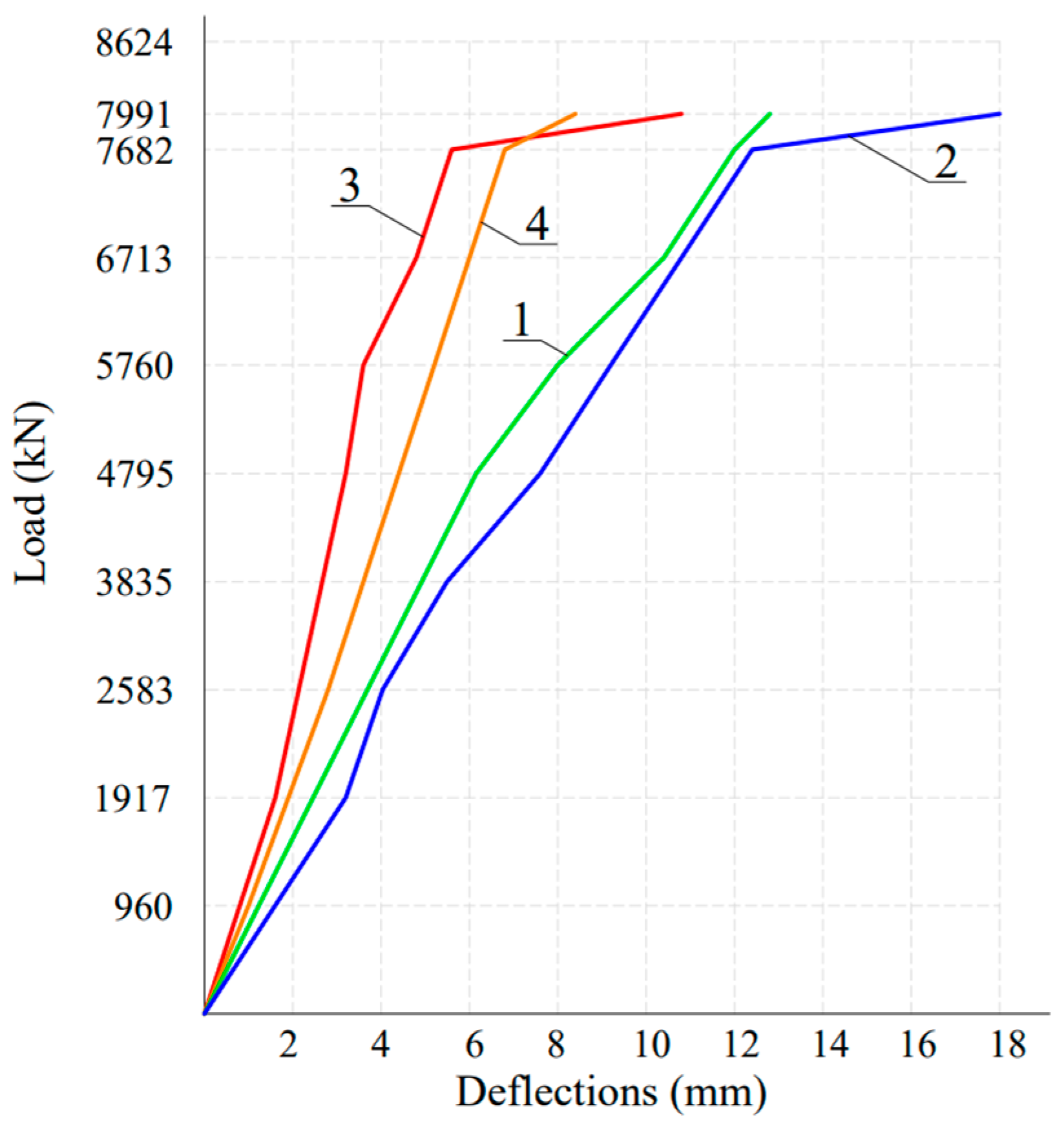
Cracks along with significant horizontal displacements (deplanation) of the walls decreased the stiffness of the conjunction of the longitudinal walls with the floor slab and created additional eccentricity of the longitudinal forces, which led to the increase of the slenderness of the walls and to the reduction in their bearing capacity.
Table 1 shows test data on the magnitude of cracks, horizontal displacements of walls, the support zone of longitudinal walls, and the coefficient K2, which shows a decrease in the bearing capacity of volumetric blocks when resting on flexible stylobate beams compared to those resting on wall structures.
Thus, in the case of placing the volumetric blocks on the frame floor, an up to 2.5 mm gap between the volumetric block and the slender beams occurs. The support area of the longitudinal walls decreases by 21.2%, the horizontal displacements of the walls increase by 13–18 mm, and the width of cracks in the lintels and walls increase by up to 0.5 mm. The strength of volumetric blocks placed on frames decreased by 23% as compared to those supported by walls or foundations.
The practical implication of this study is the selection of design solutions and optimization of the structure of volumetric blocks as well as the selection of materials for these blocks on flexible floors. The analysis of vertical strains allows us to determine the load-bearing capacity coefficient of these thin-walled structures, while the measurement of horizontal displacements helps to identify random eccentricities that need to be considered in the design of these structures. This information allows engineers to design optimal thin-walled, volumetric modular structures for different floors and building designs, taking into account technological aspects related to production, transportation, and installation. Additionally, analyzing the destruction zones helps to design the coupling of elements in a volumetric block in order to ensure maximum rigidity with respect to longitudinal walls and ceiling plates.

Author Contributions

Conceptualization, I.T. and Z.Z.; methodology, A.B.; software, T.Z.; validation, U.A. and A.T.; formal analysis, I.T. and A.T.; investigation, I.T.; resources, A.B.; data curation, T.Z.; writing—original draft preparation, A.T. and I.T.; writing—review and editing, M.T.; visualization, U.A.; supervision, A.B. and M.T.; project administration, Z.Z.; funding acquisition, I.T. All authors have read and agreed to the published version of the manuscript.

Funding

This research received no external funding.

Data Availability Statement

Data are contained within the article.

Conflicts of Interest

The authors declare no conflicts of interest.

References

  1. Bespaev, A.; Teshev, I.; Kuralov, U.S.; Altigenov, U.B. Strength and Deformations of Volume-Blocks. In Smart Geotechnics for Smart Societies; CRC Press: London, UK, 2023; pp. 2408–2412. ISBN 978-1-00-329912-7. [Google Scholar]
  2. International Educational Corporation; Auyesbayev, Y.T.; Sundetova, A.Z. International Educational Corporation History of Development of Block-Modular Construction: Wat to solve the Housing Problem. Bull. Kazakh Lead. Acad. Archit. Constr. 2023, 87, 154–162. [Google Scholar] [CrossRef] [PubMed]
  3. Annan, C.D.; Youssef, M.A.; El-Naggar, M.H. Effect of Directly Welded Stringer-To-Beam Connections on the Analysis and Design of Modular Steel Building Floors. Adv. Struct. Eng. 2009, 12, 373–383. [Google Scholar] [CrossRef]
  4. Steinhardt, D.A.; Manley, K. Adoption of Prefabricated Housing–the Role of Country Context. Sustain. Cities Soc. 2016, 22, 126–135. [Google Scholar] [CrossRef]
  5. Lawson, R.M.; Grubb, P.J.; Prewer, J.; Trebilcock, P.J. Modular Construction Using Light Steel Framing: An Architect’s Guide; The Steel Construction Institute: Berkshire, UK, 1999. [Google Scholar]
  6. Li, H.X.; Al-Hussein, M.; Lei, Z.; Ajweh, Z. Risk Identification and Assessment of Modular Construction Utilizing Fuzzy Analytic Hierarchy Process (AHP) and Simulation. Can. J. Civ. Eng. 2013, 40, 1184–1195. [Google Scholar] [CrossRef]
  7. Kildsgaard, I.; Jarnehammar, A.; Widheden, A.; Wall, M. Energy and Environmental Performance of Multi-Story Apartment Buildings Built in Timber Construction Using Passive House Principles. Buildings 2013, 3, 258–277. [Google Scholar] [CrossRef]
  8. Larsson, M.; Kaiser, A.; Girhammar, U. Multi-story modular manoeuvres—Innovative architectural stacking methodology based on three Swedish timber building systems. World Conf. Timber Eng. 2012, 4, 63–72. [Google Scholar]
  9. Hořínková, D. Advantages and Disadvantages of Modular Construction, Including Environmental Impacts. IOP Conf. Ser. Mater. Sci. Eng. 2021, 1203, 032002. [Google Scholar] [CrossRef]
  10. Khan, A.A.; Yu, R.; Liu, T.; Gu, N.; Walsh, J. Volumetric Modular Construction Risks: A Comprehensive Review and Digital-Technology-Coupled Circular Mitigation Strategies. Sustainability 2023, 15, 7019. [Google Scholar] [CrossRef]
  11. Ferdous, W.; Bai, Y.; Ngo, T.D.; Manalo, A.; Mendis, P. New Advancements, Challenges and Opportunities of Multi-Story Modular Buildings—A State-of-the-Art Review. Eng. Struct. 2019, 183, 883–893. [Google Scholar] [CrossRef]
  12. Abdul Nabi, M.; El-adaway, I.H. Modular Construction: Determining Decision-Making Factors and Future Research Needs. J. Manag. Eng. 2020, 36, 04020085. [Google Scholar] [CrossRef]
  13. Nguyen, T.D.H.N.; Moon, H.; Ahn, Y. Critical Review of Trends in Modular Integrated Construction Research with a Focus on Sustainability. Sustainability 2022, 14, 12282. [Google Scholar] [CrossRef]
  14. Tamov, M.M. Control Tests of the Loading of Volumetric Blocks of the New Series; Scientific Works of KubSTU, 2016, 6. Available online: https://ntk.kubstu.ru/data/mc/0027/1007.pdf (accessed on 2 May 2024).
  15. Teshev, I.D.; Korostelova, G.K. Space Block House Prefabrication. Sci. Tech. Ind. J. Hous. Constr. 2016, 3, 26–33. Available online: https://cyberleninka.ru/article/n/obemno-blochnoe-domostroenie/viewer (accessed on 1 June 2016).
  16. Sidik, A.F.; Paramita, B.; Busono, T. The Comparison of Energy Usage of Modular Housing Using Sefaira®. IOP Conf. Ser. Earth Environ. Sci. 2021, 738, 012019. [Google Scholar] [CrossRef]
  17. Košir, M.; Iglič, N.; Kunič, R. Optimisation of Heating, Cooling and Lighting Energy Performance of Modular Buildings in Respect to Location’s Climatic Specifics. Renew. Energy 2018, 129, 527–539. [Google Scholar] [CrossRef]
  18. Srisangeerthanan, S.; Hashemi, M.J.; Rajeev, P.; Gad, E.; Fernando, S. Review of Performance Requirements for Inter-Module Connections in Multi-Story Modular Buildings. J. Build. Eng. 2020, 28, 101087. [Google Scholar] [CrossRef]
  19. Lacey, A.W.; Chen, W.; Hao, H.; Bi, K. Structural Response of Modular Buildings—An Overview. J. Build. Eng. 2018, 16, 45–56. [Google Scholar] [CrossRef]
  20. Wang, Y.; Xia, J.; Xu, B.; Ma, R. Research on the Design and Mechanical Properties of New Modular Building Joints. IOP Conf. Ser. Earth Environ. Sci. 2019, 358, 052004. [Google Scholar] [CrossRef]
  21. Oleynik, P.; Efimov, V. Modeling Volumetric Block Types in Residential Building Construction. Appl. Sci. 2024, 14, 3565. [Google Scholar] [CrossRef]
  22. Yermakhan, Z. Testing of structural elements and units of reinforced concrete products, volume- modular structural system in prefabricated design. Res. Retr. Acad. Lett. 2023, 4, 169–187. [Google Scholar] [CrossRef]
  23. Vaisman, E.P.; Tuchnin, A.A. Static Studies of Volumetric Blocks of the “Glass” Type in Syzran/Bulk-Block Housing Construction in the USSR; TsNIIEP Housing: Moscow, Russia, 1967. [Google Scholar]
  24. Ilyenko, I.A. Production of Reinforced Concrete Products for Bulk-Block Housing Construction in the USSR; Overview of VNIIEMS: Moscow, Russia, 1979; Volume 8, p. 52. Available online: https://rusneb.ru/catalog/000199_000009_007631932/?ysclid=lwx2gfz587888841752 (accessed on 1 May 2016).
Figure 1. Scheme of the block “lying glass”.
Buildings 14 01655 g001
Figure 2. Scheme of an experimental facility with stylobate beams and a volumetric block (a) façade and (b) section: (1) PM-3 frame; (2) PM-2 frame; (3) jacks; (4) distribution slab; (5) test block; (6) secondary beam; (7) main beam; (8) frame PM-1; (9) base frame.
Buildings 14 01655 g002
Figure 3. Scheme of the load strain gauge on the walls of the volumetric block.
Buildings 14 01655 g003
Figure 4. Arrangement of strain gauge: (a) on the longitudinal beams of the stylobate; (b) on the transverse beam of the stylobate.
Buildings 14 01655 g004
Figure 5. Scheme of horizontal and vertical arrangement of deflection indicator.
Buildings 14 01655 g005
Figure 6. General view of the volumetric block tests.
Buildings 14 01655 g006
Figure 7. Scheme of volumetric block M1 with jacks along the perimeter of the walls.
Buildings 14 01655 g007
Figure 8. Concrete strain diagram for the longitudinal walls of a volumetric block: (1, 2) the middle part of the wall; (3, 4) the extreme part of the wall.
Buildings 14 01655 g008
Figure 9. Horizontal deformations (deplanation) of the walls of the volumetric block under a vertical load of N = 4795 kN, mm.
Buildings 14 01655 g009
Figure 10. Arrangement of hydraulic jacks modeling with wind effect.
Buildings 14 01655 g010
Figure 11. Concrete strains in longitudinal walls under a vertical load of N = 5347 kN: (1, 2) longitudinal wall; (3, 4) the extreme part of the longitudinal wall.
Buildings 14 01655 g011
Figure 12. The opening of the gap between the longitudinal walls and beams of the stylobate and the deflections of the floor slab: (1, 2) between the stylobate and the longitudinal walls; (3) deflections in the floor slab of the volumetric block.
Buildings 14 01655 g012
Figure 13. Horizontal displacements (deplanation) of the walls, mm.
Buildings 14 01655 g013
Figure 14. Crack scheme.
Buildings 14 01655 g014
Figure 15. Scheme of replacement jacks.
Buildings 14 01655 g015
Figure 16. Horizontal displacements of the walls: (1, 2) longitudinal walls; (3) end wall; (4) wall panel.
Buildings 14 01655 g016
Figure 17. Diagram of compressive deformations in walls: (1, 2) the extreme parts of the wall; (3) the middle part of the wall.
Buildings 14 01655 g017
Figure 18. Cracks in the longitudinal beam of the stylobate.
Buildings 14 01655 g018
Figure 19. Cracks in the transverse beam of the stylobate.
Buildings 14 01655 g019
Figure 20. Scheme of cracks in the volumetric block.
Buildings 14 01655 g020
Figure 21. Diagrams of concrete strains in the upper part of the longitudinal beam of the stylobate: (1, 2, 3, 4) the deformation of the strain gauges along the height of the beam during the maximum destructive load.
Buildings 14 01655 g021
Figure 22. Damage to the lintel above the doorway of the longitudinal wall doorway.
Buildings 14 01655 g022
Figure 23. Scheme of volumetric block M3 with jacks placement.
Buildings 14 01655 g023
Figure 24. Crack scheme in volumetric block M3.
Buildings 14 01655 g024
Figure 25. Failure of the longitudinal wall lintel with a change in the crack banks.
Buildings 14 01655 g025
Figure 26. Diagram of longitudinal deformations of concrete in the longitudinal wall of a volumetric block: (1, 2) the extreme parts of the longitudinal wall; (3, 4) the middle part of the longitudinal wall.
Buildings 14 01655 g026
Figure 27. Horizontal displacements (deplanation) of the walls, mm.
Buildings 14 01655 g027
Figure 28. Concrete strains in the walls of the volumetric block.
Buildings 14 01655 g028
Figure 29. Scheme of cracks in the volumetric block M4.
Buildings 14 01655 g029
Figure 30. Diagram of the location of cracks in the longitudinal beam of the stylobate.
Buildings 14 01655 g030
Figure 31. Diagram of the location of cracks in the transverse beam of the stylobate.
Buildings 14 01655 g031
Figure 32. Hydraulic jack scheme.
Buildings 14 01655 g032
Figure 33. Distribution of compressive deformations.
Buildings 14 01655 g033
Figure 34. Width of the opening of the gaps under longitudinal walls: (1, 2) between the stylobate and the longitudinal walls; (3, 4) residual cracks after removal of loading.
Buildings 14 01655 g034
Figure 35. Opening the width of the gaps under the end wall and the wall panel: (1) end wall; (2) wall panel; (3, 4) residual cracks after removal of loading.
Buildings 14 01655 g035
Figure 36. Deflections of the walls of the volumetric block: (1, 2) longitudinal walls; (3) end wall; (4) wall panel; (5, 6, 7, 8) residual cracks after removal of loading.
Buildings 14 01655 g036
Figure 37. Cracks in stylobate beams: (1, 2) longitudinal beams; (3, 4) transverse beams; (5, 6, 7) residual cracks after removal of loading.
Buildings 14 01655 g037
Figure 38. Walls deflections: (1, 2) longitudinal walls; (3) end wall; (4) wall panel.
Buildings 14 01655 g038
Figure 39. Deflections of the floor slab.
Buildings 14 01655 g039
Figure 40. Horizontal displacements from the wall plane.
Buildings 14 01655 g040
Table 1. Data of the results.
No of Volumetric BlockConcrete GradeCross-Sections of the Stylobate Beams, mmFailure Load,
N, kN
Length of the Support Zone of the Longitudinal Walls b/L,%Factor
K2
M1C20/251000 × 200 and 600 × 400 10,46276.00.313
M2LC20/221000 × 200 and 600 × 400598678.50.302
M3LC16/181000 × 200 and 600 × 400503074.00.332
M4LC20/221000 × 200 and 600 × 400886381.40.325
M5LC16/18800 × 200 and 500 × 200877684.00.321
Disclaimer/Publisher’s Note: The statements, opinions and data contained in all publications are solely those of the individual author(s) and contributor(s) and not of MDPI and/or the editor(s). MDPI and/or the editor(s) disclaim responsibility for any injury to people or property resulting from any ideas, methods, instructions or products referred to in the content.

