Article

Splitting Tensile Mechanical Performance and Mesoscopic Failure Mechanisms of High-Performance Concrete under 10-Year Corrosion from Salt Lake Brine

1
College of Civil Aviation, Nanjing University of Aeronautics and Astronautics, No. 29, Yudao Street, Nanjing 210016, China
2
College of Road and Bridge Engineering, Xinjiang Vocational and Technical University of Transportation, No. 478, Yongshun Street, Urumqi 831401, China
*
Authors to whom correspondence should be addressed.
Buildings 2024, 14(6), 1673; https://doi.org/10.3390/buildings14061673
Submission received: 1 May 2024 / Revised: 28 May 2024 / Accepted: 31 May 2024 / Published: 5 June 2024
(This article belongs to the Special Issue Recent Advances in Technology and Properties of Composite Materials)

Abstract

:
In regions characterized by the challenging combination of brine corrosion in the salt lakes and river sand with alkali silica reaction (ASR) activity in areas of the Northwest, high-performance concrete (HPC) formulated with high-volume composite mineral admixtures as ASR suppression measures has been preferred for civil engineering structures in the region. This study investigates the splitting tensile strength, corrosion products, microscopic structure characteristics, and mesoscopic mechanical mechanisms of splitting failure of such HPC under 10-year corrosion from salt lake brine. The relationship between mechanical properties and corrosion damage, as well as the characteristics of internal crack propagation paths and failure mechanisms of HPC under splitting load, are explored. The findings reveal that as the alkali content within HPC rises, corrosion damage intensifies, resulting in a reduction in splitting tensile strength. Moreover, a linear association between mechanical properties and corrosion damage is observed. Microscopic structural analysis and numerical simulation of the splitting failure process of HPC elucidate that while the substantial presence of mineral admixtures effectively suppresses the ASR risk associated with alkali-reactive aggregates in concrete, uneven ASR gel products persist. These discontinuous micro-fine interface cracks induced by the gel products and the cracks induced by the gel products around the selective alkali-active aggregate particles distributed in the local area are the initiation sources of mortar cracks in HPC splitting failure. In terms of the overall failure state observed during the concrete splitting process, mortar cracks manifest two distinct extension paths: along the coarse aggregate interface and directly through the aggregates themselves. Notably, a greater proportion of coarse aggregates are directly penetrated by mortar cracks, as opposed to the number of interface failures bypassing coarse aggregates. More importantly, the above work establishes a theoretical reference in three dimensions: macroscopic, mesoscopic, and microscopic, for studying concrete corrosion damage in complex environments such as salt lake brine corrosion and ASR inhibition.

1. Introduction

Since the advent of cement concrete in the 19th century, the durability of concrete has become a technical issue in the engineering field. Due to its complexity, durability has become a challenging problem and a hot topic of research for scholars [1,2,3]. Tan et al. [4] proposed that factors affecting the durability of concrete can generally be categorized into carbonation, sulfate corrosion, ASR, freeze–thaw cycles, coupling effects of two factors (such as chloride–sulfate coupling, chloride–freeze–thaw coupling, sulfate–freeze–thaw coupling, sulfate corrosion–ASR coupling, etc.), and coupling effects of three factors or more. The areas of Northwest China belong to a high-salinity area with a salt content reaching as high as 347.2 mg·L−1, including sodium, potassium, magnesium sulfate, chloride, carbonate, and other salts [5]. These salts are the main components of brine and cause damage to the durability of concrete. Considering the presence of alkali-reactive sand in the study area, concrete is not only subjected to brine corrosion but also affected by ASR. Therefore, studying the damage and durability of concrete containing ASR inhibition measures under salt lake brine corrosion is of great significance for providing a theoretical reference to reduce corrosion and improve concrete durability.
An ASR has adverse effects on the durability, stiffness, permeability, strength, and aesthetics of concrete. Severe ASR can lead to concrete expansion and cracking, significantly impacting the service life of concrete. Effective measures are required to mitigate the ASR and corrosion of concrete to improve its service life. P. Venyite [6] found that the ASR in granite-based aggregates has a minimal effect on concrete damage. However, aged granite contains a significant amount of alkali-reactive minerals such as pyroxene and biotite, making it susceptible to ASR. Therefore, using granite as coarse aggregate can effectively reduce alkali aggregate reactions. Ebrahim Ghiasvand et al. [7] observed that the occurrence of ASR can cause changes to the mechanical properties of concrete due to the development of delayed cracks. R.A. Kadhim [8] encapsulated concrete cylinders with carbon fiber-reinforced polymers, effectively limiting the damage of the ASR concrete and reducing crack formation, significantly increasing concrete strength. Al-Rousan R. Z. [9] used external fiber-reinforced plastics (FRPs) with obvious dissipation of nodal energy to address the damage to reinforced concrete beam-column joints caused by ASR, greatly improving the maximum stress-bearing capacity of the joints and reducing the damage caused by the ASR. Through a comprehensive analysis of the above research results, it was found that although methods such as adding special aggregates and fibers [10] to improve the mechanical properties of concrete to suppress ASR can alleviate their effects on concrete, they are still worthy of consideration in terms of economy and practicality. To overcome these issues, scholars [11,12] proposed composite mineral inhibition measures composed of readily available and low-cost materials such as silica fume, ground granulated blast furnace slag, and fly ash and verified their inhibitory effects. This study also adopts these ASR inhibition measures.
In the Qinghai area, salt water corrosion is mainly caused by sulfate corrosion. The mechanism involves the formation of ettringite (AFt, 3CaO·Al2O3·CaSO4·12H2O) and gypsum (CaO·SiO2·CaCO3·CaSO4·15H2O) from the reaction of sulfates with calcium in cement hydration products [13]. These corrosion products lead to concrete expansion, significantly affecting concrete durability. To investigate the damage to concrete structures caused by sulfate corrosion products and to obtain a damage model, scholars have conducted extensive research and achieved rich results. Yu et al. [14] studied the durability of C50 and C60 concrete under sulfate and chloride (5% Na2SO4 + 10% NaCl) solution erosion, establishing a damage evolution equation for concrete in sulfate solution, reflecting the functional relationship between the relative dynamic modulus of elasticity (Er) of concrete and immersion time and sulfate concentration, using Er to characterize the degree of damage. Zhang et al. [15] conducted concrete expansion experiments in solutions of different concentrations of sulfate and chloride, proposing a theoretical expansion model for predicting stress, strain, and volume expansion during sulfate attack. Based on this model, a quantitative parameter (dimensionless factor D) for micro-cracks in concrete was proposed, indicating that the dimensionless factor D can characterize micro-cracks caused by combined sulfate and chloride corrosion. N. Cefis [16] calculated the mechanical response of materials to chemical expansion using a porous elastic damage model and established a functional relationship between concrete effective stress and total strain (ε), isotropic damage (D), and tensor characteristics of the homogenized skeleton’s elastic properties (d). Zhang et al. [17] also established a transport model of coupled nonlinear partial differential equations of chloride ions and sulfate ions in concrete and obtained numerical solutions using the finite difference method. Zhou [18] proposed that the damage variable (D) be defined as the function of plastic strain (ω). By considering the strain rate as an environmental factor and applying the proposed method, Lu [19] developed a stress–strain strain rate constitutive model of concrete to describe the plastic flow caused by the combined action of stress and strain rate. Li et al. [20] studied the damage to Reactive Powder Concrete (RPC) macroscopic mechanical properties caused by ion corrosion and established a damage constitutive model for ion corrosion under load coupling: the relationship between the damage variable “D” and the damage depth “e”. The reliability of the model was verified through different experimental and simulation data, showing that the corrosion depths after 90 days of chloride ion and sulfate ion corrosion were 13.32 mm and 11.30 mm, respectively. This demonstrates that chloride ion corrosion is more severe than sulfate ion corrosion, proving that the model can well describe the deformation characteristics of RPC under various conditions and provide a theoretical basis for calculating corrosion depth.
In summary, sulfate corrosion has different degrees of influence on the mechanical properties of concrete, thereby affecting its durability. However, the research results mentioned above regarding the relationship between damage and mechanical properties rely on specific parameters such as a dimensionless factor (D) and isotropic damage, while there are few models to study the relationship between damage and mechanical properties by using the dynamic elastic modulus (Er) of concrete. Meanwhile, the durability of concrete is particularly affected by its tensile strength, as tensile cracks [21]. Theoretically, there is a relationship between the dynamic modulus of elasticity and the strength of concrete, and the relative dynamic modulus can also reflect internal damage in concrete. Therefore, based on the above theory, using the relative dynamic modulus to characterize internal damage and studying the relationship between the relative dynamic modulus and splitting tensile strength provides a theoretical reference for researching corrosion damage in macroscopic and microscopic dimensions.
In this study, HPC of C50 and C60 was designed with six mix ratios incorporating three alkali contents, an air-entraining agent (a), a rust inhibitor (Z), and the addition of silica fume, ground granulated blast furnace slag, and fly ash. The specimens were immersed in simulated brine consistent with the main chemical components of actual salt lake brine for 10 years. Er and splitting tensile strength were systematically tracked and tested over various durations, elucidating the evolution of macroscopic mechanical properties with immersion time. Furthermore, micro-corrosion product X-ray diffraction (XRD) analysis and microstructure examination via SEM-EDS (scanning electron microscope energy dispersive spectroscopy) images were conducted to delve into the micro-damage characteristics of HPC. Er served as a pivotal metric for characterizing the extent of corrosion damage, enabling the derivation of a relationship model between Er and mechanical properties. Building upon this foundation, the propagation characteristics and failure mechanism of internal cracks in HPC under splitting tensile load were meticulously analyzed by employing a 3D random aggregate mesoscopic model.

2. Materials and Methods

2.1. Raw Materials

2.1.1. Binding Materials

The cement used in this study was ordinary Portland cement (P.O42.5) produced by Gansu Qilian Mountain Cement Group Co., Ltd. (Lanzhou, China). It contains chemical components such as SiO2, Al2O3, CaO, and Fe2O3, with a SiO2 content of 20.96%, a CaO content of 59.43%, and an Al2O3 content of 9.36%. The basic physical and mechanical properties of the cement are detailed in Table 1.
The experiments utilized Grade I fly ash (FA) from Gansu Yongdeng Lian Electric Fly Ash Co., Ltd. in Lanzhou, China, with a fineness of 9.0% retained on a 0.045 mm square-hole sieve. S95 grade ground granulated blast furnace slag (GGBFS) was obtained from Gansu Xiangyang Trading Co., Ltd. in Lanzhou, China. Silica fume (SF) was sourced from Qinghai Blue Sky Environmental Technology Co., Ltd. in Xining, China. The equivalent alkali content of the binding materials is calculated and presented in Table 2.

2.1.2. Aggregates

The fine sand used in this experiment was provided by a sand and gravel field in Ledu, Qinghai Province, with a fineness modulus of 2.87, belonging to medium sand and meeting the grading requirements of Zone II. Its apparent density is 2648 kg·m−3, bulk density is 1639 kg·m−3, void fraction is 38.1%, and clay content is 5.4%. The coarse aggregate consisted of crushed granite stones (5–20 mm) from a sand and gravel field in Xiaoxia, Xining. It has an apparent density of 2680 kg·m−3, a bulk density of 1535 kg·m−3, a void fraction of 42.7%, a clay content of 0.8%, and a crushing value of 8.0%. According to Bishnu’s idea of drawing a gradation curve [22], the aggregate grading curve was drawn as shown in Figure 1. According to national standards, the 14-day expansion rates of the fine and coarse aggregates measured by the rapid mortar bar method were 0.121% and 0.008%, indicating the risk of alkali activity in the fine aggregates.

2.1.3. Admixtures and Water

The high-performance water-reducing agent, air-entraining agent, and FDN steel reinforcement rust inhibitor were provided by Xining Yangjian Waterproof Admixture Co., Ltd., Xining, China. Among them, the PJ-FDN polycarboxylic acid high-performance water-reducing agent is a liquid with a solid content greater than 9.5% and a water reduction rate of 25%. The air-entraining agent is a liquid mainly composed of rosin thermopolymer. The rust inhibitor is also a liquid mainly composed of calcium nitrite, with a solid content of 30%. Tap water from Qinghai City, which meets national standards, was used for mixing.

2.2. Concrete Mix Proportion Design

Two different strength grades of concrete, C50 and C60, were designed for this experiment, incorporating ASR suppression measures through mineral admixtures. For C50, 12% FA, 20% GGBFS, and 3% SF were added, with a total mineral admixture content of 35%. For C60, 15% FA, 22% GGBFS, and 3% SF were added, with a total mineral admixture content of 40%. Additionally, the air-entraining agent (a) and rust inhibitor (Z) were included in both mixtures. To investigate the effect of alkali content on the mechanical properties of concrete under saltwater corrosion, according to the calculation process of the equivalent alkali content for cement in Table 2, three alkali content levels were designed for each strength grade of concrete: specimens with an original NaOH alkali content ranging from 0.6% to 0.8% were denoted by -0 (considered a low alkali state). Specimens labeled as -1 had an alkali content ranging from 1.3% to 1.4%, denoted as a medium alkali state, while specimens labeled as -2 had an alkali content ranging from 1.8% to 1.9%, referred to as a high alkali state in Table 3.
To analyze the effects of air-entraining agents and a rust inhibitor on the mechanical properties of HPC, this study experimentally designed three different admixture scenarios for C50: separately adding air-entraining agents, a rust inhibitor, and both simultaneously. Additionally, considering the influence of strength grades on the mechanical properties of HPC, experiments were conducted on C60 with proportions of air-entraining agents and a rust inhibitor added. The material proportions and alkali content for each concrete mix are shown in Table 3. To ensure the accuracy of the test results, test specimens of dimensions 100 mm × 100 mm × 515 mm (prisms) were prepared. Three parallel test specimens were prepared for each mixture, resulting in a total of 36 specimens.

2.3. Corrosive Environment

This experiment utilized and analyzed the chemical composition data of underground brine samples from the research area to prepare a high-concentration brine corrosion medium that matched the main chemical components of the samples. This medium was used as a simulated test environment, and its chemical composition is listed in Table 4. The formed concrete specimens were completely immersed in this environment for 10 years, and comprehensive test data were obtained.

2.4. Testing Methodology

2.4.1. Ultrasonic Testing for Corrosion Damage—Flat Measurement Method

Ultrasonic testing is utilized to determine the internal corrosion damage of concrete. It measures the time “t” and spacing “l” of ultrasonic waves, from which the ultrasonic velocity “v” can be inferred. Based on the ultrasonic pulse velocity testing method, the dynamic elastic modulus “E” of concrete can be tested in non-destructive test specimens [23] (as shown in Equation (1)).
E = ρ 1 + v 1 2 v 1 v V 2
where “E” is the dynamic elastic modulus of concrete, “ρ” is the density of concrete, “ν” is the Poisson’s ratio of concrete, and “V” is the ultrasonic wave velocity of concrete. A. N. Ababneh [24] suggests that the parameters “ρ” and “ν” of concrete material remain relatively constant and can be considered constants. Therefore, through calculation, Equation (2) yields the Er of concrete.
E r = E t E 0 = V t 2 V 0 2
where Er is the relative dynamic elastic modulus, E0 is the dynamic elastic modulus before immersion in brine, Et is the dynamic elastic modulus at a certain immersion time “t” in brine, V0 is the ultrasonic velocity before immersion in brine, and Vt is the ultrasonic velocity at a certain immersion time “t” in brine.

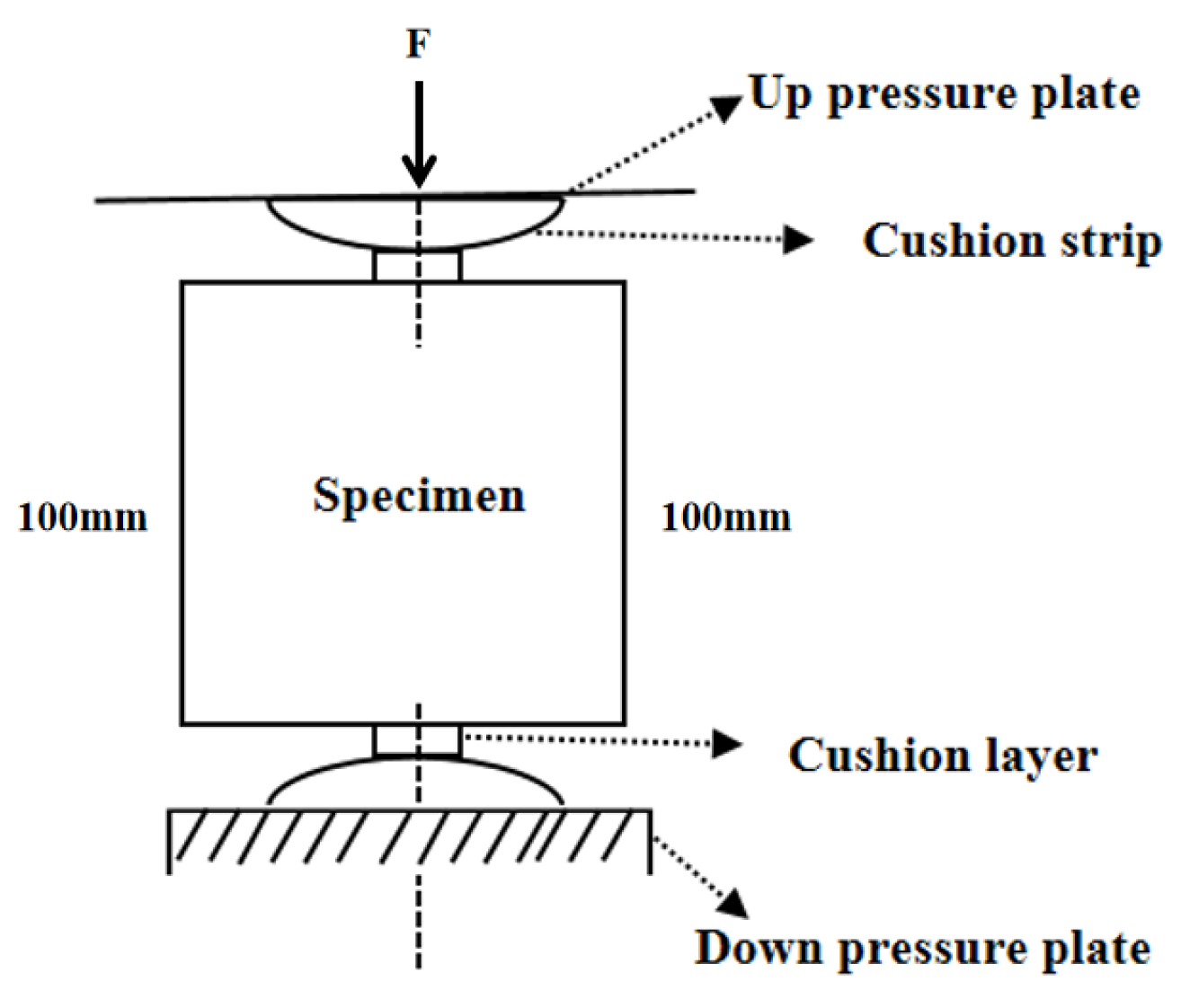
2.4.2. Split Tensile Test of HPC

Concrete is a brittle material that tends to crack under tension with minimal deformation. The tensile strength characterizes the concrete’s resistance to cracking, making the study of tensile strength significant. Cubic specimens after flexural strength testing, were subjected to split tensile testing. The YAW 4306 microcomputer-controlled electro-hydraulic servo pressure testing machine made by Meters Industrial Systems (China) Co., Ltd. in Shanghai, China, with a range of 3000 kN applies force F on the specimen along the midline between two opposing surfaces, as illustrated in Figure 2. The calculation of test results is presented in Equation (3).
f s t = 2 F π A = 0.637 F A
where fst is the splitting tensile strength of concrete (MPa), F is the failure load of the specimen (N), and A is the cross-sectional area of the specimen (mm2). In order to avoid the influence on the experimental results caused by the non-standard size, the splitting tensile strength measured by non-standard specimens (100 mm × 100 mm × 100 mm) should be multiplied by the size conversion coefficient of 0.85 [25].

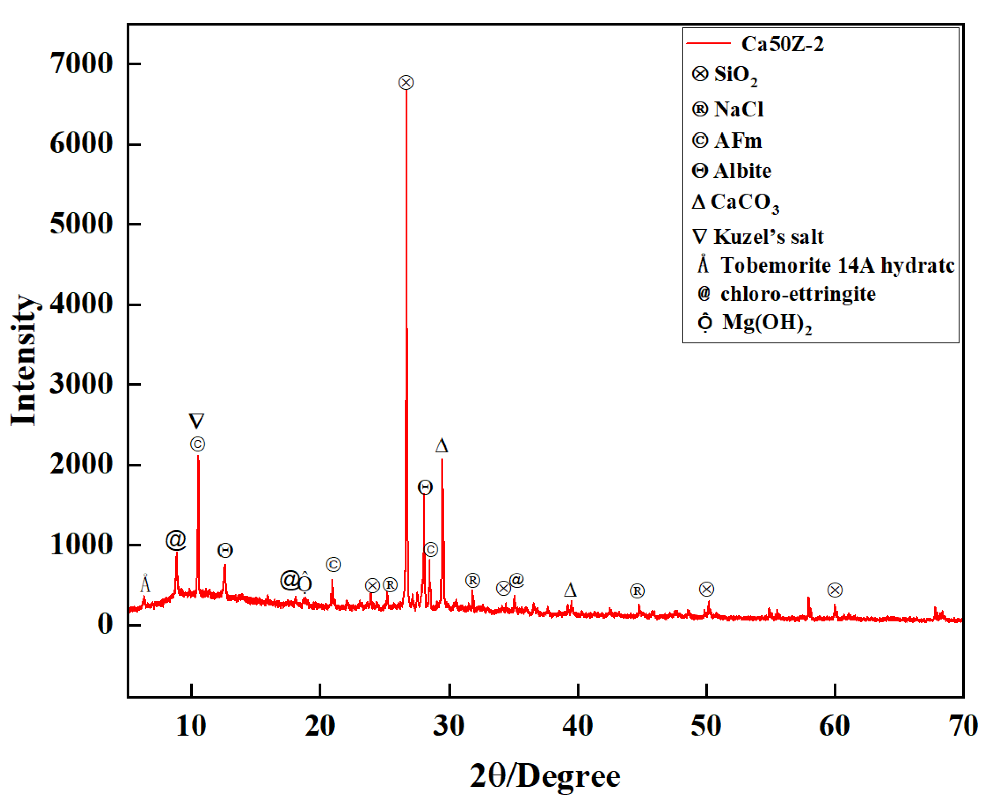
2.4.3. HPC Surface Corrosion Product XRD Test

The surface corrosion specimens of HPC were subjected to vacuum gold spraying treatment using the ETD-2000 miniature ion sputtering instrument produced by Beijing Boyuan Micro Nano Technology Co., Ltd. (Beijing, China) to terminate the corrosion reaction. The technical parameters of the vacuum gold spraying treatment were as follows: a gold spraying current of 10 mA, an air pressure of 0.2 mbar (20 Pa), and a gold spraying thickness of 20 nm. After primary grinding, sieving, and secondary sieving, specimens meeting the fineness requirement of 200 mesh were selected. An X-ray diffractometer (D/max-2500PC, CuKα target, Rigaku Corporation, Tokyo, Japan) was employed to conduct XRD phase analysis of the corrosion products.

2.4.4. SEM-EDS Test of the HPC Microstructure

Using the method for preparing XRD samples, specimens mainly composed of cement slurry were prepared for SEM testing to observe the microstructure of the specimens. SEM testing was performed using the COXEM EM-30PLUS desktop scanning electron microscope (SEM) from Silicon Valley Daejeon City of the Republic of Korea, with parameters including a resolution of less than 5 nm, an acceleration voltage of 20 kV, and a current of 15 mA. The EDS-ACT X-ray energy dispersive spectrometer produced by Oxford Instruments in Oxford, UK, was used for micro-area elemental analysis to obtain EDS images.

3. Results and Analysis

3.1. Damage Phenomena of HPC after 10-Year of Immersion in Brine

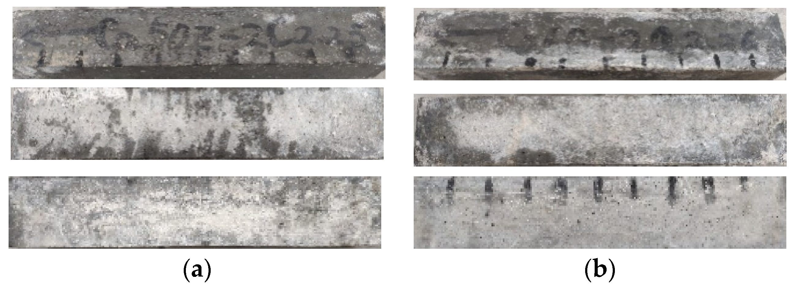
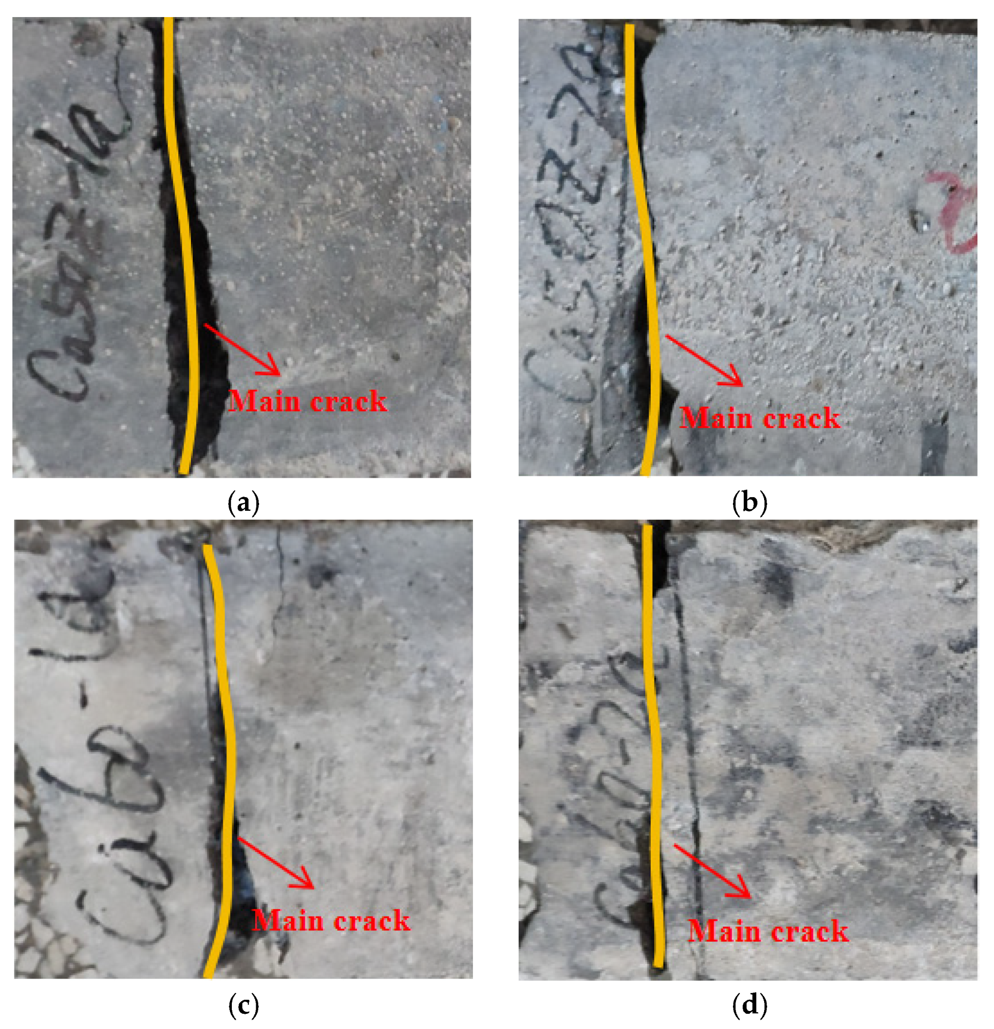
3.1.1. Macroscopic Damage Analysis

Figure 3a,b depict the surface corrosion observed on Ca50Z-2 and Ca60Z-2 specimens of HPC following a 10-year immersion in brine. The images depict the top, side, and bottom surfaces. As observed from Figure 3, the specimens remain intact without any signs of surface spalling, delamination, or cracking, indicating the absence of structural damage at the macroscopic level. This suggests that HPC maintains structural integrity even after long-term immersion in brine, demonstrating excellent corrosion resistance. Therefore, HPC can be widely promoted for use in the Qinghai area.

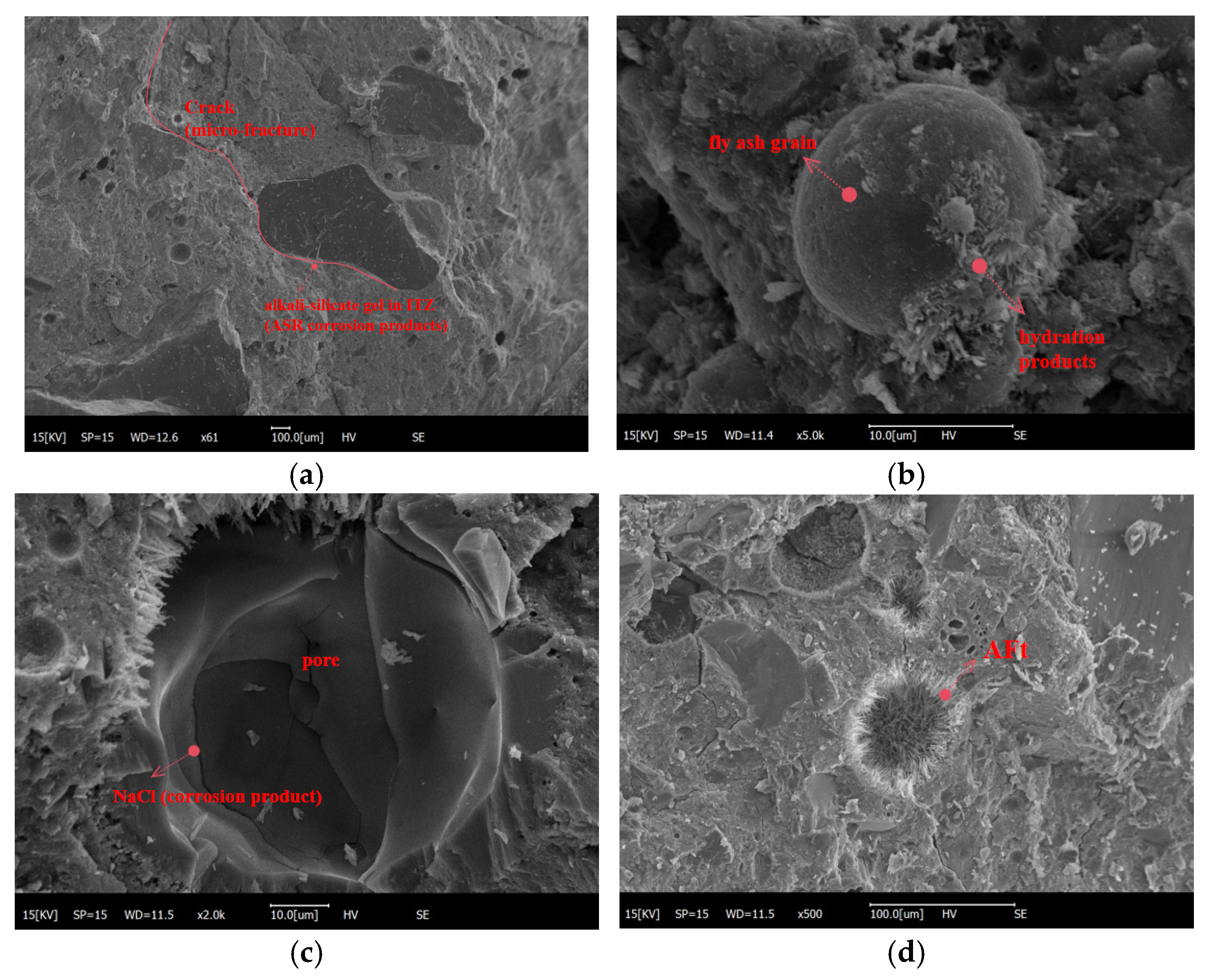
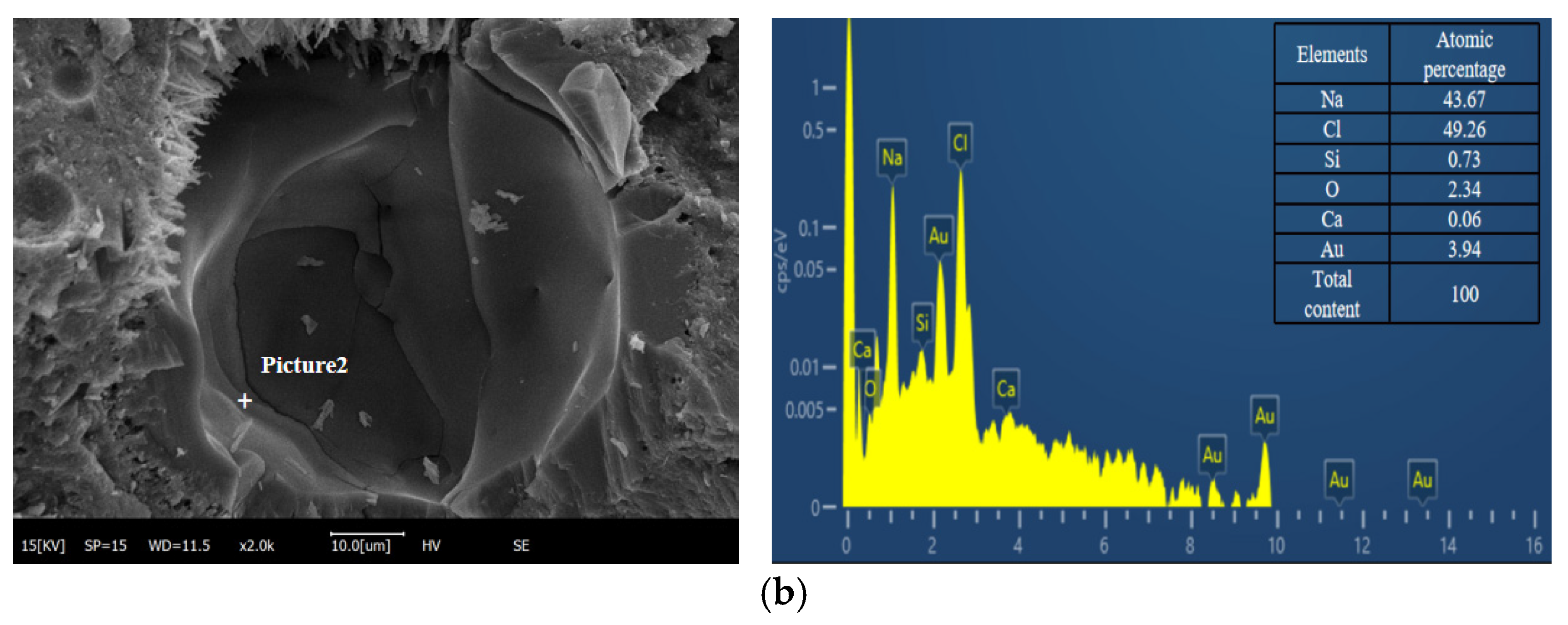
3.1.2. Microscopic Damage Analysis

From a macroscopic perspective, the brine corrosion does not cause severe damage to the surface of HPC. To investigate the corrosion damage of HPC, this paper conducted an XRD microscopic analysis of the mortar. Figure 4 shows the XRD spectrum of Ca50Z-2 immersed in salt lake brine for 3650 days, where quartz (SiO2) and albite (Na2O·Al2O3·6SiO2) are impurities from the raw materials in the concrete sample. As observed from the figure, the corrosion of sulfate and chloride salts in salt lake brine coexists and affects the hydration products of concrete and the secondary hydration reaction of mineral admixtures in concrete, as well as the crystalline growth of CSH gel. The corrosion products of brine include physical corrosion products such as NaCl, chemical corrosion products like ettringite (AFt, 3CaO·Al2O3·CaSO4·12H2O), Kuzel’s salt (3CaO·Al2O3·0.5CaCl2·0.5CaSO4·10H2O), Friedel’s salt (3CaO·Al2O3·CaCl2·10H2O), and magnesium hydroxide (Mg(OH)2). Meanwhile, a certain portion of AFt also originates from the secondary hydration products of mineral admixtures. Calcium carbonate (CaCO3) mainly belongs to the carbonation products of CH, and a small amount of tobermorite (14 Å) is the long-term crystallization growth morphology of CSH (Calcium Silicate Hydrate) gel. These corrosion products do not cause severe corrosion damage, such as surface cracking in HPC. To further investigate the internal corrosion damage of HPC, this paper conducted SEM-EDS analysis of the microstructure of mortar samples on the surface of concrete.
Figure 5 illustrates the SEM images of the mortar layer of HPC with the mix proportion of Ca50Z-2 after immersion in salt lake brine for 3650 days. From Figure 5a, it can be observed that the internal microstructure of the HPC is relatively intact, with minor cracks appearing in the mortar and extending along the pores, but these cracks are not significant. The reason for this phenomenon is that FA undergoes a pozzolanic reaction in the salt brine solution, forming flocculent products that encapsulate around the fly ash particles, as shown in Figure 5b. The incorporation of FA in HPC induces a secondary hydration reaction over time, resulting in a decrease in calcium hydroxide (CH) content within the cement hydration products. Consequently, this reduction in CH content diminishes the susceptibility of the concrete to sulfate corrosion initiated by brine exposure. Through the prolonged secondary hydration reaction of mineral admixtures in HPC, both the physical and chemical corrosion effects of brine are mitigated in Figure 5c.
Additionally, Figure 5d shows a large amount of needle-like and rod-like AFt crystals inside the air voids, which inevitably reduces the formation of AFt in the capillary pores inside the concrete, thereby mitigating the brine corrosion of the concrete. Figure 6 demonstrates a high content of Na+, indicating an ASR occurring around the FA, resulting in the formation of NCSH gel products (Figure 6a) and the corrosion product NaCl (Figure 6b). Meanwhile, the pores absorb the NCSH gel products, indicating that FA can effectively adsorb Na+ and reduce the concentration of Na+ around the alkali-reactive aggregate, thereby alleviating the formation and expansion of cracks caused by ASR gel expansion in the transition zone of alkali-reactive aggregate particles. This fully demonstrates that HPC designed with specific mix proportions still exhibits excellent corrosion resistance under long-term exposure to salt lake brine corrosion.
Although a large amount of mineral admixtures significantly inhibit the ASR hazard of alkali-reactive aggregates in concrete, there still exist uneven ASR gel products and their induced discontinuous micro-fine interface cracks around some alkali-reactive aggregate particles in localized areas. The expansion process of these micro-cracks is as follows: firstly, micro-cracks form in the cement paste, and then these cracks propagate through connected pores. Secondly, micro-cracks extend to form mortar cracks at the interface between cement paste and aggregate due to the ASR, as shown in Figure 5a. Finally, mortar cracks propagate further by connecting pores, with one path extending along the coarse aggregate interface to form interface cracks and another path penetrating through the coarse aggregate to form mortar cracks. These mortar cracks and interface weak points serve as the sources of crack propagation in concrete under stress. As the load increases, mortar cracks and coarse aggregate interface cracks gradually connect and expand to form a three-dimensional network of cracks, leading to the failure and disintegration of the concrete structure.

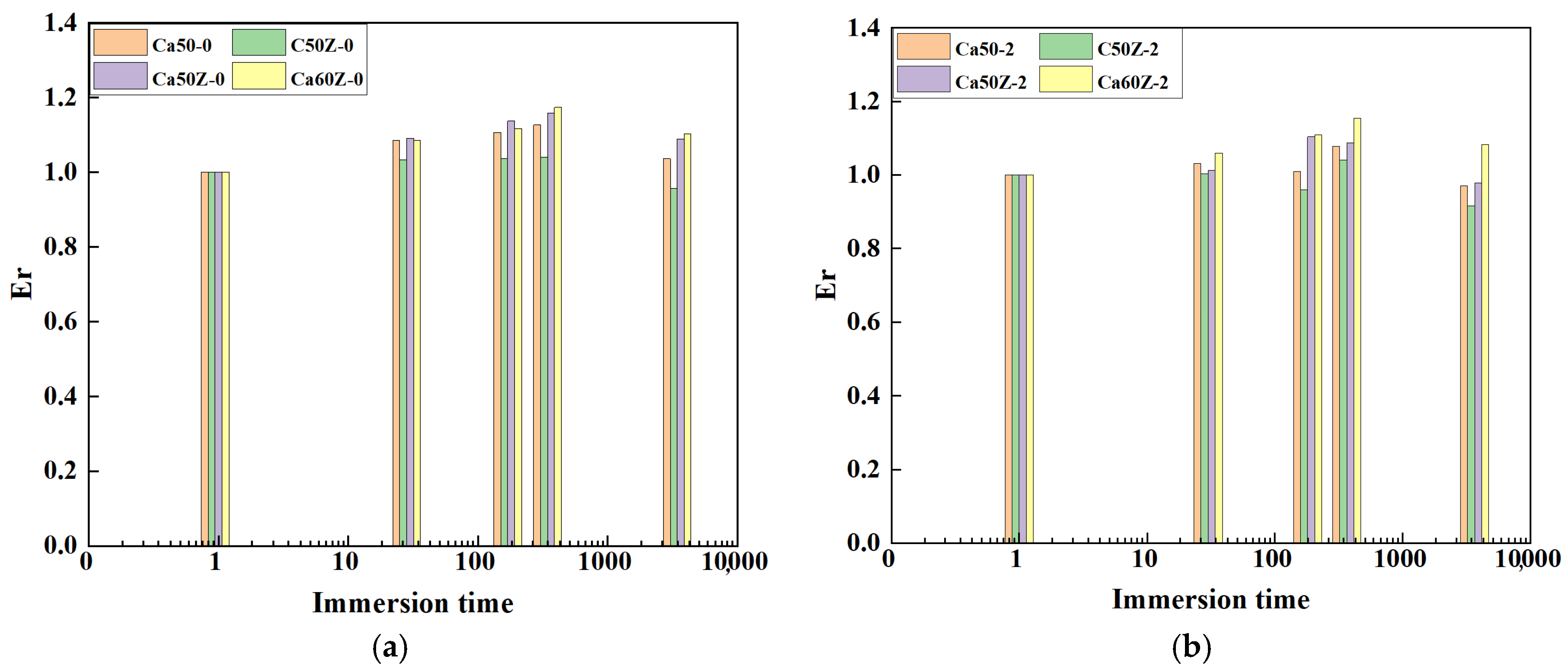
3.2. Relative Dynamic Modulus and Corrosion Damage Issues

Er was calculated based on the concrete dynamic modulus E measured using the ultrasonic pulse velocity test method, according to Equation (2). Table 5 summarizes the Er of Ca50, C50Z, Ca50Z, and Ca60Z in low alkali content (-0) and high alkali content (-2). The Er values for most specimens exhibit an overall “first increase, then decrease” trend with the immersion period, as depicted in the bar chart in Figure 7a,b. However, the variation trend of Er for Ca50-2 and C50Z-2 differs, showing a “slow decrease followed by an increase and then decrease again” trend. Nevertheless, all Er values fall within the range of 91% to 118%, exceeding 90%, indicating minimal corrosion damage. During the immersion period of 0 to 365 days, Er gradually increases by 4.01~17.36% with the prolongation of immersion time, peaking at 365 days. This might be attributed to the intrusion of corrosion ions from the brine, resulting in the continuous crystallization of corrosion products such as AFt and gypsum, which fill the internal pores of HPC, thereby strengthening the mechanical properties and subsequently increasing Er. However, after immersion for 3650 days, due to the coupling effect of brine corrosion and the ASR, the accumulation of corrosion products increases, causing slight expansion and the formation of micro-cracks within HPC, resulting in damage and a decrease in mechanical properties. Eventually, this leads to a decrease in Er, consistent with the microscopic observations.
It is commonly understood that Er serves as a parameter indicative of internal damage within concrete. When Er is smaller than 100%, it suggests that the corrosion product enhances the mechanical properties. Referring to Table 5, it becomes apparent that after 3650 days of exposure to brine, the Er value for C50Z-2 is 91.53%, while for other specimens, it remains greater than that of C50Z-2 or close to 100%. This observation implies that corrosion products have less effect on the mechanical properties of concrete. This finding aligns with the microscopic damage analysis conclusion, demonstrating the robust long-term corrosion resistance of HPC in salt lake brine environments. Consequently, HPC can be well applied to the salt lake brine environment.

3.3. Splitting Tensile Mechanical Properties

3.3.1. Variation Law of Splitting Tensile Strength with Immersion Time

Through the test, the splitting tensile strength values of HPC immersed in brine for 0 days, 28 days, 180 days, 365 days, and 3650 days were measured, as shown in Table 6. Due to the extended test duration and non-equidistant spacing, the time axis (X-axis) is expressed in logarithmic coordinates. The Origin 2024 software was utilized to depict the variation in splitting tensile strength with immersion time, as shown in Figure 8. Figure 8a,b illustrates the splitting tensile strength values of 8 specimens in low alkali state (-0) and high alkali state (-2) of Ca50, C50Z, Ca50Z, and Ca60Z strength grades. It is evident that the splitting tensile strength initially increases and then decreases over time. Specifically, during the initial stage of immersion, the splitting tensile strength shows an upward trend with prolonged immersion time. Most specimens exhibit peak splitting tensile strength after 360 days of immersion, except for Ca50Z-2, which does not demonstrate peak strength at this point. Subsequently, with continued immersion, the splitting tensile strength gradually decreases, reaching a low point at 3650 days. This phenomenon may be attributed to the initial hydration of HPC in salt lake brine, leading to the formation of a small amount of corrosion products. As the immersion time prolongs, corrosion products accumulate steadily, progressively occupying the pores within the concrete. This process fortifies the structure of HPC, thereby augmenting its mechanical properties and, consequently, enhancing its splitting tensile strength. However, as the volume of corrosion products increases, the expansion may lead to damage within the HPC structure, manifesting in the formation of fine cracks. Ultimately, the splitting tensile strength of HPC diminishes yet remains higher than its initial value. This observation aligns with the microscopic findings outlined in Section 3.1.2 of this paper.
Overall, the variation in splitting tensile strength with immersion time is similar to that of the relative dynamic elastic modulus. Upon immersion of HPC in salt lake brine from 0 d to 365 days, the relative dynamic elastic modulus exhibits a gradual increase, indicative of corrosion products progressively filling internal pores, thereby strengthening the mechanical properties of HPC and resulting in a gradual rise in splitting tensile strength. However, after 3650 days of immersion time, the gradual accumulation and expansion of corrosion products leads to a decline in the relative dynamic elastic modulus. Consequently, damage occurs inside HPC, and the corrosion products compromise its mechanical properties, culminating in a gradual decrease in splitting tensile strength.
Taking Ca50Z-0, Ca50Z-2, Ca60Z-0, and Ca60Z-2 as examples, Figure 9a–d depicts the failure mode of HPC in the test. There is no significant difference in the failure mode among specimens with varying strength grades and proportions; all exhibit splitting failure. Under the applied load, stress concentration occurs near the strip of the specimen, leading to the emergence of fine cracks and partial surface peeling. As the loading test progresses, damage accumulates gradually, main cracks proliferate, and their width expands. Eventually, primary cracks form on the surface and traverse through the specimen, showcasing a typical splitting failure pattern.

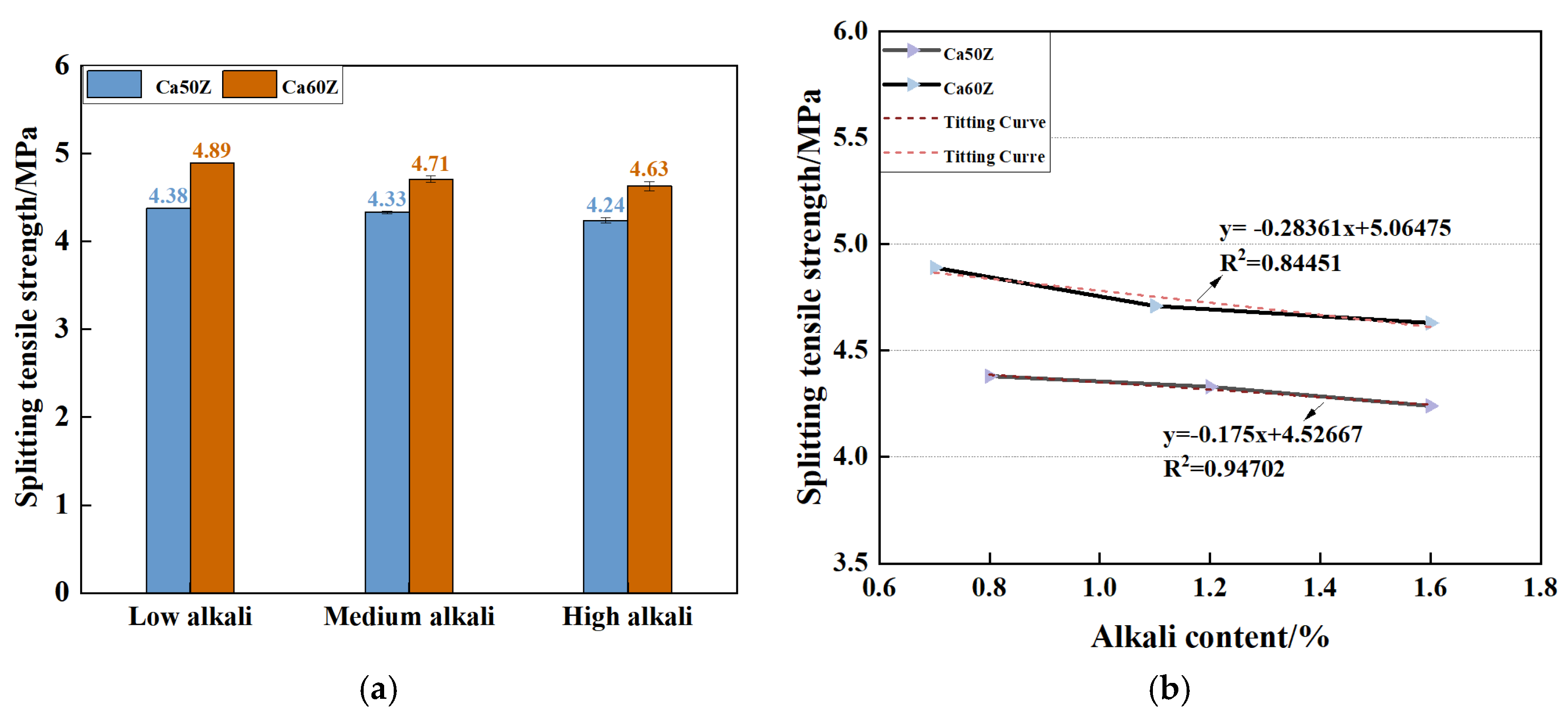
3.3.2. Variation in Splitting Tensile Strength with Alkali Content and Admixture

Using Ca50Z and Ca60Z as representatives, the impact of alkali content on splitting tensile strength is illustrated in Figure 10. Figure 10a shows that the splitting tensile strength of HPC subjected to brine immersion for 3650 days diminishes with escalating equivalent alkali content, maintaining identical strength grades and admixtures. The splitting tensile strength values for Ca50Z-0, Ca50Z-1, and Ca50Z-2 are 4.38 MPa, 4.33 MPa, and 4.24 MPa, respectively. Observations reveal that the splitting tensile strengths of the medium alkali state (-1) and high alkali state (-2) arerespectively, 1.14% and 3.19% lower than that of the low alkali state (-0). For Ca60Z, employing a similar analytical approach, it is determined that the medium alkali state (-1) and high alkali state (-2) exhibit reductions in splitting tensile strength by 3.68% and 5.32%, respectively, compared to the low alkali state (-0). Notably, under identical conditions, the decrease in splitting tensile strength is more pronounced in the high alkali state compared to the medium alkali state, indicating heightened sensitivity to high alkali states. Furthermore, the relatively low decline rate in splitting tensile strength suggests the absence of significant corrosion in HPC. The improvement shows that the proportion mixed with mineral admixtures to inhibit the ASR has a good effect on reducing brine corrosion and ASR double corrosion.
In order to delve deeper into the correlation between alkali content and the splitting tensile strength of HPC, a regression analysis was conducted on the splitting tensile strength alkali content relationship (Figure 10b). It can be found that there exists a pronounced linear relationship between the two variables. Examining Figure 8a reveals that after immersion in brine for 3650 days, the splitting tensile strength of Ca50-0, C50Z-0, and Ca50Z-0 is measured at 4.58 MPa, 4.15 MPa, and 4.38 MPa, respectively. This dataset shows that under identical strength grades and alkali content, the splitting tensile strength follows a distinct trend: highest for single-doped air-entraining agent, followed by double-doped air-entraining agent and rust inhibitor, with the single-doped rust inhibitor yielding the lowest strength. This discrepancy can potentially be attributed to the introduction of air-entraining agents, which serve to maintain the requisite air content within the HPC. These pores accommodate a certain amount of corrosion products, thereby mitigating the expansion associated with such products and subsequently enhancing the mechanical properties of the HPC.

3.3.3. Splitting Tensile Strength and Relative Dynamic Elastic Modulus

Er serves as a parameter for characterizing the internal damage of concrete, which reflects the concrete strength variation to a certain extent. Theoretically, a higher Er corresponds to greater splitting tensile strength, suggesting a positive correlation between them. To facilitate the analysis of splitting tensile strength variation with Er, the relationship between relative splitting tensile strength (fs-r) and Er was established through fitting analysis. Given the relatively discrete nature of the test data, discerning a clear functional relationship between the two variables proves challenging. Thus, to maximize the utility of the original data, a fitting analysis employing the method of averaging the boundary range was adopted. The analysis results reveal a linear relationship between the two parameters, as depicted in Figure 11.
From Figure 11, it is clear that the relationship between relative splitting tensile strength and Er differs between specimens of strength grades C50 and C60. Specifically, for C50 specimens, the black fitting curve illustrates this relationship, while for C60 specimens, the red fitting curve delineates the relationship. For specimens with a strength grade of C50 and a sample size (n) of 20, resulting in 18 degrees of freedom (n − 2), the critical correlation coefficient is determined to be 0.482. Notably, at a significance level of 0.05, 0.482 is less than 0.8379, indicating a significant linear relationship between fst-r and Er. Similarly, for specimens with a strength grade of C60 and a sample size (n) of 10 with 8 degrees of freedom, the critical correlation coefficient is 0.632. Again, at a significance level of 0.05, 0.632 is less than 0.8718. From this, it can be seen that there is a significant linear relationship between fst-r and Er, as shown in Equations (4) and (5). Based on the aforementioned correlation as well as the relationship between fst-r and the initial splitting tensile strength (fst-0), Equations (4) and (5) are multiplied by fst-0 of HPC from Table 6 in immersion 0 day, which leads to the derivation of the functional relationship between fst and Er. These findings distinctly illustrate that the variation in Er of HPC can better reflect the change in splitting tensile strength.
f s t r = 1.636 E r 0.606   C 50   R 2 = 0.702
f s t r = 1.574 E r 0.576   C 60   R 2 = 0.760
Er (Section 2.4.1 test method) can be calculated by measuring the propagation velocity V of an ultrasonic wave in concrete by measuring the ultrasonic wave of concrete. Subsequently, the splitting tensile strength of concrete can be determined utilizing the aforementioned relationship (Equations (4) and (5)). This study serves as a theoretical reference for obtaining the macroscopic mechanical parameters of concrete through non-destructive tests in the future.

4. Mesoscopic Mechanism Analysis of Splitting Tensile Failure of Concrete

Scholars have shown considerable interest in understanding the damage and failure mechanisms of concrete, employing various analytical approaches such as the finite element method (FEM) and discrete element method (DEM). At the mesoscopic scale, concrete is often conceptualized as a three-phase system comprising aggregates, mortar, and the interface transition zone (ITZ). However, existing models derived from these methods often struggle to accurately capture the thickness of the ITZ. Hence, leveraging fracture mechanics theory and integrating the strengths of the FEM and the DEM, a novel 3D mesoscopic model based on FDEM [26,27,28] is proposed. This model aims to simulate the elastic-plastic deformation and continuous mechanical behavior of concrete, particularly emphasizing the criticality of the ITZ thickness by considering bonding elements as having zero thickness.

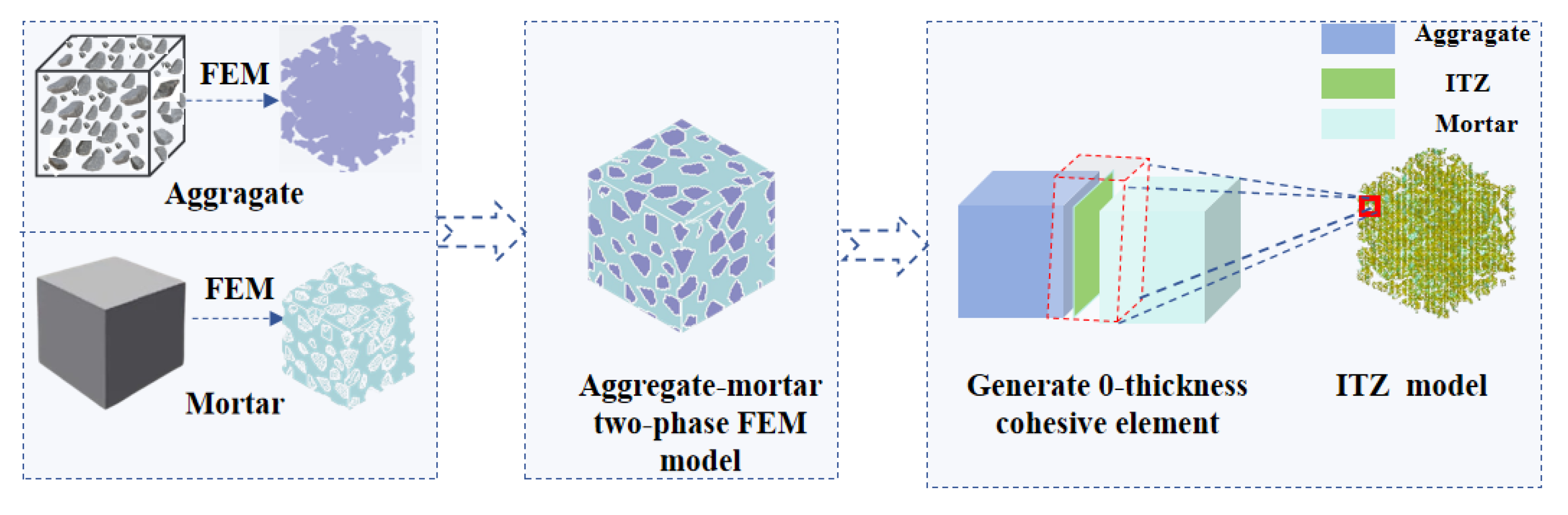
4.1. The Establishment of the 3D Mesoscopic Model Based on FDEM

It is widely acknowledged that the mechanical properties of each component within the mesoscopic structure of concrete exhibit randomness. Consequently, concrete represents a complex system characterized by stochastic parameters. Therefore, adopting a 3D finite element mesoscopic model with random aggregates is deemed more objective for simulating mechanical behavior. The specific modeling procedure entails [29,30]: 1. Establishment of a 3D random aggregate model devoid of concave corners and flake features. Employ the random aggregate algorithm to generate a spatially random octahedral aggregate matrix. Subsequently, grow polyhedral aggregates on the octahedral matrix, iterating this process N times to produce a random N-faceted polyhedron. Employing the convexity judgment rule for polyhedra, determine circularly that the polyhedron is convex. Repeat the growth of convex polyhedra N times in space to form a 3D random polyhedron assembly, generating various particle sizes according to the Fuller gradation of the aggregates. 2. Random placement of aggregates. Utilize the “Take and Place” algorithm [31] along with random placement of aggregates following the Fuller grading curve to ensure the randomness of aggregate distribution. 3. Finite element division and attribute identification. Employing the mapping grid method, the grid is initially discretized, followed by projecting the discrete grid onto the area of the random aggregate model using the grid projection algorithm. Subsequently, based on the material properties of different elements, the mortar element, aggregate element, and ITZ element are sequentially determined. 4. Generation of cohesion units. Firstly, the aggregate and mortar common node coordinate data are extracted. Then, utilizing the intersection algorithm, the contact surfaces are identified, and contact surface node separations are computed, resulting in the generation of cohesion units. The 3D mesoscopic model based on FDEM is subsequently constructed using contact interaction and a constitutive model allocation algorithm, as illustrated in Figure 12.

4.2. Material Model and Parameter Determination

4.2.1. K and C Model, HJC Model, and Cohesive-General Material Model

Concrete compression entails both vertical compression and horizontal expansion, accompanied by complex stresses like tension, shear, and compression. Given the multifaceted loading conditions and stress variations, this study applies the K and C material model, specifically the *MAT_CONCRETE_DAMAGE_REL3 model in LS-DYNA software (V4.3.8) [32]. This model encompasses an initial yield surface, an ultimate strength surface, and a residual strength surface, facilitating the simulation of transitions between these surfaces and the softening behavior between the ultimate strength and residual strength surfaces. Additionally, to capture the large deformations of concrete under quasi-static or dynamic impact conditions, the new Johnson Holmquist Cook (HJC) model [33], proposed by T.J. Holmquist and G.R. Johnson, is employed. The HJC model, renowned for its incorporation of strain rate, hydrostatic pressure, and damage accumulation effects on strength, is widely applied in numerical simulations. Its comprehensive constitutive model comprises three sub-models: the strength model, the damage model, and the state equation. To ensure that the zero-thickness cohesive element simulation accurately reflects mechanical behavior during fracture processes, the Cohesive_General material model in LS-DYNA is utilized to characterize the mechanical behavior of the ITZ.

4.2.2. Determination of Material Model Parameters

The K and C material model, HJC model, and Cohesive_General material model in LS-DYNA software require the determination of parameters such as density (ρ), compressive strength (fc), and splitting tensile strength (fst) for mortar, aggregate, and the ITZ. Experimental measurements provide the macroscopic mechanical parameters of mortar and aggregate. Utilizing the calculation formula proposed by Wang et al. [34], the model parameters of the ITZ are derived. The summarized parameters for the three material models are presented in Table 7.

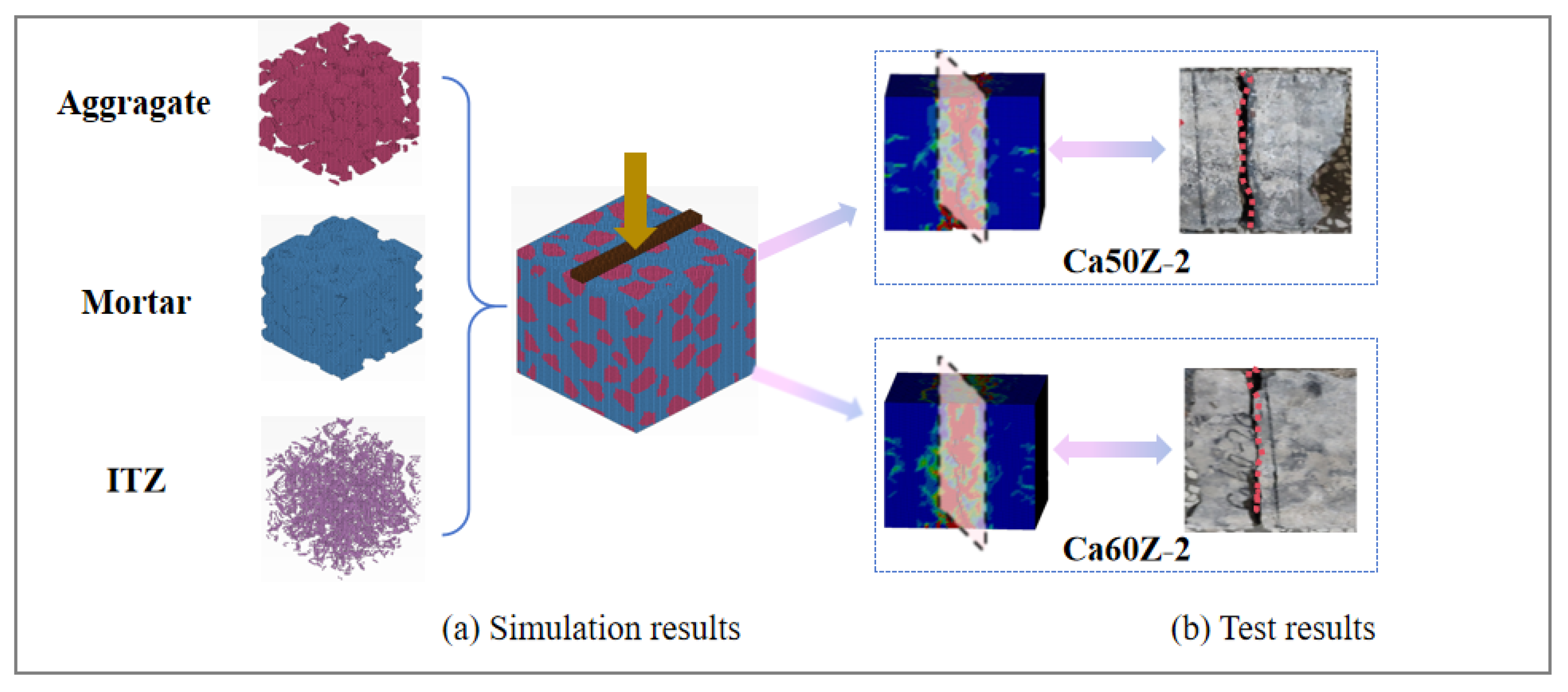
4.3. The Verification of Simulation

To verify the reliability of the material model and parameters, LS-DYNA was employed to simulate the splitting tensile mechanical properties of specimens Ca50Z-2 and Ca60Z-2. Following the modeling approach outlined above, cubic concrete specimen models measuring 100 mm × 100 mm × 100 mm were established. The aggregate size ranged from 5 mm to 20 mm, with aggregate volume ratios of 26.7% for Ca50Z-2 and 34.7% for Ca60Z-2. The total number of cells was 125,000 and 250,047, respectively. Simulation parameters were determined based on the results presented in Table 7, with a vertical displacement load applied to the strips at a loading speed of 2.7 × 10⁻⁶ m/s. To maintain consistency with the experimental setup, fixed constraints were imposed on the upper and lower strips, and a strip width of 10 mm was applied.
Figure 13 illustrates the mesoscopic failure morphology of splitting tensile strength for Ca50Z-2 and Ca60Z-2 cube specimens. In Figure 13a, stress concentration is observed at the point of contact between the upper strips and the specimen, with stress propagating downward along the specimen’s center, resulting in cracking of the upper part. Similarly, stress in the lower part propagates upward along the center, leading to cracking until the upper and lower cracks converge, forming a main crack (red dotted line in Figure 13b) at the specimen’s midpoint and culminating in tensile failure. Under horizontal tensile load, the specimen splits into two halves, forming a flat fracture surface. Notably, the splitting failure pattern depicted in the numerical simulation aligns with the test results shown in Figure 13b.
Table 8 shows the comparison between the splitting tensile strength of the numerical simulation and that of the test. The findings indicate that, for specimens Ca50Z-0, Ca50Z-2, Ca60Z-0, and Ca60Z-2, the error range of peak stress falls within −0.91% to +2.25%, indicating small discrepancies. The observed error may stem from systematic or random errors during testing, as well as calculation inaccuracies in the model. In summary, the material model described above effectively captures the stress variations and splitting tensile mechanical behavior of HPC cube specimens in the splitting tensile test. This suggests the accuracy of the simulation method and the reasonableness of the simulation parameters.

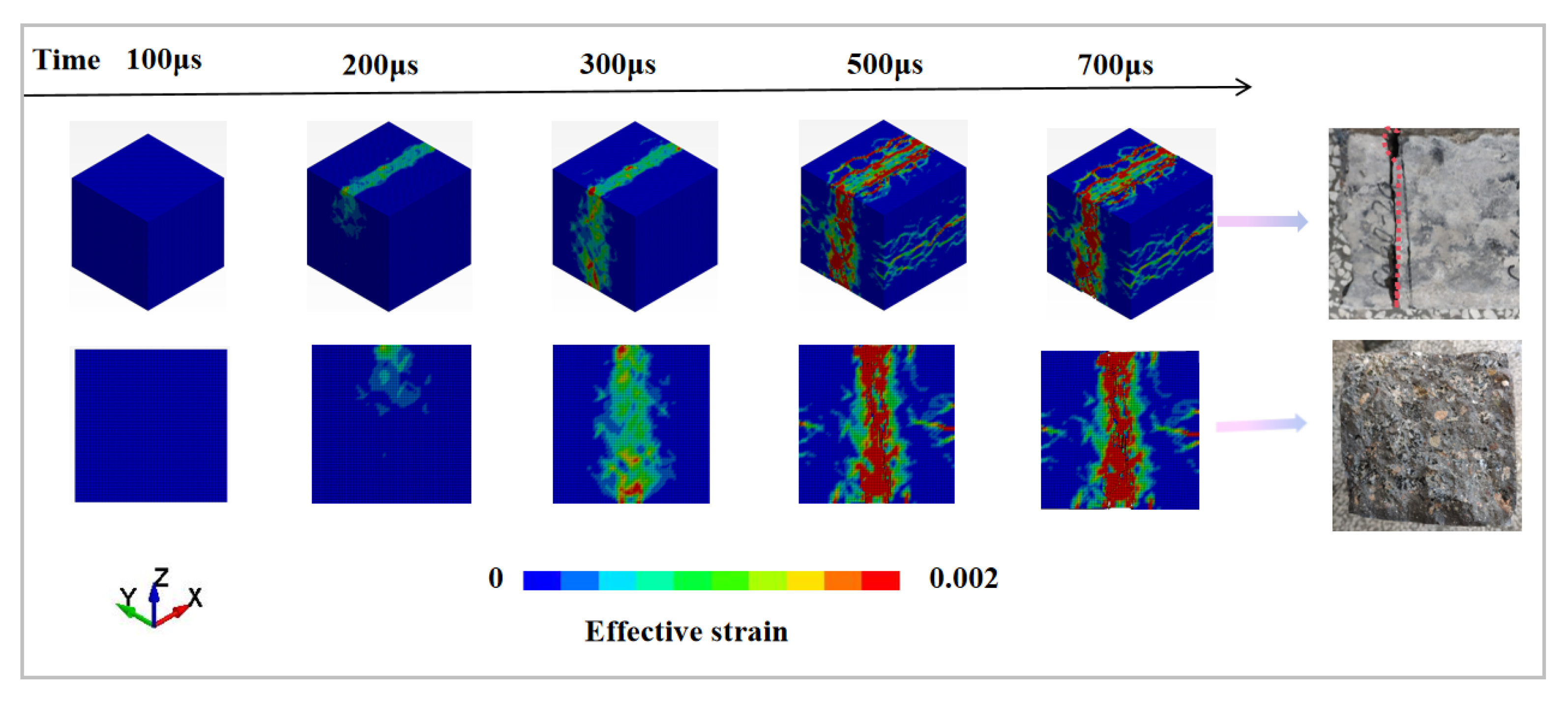
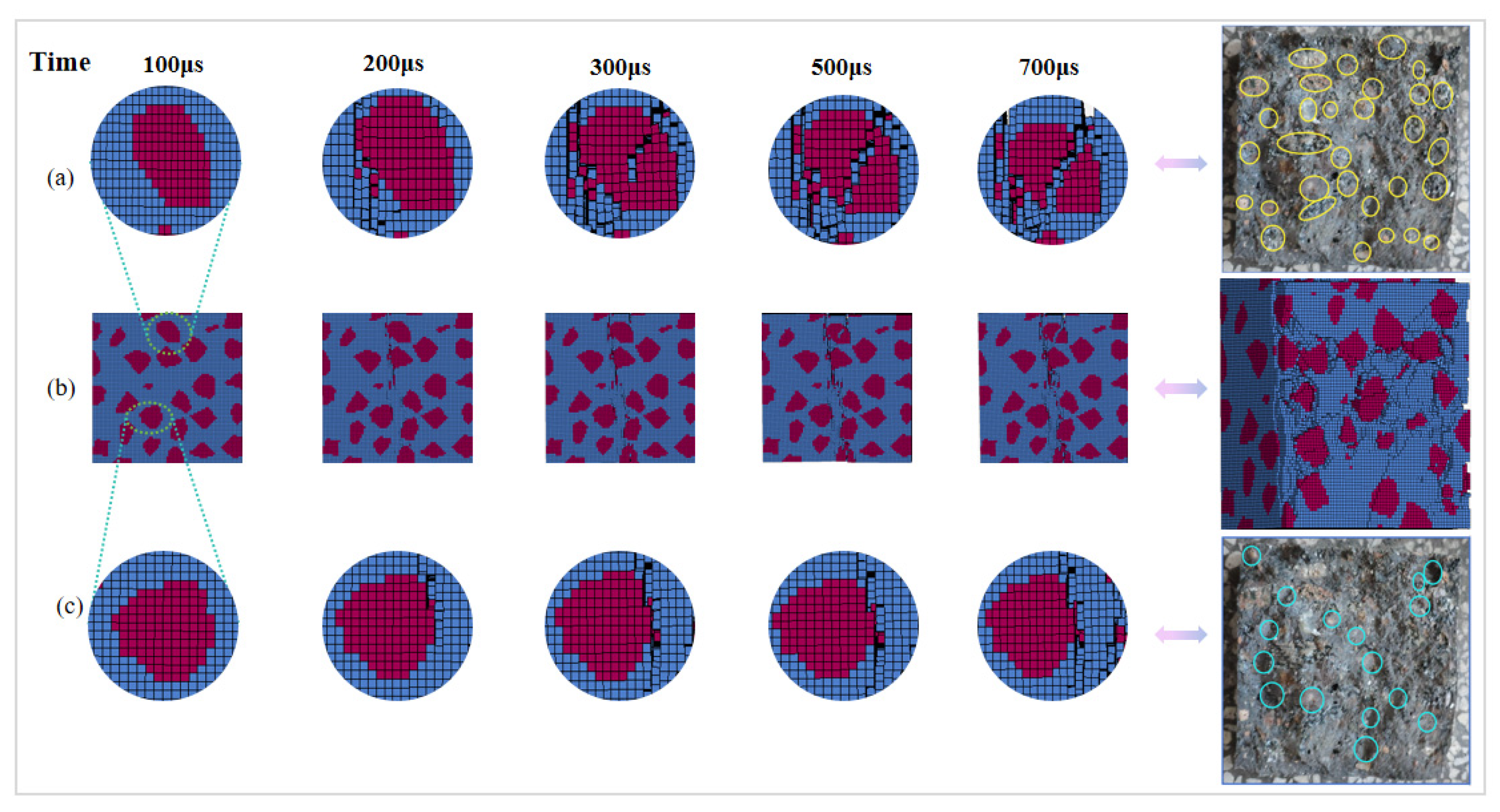
4.4. The Meso-Mechanical Failure Process and Mechanism of Splitting Tensile

To delve deeper into the failure mechanism of HPC under static splitting tensile loads, a detailed analysis of the meso-failure process of HPC is conducted based on fracture mechanics theory, as depicted in Figure 14 and Figure 15. The analysis reveals that HPC undergoes splitting tensile damage when subjected to vertical downward loading. Initially, the mortar at the contact position between the strip and the specimen is compromised, leading to the generation of mortar cracks. With continued loading, the damage exacerbates progressively. Mortar cracks continue to propagate along the stress direction, expanding from both the top and bottom towards the center of the specimen. During the crack propagation process, two distinct characteristics are observed: firstly, mortar cracks propagate around the aggregate through the interface (Figure 16c). This phenomenon is attributed to the influence of ASR corrosion on the interface, resulting in diminished interfacial bonding strength between the aggregate and mortar. Consequently, the crack propagates along the weakened interface area. Secondly, mortar cracks propagate through the aggregate (Figure 16a), indicating robust interface bonding strength between the aggregate and mortar. In such cases, the crack necessitates higher surface energy to traverse the interface. Consequently, the crack bypasses the interface and traverses through the aggregate, ultimately forming a crack through the entire specimen. Therefore, the specimen loses its load-bearing capacity, leading to the failure and disintegration of the concrete structure.
To compare the splitting tensile mechanical properties of CaZ50-2 and Ca60Z-2 cube specimens, an analysis of the aggregate failure ratio was conducted. The specimens were split along the fracture surface, as depicted in Figure 16b and Figure 17b. The number of broken aggregates (represented by yellow circles) on the fracture surface (Figure 16a and Figure 17a) and the number of aggregates bypassed by cracks through the interface (represented by blue circles) (Figure 16c) were recorded. For CaZ50-2, there were 31 yellow circles and 17 green circles. The percentage of broken aggregates was calculated, resulting in 64.58% for Ca50Z-2. Similarly, for Ca60Z-2, the percentage of broken aggregates was 90.3%. It was observed that the percentage of fractured aggregates in Ca60Z-2 was higher than that in Ca50Z-2. This finding aligns with the splitting tensile test results, which indicated that the splitting tensile strength of Ca60Z-2 was higher than that of Ca50Z-2. These results further underscore the reliability of the 3D mesoscopic model in simulating the splitting tensile mechanical behavior of HPC cubes.

5. Conclusions

(1)
The macroscopic observation indicates that brine corrosion does not cause significant damage to the surface of HPC. The internal damage of HPC was studied by XRD and SEM-EDS analysis of Ca50Z-2 specimens immersed in salt water for 10 years. The results showed that XRD reveals corrosion products from salt lake brine and ASR corrosion products, primarily including AFt, Kuzel’s salt, Friedel’s salt, and CSH gel. Although these corrosion products do not cause serious damage to HPC, micro-cracks are generated due to the expansion of these products. SEM-EDS microstructure images show the propagation path of micro-cracks and the formation process of mortar cracks.
(2)
The variation in relative dynamic elastic modulus with HPC immersion time was studied. The results show that the relative dynamic elastic modulus “increases first and then decreases” with the extension of immersion time. Specifically, during the period of 0~365 days, the relative dynamic elastic modulus gradually increases by 4.01~17.36% with immersion time. From 365 days to 3650 days, the expansion of corrosion products leads to the structural damage of HPC and the formation of micro-cracks, thus reducing the relative dynamic elastic modulus, which is consistent with the results of microscopic analysis.
(3)
The splitting tensile strength of HPC was analyzed. The conclusion is that under the action of 10 years of salt lake brine corrosion, the splitting tensile strength of HPC with ASR inhibition measures exhibited a trend of initially increasing and then decreasing, which is consistent with the rule of Er with immersion time. The influence of alkali content on splitting tensile strength revealed a decrease as alkali content increased. A relationship between splitting tensile strength and Er was derived through fitting analysis. This relationship also reflects the relationship between macroscopic mechanical properties and corrosion damage of HPC, which serves as a theoretical reference for obtaining the macroscopic mechanical parameters of concrete through non-destructive tests in the future.
(4)
The utilization of the 3D random aggregate mesoscopic model enables the simulation of splitting tensile mechanical properties and facilitates the analysis of internal crack propagation characteristics and failure mechanisms. Microscopic structural analysis and numerical simulation elucidate that there are still uneven ASR gel products and discontinuous fine interface cracks induced in the local area of HPC with ASR inhibition measures, which become the origin of splitting tensile failure cracks. Overall, during the splitting tensile process of concrete, mortar cracks exhibit two expansion paths. For Ca60Z-2, the proportion of coarse aggregates directly penetrated by mortar cracks is 90.3%, while the proportion of interface failures of mortar cracks bypassing coarse aggregates is only 9.7%. The data indicate that the number of coarse aggregates directly through the mortar crack is higher than the number of interface damage that occurs when the mortar crack bypasses the coarse aggregate.
The study may be limited by the fact that the HPC was immersed in salt lake brine for only 10 years, thus failing to capture the changes in its split tensile strength over its entire service life. In the future, it may be possible to extend the immersion time of HPC in salt lake brine to 20, 30, or even more years, thereby obtaining a better understanding of how its split tensile strength evolves over longer durations and predicting its lifespan in such environments. Additionally, optimizing numerical simulation methods and developing more models to simulate other mechanical properties of HPC could further enhance our understanding.

Author Contributions

F.W.: Resources, Investigation, Data Curation, Writing—Original Draft, Visualization; H.Y.: Conceptualization, Methodology, Writing—Review and Editing, Project Administration; H.M.: Funding Acquisition, Supervision; M.C.: Data Curation, Investigation; J.G. (Jianbo Guo): Investigation; J.Z.: Investigation; W.L.: Investigation; W.G.: Investigation; Q.T.: Investigation; J.G. (Juan Guo): Investigation. All authors have read and agreed to the published version of the manuscript.

Funding

This research was funded by the National Basic Research Program of China (973 Program) funded Project 2015CB655102 and the Qinghai Provincial Science and Technology Support Plan (2013-G-Q006A).

Data Availability Statement

The original contributions presented in the study are included in the article, further inquiries can be directed to the corresponding authors.

Conflicts of Interest

The authors declare no conflict of interest.

References

  1. Tan, B.; Okoronkwo, M.U.; Kumar, A.; Ma, H. Durability of calcium sulfoaluminate cement concrete. J. Zhejiang Univ. Sci. A Appl. Phys. Eng. 2020, 21, 118–128. [Google Scholar] [CrossRef]
  2. Taffese, Z.W.; Sistonen, E. Machine learning for durability and service-life assessment of reinforced concrete structures: Recent advances and future directions. Autom. Constr. 2017, 77, 1–14. [Google Scholar] [CrossRef]
  3. Hossain, M.M.; Karim, M.R.; Hasan, M.; Hossain, M.K.; Zain, M.F.M. Durability of mortar and concrete made up of pozzolans as a partial replacement of cement: A review. Constr. Build. Mater. 2016, 116, 128–140. [Google Scholar] [CrossRef]
  4. Tan, Y.; Wang, S.; Xu, F.; Liu, W.; Chen, X.; Liang, Y. Application of COMSOL Multiphysics in Research of Concrete Durability-A Short Review. J. Chin. Ceram. Soc. 2017, 45, 697–707. [Google Scholar] [CrossRef]
  5. Liu, L. Brief lntroduction on the Study of Erosion and Prevention of Concrete in Salt Lake and Saline Soil Area of Chaerhan, Chaidamu. J. Build. Mater. 2001, 4, 395–400. [Google Scholar]
  6. Venyite, P.; Nemaleu, J.G.D.; Kaze, R.C.; Tchamba, A.B.; Kamseu, E.; Melo, U.C.; Leonelli, C. Alkali-silica reactions in granite-based aggregates: The role of biotite and pyrite. Constr. Build. Mater. 2022, 320, 126259. [Google Scholar] [CrossRef]
  7. Ghiasvand, E.; Mohammadi, H.; Rezaei, Z.; Ayyoubi, M.; Dehghani, S. Evaluation of the durability of concretes containing alkali-activated slag exposed to the alkali-silica reaction by measuring electrical resistivity. Constr. Build. Mater. 2023, 367, 130094. [Google Scholar] [CrossRef]
  8. Kadhim, R.A.; Al-Taie, R.S.; Al-Mahaidi, R. Experimental and finite element analysis of mechanical behavior of concrete damaged by alkali aggregate reaction (AAR) and repaired with CFRP layers. IOP Conf. Ser. Mater. Sci. Eng. 2021, 1067, 012054. [Google Scholar] [CrossRef]
  9. Al-Rousan, R.Z. Cyclic behavior of alkali-silica reaction-damaged reinforced concrete beam-column joints strengthened with FRP composites. Case Stud. Constr. Mater. 2022, 16, e00869. [Google Scholar] [CrossRef]
  10. Huang, H.; Yuan, Y.; Zhang, W.; Zhu, L. Property Assessment of High-Performance Concrete Containing Three Types of Fibers. Int. J. Concr. Struct. Mater. 2021, 15, 39. [Google Scholar] [CrossRef]
  11. Saha, A.K.; Khan, M.N.N.; Sarker, P.K. The ASR mechanism of reactive aggregates in concrete and its mitigation by fly ash: A critical review. Constr. Build. Mater. 2018, 171, 743–758. [Google Scholar] [CrossRef]
  12. Harbec, D.; Zidol, A.; Tagnit, H.A. Mechanical and durability properties of high performance glass fume concrete and mortars. Constr. Build. Mater. 2017, 134, 142–156. [Google Scholar] [CrossRef]
  13. Li, L.; Ma, H.; Yu, H.; Zhang, J.; Cheng, M.; Wu, Z.; Yan, J.; Zhang, L.; Fan, H.; Wang, F. Attack resistance mechanism, uniaxial compressive mechanical properties and meso-simulation of high-performance concrete exposed to brine in salt lake for 10 years. Constr. Build. Mater. 2023, 407, 133520. [Google Scholar] [CrossRef]
  14. Yu, J.; Hu, M.; Yang, D. Damage research of C50 and C60 concrete under salt solution and load. Concrete 2015, 11, 17–20. [Google Scholar]
  15. Zhang, M.; Chen, J.; Lv, Y.; Wang, D.; Ye, J. Study on the expansion of concrete under attack of sulfate and sulfate–chloride ions. Constr. Build. Mater. 2013, 39, 26–32. [Google Scholar] [CrossRef]
  16. Cefis, N.; Comi, C. Damage modelling in concrete subject to sulfate attack. Frat. Ed Integrità Strutt. 2014, 8, 222–229. [Google Scholar] [CrossRef]
  17. Zhang, D.; Zuo, X.; Li, X. Coupling transmission model of chloride ion and sulfate ion in concrete. J. Civ. Eng. Manag. 2019, 36, 190–196. [Google Scholar] [CrossRef]
  18. Zhou, X.; Lu, D.; Du, X.; Wang, G.; Meng, F. A 3D non-orthogonal plastic damage model for concrete. Comput. Methods Appl. Mech. Eng. 2020, 360, 112716. [Google Scholar] [CrossRef]
  19. Lu, D.; Meng, F.; Zhou, X.; Zhuo, Y.; Gao, Z.; Du, X. A Dynamic Elastoplastic Model of Concrete Based on a Modeling Method with Environmental Factors as Constitutive Variables. J. Eng. Mech. 2023, 149. [Google Scholar] [CrossRef]
  20. Li, J.; Xu, Y.; Tian, Z.; Ma, J.; Jing, P.; Song, Z. Study on leaching damage mechanism of calcium ions of reactive powder concrete (RPC) under ion corrosion. Constr. Build. Mater. 2020, 269, 121303. [Google Scholar] [CrossRef]
  21. Jonny, N.; Rasoul, N. A Direct Tensile Strength Testing Method for Concrete from Existing Structures. CivilEng 2023, 4, 333–344. [Google Scholar] [CrossRef]
  22. Gautam, B.P.; Panesar, D.K.; Sheikh, S.A.; Vecchio, F.J. Effect of coarse aggregate grading on the ASR expansion and damage of concrete. Cem. Concr. Res. 2017, 95, 75–83. [Google Scholar] [CrossRef]
  23. Mehta, P.K. Studies on chemical resistance of low water/cement ratio concretes. Cem. Concr. Res. 1985, 15, 969–9978. [Google Scholar] [CrossRef]
  24. Ababneh, A.N. The Coupled Effect of Moisture Diffusion, Chloride Penetration and Freezing-Thawing on Concrete Durability. Ph.D. Dissertation, University of Colorado, Denver, CO, USA, 2002. [Google Scholar]
  25. GB/T 50081-2019; Ministry of Housing and Urban-Rural Development of the People’s Republic of China. Standard for Test Methods of Concrete Physical and Mechanical Properties. China Construction Industry Press: Beijing, China, 2019.
  26. Fang, Q.; Zhang, J. 3D numerical modeling of projectile penetration into rock-rubbk overlays accounting for random distribution of rock-rubble. Int. J. Impact Eng. 2014, 63, 118–128. [Google Scholar] [CrossRef]
  27. Fang, Q.; Zhang, J.; Zhang, Y.; Wu, H.; Gong, Z. A 3D mesoscopic model for the closed-cell metallic foams subjected to static and dynamic loadings. Int. J. Impact Eng. 2015, 82, 103–112. [Google Scholar] [CrossRef]
  28. Qin, F.; Zhang, J.; Yi, H.; Zhang, Y. The investigation into three-dimensional mesoscale modelling of fully-graded concrete. Eng. Mech. 2013, 30, 14–21. (In Chinese) [Google Scholar]
  29. Feng, L.; Chen, X.; Zhang, J.; Chen, C. Experimental and mesoscopic investigation of self-compacting rubberized concrete under dynamic splitting tension. J. Build. Eng. 2022, 57, 104942. [Google Scholar] [CrossRef]
  30. Zhang, J.; Zhang, Y.; Fang, Q. Numerical simulation of shock wave propagation in dry sand based on a 3D mesoscopic model. Int. J. Impact Eng. 2018, 117, 102–112. [Google Scholar] [CrossRef]
  31. Wriggers, P.; Moftah, S.O. Mesoscale models for concrete: Homogenisation and damage behaviour. Finite Elem. Anal. Des. 2006, 42, 623–636. [Google Scholar] [CrossRef]
  32. Malvar, L.J.; Crawford, J.E.; Wesevich, J.W.; Simons, D. A plasticity concrete material model for DYNA3D. Int. J. Impact Eng. 1997, 19, 847–873. [Google Scholar] [CrossRef]
  33. Holmquist, T.J.; Johnson, G.R. A computational constitutive model for concrete subjected to large strains, high strain rates, and high pressures. ASME J. Appl. Mech. 2011, 78, 051003. [Google Scholar] [CrossRef]
  34. Wang, F.; Yu, H.; Ma, H.; Chen, M.; Guo, J.; Guo, J.; Liu, W.; Gao, W.; Tao, Q.; Li, L. Mechanical Performance of The ITZ and Mesoscopic Compression Failure Mechanism of HPC with ASR Inhibition Measures under Long-term Brine Attack. Case Stud. Constr. Mater. 2024, 6, e00959, Prepublish. [Google Scholar]
Figure 1. Grading curve of coarse aggregate.
Buildings 14 01673 g001
Figure 2. The principle diagram of the splitting tensile test of concrete.
Buildings 14 01673 g002
Figure 3. The surface corrosion observed on Ca50Z-2 and Ca60Z-2 specimens of HPC. (a) Ca50Z-2. (b) Ca60Z-2.
Buildings 14 01673 g003
Figure 4. XRD spectrum of Ca50Z-2 immersed in salt lake brine for 3650 days [13].
Buildings 14 01673 g004
Figure 5. SEM image of Ca50Z-2 immersed in salt lake brine for 3650 days. (a) HPC-Ca50Z-2 × 61. (b) HPC-Ca50Z-2 × 5000. (c) HPC-Ca50Z-2 × 2000. (d) HPC-Ca50Z-2 × 500. Note: The four names of (ad) mean the number of specimens and magnification, such as HPC-Ca50Z-2 × 61: HPC-Ca50Z-2 is the number of the specimen while “×60” is the magnification.
Buildings 14 01673 g005
Figure 6. EDS diagram of corrosion products for Ca50Z-2 immersed in salt lake brine for 3650 days. (a) EDS of sodium-hydrated alkali silica gel (NCSH). (b) EDS of corrosion products (NaCl) [13].
Buildings 14 01673 g006aBuildings 14 01673 g006b
Figure 7. Variation in Er with immersion time. (a) Er of a low alkali state. (b) Er of a high alkali state.
Buildings 14 01673 g007
Figure 8. Variation law of splitting tensile strength with immersion time. (a) The splitting tensile strength of a low alkali state. (b) The splitting tensile strength of a high alkali state.
Buildings 14 01673 g008
Figure 9. Fracture diagram of the splitting tensile test. (a) Ca50Z-0. (b) Ca50Z-2. (c) Ca60Z-0. (d) Ca60Z-2.
Buildings 14 01673 g009
Figure 10. Effect of alkali content on splitting tensile strength. (a) Test data. (b) Fitting data.
Buildings 14 01673 g010
Figure 11. Relationship between relative splitting tensile strength and Er.
Buildings 14 01673 g011
Figure 12. The establishment of the 3D mesoscopic model based on FDEM.
Buildings 14 01673 g012
Figure 13. The overall mesoscopic failure morphology of HPC cubic specimens.
Buildings 14 01673 g013
Figure 14. Mesoscopic failure process of Ca50Z-2 splitting tensile.
Buildings 14 01673 g014
Figure 15. Mesoscopic failure process of Ca60Z-2 splitting tensile.
Buildings 14 01673 g015
Figure 16. Mesoscopic failure process of coarse aggregate fracture and coarse aggregate interface cracking of Ca50Z-2 under splitting tensile load. (a) Cracks pass aggregates; (b) Front section of the model; (c) Cracks pass through the interface.
Buildings 14 01673 g016
Figure 17. Mesoscopic failure process of coarse aggregate fracture and coarse aggregate interface cracking of Ca60Z-2 under splitting tensile load. (a) Cracks pass aggregates; (b) Front section of the model.
Buildings 14 01673 g017
Table 1. Physical and mechanical properties of cement.
TypeStandard Consistency/%Initial Setting Time/minFinal Setting Time/minFineness
/%
Specific Surface Area/m2·kg−1Compressive Strength/MPaFlexural Strength/MPa
3 Days28 Days3 Days28 Days
Cement261452200.835021.849.05.67.8
Table 2. Alkali-active constituents of the main raw materials.
ConstituentsCementFAGGBFSSF
Na2O/%0.240.630.271.03
K2O/%0.591.350.402.00
(Na2O + 0.658 K2O)/%0.631.520.532.35
Note: According to the national standard, the alkali content of cement is calculated as 100% of the equivalent alkali content, while the alkali content of admixtures equals 15% of the equivalent alkali content for FA, 50% for GGBFS, and 50% for SF. The alkali content of additives is considered to be 100% of the equivalent alkali content.
Table 3. Mix proportion of concrete specimen.
No.Material/kg·m−3Na2Oeq
/%
W/Bfc/MPa
CementFAGGBFSSFFineCoarseaZWater
Reducer
Water28 Days
(in Normal Environment)
3650 Days
(in Brine
Environment)
Ca50-0325601001574111590.25-101500.80.3052.465.4
Ca50-1325601001574111590.25-101501.30.3054.058.6
Ca50-232560100157411159--101501.80.3053.258.9
C50Z-032560100157411159-33101270.80.2559.661.4
C50Z-132560100157411159-33101271.30.2551.062.4
C50Z-2325601001574111590.2533101271.80.2555.560.3
Ca50Z-0325601001574111590.2533101270.80.2560.670.1
Ca50Z-1325601001574111590.2533101271.20.2561.066.2
Ca50Z-2325601001574111590.26833101271.60.2552.465.4
Ca60Z-0322801181673911550.2683313.41270.70.2454.058.6
Ca60Z-1322801181673911550.2683313.41271.10.2453.258.9
Ca60Z-2322801181673911550.253313.41271.60.2459.661.4
Note: FA: fly ash; GGBFS: grade ground granulated blast furnace slag; SF: silica fume; W/B: water-binder ratio.
Table 4. Simulated corrosion medium chemical composition/g·L−1.
ConstituentsNaClNa2SO4MgSO4CaSO4Ca(HCO3)2K2SO4NaClNa2SO4
Quantity208.9843.15.481.210.250.09208.9843.1
Table 5. Summary table of Er of HPC in brine corrosion after 3650 days.
Immersion TimeEr
Ca50-0Ca50-2C50Z-0C50Z-2Ca50Z-0Ca50Z-2Ca60Z-0Ca60Z-2
01.00001.00001.00001.00001.00001.00001.00001.0000
281.08521.03191.03271.00281.09021.01331.08481.0596
1801.10571.01001.03560.96031.13681.10401.11621.1087
3651.12631.07791.03921.04011.15801.08711.17361.1550
36501.03620.97000.95610.91531.08900.97841.08201.0830
Table 6. Summary table of splitting tensile strength of HPC in brine corrosion after 3650 days.
Immersion TimeSplitting Tensile Strength/MPa
Ca50-0Ca50-2C50Z-0C50Z-2Ca50Z-0Ca50Z-2Ca60Z-0Ca60Z-2
03.723.833.774.23.623.924.264.29
284.53.973.934.34.533.985.024.52
1804.83.873.954.014.614.565.144.78
3654.924.173.964.384.634.315.485.06
36504.584.134.154.324.384.244.894.63
Table 7. Material model parameters.
AggregateMortarITZ
Ca50-0Ca60-0Ca50-0Ca60-0Ca50-0Ca60-0
ρ/g·cm−3268026802500255025002550
fc/MPa1281286.76.916.217.4
fst/MPa42.742.73.43.51.21.4
Table 8. The comparison between the splitting tensile strength of the simulation and test.
The Splitting Tensile Strength of the Numerical Simulation/MPaThe Splitting Tensile Strength of the Test/MPaError/%
Ca50Z-04.424.38−0.91
Ca50Z-24.194.24+1.18
Ca60Z-04.784.89+2.25
Ca60Z-24.664.63−0.65
Disclaimer/Publisher’s Note: The statements, opinions and data contained in all publications are solely those of the individual author(s) and contributor(s) and not of MDPI and/or the editor(s). MDPI and/or the editor(s) disclaim responsibility for any injury to people or property resulting from any ideas, methods, instructions or products referred to in the content.

