Article

Research on a Calculation Method for the Horizontal Displacement of the Retaining Structure of Deep Foundation Pits

1
School of Civil Engineering and Architecture, Jiaxing Nanhu University, Jiaxing 314001, China
2
College of Information Engineering, Zhejiang University of Water Resources and Electric Power, Hangzhou 310018, China
3
College of Electrical Engineering, Zhejiang University of Water Resources and Electric Power, Hangzhou 310018, China
*
Author to whom correspondence should be addressed.
Buildings 2024, 14(6), 1694; https://doi.org/10.3390/buildings14061694
Submission received: 26 April 2024 / Revised: 30 May 2024 / Accepted: 2 June 2024 / Published: 6 June 2024
(This article belongs to the Section Building Energy, Physics, Environment, and Systems)

Abstract

:
The precise calculation and effective control of the horizontal displacement of deep foundation pit retaining structures are critical for foundation pit support design and construction. Based on stress–strain linear elastomer theory and considering the deformation coordination between an enclosure wall and its internal support member, a formula for the redundant restraint force acting on the retaining wall was derived through the unit load method and the principle of elastic superposition. Moreover, a method for calculating the horizontal displacement of the retaining structure of a deep foundation pit was formulated, which is convenient for engineering applications. The method can also be used to calculate the horizontal displacement of cantilevered and anchored retaining structures when the loading conditions of the deep foundation pit and the relevant parameters of the enclosure structure are known. A case study was conducted on a standard section with an excavation width H of 19.3 m and an excavation depth h of 17.8 m. The structural parameters of the enclosure wall, along with the elastic support stiffness coefficient and soil layer parameters of the pit, were inputted into a MATLAB calculation code. Then, four internal support constraint forces Fi and the calculated values for the horizontal displacement of the enclosure wall were obtained after running the code. The calculated curve closely matched the curve of values measured in the field. The horizontal displacements of the top of the wall of several cement–soil gravity enclosure structures mentioned in the literature were also calculated. The results of these calculations were then compared with the measured data and corresponding data from the literature. The examples provided clear evidence demonstrating that the proposed method is highly reliable for calculating the horizontal displacement of deep foundation pit enclosure structures.

1. Introduction

The use of a diaphragm wall with internal bracing is a common method for supporting the excavation of pits, including those used in the construction of high-rise buildings, urban tunnels, metro stations, and major transport hubs. Calculating and predicting the horizontal deformation of a diaphragm wall is vital in designing supports for these types of constructions [1,2,3,4,5]. With the emergence of more deep, extensive, and long pits in cities, it has become crucial for designers and constructors to accurately calculate and predict the displacement of enclosure structures, strictly control deformation, and limit the adverse effects of pit construction on nearby buildings and underground pipelines [6,7,8,9,10,11,12,13]. However, Chinese regulations surrounding technical specifications for retaining and protecting building foundation excavations [14] favor a strength design of foundation pit support structures, which only considers the relationship between the horizontal displacement of the retaining structure and the soil pressure inside the foundation pit and the horizontal reaction force of the elastic pivot point of the inner brace; however, a method is not provided for calculating the deformation of enclosure structures.
In recent decades, scholars in China and abroad have proposed theoretical and empirical methods to calculate the horizontal displacement of pit enclosure structures. Using deformation measurements of retaining walls in foundation pit projects in China, a calculation model for determining the horizontal displacement of pile-anchored support structures was developed by Xu et al. [15]. Then, an expression for the horizontal displacement of the enclosure wall of these structures was derived by establishing certain assumptions. Wang et al. [16] conducted a study on an enclosure wall in Shanghai and derived its horizontal displacement function through a normalization process. By utilizing the principle of minimum potential energy, they obtained a simplified formula for calculating the horizontal displacement of cement–soil gravity enclosure walls. Clough et al. [17] constructed a relationship diagram between the maximum horizontal deformation of a retaining wall and the wall stiffness, support interval, and excavation depth. Liu et al. [18], Yang et al. [19], and Huang et al. [20] conducted structural internal force and displacement analyses of pit enclosure structures using the rod system finite element method. Xiao et al. [21], Li et al. [22], and Zhu [23] solved the internal forces and deformations of an enclosure structure with multiple supports based on the deflection differential equation for beams on elastic foundations. The research conducted by Wong et al. [24], Youssef et al. [25], and Gordon et al. [26] separately analyzed the key factors that contribute to the deformation of retaining walls using finite element programs. These studies developed a semiempirical calculation formula to determine the maximum possible deformation.
Overall, these studies have enriched the theory of pit support design and calculation, and some research findings have been successfully implemented in engineering practice, yielding favorable outcomes. However, it is difficult to reasonably determine the horizontal resistance coefficient of foundation soil using the elastic foundation beam method, and the parameters of the soil constitutive model in the finite element method are also difficult to determine. These two methods are relatively complicated in practical engineering applications and are not convenient for engineers. In addition, some theoretical and empirical algorithms can estimate the maximum horizontal deformation but cannot calculate the overall enclosure deformation.
In view of the above shortcomings, based on the theory of stress–strain line elastomers and considering their deformation coordination between an enclosure wall and internal support, in this paper, a formula for solving the redundant constraint forces of enclosure walls is deduced to provide a method for calculating the horizontal displacement of deep foundation pit enclosure structures, and it is convenient for engineering applications.

2. Calculation Conditions Analysis

Figure 1 shows that a deep foundation pit adopts a diaphragm wall using the internal bracing technique for supporting structures. Typically, an enclosure wall of unit width or a single enclosing pile is considered an elastic foundation beam that is set up vertically. The internal support member acts on the retaining structure as an elastic support [18,19,20,21,22,23]. According to a previously conducted study [15], the horizontal displacement of three pit enclosure structures, which were situated in Kunming, Wenzhou, and Wuhan, was insignificant at the bottom of the structure. Overall, the condition at the bottom, which was considered a fixed constraint, matched the measured results. In the literature [16], the horizontal displacements of several cement–soil gravity enclosure walls in Shanghai were measured and analyzed. The horizontal displacement of the walls gradually decreased with depth, and the maximum horizontal displacement occurred at the top of the walls, while the displacement at the bottom was almost zero. Following the study mentioned above, this paper outlines a computational model and specifies the analysis conditions as follows:
(1)
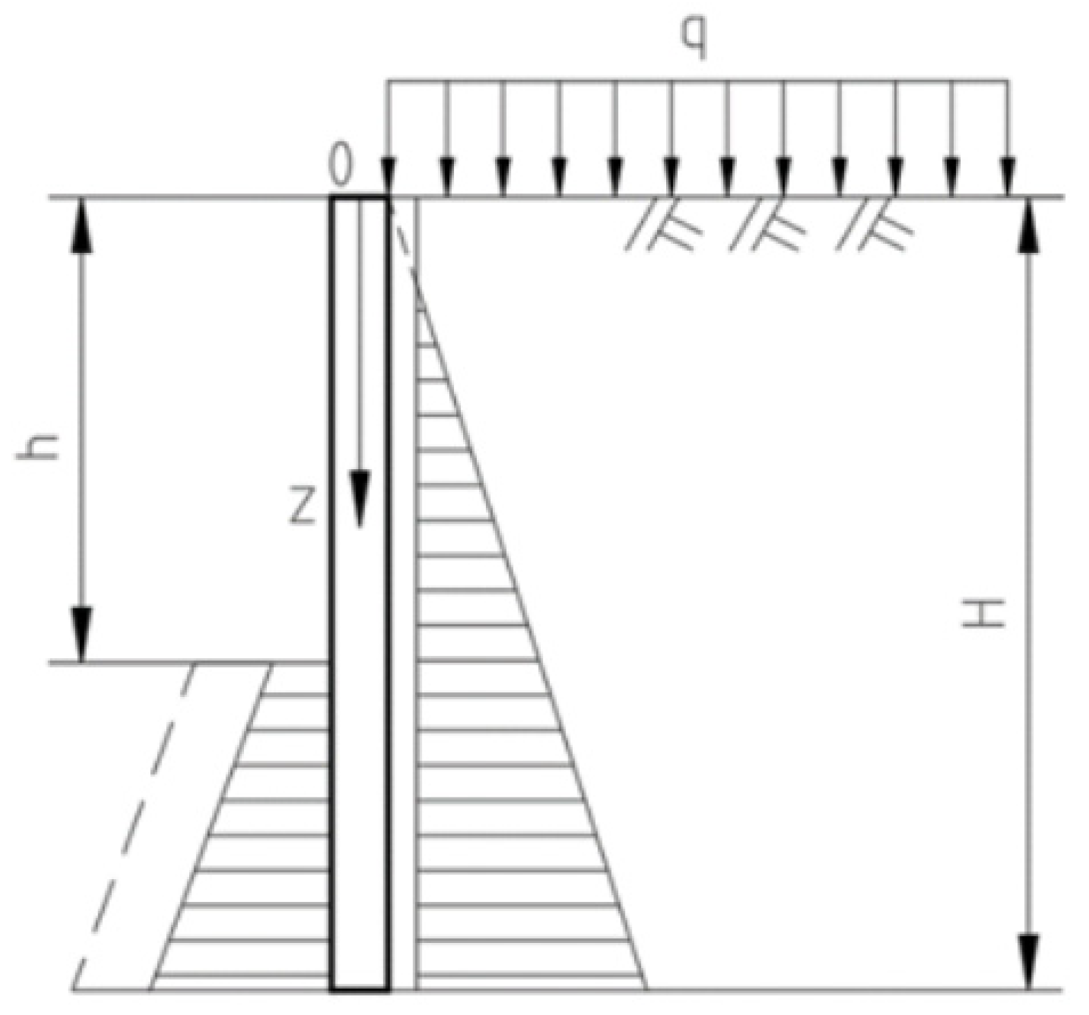
In the calculation model depicted in Figure 1, the zero point in the coordinate system is at the top of the wall, with the calculation direction moving downward in the z-direction. The wall height is designated as H , while the excavation depth for the pit is denoted as h . Considering more situations, there are n internal support members within the excavation depth, with the various distances of these members from the top of the wall referred to as h i .
(2)
It is assumed that the enclosure structure is made of a linear elastomer, and its displacement calculation is a plane strain problem. The unit width of the enclosure wall, whose bottom end is assumed to be fixed, is taken as the calculation and analysis object. The enclosure wall is subjected to active soil pressure and water pressure outside the pit, passive soil pressure and water pressure below the excavation surface, and internal support constraints above the excavation surface.
(3)
The soil water pressure is calculated using the Rankine theory, according to the principle that both soil pressure and water pressure are considered, respectively. The active soil pressures outside the pit acting on the enclosure wall are distributed in a triangular shape, whereas the passive soil pressures beneath the excavation surface are distributed in a trapezoidal or triangular shape, as illustrated in Figure 2. Likewise, the pore water pressures within and outside the pit acting on the enclosure wall are distributed in a triangular shape, as depicted in Figure 3.
(4)
The internal support member is also characterized as a linear elastomer at the pivot point between the retaining wall and the internal support member, conforming to the deformation coordination criterion. Specifically, this implies that the condition of equivalent displacement is fulfilled.

3. Calculation of the Horizontal Displacement of the Pit Enclosure Structure

Several factors need to be considered to calculate the horizontal displacement of the enclosure wall with n internal support members, as shown in Figure 1. These include the active soil pressure and the pore water pressure outside the pit, the passive soil pressure and the pore water pressure inside the pit, and the internal support member reaction force.

3.1. Calculation of Soil and Water Pressures Inside and Outside the Pit

The model of the enclosure wall acted on by soil and water pressures is depicted in Figure 2 and Figure 3. Based on the above calculation conditions, the soil pressure outside the pit can be determined as follows:
P a = ( γ 1 z + q ) K a 2 c 1 K a
K a = tan 2 45 ϕ 1 / 2 , where ϕ 1 is the weighted mean value of the soil internal friction angle on the active pressure side (unit: °); γ 1 is the weighted mean value of the soil weight on the active pressure side, with the natural weight taken above the water table and the floating weight taken below the water table (unit: k N m 3 ); c 1 is the mean value of the cohesive force in the soil on the active pressure side (unit: k P a ); and q is the overload on the foundation pit.
The soil pressure acting on the enclosure wall inside the pit is determined using Equation (2), where the Rankine passive soil pressure is multiplied by a discount factor, α :
P p = α [ γ 2 ( z h ) k p + 2 c 2 k p ]
K p = tan 2 45 + ϕ 2 / 2 . Here, ϕ 2 is the weighted average value of the soil internal friction angle on the passive pressure side (unit: °); γ 2 is the weighted mean value of the soil weight on the passive pressure side, taking into account the natural gravity above the water table and the floating weight below the water table (unit: k N m 3 ); and c 2 is the mean value of the cohesion of the soil on the passive pressure side (unit: k P a ).
Equation (3) is used to calculate the pore water pressure both inside and outside the pit:
P a w = γ w ( z a ) ;    P p w = γ w ( z b )
where P a w is the water pressure on the active side (unit: k P a ); P p w is the water pressure on the passive side (unit: k P a ); γ w is the groundwater gravity (unit: k N m 3 ); a is the distance from the groundwater level outside the pit to the Earth’s surface (unit: m ); and b is the distance from the groundwater level inside the pit to the excavation face of the foundation pit (unit: m ).

3.2. Internal Support Member Constraint Force Solution

According to the assumption above, the bottom of the enclosure wall is a fixed support. An enclosure wall is a statically indeterminate structure as long as there is only an internal support member above the excavation face of the foundation pit. The horizontal support member constraint force cannot be derived from the static equilibrium equation. For the analysis, the i th elastic support in Figure 1 is used as an example.
Considering that only the enclosure wall at z = h i is subjected to the internal support binding force, whose value is a unit of horizontal force, the bending moment produced by the horizontal force on the enclosure wall is calculated according to the following formula:
M i = z h i
The actual binding force on the enclosure wall at the i th elastic support is F i , and the bending moment of the enclosure wall when subjected to F i is
M F i = F i ( z h i )
According to the previous calculation assumptions in this paper and the unit load method, the horizontal displacement of the enclosure wall at z = h i under the action of F i can be calculated as follows:
Δ i F i = 1 E I h i H M F i M i d z = 1 E I h i H F i ( z h i ) 2 d z
Here, E is the elasticity modulus of the enclosure wall (unit: M P a ); I is the moment of inertia of the enclosure wall (unit: m 4 ); and E I is the flexural rigidity of the enclosure wall.
Similarly, except for F i , Equation (7) can be used to find the horizontal displacements of the enclosure wall at z = h i induced by other n 1 constraint forces F j :
Δ i F j = 1 E I h i H M F j M i d z = 1 E I h i H F j ( z h i ) ( z h j ) d z
The horizontal displacement of the enclosure wall at depth z = h i under the action of active soil pressure P a outside the pit is obtained via the following steps:
The shear force of the enclosure wall under the action of active soil pressure is
Q a z = 0 z P a d z = 0 z [ ( γ 1 z + q ) K a 2 c 1 K a ] d z = 1 2 γ 1 K a z 2 + ( q K a 2 c 1 K a ) z
The bending moment of the enclosure wall under the action of active soil pressure can be obtained using the following formula:
M a z = 0 z Q z a d z = 0 z [ 1 2 γ 1 K a z 2 + ( q K a 2 c 1 K a ) z ] d z = 1 6 γ 1 K a z 3 + 1 2 ( q K a 2 c 1 K a ) z 2
The horizontal displacement of the enclosure wall at depth z = h i is
Δ i p a = 1 E I h i H M a z M i d z = 1 E I h i H [ 1 6 γ 1 K a z 3 + 1 2 ( q K a 2 c 1 K a ) z 2 ] ( z h i ) d z
Similarly, the shear force of the enclosure wall under passive soil pressure P P in the pit is
Q p z = α [ K p 2 γ 2 ( z h ) 2 + 2 c 2 K p ( z h ) ]
The bending moment of the enclosure wall under the action of P p can be obtained by the following formula:
M p z = α [ K p 6 γ 2 ( z h ) 3 + c 2 K q ( z h ) 2 ]
The horizontal displacement of the enclosure wall at depth z = h i is given by P p :
Δ i P p = 1 E I h i H M p z M i d z = 1 E I h i H α [ K p 6 γ 2 ( z h ) 3 + c 2 K q ( z h ) 2 ] ( z h i ) d z
The displacements produced by the water pressure in the active and passive zones at depth z = h i are
Δ i P a w = 1 E I h i H M a z M i d z
Δ i P p w = 1 E I h i H M p w M i d z
where M a w and M p w are the bending moments generated by the water pressure on the enclosure wall in the active and passive zones, respectively.
The displacements of the enclosure wall are obtained at a depth of z = h i , which are generated by loads P a , P p , P a w , P p w , as well as n internal support member constraint forces.
Using the elastic superposition method, the total displacement of the enclosure wall at a specific depth z = h i can be calculated as follows:
Δ i = Δ i F i + j i n Δ i F j + Δ i P a + Δ i P p + Δ i a w + Δ i p w
By repeating the above steps, the displacements Δ j of the enclosure wall at the other j i pivot points can be determined. However, there are n unknowns F i and F j in the expressions of Δ i and Δ j . Thus, it is not yet possible to obtain Δ i or Δ j .
According to the calculation model and assumption conditions, the load acting on the i th internal support member from the enclosure wall is the reaction force F i . Considering the deformation coordination between the enclosure wall and the internal support member at the pivot point, the displacement of the internal support member at the point is also equal to Δ i . A linear elastic structural analysis is carried out for the internal support member, and the relationship between the loads and horizontal displacement can be expressed as follows:
F i = k i Δ i
The coefficient of elastic fulcrum stiffness, k i (unit: k N / m ), can be determined using sources available in the literature [14,27].
In summary, for an enclosure wall with n internal support members, Equations (16) and (17) can be linked to determine F i , F j and the corresponding Δ i and Δ j .
Remark 1. 
The soil layer parameters and the structural parameters of the enclosure wall determine the calculated results of horizontal displacement. The way in which these parameters are obtained will affect the use of the calculation method. In practical applications, c ,  ϕ , and  γ  can be determined through a geotechnical test;  E  can been obtained by referring to the manufacturer’s report or material test; and  H  and  I  are decided by the engineering designer.

3.3. Calculation of the Horizontal Displacement of the Enclosure Wall

Based on the obtained F i , F j , P a , P p , P a w , and p p w , the horizontal displacement Δ at any point z 0 of the enclosure wall can be calculated as follows:
Δ = z 0 H M M z E I d z
where M z represents the real bending moment of the enclosure wall, which can be obtained as per Equation (19); M denotes the bending moment of the enclosure wall when a unit force is applied at the specific point z 0 , which can be obtained according to Equation (20); and the remaining symbols hold the same meanings as described above.
M z = M F 1 + + M F i + M F n + M a z + M p z + M a w + M p w        = i = 1 n M F i + M a z + M p z + M a w + M p w
M = ( z z 0 ) × 1 = z z 0
It is worth noting that, when n equals zero in Equation (19), the enclosure wall transforms into a cantilever structure. At this stage, the i = 1 n M F i component is nonexistent, and the enclosure structure is subjected solely to the soil and water pressure inside and outside the excavation. The bending moment is then plugged into Equation (18), and the horizontal displacement of the enclosure structure can be obtained at any desired position.
Moreover, in addition to the retaining and protection structures of the enclosure wall (pile) with an internal support member, the horizontal displacement of a wall with an anchor-pulled support structure can also be obtained using the above method. In this case, the corresponding anchor force on the enclosure wall can be determined using Equations (16) and (17) if the elastic fulcrum stiffness coefficient of the anchor-pulled support structure can be provided. Subsequently, by employing Equation (18), the horizontal displacement can be determined at any desired position for the enclosure wall (pile) with an anchor-pulled support structure.

4. Case Analysis

To verify the validity of the research results, an underground station pit project and several engineering examples from the literature [16] were selected as the research objects. The horizontal displacement of the retaining wall was calculated and compared with the measured results on site. MATLAB R2020b software was used to compile the solving procedure for the horizontal displacement of the pit enclosure structure into calculation code, and the computer automatically completed the entire calculation process.

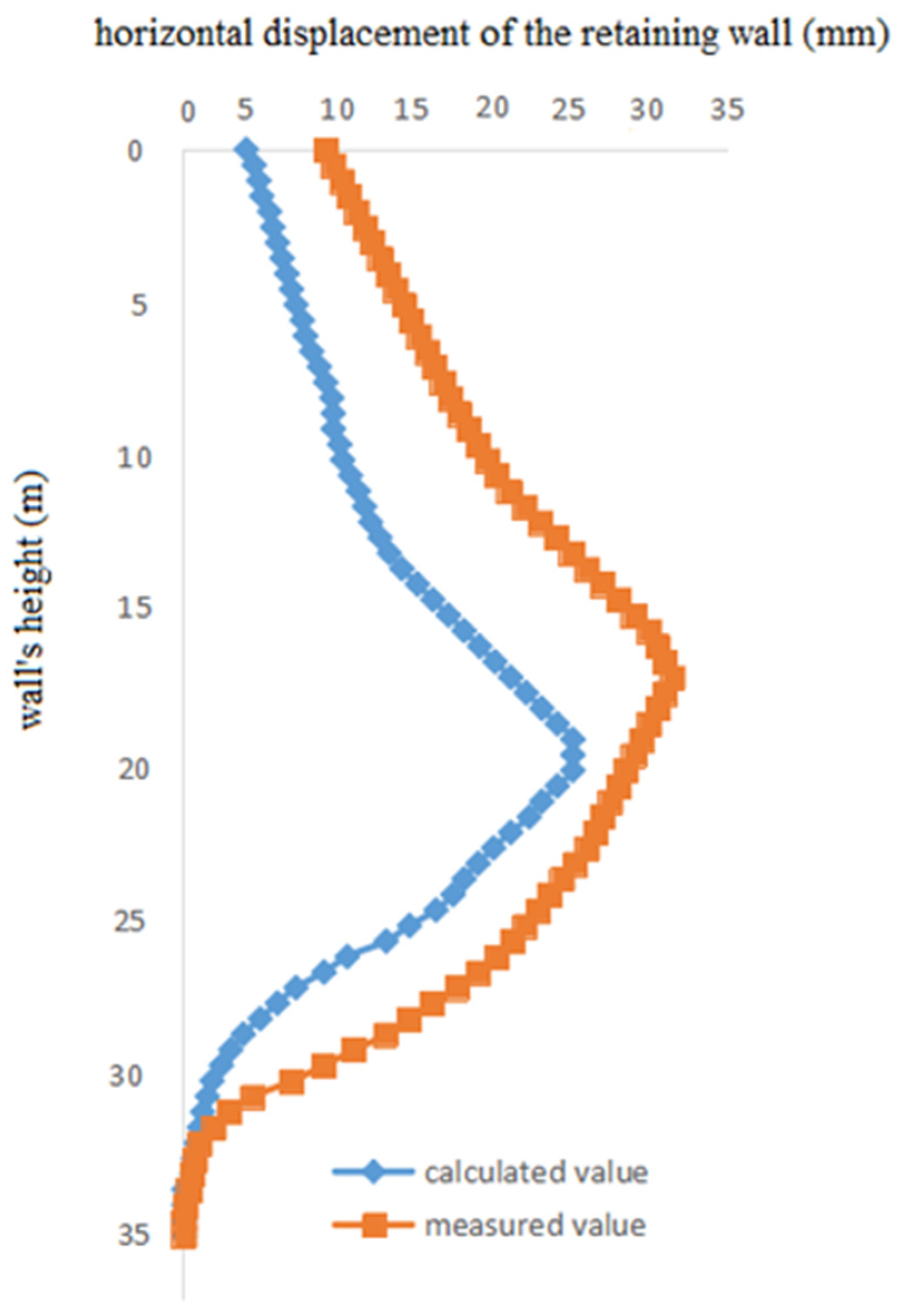
4.1. Horizontal Displacement of the Enclosure Wall for a Metro Station Foundation Pit

The excavation pit of a subway station was constructed using the open-cut method; the standard section excavation width was 19.3 m, and the excavation depth h was 17.8 m. The retaining wall was 1 m thick and extended 35 m deep. The top of the retaining wall was level with the ground surface. A concrete support member measuring 800 × 1000 mm located 1.6 m below the ground surface was strutted to the retaining wall. From the ground surface, steel supports with a diameter of 609 mm and a thickness of 16 mm were placed as the second to fourth inner support members at distances of h 2 = 7.6 m, h 3 = 11.2 m, and h 4 = 14.8 m. The E value of the enclosure wall was 21,000 MPa; the stiffness coefficient of the elastic fulcrum of the concrete support was k = 1.5 × 10⁵ kN/m, while the stiffness coefficient of the steel support was 4.5 × 10⁴ kN/m. The physico-mechanical indices of the foundation soil layer can be found in Table 1.
The structural parameters of the enclosure wall, along with the elastic support stiffness coefficient and soil layer parameters of the pit, were inputted into a MATLAB calculation code. After running the code, four internal support constraint forces were obtained, namely, F 1 = 640.8 kN , F 2 = 884.8 kN , F 3 = 910.6 kN , and F 4 = 1062.4 kN . The calculated values for the horizontal displacement of the enclosure wall were then compared to the field measurement results, as illustrated in Figure 4.
Overall, based on our calculations, the curve of the horizontal displacement of the enclosure wall closely matches the measured value curve in the field. The maximum horizontal displacements are both approximately 1 m from the bottom of the pit. The calculated maximum value is located on the lower side of the bottom of the foundation pit. In contrast, the measured maximum value in the field is located on the upper side of the bottom of the foundation pit. The calculated minimum value and measured minimum value for the horizontal displacement are located at the bottom of the retaining structure, and their values are nearly 0. Our assumption of fixed support at the end of the retaining wall is close to the actual engineering situation, and the horizontal displacement calculation formula provided in this paper is applicable.
Remark 2. 
The standard section here is not defined in any standard code provision. To meet different spatial functional requirements, the subway station is designed with multiple excavation sections, and the section with the longest excavation length is called the standard section.

4.2. Comparison of Calculation Examples for Horizontal Displacement at the Top of the Wall

Based on the literature [6], ten examples of cement–soil gravity retaining structures in the Shanghai area were obtained, all of which were constructed on the typical soft soil layers of Shanghai, and their horizontal displacements at the top of the wall were calculated.
The outcomes presented in Table 2 show that the horizontal displacements at the top of the wall, obtained by applying the method introduced in this study, are consistently smaller than the measured values. The maximum deviation rate is 9.2%, while the minimum is 4.4%. Nevertheless, the deviation between the calculated and measured values falls within the acceptable range of 10%, indicating that the proposed method is reliable and applicable. Conversely, the horizontal displacements at the top of the wall calculated in the literature [16] deviate significantly from the measured values, with a maximum deviation of 28.2% and a minimum deviation of 1.4%.
To gauge the efficacy of the method presented in this paper, which can also be used to calculate the horizontal displacement of cantilever retaining structures, five cases of these enclosure structures were chosen for calculation purposes. Then, their wall top horizontal displacements were computed and compared with the project’s measured values and calculated values in the literature [16]. The results are shown in Table 2.
The discrepancy between the calculated and measured values can be attributed to the fact that the retaining structure is assumed to be a linear elastic body, and the calculated displacement value is generated only by elastic deformation. In contrast, the measured values are based on the actual working conditions of the project site. This leads to certain differences between the calculation assumptions in this study and the actual working conditions of the project.
The deviation between the calculation results in this study and those in the literature [6] stems from the different theoretical underpinnings of the two methods. The method proposed in this paper adheres strictly to the structural mechanics of the elastic displacement calculation. At the same time, Ref. [16] utilizes mathematical and statistical methods to normalize the wall displacement function. Then, the horizontal displacement values at the top of the wall are obtained via the function, and their results are sometimes larger or smaller than the measured values. The degree of deviation between the calculated and measured values in [16] is larger than that of the method in this paper, which is related to the different theories on which the two methods are based.
In fact, the horizontal displacement of the retaining structure of a foundation pit is not only related to the excavation depth h and the wall height H but also to load parameters, such as q ; soil layer parameters, such as c i , ϕ i , and γ i ; and the structural parameters of the enclosure wall, such as E and I . If there are internal support members that act on the retaining wall, then the horizontal displacement is also related to the elastic support stiffness coefficient k i . The calculation method presented in this article comprehensively reflects the influence of these factors.
In Table 2, it can be seen that there are significant differences in the horizontal displacements of the retaining structures in the various foundation pits, regardless of whether these values are the calculated values in this article, literature calculations, or measurement values. In particular, this situation exists such that the excavation depth h and the wall height H are larger but the horizontal displacements of the retaining walls are smaller between the different foundation pits, which is closely related to the differences in the above parameters.

5. Conclusions

In this study, a solution formula for the redundant constraint force of a retaining wall is derived, and a novel method for computing the horizontal displacement of a retaining structure in a deep foundation pit is proposed. The proposed method assumes that the enclosing wall and internal support members are linear elastic bodies, and the coordination conditions of deformation between them are considered. The method is straightforward and can be easily implemented using the MATLAB programming language.
Notably, the horizontal displacement calculation method applies not only to the structure of a diaphragm wall with an internal support member but also to the horizontal displacement calculation of cantilevered and anchor-pulled retaining structures. The method can be conveniently used if the corresponding parameters of the enclosure structure and the loading conditions are given.
A case study was conducted on a standard section with an excavation width of 19.3 m and an excavation depth h of 17.8 m. The structural parameters of the enclosure wall, along with the elastic support stiffness coefficient and soil layer parameters of the pit, were inputted into a MATLAB calculation code. Then, four internal support constraint forces F i and the calculated values of the horizontal displacement of the enclosure wall were obtained after running the code. The calculated curve closely matched the curve of values measured in the field. The horizontal displacements of the top of the wall of several cement–soil gravity enclosure structures mentioned in the literature were also calculated. The results of these calculations were then compared with the measured data and corresponding data from the literature. The examples provided clear evidence demonstrating that the proposed method is highly reliable for calculating the horizontal displacement of deep foundation pit enclosure structures.
Overall, the proposed method provides a clear and concise mechanical approach for calculating the horizontal displacement of deep foundation pit enclosure structures. Its ease of implementation and ability to accurately predict horizontal displacement make it a valuable tool for engineers and researchers.
Local and dynamic effects were not considered in the research model method. We will make this one of the future research focuses and directions in this field.

Author Contributions

Methodology, J.Z.; Software, F.Q. and J.C.; Investigation, J.C.; Writing—original draft, J.Z. All authors have read and agreed to the published version of the manuscript.

Funding

This research received no external funding.

Data Availability Statement

The original contributions presented in the study are included in the article, further inquiries can be directed to the corresponding author.

Conflicts of Interest

The authors declare no conflict of interest.

References

  1. Cao, C.-M.; Shi, Y.-L.; Long, Z.; Ye, S.-H. Stress and deformation analysis of deep foundation pit supported by pile and internal bracing under unsymmetrical loaded. Sci. Technol. Eng. 2023, 23, 2952–2959. [Google Scholar]
  2. Huang, Y.J.; Yuan, S.; Wang, C.; Zhang, Y.L. Theoretical analysis of displacement and axial force in support structures during dynamic adjustment of internal support systems in foundation pits. Tunn. Constr. 2023, 43, 761–769. [Google Scholar]
  3. Li, Y.; Ma, Z.; Gao, F.; Gong, P.; Gong, Z.; Li, K. of a deep foundation pit with hard surrounding rocks under different in-time transverse supporting conditions. Appl. Sci. 2024, 14, 2914. [Google Scholar] [CrossRef]
  4. Li, D.; Chen, Y.; Dai, B.; Wang, Z.; Liang, H.N. Numerical study of dig sequence effects during large-scale Excavation. Appl. Sci. 2023, 13, 11342. [Google Scholar] [CrossRef]
  5. Sun, Z.H.; Xu, C.J.; Fang, L.M.; Fan, R.D. Parameter analysis and discussion on design optimization of support structure of internal bracing foundation excavation under asymmetric loads. Chin. J. Appl. Mech. 2024, 41, 158–168. [Google Scholar]
  6. Zheng, G.; Zhu, H.H.; Liu, X.R.; Yang, G.H. Control of safety of deep excavations and underground engineering and its impact on surrounding environment. China Civ. Eng. J. 2016, 49, 1–24. [Google Scholar]
  7. Wang, W.D.; Wu, J.B.; Huang, S.M. Recent progress and characteristics of pit foundation in shanghai. Chin. J. Undergr. Space Eng. 2005, 1, 547–553. [Google Scholar] [CrossRef]
  8. Li, D.P.; Yan, C.H.; Zhang, S. Advances in researching influences of deep excavation on surrounding environment. Eng. J. Wuhan Univ. 2018, 51, 659–668. [Google Scholar]
  9. Li, D.; Liao, F.; Wang, L.; Lin, J.; Wang, J. Multi-stage and multi-parameter influence analysis of deep foundation pit excavation on surrounding environment. Buildings 2024, 14, 297. [Google Scholar] [CrossRef]
  10. Yang, B.; Zhang, C.; Su, N.; Xiao, Z. Influence of small radius curved shield tunneling excavation on displacement of surrounding soil. Buildings 2023, 13, 803. [Google Scholar] [CrossRef]
  11. Du, E.; Zhou, L.; Fei, R. Investigation on the stress and deformation evolution laws of shield tunnelling through a mining tunnel structure. Appl. Sci. 2023, 13, 8489. [Google Scholar] [CrossRef]
  12. Wang, R.; Yang, H.; Ni, P.; Zhao, C.; Guo, C.; Ma, H.; Dong, P.; Liang, H.; Tang, M. Model test and numerical simulation of a new prefabricated double-row piles retaining system in silty clay ground. Underg. Space 2023, 13, 262–280. [Google Scholar] [CrossRef]
  13. Yu, O.; Yunfei, G.A.; Kaikai, R. Deformation analytical solution for a retaining structure with an elastic support ring beam of a circular deep foundation pit. J. Shanghai Univ. (Nat. Sci. Ed.) 2024, 30, 128–139. [Google Scholar]
  14. JGJ120-2012; Technical Specification for Retaining and Protection of Building Foundation Excavations. National Standards of the People’s Republic of China: Beijing, China, 2012.
  15. Xu, H.Y.; Chen, L.Z.; Liu, Q.L. A simplified algorithm of lateral displacements of pile-anchor retaining structures. Rock Soil Mech. 2013, 34, 2323–2328. [Google Scholar]
  16. Wang, W.D.; Wang, H.R.; Huang, M.S.; Xu, Z.H. Simplified calculation method of lateral deformation of gravity retaining wall. J. Tongji Univ. (Nat. Sci.) 2011, 39, 814–818. [Google Scholar]
  17. Clough, G.W.; O’rourke, T.D. Construction induced movements of in situ walls proc.; design and performance of earth retaining structure. Geotech. Spec. Publ. 1990, 25, 439–470. [Google Scholar]
  18. Liu, X.W.; Shi, Z.Y.; Yi, D.Q.; Wu, S.M. Moment and Deformation Analysis of Retaining Structure of Foundation Pit in Whole Process of Construction. J. Build. Struct. 1998, 19, 58–64. [Google Scholar]
  19. Yan, M.; Feng, Y.Q.; Wang, R.X. Analysis of Flexible Retaining Structure of Deep Excavation and Its Comparison with Observed Results. J. Build. Struct. 1999, 20, 68–78. [Google Scholar]
  20. Huang, B.; Li, M.G.; Ma, Y.; Chen, J.J.; Wang, J.H. Elastic Foundation Beam Method Considering Coupling between Deformation Behavior of Retaining Wall and Earth Pressure. Chin. J. Undergr. Space Eng. 2019, 35, 802–810. [Google Scholar]
  21. Xiao, H.B.; Cai, W.M. A Calculating Method of Multi-braced Retaining structures based on excavation process having taken into account. Harb. Eng. 1992, 5, 25–37. [Google Scholar]
  22. Li, T.; Jiang, Y.H.; Zhu, L.H.; Guan, C.L. A novel method supporting for calculating stress and deformation of pile considering pile-soil interaction. J. Southwest Jiaotong Univ. 2016, 51, 14–21. [Google Scholar]
  23. Zhu, Y.P.; Wu, L.P.; Shi, D.B.; Zhao, Z.F.; Duan, X.G. Application of nonlinear soil resistance-pile lateral displacement curve based on Pasternak foundation model in foundation pit retaining piles. Rock Soil Mech. 2022, 43, 2581–2591. [Google Scholar]
  24. Kai, S.W.; Bengt, B.B. Lateral wall deflections of braced excavations in clay. J. Geotech. Eng. 1989, 115, 853–870. [Google Scholar]
  25. Youssef, M.A.; Andrew, J.W. Ground movement prediction for deep Excavations in soft clay. J. Geotech. Eng. 1996, 122, 474–486. [Google Scholar]
  26. Kung, G.T.; Juang, C.H.; Hsiao, E.C.; Hashash, Y.M. Simplified model for wall deflection and ground-surface settlement caused by braced excavation in clays. J. Geotech. Geoenviron. Eng. 2007, 133, 731–747. [Google Scholar] [CrossRef]
  27. Jin, Y.B.; Liu, D. Analytical solution calculation method research of pivot horizontal stiffness coefficient of inner support structure in deep foundation pit. Chin. J. Geotech. Eng. 2019, 41, 1031–1039. [Google Scholar]
  28. Hu, M.D.; Xia, M.Y. Cement-soil deep mixing pile as retaining wall displacement mechanism research. Undergr. Eng. Tunneling 1999, 1, 9–14. [Google Scholar]
  29. Liu, J.H.; Hou, X.Y. Manual of Excavation on Engineering; China Architecture & Building Press: Beijing, China, 1997. [Google Scholar]
  30. Li, X.F.; Wei, J.H.; He, Z.M. Integrated application of composite soil nailing, soil cement wall and anchor for retaining technology. Build. Constr. 2001, 23, 385–386. [Google Scholar]
  31. Ding, T.; Xu, J.M.; Li, W.H. Analysis on horizontal displacements of composite retaining structure for wide excavating. Build. Sci. 2005, 21, 76–79. [Google Scholar]
Figure 1. Retaining structure with inner support.
Buildings 14 01694 g001
Figure 2. Model for calculating the soil pressure on both sides of a retaining wall.
Buildings 14 01694 g002
Figure 3. Calculation model of the water pressure on both sides of a retaining wall.
Buildings 14 01694 g003
Figure 4. Comparison of the calculated and measured values for the horizontal displacement of the retaining wall.
Buildings 14 01694 g004
Table 1. Physico-mechanical indications of soils.
NO.Soil Layer NameLayer Depth/mGravitational Density/(kN·m−3)Internal Friction Angle/(°)Cohesive Force/(kPa)
Miscellaneous fill1.816.8120.8
Muddy clay4.917.71012
Fine sand2.419.031-
Silty clay9.418.32024
Fine sand218.930-
Gravelly clay14.518.52622
Table 2. Comparison between the calculated and measured horizontal displacements at the top of the wall.
NO.Project NameExcavation Depth/mWall Depth/mHorizontal Displacement of Top of Wall/mmDeviation
between
Calculated and Measured Values in Reference [6]/%
Deviation
between Text
Calculated and Measured
Values/%
Literature [6] Calculated ValuesMeasured ValueText Calculated Value
1Exhibition Centre West Second Hall [28]5.0010.037.352.048.228.27.3
2Hongji Building [28]5.9512.045.650.046.88.86.4
3Sun Plaza [29]6.715.0131.5180.0163.426.99.2
4West Gate Plaza [30]5.411.457.055.052.63.64.4
5A Water Supply Company Project [31]6.315.322.322.020.71.45.9
Disclaimer/Publisher’s Note: The statements, opinions and data contained in all publications are solely those of the individual author(s) and contributor(s) and not of MDPI and/or the editor(s). MDPI and/or the editor(s) disclaim responsibility for any injury to people or property resulting from any ideas, methods, instructions or products referred to in the content.

